

Page 1
Disposal / WEE declaration
Rechargeable Batteries and Batteries
The supplied rechargeable batteries or batteries are recyclable. Please
dispose of them at special waste collection points or your local dealer.
Only dispose of exhausted batteries or rechargeable batteries to ensure
environmental protection.
WEEE-Declaration
Your product is designed and manufactured with materials and
components of high quality, which are recyclable and can be reused.
The symbol means that your product should be disposed of separately
from household waste when it reaches its end of life. Please dispose of
this equipment at your local collection point or recycling center. Please
help to protect the environment in which we all live.
CE
All specifications and appearances are subject to change without
notice. All information was correct at time of printing. Musikhaus Kirstein
GmbH does not guarantee for the accuracy or completeness of any
description, photograph or statement contained in this manual. Printed
colors and specifications may vary slightly from product. Products from
Musikhaus Kirstein GmbH are only sold through authorized dealer.
Distributors and dealers are not agents of Musikhaus Kirstein GmbH
and have no authority to bind Musikhaus Kirstein GmbH legally in any
way. This manual is protected by copyright. Any copying or reprint, even
in excerpts, is only allowed with written consent of Musikhaus Kirstein
GmbH. The same applies to reproduction or copying of images, even in
altered form.
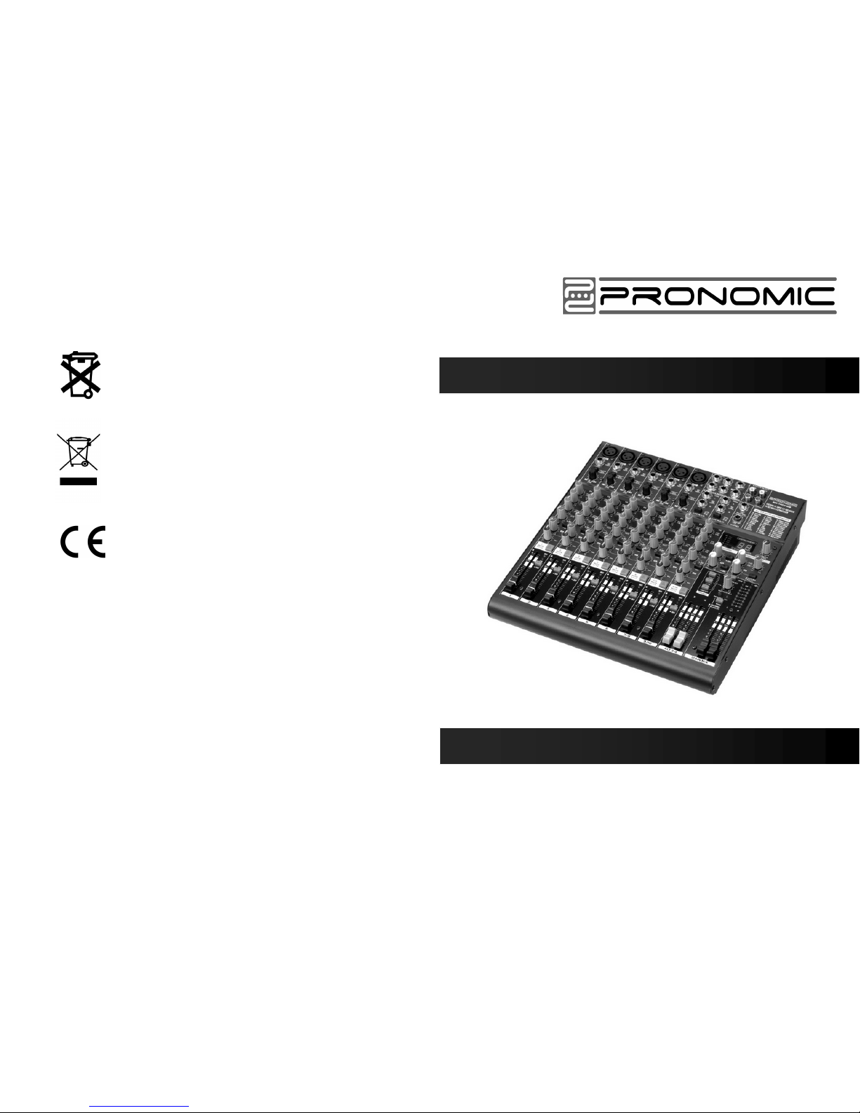
Pronomic MX-1404FX
Users manual
00024065
Version 01/2012
Page 2
The symbol is used to indicate that some hazardous live terminals are involved within this apparatus, even
under the normal operating conditions, which may be sufficient to constitute the risk of electric shock or
death.
The symbol is used in the service documentation to indicate that specific component shall be replaced
only by the component specified in that documentation for safety reasons.
Protective grounding terminal
Alternating current/voltage
Hazardous live terminal
ON: Denotes the apparatus is turned on
OFF: Denotes the apparatus is turned off.
WARNING: Describes precautions that should be observed to prevent the danger of injury or death to the operator.
CAUTION: Describes precautions that should be observed to prevent danger of the apparatus.
IMPORTANT SAFETY INSTRUCTIONS
·Read these instructions.
·Keep these instructions.
·Heed all warning.
·Follow all instructions.
Water & Moisture·
The apparatus should be protected from moisture and
rain, can not used near water, for example: near bathtub, kitchen sink or a swimming pool, etc.
·Heat
The apparatus should be located away from the heat
source such as radiators, stoves or other appliances
that produce heat.
·Ventilation
Do not block areas of ventilation opening. Failure to
do could result in fire. Always install accordance with
the manufacturer's instructions.
·Object and Liquid Entry
Objects do not fall into and liquids are not spilled into
the inside of the apparatus for safety.
·Power Cord and Plug
Protect the power cord from being walked on or pinched
particularly at plugs, convenience receptacles, and the
point where they exit from the apparatus.
Do not defeat the safe ty purpose of the pola rized or
grounding-type plug. A polarized plug has two blades
with one wider than the other. A grounding type plug
has two blades and a third grounding prong. The wide
blade or the third prong is provided for your safety.
If the provided plug does not fit into your outlet, refer to
electrician for replacement.
CAU TION
RISK OF E LECTR IC SHOC K
DO NOT OP EN
IMPORTANT SAFETY SYMBOLS
·Power Supply
The apparatus should be connecte d to the power supply
only of the type as marked on the apparatus or described
in the manual. Failure to do could result in damage to the
product and possibly the user.
Unplug this ap paratus durin g lightning s torms o r when
unused for long periods of time.
·Fuse
To prevent the risk of fire and d amaging the unit, please
use only of th e recommende d fuse type a s described i n
the manual. Before replacing the fuse, make sure the unit
turned off and disconnected from the AC outlet.
·Electrical Connection
Improper electrical wiring may invalidate the product warranty.
·Cleaning
Clean only with a dry cloth. Do not use any solvents such
as benzol or alcohol.
·Servicing
Do not implement an y servicing other t han those means
describe d in the man ual. Refe r all serv icing to q ualified
service personnel only.
·Only use accessories/attachments or parts recommended
by the manufacturer.
·Warning
Please remember the high sound pressure do not only
temporarily damage your sense of hearing, but can also
cause permanent damage. Be careful to select a suitable
volume.
Mono inputs
Microphone inputs (XENYX Mic Preamp)
Type XLR, electronically balanced,
discrete input circuit
Mic E.I.N. (20 Hz - 20 kHz)
@ 0 Ω source resistance
@ 50 Ω source resistance
@ 150 Ω source resistance
-134 dB / 135.7 dB A-weighted
-131 dB / 133.3 dB A-weighted
-129 dB / 130.5 dB A-weighted
Frequency response
<10 Hz -150 kHz (-1 dB),
<10 Hz -200 kHz (-3 dB)
Gain range
+10 to +60 dB
Max. Input level
+12 dBu @ +10 dB gain
Impedance
approx. 2.6 k balancedΩ
110 dB / 112 dB A-weighted
Signal-to noise ratio
(0 dBu In @ +22 dB gain)
Distortion (THD+ N) 0.005% / 0.004% A-weighted
Line input
Type
Impedance
Gain range
Max. Input level
1
Fade-out attenuation
(Crosstalk attenuation)
Main fader closed
Channel muted
Channel fader closed
Frequency response
Microphone input to main out
<10 Hz - 90 kHz
<10 Hz - 160 kHz
+0 dB / -1 dB
+0 dB / -3 dB
Stereo inputs
Type
1/4" TRS connector,
Impedance
Max. Input level
electronically balanced
approx. 20 k Ω
+22 dBu
EQ mono channels
EQ stereo channels
9
5.SPECIFICATIO NS
1/4" TRS connector,
electronically balanced
approx. 20 banlanced Ω
10 k unbanlanced Ω
-10 to +40 dB
30 dBu
90 dB
89.5 dB
89 dB
Low
Mid
High
Low
Mid
High
80 Hz / 15 dB
2.5 kHz / 15 dB
12 kHz / 15 dB
80 Hz / 15 dB
2.5 kHz / 15 dB
12 kHz / 15 dB
Aux sends
Stereo aux return
Type
Impedance
Max.output level
1/4"T S connector, unbalanced
approx. 20 k Ω
+22 dBu
Main outputs
Type
Impedance
Max.output level
XLR electronically balanced
approx. 240 bal./ 120 unbal. Ω Ω
+28 dBu
Control room outputs
Type
Impedance
Max.output level
1/4"TS connector, unbal.
approx. 120 Ω
+22 dBu
Headphones output
Type
Max.output level
1/4"TRS connector, unbalanced
+19 dBu / 150 (+25 dBu)Ω
DSP
Converter
24-bit Texas Instruments
24-bit Sigma-Delta.
64/128-times oversampling
40 kHz
Sampling rate
2
Main mix system data
Noise
Main mix @ -∞,
Channel fader -∞
Main mix @ 0 dB,
Channel fader -∞
Main mix @ 0 dB,
Channel fader @ 0 dB
-105 dB / -108 dB A-weighted
-95 dB / -97 dB A-weighted
-82.5 dB / -85 dB A-weighted
Power supply
Mains voltage
Power consumption
Fuse
100 -240 V~, 50/60 Hz
40 W
Mains connection
Standard IEC receptacle
100 -240 V~, T 1.6 A H 250V
Physical
1204FX
Dimensions (H x W x D) 245 x 324 x 86 mm
2.1kg
weight (net)
1404FX
Dimensions (H x W x D)
298 x 324 x 86 mm
2.3kgweight (net)
1604FX
1804FX
Mea surin g condi tions :
1: 1kHz rel.to 0 dBu; 20 Hz - 20 kHz, line input; main output; unity gain.
2: 20Hz - 20kHz; measured at main output. Channels 1 - 4 unity gain: EQ flat; all
channels on main mix; channels 1/3 as far left as possible, channels 2/4 as far
right as possible. Reference = +6 dBu.
LongerdB is constantly striving to manintain the highest professional standards. As a
result of these efforts, modifications may be made from time to existing products without
prior notice. Specifications and appearance may differ from those listed or illustrated.
1/4" TRS connector,
Type
electronically balanced
approx. 20 k bal. /10 k unbal. Ω Ω
+22 dBu
Impedance
Max.input level
Dimensions (H x W x D)
351 x 324 x 86 mm
2.5kgweight (net)
Dimensions (H x W x D)
404 x 324 x 86 mm
2.7kgweight (net)
MX S e r ies M i xer
Page 3
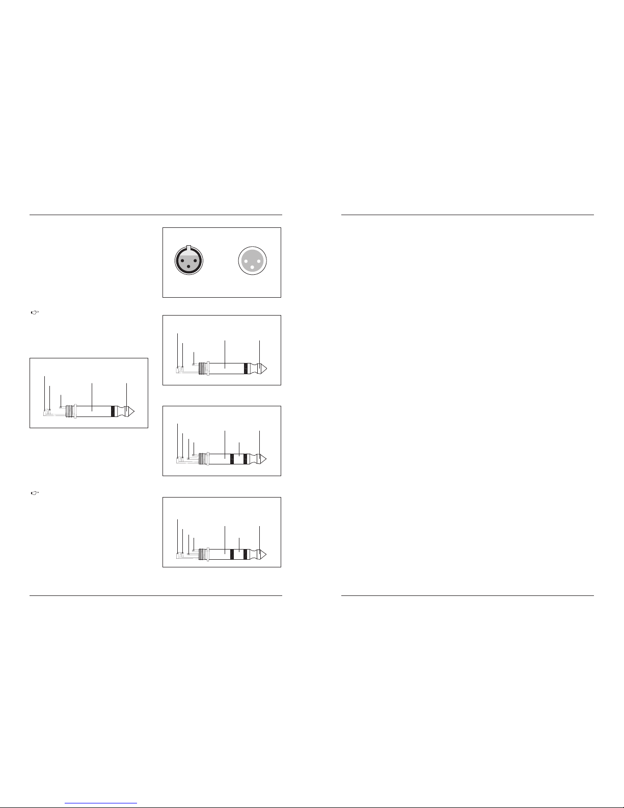
TABLE OF CONTENTS
1.INTRODUCTION................................................. .. .. .. .. .. .. .. .. .. .. .. .. .. .. .. .. .. .. ..4
1.1 G enera l mixin g conso le func tions ..... ..... ..... ..... ...... ..... ..... ..... ..... ..... ..... ..... ..... ..... ..... ..... ..... ..... ..... ..... ..... ..... ..4
1.2 Th e user’s man ual.. ..... ..... ..... ...... ..... ..... ..... ..... ..... ..... ..... ..... ..... ..... ..... ..... ..... ..... ..... ..... ..... ..... ..... ..... ..... ..... .4
1.3 B efore y ou get st arted ..... ..... ..... ...... ..... ..... ..... ..... ..... ..... ..... ..... ..... ..... ..... ..... ..... ..... ..... ..... ..... ..... ..... ..... ..... ...4
1.3 .1 Ship ment ..... ..... ..... ..... ..... ..... ..... ..... ..... ..... ..... ..... ..... ..... ..... ...... ..... ..... ..... ..... ..... ..... ..... ..... ..... ..... ..... ... 4
1.3 .2 Init ial ope ratio n.... ..... ..... ..... ...... ..... ..... ..... ..... ..... ..... ..... ..... ..... ..... ..... ..... ..... ..... ..... ..... ..... ..... ..... ..... ..... 4
1.3 .3 Onli ne regi strat ion.. ..... ..... ..... ...... ..... ..... ..... ..... ..... ..... ..... ..... ..... ..... ..... ..... ..... ..... ..... ..... ..... ..... ..... ..... ... 4
2.CONTROL ELE ME NT S AND CONNECTOR S ... .. .. .. .. .. .. .. .. .. .. .. .. .. .. .. .. .. .. .. .. .. 4
2.1 M ono cha nnels ..... ..... ..... ..... ...... ..... ..... ..... ..... ..... ..... ..... ..... ..... ..... ..... ..... ..... ..... ..... ..... ..... ..... ..... ..... ..... ..... ...5
2.1 .1 Micr ophon e and lin e input ..... ..... ..... ..... ...... ..... ..... ..... ..... ..... ..... ..... ..... ..... ..... ..... ..... ..... ..... ..... ..... ..... .....5
2.1 .2 Equa lizer. ..... ..... ..... ..... ...... ..... ..... ..... ..... ..... ..... ..... ..... ..... ..... ..... ..... ..... ..... ..... ..... ..... ..... ..... ..... ..... ..... ..5
2.1 .3 Aux sen ds... ..... ..... ..... ...... ..... ..... ..... ..... ..... ..... ..... ..... ..... ..... ..... ..... ..... ..... ..... ..... ..... ..... ..... ..... ..... ..... .... 5
2.1 .4 Rout ing swi tch, so le and ch annel f ader.. ..... ..... ..... ..... ...... ..... ..... ..... ..... ..... ..... ..... ..... ..... ..... ..... ..... ..... .... 6
2.2 S tereo c hanne ls... ..... ..... ..... ...... ..... ..... ..... ..... ..... ..... ..... ..... ..... ..... ..... ..... ..... ..... ..... ..... ..... ..... ..... ..... ..... ..... ... 6
2.2 .1 Chan nel inp uts.. ..... ..... ..... ..... ...... ..... ..... ..... ..... ..... ..... ..... ..... ..... ..... ..... ..... ..... ..... ..... ..... ..... ..... ..... ..... ... 6
2.2 .2 Equa lizer s tereo c hanne ls... ..... ..... ..... ...... ..... ..... ..... ..... ..... ..... ..... ..... ..... ..... ..... ..... ..... ..... ..... ..... ..... ..... .6
2.2 .3 Aux sen ds ster eo chan nels. ..... ..... ..... ..... ...... ..... ..... ..... ..... ..... ..... ..... ..... ..... ..... ..... ..... ..... ..... ..... ..... ..... ..6
2.2 .4 Rou ting sw itch, s ole and c hanne l fader. ..... ..... ..... ..... ...... ..... ..... ..... ..... ..... ..... ..... ..... ..... ..... ..... ..... ..... ..... 6
2.3 C onnec tor pan el and ma in sect ion ... ..... ..... ..... ...... ..... ..... ..... ..... ..... ..... ..... ..... ..... ..... ..... ..... ..... ..... ..... ..... ..... ...6
2.3 .1 Aux sen ds 1 and 2 ... ..... ..... ..... ...... ..... ..... ..... ..... ..... ..... ..... ..... ..... ..... ..... ..... ..... ..... ..... ..... ..... ..... ..... ..... ...6
2.3 .2 Aux sen d conne ctors 1 a nd 2... ..... ..... ..... ...... ..... ..... ..... ..... ..... ..... ..... ..... ..... ..... ..... ..... ..... ..... ..... ..... ..... ...7
2.3 .3 Ster eo aux re turn co nnect ors.. ..... ..... ..... ...... ..... ..... ..... ..... ..... ..... ..... ..... ..... ..... ..... ..... ..... ..... ..... ..... ..... ...7
2.3 .4 Ster eo aux re turn. ..... ..... ..... ...... ..... ..... ..... ..... ..... ..... ..... ..... ..... ..... ..... ..... ..... ..... ..... ..... ..... ..... ..... ..... ..... .7
2.3 .5 Tape inpu t / tape ou tput. ..... ..... ..... ..... ..... ..... ..... ..... ..... ..... ..... ..... ..... ..... ..... ..... ..... ..... ..... ..... ..... ..... ..... ...7
2.3 .6 Leve l metre a nd moni torin g.... ..... ..... ..... ...... ..... ..... ..... ..... ..... ..... ..... ..... ..... ..... ..... ..... ..... ..... ..... ..... ..... ... 8
2.3 .7 Alt 3-4 a nd main m ix fade r..... ..... ..... ..... ...... ..... ..... ..... ..... ..... ..... ..... ..... ..... ..... ..... ..... ..... ..... ..... ..... ..... .....8
2.4 R ear vie w of 1204 FX/12 04... ..... ..... ..... ...... ..... ..... ..... ..... ..... ..... ..... ..... ..... ..... ..... ..... ..... ..... ..... ..... ..... ..... ..... ....9
2.4 .1 Main m ix outp uts, Alt 3 -4 outp uts and r oom out puts. ..... ..... ..... ...... ..... ..... ..... ..... ..... ..... ..... ..... ..... ..... ..... ...9
2.4 .2 Volta ge supp ly, phant om powe r and fus e.... ..... ..... ..... ..... ..... ..... ..... ..... ..... ..... ..... ..... ..... ..... ..... ..... ..... ... . 9
3.DIGITAL EF FE CT S PR OC ES SO R. .. .. .. .. .. .. .. .. .. .. .. .. .. .. .. .. .. .. .. .. .. .. .. .. .. .. .. .. .. . 9
4.INSTAL LTI ON .. .. .. .. .. .. .. .. .. .. .. .. .. .. .. .. .. .. .. .. .. .. .. .. .. .. .. .. .. .. .. .. .. .. .. .. .. .. .. .. .. .. .. .. .10
4.1 R ack mou nting ..... ..... ..... ..... ...... ..... ..... ..... ..... ..... ..... ..... ..... ..... ..... ..... ..... ..... ..... ..... ..... ..... ..... ..... ..... ..... ..... .10
4.2 .1 Audio c onnec tions ..... ..... ..... ..... ...... ..... ..... ..... ..... ..... ..... ..... ..... ..... ..... ..... ..... ..... ..... ..... ..... ..... ..... ..... .. 10
4.2 C able co nnect ions. ..... ..... ..... ..... ...... ..... ..... ..... ..... ..... ..... ..... ..... ..... ..... ..... ..... ..... ..... ..... ..... ..... ..... ..... ..... ..... 10
5.SPECIFICATIO NS .. .. .. .. .. .. .. .. .. .. .. .. .. .. .. .. .. .. .. .. .. .. .. .. .. .. .. .. .. .. .. .. .. .. .. .. .. .. .. .. .. 11
MX S e r ies M i xer
18
MX S e r ies M i xer
4.1 R ack mou nting
Before you can attach the rack mount wings to the mixing
console, you need to remove the screws holding the left and
right side panels. Use these screws to fasten the two wings
onto the console, being careful to note that each wing fits a
specific side. With the rack mount wing installed. You can mount
the mixing console in a commercially available 19"rack. Be sure
to allow for proper air flow around the unit, and do not place the
mixing console close to radiators or power amps. So as to avoid
overheating.
You will need a larger number of ca ble for the various
connecti ons to and fro m the console. The ill ustrations below
show. The wing of these cables . Be sure to use only high-g rade
cable.
Please use commercia l RCA cables to wire the 2-track inpu ts
and outputs.
You can, of course, also connect un balanced devices to the
balanced in put/outputs. Use eit her mono plugs, or ensure that
ring and sleeve ar e bridged inside the stereo pl ug (or pins 1 & 3
in the case of XLR connec tors).
Caution! You must neve r use unbalanc ed XLR
connector s (pin 1 and 3 connected) on the MIC inp uts
if you in tend to use the phantom power sup ply.
4.INSTALLATION
The pac king of you r mixing c onsole co ntains t wo 19 rack
moun t wings whi ch can be ins talled o n the side pa nels of t he
cons ole.
"
On ly us e the s cre ws ho ldi ng th e mi xing con sole
si de pa nel s to fa ste n the 19" ra ck m ount s.
4.2 C able co nnect ions
4.2 .1 Audio c onnec tions
Fig . 4.1: 1/ 4" TS conn ector f or foot s witch
The foot switch connects the two poles momentarily
1/4" T S conne ctor fo r use wit h foot sw itch
strain relief clamp
sleeve
tip
sleeve
tip
pole 1/ground pole 2
The foot switch connects the two poles momentarily
strain relief clamp
sleeve
tip
sleeve
tip
ground shield signal
For unbalanced use pin 1 and pin 3 have to be bridged
For connection of balanced and unbalanced plus,
rig and sleeve have to be bridged at the stereo plug
Hea dphon es conn ectio n
wit h 1/4" T RS conn ector
strain relief clamp
sleeve
tip
sleeve
tip
ground shield
left signal
Fig . 4.5: 1/ 4" TRS c onnec tor for h eadph ones
Fig . 4.4: 1/ 4" TRS c onnec tor
Fig . 4.3: 1/ 4" TS co nnect or
Fig . 4.2: XL R conne ction s
ring
right signal
ring
strain relief clamp
sleeve
tip
sleeve
tip
ground shield
hot (+ ve)
ring
cold (- ve)
ring
Balance d use of
1/4"T R S connector
Unbalan ced use of
1/4"T R S connector
Balanc ed use with XLR conne ctors
1=groud / shi eld
2=hot (+ve )
3=cold (-v e)
1
2
3
1
2
3
Input
Output
Page 4
24- BIT MULTI -EFFE CTS PRO CESSO R
These effect presets are designed to be added to dry signals.
If you move the FX TO MAIN control, you mix the channel signal
(dry) and the effect signal.
This also goes for mixing effects signa ls with the monitor mix.
The main difference is that the mi x radio is a djusted using the
FX TO MON control. Of co urse, a signal has to be fed into the
effects proces sor via the FX control in the channel str ip for both
applicatio ns.
Here you can find a list of all presets stored in the multi-effects
processor. This built-in effects module produces h igh-grade
standard effects such as reverb, chor us, flanger, delay and
various combinat ion effects. The integrated effects module has
the ad vantage of requiring no wiring. This way, th e danger of
creating ground loops or uneven sig nal level is eliminated at the
out set, co mplet ely sim plify ing the h andin g.
1.IN TR ODU CT ION
Congratulations! In purchasing the LONGERDB MX you have
acquired a mixer whose small size belies its incredible versatility
and audio performance.
The mic ropho ne channel s featur e high- end Mi c Preamps
that compar e well wi th cost ly outb oard pre amps in t erms of
soun d qual ity and dynami cs and boast the follo wing featur es.
* 130dB dynamic range for an inc redible amount of headr oom
*
cryst al-cle ar reprod uction o f over the fi nest nuan ces
A bandwid th rangin g from belo w 10 Hz to over 20 0 kHz for
*
gua rant ees ab solut ion na tura l and tr ansp aren t signa l
rep rodu ctio n
The e xtre mely l ow-ni ose an d dis torti on-f ree circ uitr y
*
mic ropho ne with u p to 60 dB ga in and + 48 volt p hanto m
pow er supp ly
They a re per fectl y match ed to eve ry conc eiva ble
*
of your. 24-bit/19 2 kHz HD recorder to the full. Thereb y
maintaini ng optimal audio quali ty
They enable you to use the gre atly extended dynam ic range
The e quali zers u sed for t he MX Se ries ar e base d on the
leg endar y circ uitry o f top- notch c onso les mad e in Bri tain,
whi ch are renow ned throu ghou t the worl d for their inc redibly
war m and music al soun d chara cter. Eve n with ext reme gai n
set tings t hese e quali zers e nsure o utst andin g audio qu ality.
Additio nally, your MX Series mi xing consol es has an effec ts
proce ssor with 24- bit A/D and D/A conve rters incl uded, whic h
gives y ou 100 preset s producin g first-cla ss reverb, d elay and
modul ation effec ts plus numerous mul ti-effec ts in excelle nt
audio q uality.
The MX Series mixing consoles are equipped with a state-of-theart switched-mode power supply ( SMPS ). Unlike conventional
circuitry an SMPS provides an optimum supply current regardless
of the input voltage. And thanks to its considerably higher efficiency
a switched-mode power supply uses less energy than conventional
power supplies.
The USB interface supplied with the unit is a perfect match for
the MX Series and serves as a powerful recording interface to you
PC or MAC. It supports the digital transmission of signals on up to
four channel with max 48 kHz and extremely low latency. When
wired to the CD/TAPE INPUT and OUTPUT connectors,t he interface
transfers the stereo mix from the console directly to a computer.
Both the recording signals and the playback signal from the computer
can be monitored at the same time.I n this way, you can use several
recording runs to produce complete multi-track recordings.
USB /Audi o inter face
Mut il-ef fects p roces sor
“Bit ish EQ”
mixing console te chnology. With the new microphone pr eamps
including phan tom power as an option. Balanced l ine input and
a powerful effects section. The mixing consoles in the MX Series
are optima lly equipped for live and studio appl ications. Owing
to state -of-the-art ci rcuitry your MX console pr oduces a warm
analog sound t hat is unrivalled. With the additio n of the latest
digital technology the se base-i n-class c onsoles comb ine the
advantages of bot h analog and digital technolo gy.
The MX Series represents a milestone in the development of
2
MX S e r ies M i xer
Use the high-precision quality faders to control the output level
of the Alt 3-4 subgroup and main mix.
MAI N OUTPU TS
The MA IN outp uts car ry the MA IN MIX si gnal an d are on
bal anced X LR conn ector s with a no minal l evel of + 4dBu.
7
ALT 3-4 OUTPUTS
The ALT 3-4 output ar e unbalanced and carry the sig nals of
the channels th at you have assigned to this group u sing the
MUTE switch. This can be used to rout e a subgroup to a further
mixing console for example, or it could be used as a recording
output working in tand em with the main output. This means you
could record to four tracks s imultaneously. Th e icing on the
cake, so to speak, is that you could connect Y-cables to these
four outp uts and then connect your 8-track record er in such a
way that you have 2 x 4 tracks. (E.g. Channel 1 feeds track 1and
track 2, etc. ). In the first reco rding pass, you record on track 1,
3.5 a nd 7 and in t he seco nd pass , on trac ks 2, 4, 6 an d 8.
MX S e r ies M i xer
1.1 g enera l mixin g conso le func tions
A mixi ng cons ole ful fils th ree mai n funct ions:
*Sig nal pro cessi ng: Pre ampli ficat ion, le vel adj ustme nt,
mix ing of eff ects . Frequ ency eq ualiz ation .
*
for eff ects proc essing a nd monito r mix, di stribut ion to one
or seve ral reco rding tra cks, pow er amp(s) , control r oom
and 2-t rack out puts.
Sign al distri bution : Summing o f signal s to the aux sen ds
*
posi tioni ng of the indivi dual sig nals in the stereo fie ld, level
cont rol of th e total mi x to matc h the reco rding devi ces/
cros sover /power a mplif ier(s) . All othe r mixer func tions can
be inc luded i n this mai n funct ion.
Mix: S ettin g the volu me leve l, frequ ency di stribu tion an d
The interface of LONGERDB mi xing consoles is optimized for
these tasks ena bling you to easily keep track of the sig nal path.
1.2 T he user’s manu al
The user’s manual is designed to give you both an overview of
the controls, as well as detailed infor mation on how to use them.
In order to help you understand the links betwee n the controls,
we have arranged them in groups accordi ng to their function.
1.3 .1 Ship ment
1.3 B efore y ou get st arted
Your mixing console was carefully packed in t he factory to
guaran tee safe transport . Neverth eless, w e recomme nd that
you carefu l examine the packi ng and its contents fo r any signs
of physi cal damage. Which may hav e occurred d uring transi t.
If the un it is damage d, please d o NOT retur n it to us,
but not ify your de aler and the shipp ing company
imme diately, ot herwise c laims for da mage or
repl acement m ay not be gran ted.
1.3 .2 Init ial ope ratio n
Be sure that there is enough space around the unit for cooling
purposes and to avoid over-heating please do not place your
mixing console on high-temperature devices such as radiators
or power amps. The console is connected to the mains via the
supplied cable. The c onsole meets the required safety standards.
Blown fuses must only be replaced by fuses of the same type and
rating.
Please no te that all unit mus t be properly gro unded.
For your ow n safety, you should never remov e any
ground co nnectors fr om electrica l devices or power
cables , or render them ino perative.
CON TROL ROO M OUTPU T
The control room output is normally conn ected to the monitor
system in the control room and provi des the stereo mix or, when
required, the solo sign al.
SER IAL NUMB ER
Pleas e note the impo rtant info rmation on t he serial nu mber
given i n chapter 1.3 .3.
FUS E HOLDE R
The conso le is connec t to the mains via t he cable su pplied
which m eets the requ ired safet y standard s. blown fuse s must
only be re placed by fus es of the same ty pe and rating .
The mains connection is via a cable with IEC mains connector.
An appropriate mains cable is supplied with equipment.
IEC M AINS RE CEPTACL E
POW ER
Use the PO WER switch t o power up the mix ing the cons ole.
PHA NTOM
The PHANTOM switch activates the phantom powe r supply
for the XLR conn ectors of the mono channe ls which is required
to operate condenser microp hones. The red +48 VLED lights up
when phantom po wer is on. As a rule, dynamic microphones
can still be used with phantom power switched on, pro vided
that they are wired in a balanced configuration. In case of doubt,
con tact th e micro phone m anufa cture r!
After the phantom power s upply has been switc hed
on, do n ot connect micr ophones to the mixer (or the
stagebox/ wallbox). Connect the on. In addition, the
monitor/PA louds peakers should be muted befo re
activatin g the phantom power supply. After switching
on, wait approx . One minute to allow the syste m to
Sta biliz e.
Ca utio n! You m ust ne ver u se unb ala nce d X LR
co nnec tor s ( PIN 1a nd 3 co nne cte d) on the MIC
in put c onne cto rs if y ou w ant t o use t he ph ant om
pow er supp ly.
PIN 2 = HOT / PIN 3 = COLD
MAIN OUTPUTS ALT 3-4 OUTPUTS
CONTROL ROOM OUT
R L 4 3 R L
100 - 240 V ~ 50/60 Hz 40W
FUSE: T1.6 AH 250V
POWERONPHANTOM
ON
We should li ke to draw your atte ntion to the fact th at
extrem e volumes may dam age your hearin g and/or
your head phones or loud speakers. Turn th e MAIN
MIX fader s and phones cont rol in the main sect ion
fully dow n before you swit ch on the unit. Alway s be
carefu l to set the appropr iate volume.
Plea se sure t hat only q ualif ied peop le inst all and
oper ate the mix ing cons ole. Duri ng instal latio n and
oper ation , the user m ust hav e suffic ient el ectri cal
contac t to earth, other wise electr ostati c disc harge s
migh t affec t the oper ation o f the unit .
2.CO NT ROL ELEME NTS AN D
CONN EC TO RS
This chapt er describe s the various con trol element s of your
mixing c onsole. All cont rols, switch es and connect ors will be
discus sed in detail.
2.4 R ear vie w of 1204 FX/14 04FX/ 1604F X/180 4FX
2.4 .1 main m ix outp uts, Alt 3 -4 outp uts and
con trol ro om outpu ts
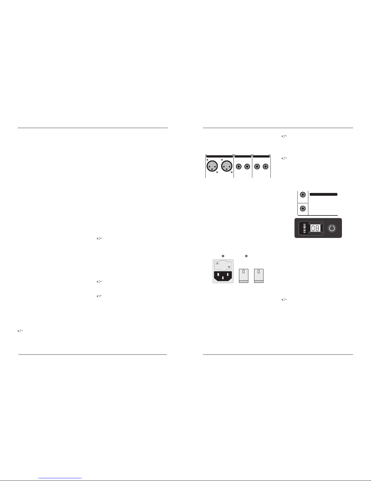
Fig . 2.14 Ma in mix ou tputs , Alt 3-4 ou tputs a nd
con trol ro om outp uts
2.4 .2 Voltag e suppl y, phant om powe r and fus e
Fig . 2.15: Vo ltage s upply a nd fuse
3.DIGITAL EFFECTS PROCESSOR
PROGRAM
(PUSH)
PHONES
FX
FOOTSW
24 -BIT MULTI- FX PROCESSOR
00 SMALL HALL
03 MID H ALL
06 BIG H ALL
09 CHU RCH
10 SMA LL ROOM
13 MID R OOM
16 BIG R OOM
19 CHA PEL
20 PLAT E
27 SPR ING
30 GATE D REV
36 REVERSE
40 EAR LY REFL
44 AMB IENCE
48 STAD IUM
49 AM BIENC E FX
50 DE LAY
59 EC HO
60 CH ORUS
66 FL ANGER
70 PH ASER
74 PI TCH SHI FT
80 CHORUS & REV ERB
82 FL ANGER & R EVERB
84 PH ASER & RE VERB
86 PI TCH & REV ERB
88 DE LAY & REVER B
90 DE LAY & GATED
91 DE LAY & REVER SE
92 DE LAY & CHORU S
94 DE LAY & FLANG ER
96 DE LAY & PHASE R
98 DE LAY & PITCH
LEV EL
You ca n select t he effect p reset by t urning th e PROGRAM
contr ol. The disp lay flashe s the number o f the curren t preset.
To reca ll the selec ted pre set, p ress th e butt on; th e flash ing
stops . You c an als o reca ll the selec ted pr eset w ith th e foot
switc h.
PRO GRAM
On t he foll owing page, you wil l find an il lustrat ion
show ing how to co nnect you r foot swit ch corre ctly.
The LED level mater on the effects module should display a
sufficiently high level. Take care to ensure that the clip LED only
lights up at peak levels. I f it is lit constantly, you are overloading
the effects processor and this could cause unpleasant distortion.
The FX control (AUX SEND 2) determines the level that reaches
the e ffects m odule .
Fig . 3.1: Di gital e ffect s modul e
CLIP
-
3
-
6
-
10
-
15
-
20
24-BIT DUAL ENGI NE DSP
LEVEL
24-BIT A/D & D/A CO NVERTE R
Page 5
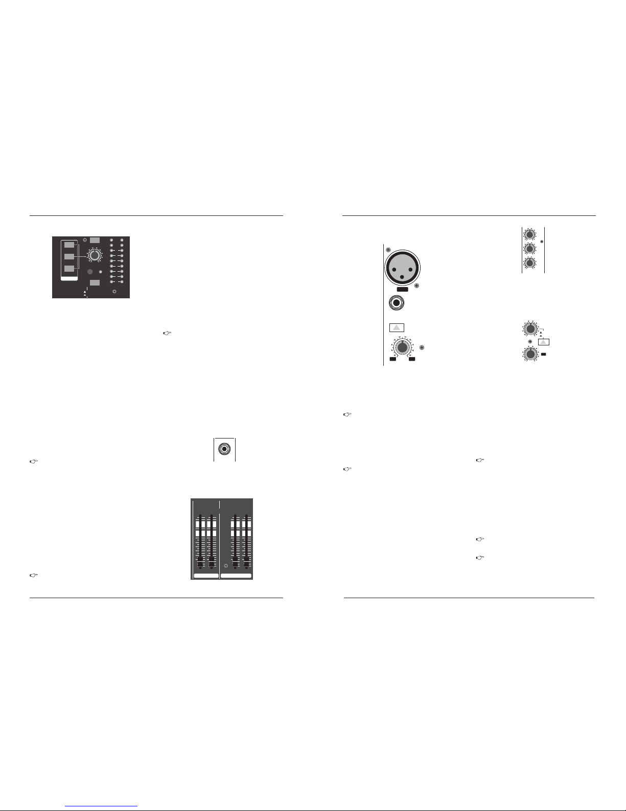
Eac h mono i nput c hanne l offe rs a bal anced m icro phon e
inp ut via t he XLR c onnec tor an d also f eatu res swi tcha ble
+48 V p hant om pow er supp ly for con dense r micr opho nes.
The M X prea mps pr ovide u ndis tort ed and no ised -fre e gain
as is t ypic ally k nown on ly fro m cost ly out board p ream ps.
Each mo no input als o feature s a balance d line input o n a
1/4"co nnector . Un balance d devices ( mono jacks ) can also
be conn ected to th ese inputs .
3
Please mute your play back system before you activ e
the phantom power supply to prevent switch-on thump
being directed to your loudspea kers. Please also n ote
the instructions in chapte r 2.4.2 “Voltage supply,
phantom power and fuse”.
LIN EIN
MIC
MX S e r ies M i xer
The TRA CK switch routed, th e signal from the TRACK IN
connectors t o the level metre, the CONT ROL ROOM OUT
outputs and the PHONES connecto r----this is a simple way
to check recorded signal s via monitor speakers or headphones.
Si mil arly, the ALT 3 -4 sw itc h rou tes t he si gnal from the
Al t 3-4 b us to t he sa me pa th fo r mon ito ring purp ose s.
The MAIN MIX switch sends the main mix signal to the abovementioned outputs and to the level metre.
ALT 3-4
MAI N MIX
Use this control to set control room output level and headphone
volume respectively.
PHO NES/C TRL (ROO M)
Whe n the 2-T RACK TO MA IN swit ch is dep resse d, the 2tra ck inpu t is rout ed to the m ain thu s serves as an a dditional
inp ut for ta pe mach ines. You c an also c onnec t MIDI fu rther
pro cessi ng. At the s ame tim e, this s witch d isabl es the ma in
mix t o tape ou tput li nk.
2-T RACK TO MA IN
POW ER
The blue POWER LE D indicates that the de vice is switched
on.
6
2-T RACK
MX S e r ies M i xer
ple ase re membe r tha t you c an onl y use e ither the
mic ropho ne o r th e lin e in put of a chan nel at an y
one t ime. You c an neve r use bo th sim ultan eousl y!
The mono channels of the mixing consoles have a high-slope
LOW CUT filter for eliminat ing unwanted, low-frequenty signal
components (75 Hz, 18 dB/octav e).
LOW C UT
TRI M
Use the T RIM contro l to adjus t the input gain. This control
should al ways be turned fu lly counterc lockwise whe never you
connec t or disconnect a si gnal source to one of th e inputs.
All mono input channels include a 3-band equalizer. All bands
provide boost or cut of up to 15 dB. In the central position, the
equalizer is inactive.
2.1 .3 Aux sen ds
The circuitry of t he British EQs is based on the technology
used in the bast-known top-of-the-line co nsoles and provi ding
a warm sound without any unwanted side effects. The result are
extremely musical equalizes which, unlik e simple equalizers,
cause no side effects such as phase shifting or bandw idth
_
lim itati on, eve n with ex treme g ain set tings o f +15 dB.
The upper (HI) and the lower b and (LO) are she lving filters
that incre ase or decrease all frequencies abov e or below their
cut-off frequen cy. The cut-off freq uencies of the upper and
lower band are 12 kHz and 80 Hz respecti vely. The mid band is
configure d as a peak filter with a centre freq uency of 2.5kHz
Aux sends take signals via a control from one or more channels
and sum these signals to a so-called bus. This bus signal is sent
to an aux send connector and then routed, for example, to an active
monitor speaker or an external effects device. The return from an
external effect device can then be brought back into the console
via t he aux re turn co nnect ors.
For situations which require effects processing, the aux sends are
usually switched post-fader so that the effects volume in a channel
corresponds to the position of the channel fader. if this were not the
channel would remain audible even when the fader is turned to zero.
When setting up a monitor mix, the aux sends are generally switched
to pre-fader, i.e. they operate independently of the position of the
cha nnel fa der.
Both aux sends are mono, are sourced after the equalizer and
offer up to +15dB gain.
PFL
SOL O
Also a rule, s olo signal s are monito red via the co ntrol room
outpu t and he adphone s conne ctor and are dis played by the
level meters. I f a also swi tch is pre ssed, the signals f rom the
tape i nput, Alt 3- 4 and main mix are bl ocked fro m the cont rol
room ou tputs, the h eadphone c onnecto r and the level m eter.
+48 V
LEV EL METER
Th e hig h-pr oci sion leve l met er ac cur atel y dis pla ys th e
ap prop ria te si gnal leve l.
When recording to a digital device, the recorder’s peak metre
should mot exceed 0 dB. This is because, unlike analog recordings,
slightly excessive levels can create unpleasant digital distortion.
LEV EL SETTI NG
The red “+48V” LED lights when the phantom power supply
is switch on. The phantom power supply is necessary for condenser
microphones and is activated using the switch on the rear of the
device.
sys tem sta biliz ation .
Please do n ot connect micr ophones to the mix er
(or th e stagebo x/wellbo x) while the phant om power
supply i s switched on. Co nnect microp hones befor e
you swit ch on the power sup ply. In addition , t he
monito r/PA loud speakers , shou ld be muted befor e
you act ivate the p hantom pow er supply. Afte r
switch ing on, wait approx. One mi nute to allow for
When r ecordi ng to an anal og devic e, the VU met ers of the
reco rding mac hine shoul d r each appr ox. +3 dB with lowfreq uency signal s (e. g. Kic k dru m). Du e to their inerti a VU
mete rs tend t o displa y too low a signal s level at freque ncies
abov e 1 kHz. T his is wh y ,for ex ample, a Hi-Hat should only
be dr iven as f ar as -10 dB. Sna re drums should b e drive n to
app rox. 0 dB .
To activate the PFL function, depress the MODE switch. The
PFL function should, as a rule, be used for gain setting purposes.
The signal is sourced pre-fader and assigned to the mono PFL
bus. In the “PFL”setting, only the left side of the peak meter
operates. Drive the individual channels to the 0 dB mark of the
VU me ter.
When the MODE switch is not depressed, the stereo solo bus
is activate. Solo is short for “Solo In Place”. This is the customary
method for listening to an individual signal or to a group of signals.
As soon as a solo switch is pressed, all channels in the control
room (and headphones) that have not been selected are muted
thereby retaining stereo panning. The solo bus can carry the
output signals of the channel pan controls, the aux sends and
the stereo line inputs. The solo bus is, as a rule, switched postfad er.
MOD E
The MODE switch determi nes whether the channels'SO LO
switch o perates as P FL (Pre Fader Listen) or as solo (Solo In
Place).
The PAN control in the channel strip offers a constant
power characteristic. This means that the signal is
always at a constant level, irrespective of its position
in the stereo panorama. If the PAN control is moved
fully left or right from center, the level increases by 4
dB in that channel. This signal is not louder. For this
reason, with the solo function activated (Solo In Place),
audio signals from the channels with PAN controls that
have not be moved fully to the left or right are displayed
at a lo wer vol ume tha t in the PF L functi on.
+10 -40
MIC
+10 +60
TRIM
dB/dBu
LOW CUT
75Hz
18 dB/O ct
LINE IN
BAL
OR
UNBAL
1
0
-15 +15
0
-15 +15
0
-15 +15
HIGH
12 KHz
EQ
MID
2.5 KHz
LOW
80 Hz
0
- +15
8
2
0
-8+15
AUX1
FX
POST
PRE
- +15
8
3 4
MODE
SOLO (NORMA L)
PFL (LEVEL S ET)
L R
MAIN SOLO P FL
MAIN MIX
ALT 3-4
2-TRACK
PHONES/ CTRL R
SOURC E
2TK TO MAIN M IX
POWER + 48 V
CLIP
10
5
2
0
2
5
20
2.1 Mono channels
2.1 .1 Micr ophon e and lin e input s
Fig . 2.1: Co nnect ors and c ontro ls of mic /line i nputs
Fig . 2.2: Pa noram a and rou ting co ntrol s
Fig . 2.3: Th e AUX SEND c ontro ls in the c hanne l strip s
If y ou pre ss th e MUT E/ALT 3 -4 sw itc h, aux send 1
is m uted , pro vide d tha t it is s witc hed p ost -fad er.
How eve r, thi s does not af fec t the a ux sen d 2
Aux send 1 can be switched pre-fader and is thus particularl y
suitable for settin g up monitor mixes.
AUX 1 ( MON)
PRE
Whe n the P RE swi tch is p ress ed, a ux sen d 1 is sou rced
pre -fad er.
The aux send labeled FX is for sending to effects devices and
is thus set up to be post-fader.
Aux 2 ( FX)
If you wish to us e the internal ef fects proces sor, the
STEREO AUX RETURN 2 connector s should not be is
use.
You can also connect an external effects processor to
aux send 2, however the internal effects module will be
muted.
2.3 .6 Leve l meter a nd moni torin g
Fig . 2.11: Con trol ro om/ph ones se ction , level m eter
The peak metr es of y our X ENYX disp lay t he le vel
vir tua lly inde pen dent of freq uen cy. A reco rdin g
lev el of 0 dB is r eco mmen ded f or all sign al ty pes.
MAI N SOLO
The MAIN SOL O LED lights up as soo n as a channel or aux
send sol o switch is pres sed. The MODE swi tch also has to be
set at “solo”.
The PFL LED indicates that the peak metre is set to PFL mode.
PFL
PHO NES
You can connect headphone to this TRS con nector. The
signal on the PHONES conn ection is sourc ed from the con trol
1/4"
roo m outpu t.
PHONE S
ALT 3-4 MAIN M IX
10
0
10
15
20
25
30
40
60
8
10
0
10
15
20
25
30
40
60
8
10
0
10
15
20
25
30
40
60
8
10
0
10
15
20
25
30
40
60
8
3 4 L R
Fig . 2.12: P HONES c onnec tor
2.3 .7 Alt 3-4 a nd main m ix fade r
Fig . 2.13: A lt 3-4 an d main mi x fader
2.1 .2 Equa lizer
Page 6
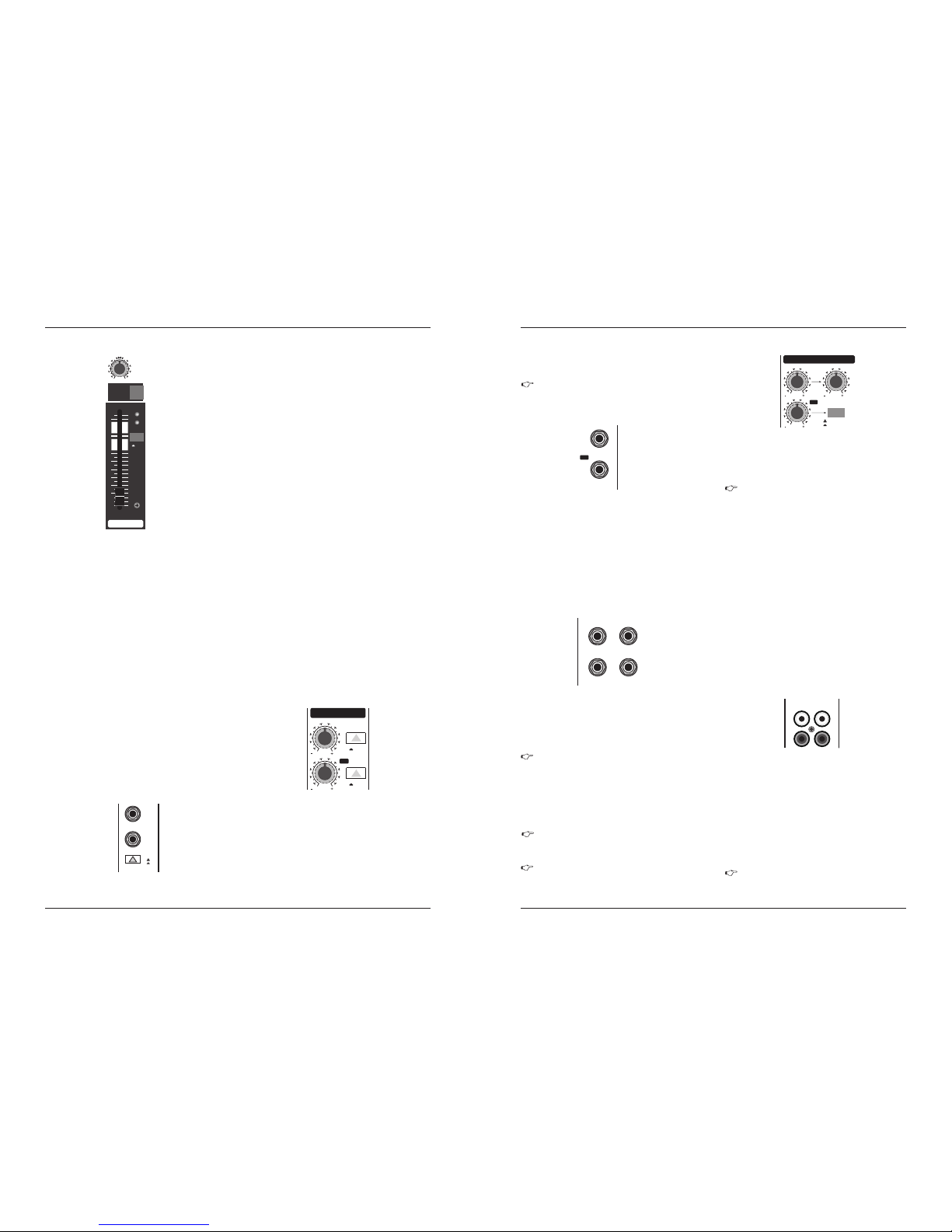
2-T RACK IN PUT
2-T RACK OU TPUT
These connec tors are wired in parallel with MAI N OUT and
carry the main mix signal (unbalanced).Connect the 2-TRACK
OUTPUT to the inputs of your recording device. The final output
level can be adjusted via the high-precision MAIN MIX fader.
If yo u conn ect a c ompre ssor or a noi se gate a fter
the 2 -tra ck out put, t he fad ers wi ll pr obabl y not b e
abl e to cre ate a s atisf acto ry fad e-ou t effe ct.
The 2 -TRAC K INPU T RCA connec tors are p rovide d for
conn ecting a 2 track ma chine ( e.g. DAT re corder ). They ca n
also be used as st ereo line input . Alte rnativ ely, th e out put
sign al of a seco nd MX Seri es Mixin g can als o be conne cted.
If you c onnec t a hi fi amp lifier w ith a sou rce sele ction s witch
to th e 2-TRA CK INPU T, you can easil y switc h betwe en
addi tiona l source s (e.g. Ca ssette r ecorde r, CD playe r, etc.).
Each stereo c hannel has two bal anced line level in put on
1/4"connectors for left and right channe ls. If only the connector
marked "L " is used, the channel operates in mono. Stere o
channels are designed to handle typica l line level signals.
Bot h input c an also b e used wi th unba lance d jacks .
The equalizer of the stereo channel is, of course, stereo. The
filter characteristics and crossover frequencies are the same as
those of the mono channels. A stereo equalizer is always preferable
to mono equalizers if frequency correction of a stereo signal is
needed. There is often a discrepancy between the settings of the
left and the right channels when using separate equalizers.
In principl e, the aux sends of the ster eo channels func tion in
just the same wa y as those of the mono chann els. As aux send
paths are alw ays mono, the signa l on a stereo channel is fir st
summed to mon o before it reaches it re aches the aux bus.
2.2 .3 Aux sen ds ster eo chan nels
2.2 .2 Equa lizer s tereo c hanne ls
LEV EL
2.2 .4 rout ing swi tch, so lo and ch annel f ader
The fun ction of th e BAL(ANC E) contr ol corres ponds to th e
PAN cont rol in the mo no channe ls.
The balance control determines the relative proportion between
the left and right input signals before both signals are routed to the
main stereo mix bus.
The MU TE/ALT 3-4 s witch , the MUTE -LED, t he CLP-L ED,
the SO LO swit ch and the c hannel f ader fu nction i n the sam e
way as t he mono ch annel s.
2.3 C onnec tor pan el and ma in sect ion
Whereas it was usefu l to trace the signa l flow fro m top to
bottom it order to gain an understanding of the channel strips ,
we now look at the mixing console from left to right. The signa ls
are, so to speaker, collected from the same point on each of the
channel strips and then routed to the main section all togeth er.
You can u se the SO LO swit ch to sep arate ly moni tor the
aux s ends vi a the CON TROL ROO M/PHO NES out puts and
che ck thes e with th e level m etres .
SOL O
If you wa nt to monito r the signal t he of just one AU X
bus, no ne of the othe r SOLO SWITC HES shoul d be
press ed and the MOD E switch mu st be in the SOLO
posit ion (not pr essed dow n).
AUX S END 1
AUX S END 2
STE REO AUX RE TURN 1
5
For level matchi ng, the stereo inputs feat ure a LEVEL switch
which selec ts between +4 dBu and -10 dBV. At -10 dBV (homerecordin g leve l), th e input is more sensitive than at +4 d Bu
(st udio le vel).
BAL
If you use aux send 1 p re-fader, you would u sually connect
the AUX SEND 1conn ector to monitors via a power amp (or an
active monitor system). If you use aux send 1 post-fader,proceed
as de scrib ed unde r aux sen d 2.
The AUX SEND 2 connector outputs the signal you picked up
from the individual channels using the FX control. You can connect
this to the input of an effects mix is created, the processed signal
can then be routed from the effects device output back into the
STE REO AUX RE TURN co nnect ors.
The
return path for the effects mix generated using the post-fader aux send.
This is where you connect the output signal of the external effects device.
If only the connector is used, the AUX RETURN automatically operates
STEREO AUX RETURN 1 connectors generally serve as the
in mono.
MX S e r ies M i xer
4
The PAN control determines the position of the channel signal
within the stereo image. This control features a constant-power
characteristic, which means the signal is always maintained at a
constant level, irrespective o position in the stereo panorama.
You can use the MUTE/ALT 3-4 switch t o driver the channel
from the main mix bus to the Alt 3-4 bus. This mutes the channel
from the main mix.
The MUTE LED indicates that the relevant channel is diverted
to the submix (Alt 3-4 bus).
MUT E/ALT 3-4
MUT E-LED
CLI P-LED
The CLIP LED lights up when the input signal is driver too high.
In this case , turn down the TRIM control and, if necessary, check
the setting of the channel EQ.
PAN
MX S e r ies M i xer
If y ou wi sh to use t he in ter nal e ffec ts p roce sso r,
no c onn ecto rs s houl d be p lug ged i nto STE REO
AU X RET URN 2 .
2.1 .4 Rout ing swi tch, so lo and ch annel f ader
L R
PAN
1
MUTE
ALT 3-4
1
dB10MUTE
CLIP
0
10
15
20
25
30
40
60
8
SOLO
A channel signal is routed to aux send bus 1 if the Aux 1 control
is turned up on the corresponding channel.
The AUX SEND cont rol MON acts as mast er control for au x
send 1 and det ermines the le vel of the summed si gnal
AUX S END 1 (MO N)
Similarl y, the FX control (AU X SEND 2) determines the lev el
for aux send 2.
AUX S END 2 (FX )
0
15
8
0
15
8
1
2
FX
AUX SEND S
SOLO
SOLO
1
2
FX
AUX SEN DS
LEFT /MONO RI GHT
1
2
RETU RNSSTERE O AUX
0
8
0
8
1
2
0
8
1
STEREO AU X RETUR NS
MAIN MIX
ALT 3-4
TO AUX
SEND 1
88
8
FX
In this in stance, the F X control of the c hannel bein g
used as an eff ects return sh ould be turned fu lly
count erclockw ise, o therwise feed back p roblems
could occur!
STEREO AUX RETURN 1 is a stereo control which determines
is used as effects return, you can add the effects signal to any
STE REO AUX RE TURN 1
In thi s instan ce, the e ffects d evice sh ould be se t at
100% e ffect .
STE REO AUX RE TURN MO N
Mon itor mi x with ef fect
You can now use the STEREO AUX RETURN MON control to
adjust the level of the effects signal rout ed to the monitor mix.
The STEREO AUX RETURN 2 control determines the level of
signals fed into the AUX RETURN 2 connectors which are routed
to the main mix.
STE REO AUX RE TURN 2 (F X)
MAI N MIX/A LT 3-4
The MAIN MIX/ALT 3-4 switch routes the signal connec ted to
STEREO AUX RETURN 2 to either main mix (not pres sed) or
“dry” c hanne l signa l .
Th e STER EO AU X RET URN M ON con tro l has a speci al
fu ncti on: i t ca n be us ed t o add an ef fect to a m onit or m ix.
Fo r exam ple :
In this instance, the effect device should be set up as follows:
AUX SEND 2 is connected to the L/Mono input of your effects
device, while its outputs are connected to STEREO AUX RETURN
1. Connect the amplifier of your monitor system to AUX SEND 1.
The AUX SEND 1 master control determines the volume of the
mon itor mi x.
sub mix (Al t 3-4, pr essed ).
STE REO AUX RE TURN 2
You c an al so us e the se co nne ctor s as a ddit ion al
li ne in puts .
The STEREO AUX RETURN 2 connectors serve as the return
path for the effec ts mix generated using the FX control. If these
connectors al ready function as a dditional inputs, you can route
the effects signal back into the console via a different chan nel,
with the added benefit that the channel EQ can be used to adjust
the frequency of the effects signal.
SOL O
The channel fader determines the level of the channel signal in
the main mix (or submix).
T he SOLO swit ch is used to route the ch annelsign al to the
solo bu s (Solo In Pla ce) or to the PF L bus (Pre Fade r Listen).
This enab les you to monito r a channel signal w ithout affect ing
the ma in output s ignal. The signal yo u hear is s ourced eit her
before (P FL, mono) or afte r (solo, stereo ) both the pan contro l
and the channel fad er (see cha pter 2.3.6 “ Level meters and
mon itori ng” ).
LINE IN 7 /8
+4
-10
MONO
L
R
LEVEL
BAL
OR
UNBAL
2.2 S tereo c hanne ls
2.2 .1 Chan nel inp uts
Fig . 2.5: St ereo ch annel i nputs a nd LEVE L switch
Fig . 2.4: Pa noram a and rou ting co ntrol s
2.3 .1 Aux sen ds 1 and 2
Fig . 2.6: AUX S END con trol s of t he main s ectio n
2.3 .2 Aux sen d conne ctors 1 a nd 2
2.3 .3 Ster eo aux re turn co nnect ors
Fig . 2.8: St ereo au x retur n conne ctors
Fig . 2.7: Aux s end con necto rs
2.3 .4 Ster eo aux re turn
Fig . 2.9: St ereo au x retur n contr ols
2.3 .5 Tape inp ut/ta pe outp ut
Fig . 2.10: 2 -trac k conne ctors
INPUTLOUTPUT
2TK TO MAI N MIX
L
RR
 Loading...