

Page 1
2017 07-18
www.pronktech.com 800-541-9802
Page 1
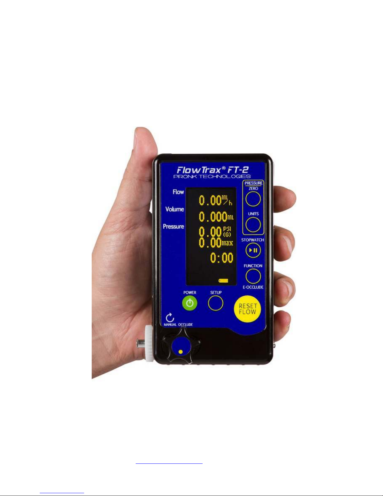
Flow Trax
®
Infusion Device Analyzer
Operator’s Manual
Pronk Technologies
©2015
Page 2
2017 07-18
www.pronktech.com 800-541-9802
Page 2
Compliant products conforming to the relevant standards and directives required for CE
have a CE Mark label, as shown below, affixed to the unit. CE Marked products also comply
with the WEEE directive for category 9 Monitoring and Control Instrumentation products.
Do not dispose of this product as unsorted waste. To dispose, contact Pronk Technologies
[email protected]. A Return Material Authorization will be issued to return the
at
unit for disposal.
FlowTrax, Pronk, and Pronk Technologies are trademarks of Pronk Technologies Inc.
©2012 Pronk Technologies Inc. All rights reserved.
Pronk Technologies
©2015
Page 3

2017 07-18
www.pronktech.com 800-541-9802
Page 3
This Operators Manual relates to FlowTrax software version 1.6. The user can ve rify the s/w versi on they have on
their FlowTrax by press and hold of the setup key. Version number is located in upper left hand corner.
This product is intended for testing purpose only and is not used in diagnostics, treatment or any other capacity
where they would come in contact with a patient.
The device shall only be used with the AC-DC adaptor provided or with AA Alkaline or Lithium batteries.
Operate thi s product using only acc essories pr ovided b y P ronk Technologies.
If this equipment is used in a manner not specified by the Pronk Technologies, the protection provided by the
equipment may be impaired.
Service and calibration must be performed by Pronk Technologies or a designated service organization approved by
Pronk Te chnologies. Verify proper service and calibration by reviewing certification document returned with the
device.
Pronk Technologies
©2015
Page 4

2017 07-18
www.pronktech.com 800-541-9802
Page 4
Table of Contents
Accessories and Symbols………………………………………………... 5
Introduction…………………………………………………………....... 6
Quick Start………………………………………………………………. 6
Detailed Operating Instructions……………………………………….. 7
Priming…………………………………………………………………... 7
Flow & Volume Measurements………………………………………… 8
Trending Flow and Volume ……………………………………………. 9
Occlusion Testing……………………………………………………….. 9
Air-In-Line Testing……………………………………………………... 10
Stopwatch, Pressure Meter Measurements............................................ 10
Temperature Measurements………………………………………….... 10
Important Application Notes…………………………………………... 10
Page
Contamination of Flow Trax Fluid Path……………………………… 11
Routine Maintenance…………………………………………………… 11
Preventative and Routine Maintenance Chart……………………….. 13
Troubleshooting Tips…………………………………………………… 14
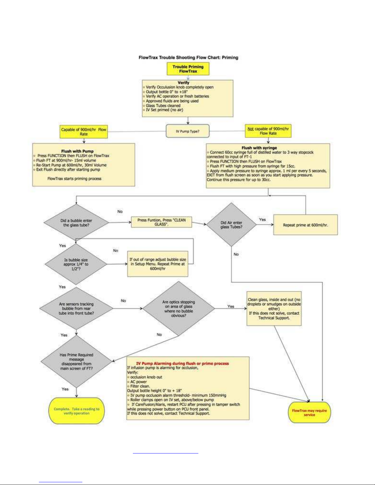
Troubleshooting Flow Chart- Priming………………………………... 15
IV Pump Manufacturer Height requirements Chart………………… 16
HydroBalance Setup and Use………………………………………….. 16
DataSnap Electronic Data Transfer and Control……………………. 16
Serial Communications Protocol……………………………………… 19
Updating Software……………………………………………………… 21
Technical Specifications………………………………………………… 22
Flow Rate vs. Time Required Chart………………………………….... 23
Warranty and Service Information…………………………………..... 24
Pronk Technologies
©2015
Page 5
2017 07-18
www.pronktech.com 800-541-9802
Page 5
Accessories
Standard
Accessories
6VDC/1.8 amp Power
Supply
Spare Filter Screen
Assy.
Optional
Accessories
IV pole mount bracket/clamp assembly. Provides a mechanism for clamping
NOTE: Available for S/N 1000 or above
Automatically pivots IV bag in use to maintain fluid height relative to IV
accuracy of testing.
IV bags for
HydroBalance
Set of four Kangaroo 1000ml fluid bags for use with IV pump testing.
Optimal size / volume for use with Hydro B alance.
FlowTrax DataSnap serial port accessories for data collection and bi-
DVD with DataSnap installatio n instructions.
FlowTrax Stereo To
USB Cable
FlowTrax serial plug to USB adapter cable.
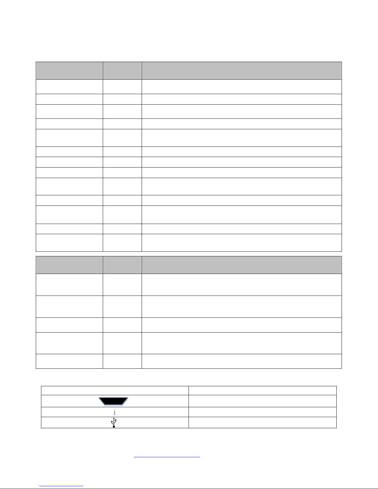
Connector panel symbol
Function
Serial Port
YSI 400 Temperature Probe port
USB port
P/N Description
501-0701 6VDC/1.8 amp Power Supply for SimCube; OxSim - US Type A Plug
Carrying Case 501-0806 Carrying case for FlowTrax. Includes pockets for accessories.
501-9919 2 each Replacement filters, installs inside Input Luer.
High Pressure Fitting 501-9910 Input connector utilized for Pressure or vacuum testing.
Syringe Assembly 501-9912
3 Way Stopcock 102-4023 3 way sto p co c k with lue r fitti ngs. Attac hes to input of FlowTrax.
Output Hose 501-9908 Clear tubi ng. Connects t o output Luer of FlowTrax.
USB Cable 501-9905 USB adapter cable for connecting FlowTrax to PC for software updates.
Temperature Probe
Extension Cable
Bottle Brush 501-9913 Utilized to clean FlowTrax sample tube.
501-0404
60cc Syringe and 3-way stopcock. U tiliz e d for priming FlowTrax in place of
IV pump or to divert air-in-line into syringe by inserting at input at FlowTrax.
Adapter connects to FlowTrax and YSI temperature probe.
probe not sold by Pronk Technologies
Note: Temp.
Cleaning Solution
Assembly
Quick Reference Guide 501-0610 Quick reference guide for getting up and runnin g quickly.
User Guide DVD 501-0611
IV Pole M ount 501-9909
HydroBalance™ 501-9914
DataSnap 601-FT01
501-9906 Used to clean sample tube. Contains Windex
Training video s on utilizing FlowTrax. Includes User Manual, DataSnap
software
P/N
FlowTrax to IV pole or bench top. Pivots FlowTrax 90 degrees when needed.
pump to meet IV Pump Manufacturer height requirements and improve
501-9915
directional communications. Includes (1) Stereo to USB cable, (1) FlowTrax
501-9918
Description
®.
Symbol Descriptions:
Pronk Technologies
©2015
Page 6
2017 07-18
www.pronktech.com 800-541-9802
Page 6
Flow Trax FT-2
Operation
Instructions
Introduction
The FlowTrax is quick to set up, easy to use and ready to go where you need to be. Your FlowTrax comes with
a small 6VDC/1.8 amp power supply, a carrying case, two spare filter screen assemblies, a high pressure fitt i n g,
syringe, 3 wa y s to p co c k, o utp ut ho se , U SB cable, T emperature Probe extension cable, bottle brush, flush bottle,
bottle of glass tube cleaner, Operators’ manual, Quick Reference Guide and a training video.
Quick Start: (NOTE:
priming has begun.)
Use Distilled, Deionized wat er o nly.
Prime/purge the IV set before connecting to FlowTrax.
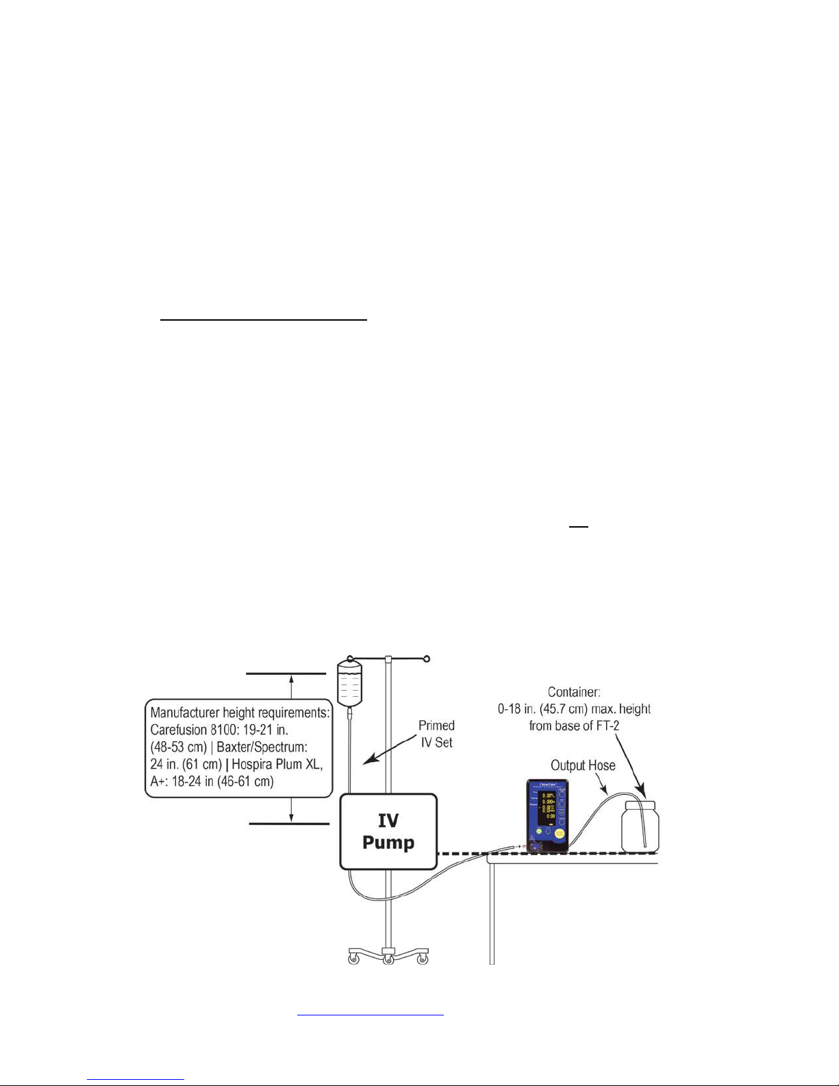
Setup FlowTrax vertically on a level bench / surface, or attach to IV pole per figure 1.
If FlowTrax has been unuse d for several hours o r longer (overnight, for example), run 600ml/hr or
more with 3 0ml of volume through FlowT ra x to condition glass tube surface. If bubble is “sticking”
or “draggin g” on inside o f gla ss, tr y using “CLE AN GL ASS” F unctio n, t hen ru n a volume of 20ml of
distilled fluid through FlowTrax and re-Prime. If bubble s ticking persists, clean gla ss with bottle brush
and cleaner provided (see Routine Maintenance section).
Flush FlowTrax (by selecting FUNCTION then FLUSH and running pump at 900+ml/hr for
approximately 20ml Volume.
Prime FlowTrax b y exiting FLUSH Screen (at approximately 600ml/hr) –
own bubble (approx. 3/8”) during priming process for tracking purposes.
Place output b ottle at the sa me hei ght as FlowTrax. Output bottle should not be below FlowTrax, and
should not be more than 18” above FlowTrax output fitting (right side).
Clean Glass once a month with cleaning solution and bottle brush provided, once a week if run ning
very low rate tests.
FlowTrax will generate a tracking bubble itself, once flushed and
FlowTrax
Figure 1
Setup Diagram
will generate its
Pronk Technologies
©2015
Page 7

2017 07-18
www.pronktech.com 800-541-9802
Page 7
Detailed Operating Instructions:
1) Power up the Flow Trax:
Plug the FlowTrax into an AC socke t via the small power supply provided. Pres s the green POWER button on the
front of t he F l o wTra x to tur n it o n. Alternatively you can use 2 AA batteries to power Flo wTrax. To install the
batteries use the symbols inside the battery compartment for or ientation. To remove batteries use your finger or
flat object to pull the battery out of the compartment.
2) Test Solution:
Use only distilled, Deionized water with FlowTrax for proper operation, accuracy and longevity of the device.
3) Output bottle:
Place output bottle at the same heig ht as FlowTrax or up to 18” above. The output bottle should not be below the
level of FlowTrax.
4) Accelerometer (TILT) Check:
FlowTrax has a built in accelero meter utilized to detect when the FlowTrax is tilted. At power up it is impor tant to
verify you do NOT see the “TILT” message on the display. If a TILT message is displayed, v e r i fy FlowT rax is on
a level surface in the upright or horizontal position. This message must be cleared to ensure the best accuracy of
the readings.
NOTE: If the “TILT” message won’t clear, and you are confident that the FlowT r ax is on a very level surface,
press SETUP, MORE, CHK TILT. Press ZERO in the upper right corner to calibrate the accelerometer to the
level surface yo u are wor ki ng wit h.
5) Priming Flow Trax:
Description: Flo wTrax will tell you if it requires a pri me. If Flo wTra x posts “PRIME REQUIRED”, in the
flow/volume segments of the display, a new prime is required. Each time you press “RESET FLOW” it will scan
the glass tubes to determine if the conditions of the visible fluid column are adequate for accurate flow/volume
measureme nts. Al ways primed/purge your IV Set of any air bubbles before connecting to Flo wTrax, as this sc an
can only evaluate the conditions inside the FlowT rax and cannot see air coming in from the IV set. These air
bubbles can reach the optics during a reading and cause errors.
FlowTrax flow rate and volu me testing ge nera lly requires a new prime under the follo wing conditions: each time
the glass has been cleaned, if Flo wTrax has been s tored (no t in use) for more t han a few ho urs or , in some cases,
when a new IV set has is attached to F l o wTra x (if the IV set has not been primed/purged of air). Once an initial
prime has been completed on FlowTr ax, it should not need to be repeated during a normal work day unless air is
introduced into the FlowTrax.
There are two methods to prime FlowTrax depending on what type of pump you are testing and how you have
configured your setup. Choose the appropriate method below that best matches the pump you’re testing.
NOTE 1: When setti ng up FlowTr ax at the beginni ng of each day, a ZERO pressure should be performed with
FlowTrax void of fluid (Use “Clean Glass Function”) and nothing connected to the input fitting before performing
the “FLUSH” and “PRIME” steps to follow. See “Occlusion Testing” section for more information.
NOTE 2: ALWAYS prime/purge the IV set into a collection container before atta ching it to the FlowT r ax fitting
to reduce priming time and to optimize performance.
a) Priming with Infusion Device (capable of rates 600ml/hr or more)
• With FlowTrax upright (vertical) and level, attac h primed/purged IV set to the input (left side)
fitting of FlowTrax.
• Flush FlowTrax by selecting FUNCTION then FLUSH and running pump at 900+ml/hr for
approximately 20ml Volume.
• Leave FlowTrax on the FLUSH screen, reprogram IV Pump for 600ml/hr and 20ml Volume.
• Restart IV pump.
Pronk Technologies
©2015
Page 8

2017 07-18
www.pronktech.com 800-541-9802
Page 8
• Prime FlowTrax by exiting FLUSH Screen (with pump running approximately 600ml/hr) –
NOTE: FlowTrax will generate its own bubble (approx. 3/8”) during priming process for
tracking purposes.
• Continue this rate until “PRIME REQUIRED” message is replaced with actual flow rate
numbers in the FLOW section of the screen. The Volume section of the screen will change
from “PRIME REQUIRED” to “RESET FLOW TO START VOL” when priming has
completed.
• Press RESET FLOW just prior to starting the infusion pump to zero Flow, Volume, Max
pressure and timer.
b) Priming with syringe and 3-way stopcock (when testing units not capable of 600ml/hr or
higher rates)
• Fill 60cc syringe with 50+ cc of distilled water.
• FlowTrax upright (vertical) and level
• Attach syringe to 3-way stopcock, then attach 3-way stopcock to input (left side) fitting of
FlowTrax. Position the 3-way stopcock valve to allow flow from syringe into FlowTrax.
• Flush FlowTrax (by se lecting FUN CTION then F LUSH) and usi ng a high spee d, hard push o f
the syringe for approximately 20ml Volume.
• Leave FlowTrax on the FLUSH screen, depress syringe plunger at a low speed for
approximately 20ml Volume.
• Continue this rate until “PRIME REQUIRED” message goes away in the FLOW sec tion of the
screen and is replaced with rate average numbers. The Volume section of the screen will
change from “PRIME REQUIRED” to “RESET FLOW TO START VOL” when priming ha s
completed.
NOTE 3: If FlowTrax has been sitting unused for several days with water in the tubes, run for 5-10 minutes at a
rate of 300ml/hr (syringe pump) or 600+ml/hr (IV Pump) before using for measurement. If FlowTrax has been
sitting unused for a few days or more dry, it may be necessary to do a CLEAN GLASS process (See maintenance
section) for best results.
6) Flow and Volume Measurements:
a) Attach IV set to input of Fl o wT r a x , or to remaining port on 3 way stopcock. ALWAYS prime/p urge the I V
set into a collection container before attaching it to the FlowTrax fitting to reduce priming time and to
optimize performance.
b) If a 3 way stopcock is still i nstalled , po sition the 3 way stopco ck valve to allo w flow fro m the infusio n device
into FlowTrax and not into the syringe.
c) Configure the infusion device for the desired flow/volume.
d) Press the RESET FLOW button to reset both flow rate and volume numbers on the FlowTrax just prior to
starting infusion device for testing.
e) Start IV pump.
f) The FlowTrax will automatically begin flow and volume measurement when it se nses flow from the IV
pump.
NOTE: It is not necessary to “stop” the FlowTrax at the end of a test. FlowTrax will capture an accurate total
volume delivered and post an average Flow Rate at the end of a test without user interaction. If KVO (Keep Vein
Open) feature on the IV pump is enabled on the infusion device being tested, Volume, and in some cases, the
Flow Rate measurement may be affected.
Very Low Rate Testing:
NOTE: When performing flow and or volume tests involving Flow Rates below 20ml/hr, flushi ng and priming
still must be performed with FlowTrax vertical (upr ight).
a) After Flo wTrax is flu she d and primed, lay FlowTrax on i ts b a ck (horizontal) so that the buttons are facing the
ceiling for the most accurate results at these lower rates. NOTE: You do not need to remove the IV bracket
from the back cover. It is acceptable for FlowTrax to lean on one side when horizontal.
Pronk Technologies
©2015
Page 9

2017 07-18
www.pronktech.com 800-541-9802
Page 9
b) If FlowTrax is mounted to an IV pole, turn it 90 degrees or remove from pole clamp and lay it on its back on
flat/level surface.
c) Run the pump being tested using its maxi mu m r at e it can be programmed for while observing the glas s tubes.
Make sure that there are no tiny bubbles in the front glass tube that are not travelling at t he sa me spe ed a s the
primary tra cking bubb le. These tiny bubbles can interfere with the FlowTrax measurements, and it may be
necessary to momentarily tilt the FlowTrax in order to cause the tiny bubble to attach to the primary /
tracking bubble before starting a low rate test.
d) Verify FlowTrax does NOT display a “TILT” message before starting a test.
e) FlowTrax shoul d be used in an upright (vertical) position rates above 20ml/hr and for priming.
7) Trending:
NOTE: The Trend screen can be used to determine Pass or Fail data from the last test performed. This is
particularly helpful for unattended tests where the user was not able to see the final results before, for example,
KVO started.
• Press the FUNCTION button, then TR END button.
• The FlowTrax captures and displays accumulated Volume and average Flow Rates at one minute
intervals for up to 14 minutes.
• Pressing RESET FLOW button will clear all trend data from previous test.
8) Occlusion Testing:
NOTE: It is not normally necessary to ZERO pre ssure repeated ly throughout the day with Fl owT rax. I n fact, if
an IV Set is attached and the output hose is above FlowTrax at the time zero is pressed, an error may be
introduced to the zero offset and subsequent occlusion measurement. Performing a pressure ZERO is
recommended at the beginning of each day unless a) there is a substantial shift in barometric pressure or b)
FlowTrax is being moved from one location to another where there is a substantial change in altitude.
a) If pressure ZERO is needed, remove i nput li ne fro m FlowTrax input fi tti ng, p ress F UN CTI ON, then CLE AN
GLASS. Press ZERO button o n Flo wT r ax . It may take a few seconds for pressure to zero. Reinstall Input
line, FLUSH and PRIME to start fluid measurements / occlusion tests.
b) Connect (if not already) IV set to FlowTrax input (left side) fitting.
c) Select desired units of measure by pressing UNITS button on FlowTrax.
d) Press RESET FLOW to zero the MAX pressure value.
e) Program infusion device for desired rate and start infusion device.
f) Slowly turn occ lusion knob on front o f Fl owT r a x clockwise until the i nfusion device alarms or the occlusio n
knob is flush with front of FlowTrax (do not over tighten).
UNITS WITH ELECTRONIC OCCLUSION (E-OCCLUDE) FEATURE:
i) Press FUNCTION key
ii) Press 40PSI Occlude soft key at bottom of screen.
iii) Program infusion device for desired rate and start infusion device.
iv) Electronic Occlusion Screen will display the maximum pressure at the top of the screen and graph
the results as the pressure in the IV pump rises, until the unit under test reaches the occlusion alarm
threshold , as shown in the figure below. MAX AT equals the total elapsed time to achieve
Occlusion. The pressure value below MAX AT is the real time pressure.
g) Document “MAX” pressure indicated on FlowTrax.
h) The last “MAX” pressure will remain on the display for 2 hours, or until “RESET FLOW” is pressed .
Pronk Technologies
©2015
Page 10

2017 07-18
www.pronktech.com 800-541-9802
Page 10
9) Air-In-Line Testing:
NOTE: To avoid air bubbles from flowing into the FlowTrax during an air-in-line test (which can force users to
re-prime), use the 3 way stopcock and syringe to exhaust the air bubble prior to reaching the input of FlowTrax.
This will allow you to run the air-in-l ine test without having to disco nnect and reconnect the IV set to the
FlowTrax.
a) Attach syringe to 3 way stopcock, attach 3 way stopcock to input (left side) fitti ng of FlowTrax.
b) Position the 3 way stopcock valve to allow flow from infusion device through to syringe and not into
FlowTrax.
c) Run the air-in-line test.
d) Either run the infusion device at a high rate until the air bubble reaches the syringe, or remove the IV set from
the infusion device mec hanism and gravity flow the air bubble until i t reaches the syringe.
e) Re-position the 3 way stopcock valve to allow flow from infusion device to FlowTrax and not into the
syringe.
Stopwatch Feature:
NOTE: The FlowTrax stopwatch feature can be used to perform any timed tests that you may need. The
stopwatch will also start when FlowTrax is se nsing flow, and stop when it senses flow has stopped.
• To start or stop the FlowTrax stopwatc h, press the Stopwatch button once on FlowTrax.
• To zero the stopwatch, press and hold the Stopwatch button until zero is observed.
10) Pressure Meter Function (-12.5 to +75 PSI):
NOTE: Flo wT ra x is not only a n infusio n device a nalyzer. It is also a full featured pressure meter. These steps
are for DRY usage of the pressure meter, and are not necessary for IV Pump occ l u si on testing
a) Place output hose in a collection container.
b) Empty all fluid from FlowTrax by pressing the FUNCTION button, and then press the CLEAN GLASS
button. The CLEAN GLASS funct ion will automatically expel water from FlowTrax.
c) Press ZERO butt on on FlowTrax for zeroing pressure.
d) Select desired units of measure by pressing UNITS button on FlowTrax.
e) T urn occlusion knob clo ckwise until knob is flush with fro nt of FlowT rax panel ( you do not need to over
tighten the knob to ob t ain an occlusion).
f) Press RESET FLOW to zero the MAX pressure.
g) Using high pressure fitting provided, or similar, co nnect to the input (left side) fitting on FlowTrax.
h) Begin pre ssure testing.
11) Temperature Measurements:
a) Connect temperature extension cable provided to temperature port on FlowTrax.
b) Connect YSI-400 probe to temperature extension cable.
c) This will automatically trigger the temp measurement to be displayed on the FlowTrax display.
d) Begin meas uring tempe rature.
12) IMPORTANT Application Notes:
Accuracy: Flo wT ra x accuracy relies on optic al sensors located on a moving carriage, which track a bubble in a
fluid column (glass tube). FlowTrax software determines the rate and volume being delivered based on the
carriage travel while tracking the bubble. T his means care must b e taken to ensur e the FlowTrax is balanced and
level relative to the bubb le inside the FlowTrax fluid column for accurate results. Avoid any tilting or leaning of
the FlowTrax. F l owT rax will post a “TILT” message in the lower left hand corner of the screen if it is not level.
In addition, extraneous air / bubbles entering F lowTr ax during pri ming or during a n actual test may introd uce
errors in the results. Ensure IV set is cleared of any air before use. For flow rates of 20ml/hr or less, place
Flo wTrax on its back (horizontal). At a ll rates, output bottle must be level with Flo wTr ax or no more than 18”
above FlowTrax.
Very Low Flow Rates: For flow rates of 20ml/hr or less, lay FlowTrax on its back so tha t the buttons are facin g
the ceiling. I f Fl owTrax is mounted to an IV pole, turn it 90 degrees or remove from pole clamp and lay it on its
Pronk Technologies
©2015
Page 11
2017 07-18
www.pronktech.com 800-541-9802
Page 11
back on flat/level surface. FlowTrax should be used in an upright position for all other flow rates and for priming.
Verify a “TILT” message is NOT being displayed before using FlowT rax. FlowTrax s hould only be used in a
level position vertically or horizontal ly.
Contamination of
Use of any test fluid other than distilled water will cause damage to the Flo wT r a x components designed into the
fluid path. Even tap water will shorten the life of these components because of corrosion caused by electrolysis.
Since the sole noid valves u sed in the Fl o wTr ax are magnetic, they cannot be made of St ainless Steel grade 316,
which would be the optimal material to a void corrosion. Ther efore when no n-distilled water is used, the valves
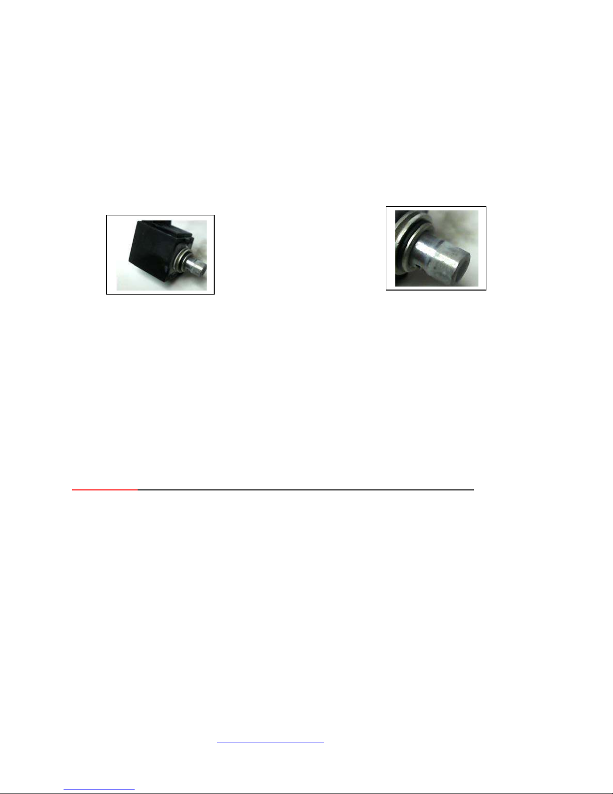
may start corroding in a very short amount of time (see photos below- after only thre e days submerged in t ap
water) leading to an eventual failure.
FlowTrax Fluid Path:
WARNING: Warranty does not include contamination of fluid path components caused
by use of test f luids other than di stilled water. A rep air of damage during th e warranty
period appearing to be the result of non-recommended test fluids being used will be
performed at a no minal flat rate. See Servi ces chart or contact P ronk Technologies for
details.
13) Routine Maintenance:
Glassware: Use only distil le d water with FlowTrax for proper ope ration, acc uracy and longevity o f the device.
Cleaning the glass tube is easy to do and is recommended at least once a month. An extensive design effort went
into making the Flo wTr ax glass tube assembly field removable to simplify glass cleaning/mainte nance. A tube
brush, clea ning soluti on (Wind ex® Origina l) and flush bottle have been provided for ease of maintenance. Use
only Windex ® Original for cleaning glas s tubes- other cleaners may contain chemicals that could cause damage
to FlowTrax.
IMPORTANT: Nev er remove Glass Tube Assembly before removing all water from FlowTrax.
Instructions for cleaning the removable Glass Tube Assembly:
a) Remove IV set from input to FlowTrax.
b) Power ON FlowTrax by pressing the green POWER button.
c) Remove side door exposing glass tube assembly.
d) Place FlowTrax Output hose into collection container.
e) Pr ess the F UNCTI ON but ton on F l owTrax. Press “CLEAN GL ASS” b utton. The CLE AN GL ASS funct ion
will automatically expel all visible water out of FlowTrax glass tube assembly. It will also position the
optical carriage in the center of the tubes, thus avoiding any interference when removing.
f) Remove Glass Tube Assembly by pulling outward from the top of the assembly, then pulling upward to
completely remove.
g) Using the tube brush pro vided, soak brus h in the clean ing soluti on pro vided. Insert br ush inside of the glass
tube while t wisting, pushi ng and pulling t hrough the t ube section. Co ntinue for ab out five second s in each
tube section.
h) Using distilled water and flus h bottle provided thoroughly fl ush cleanin g fluid out o f Glass Tube Assembly.
Dry off outside of glass tubes with a paper towel before re-installing into FlowTrax.
i) Re-insert Glass Tube Assembly (bottom end first). E ns ure positive fit into FlowTrax.
j) Re-prime FlowTrax and it is ready to be used.
Pronk Technologies
©2015
Page 12
2017 07-18
www.pronktech.com 800-541-9802
Page 12
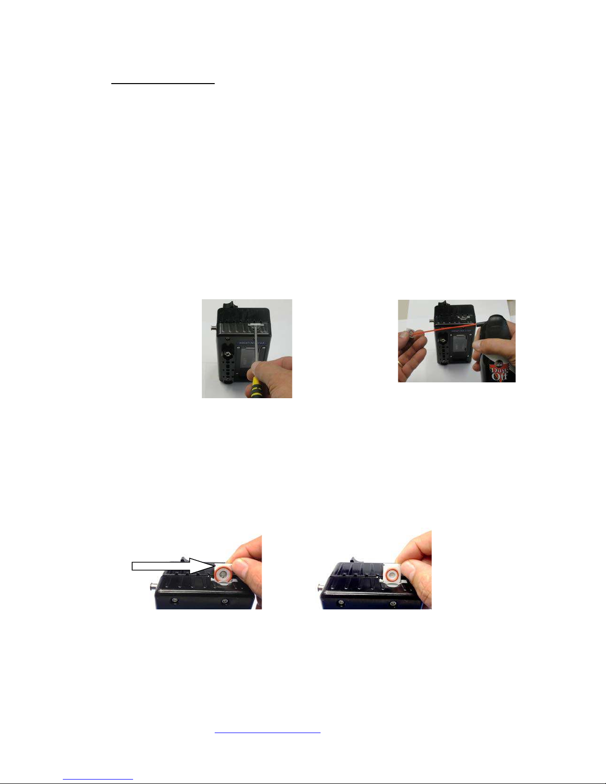
Filter: Use only distilled water with FlowTrax for proper operation, accuracy and longevity of the device.
(Figure 1)
(Figure 2)
CORRECT Method to Install Filter
INCORRECT Method to Install Filter
Large Red O-Ring
Warning: This will
cause Leaks. Small
NOT face toward
rear cover
Cleaning the filter is easy to do and is recommended at least once every 90 days. An extensive design effort went
into making the FlowTrax filter assembly field removable to simplify cleaning / maintenance.
Units configured wit h R emovable Input Luer:
a) Turn input luer counterclockwise to remove it from the unit.
b) Inside the threaded side of the Input l uer there is a white filt er screen. Usi ng a blunt too l, insert into the i nput
luer to remove filter.
c) Hold up screen up to indoor lighting to inspect for debris. Using brush provided, clean filter then rinse with
distilled water. If debris cannot be removed, replace with spare filter included with accessories.
d) Insert filter into threaded side of input luer using blunt too l. Verify filter completely co ve rs op enin g o f inp ut
luer, if not, remove and reinstall. IM PO RTA NT: Verify input luer is tightened so red dot on Luer is set to 12
o’clock position to ensure a secure fit and avoid leaks.
Units configured with Filter Drawer at bottom of Unit:
a) Place FlowTrax output hose in to collection container.
b) Expel all water from FlowT rax by pressing the “FUNCTION” button on FlowT rax, then Press “CLEAN
GLASS” button.
c) Place FlowTrax horizontally on its back.
d) Remove filter drawer assembly located at the bottom of the surface (See Figure 1) of FlowT rax with a small
flathead screw driver.
e) Inspect filte r element for contamination and or corrosion.
f) Contaminants can be blown out of the filter ele ment by using compr essed gas such a s Dust-Off
flushed over sink using a faucet. (See Figure 2)
g) Once contaminants and/or corrosion is removed,
distilled water to lubricate.
drawer assembly, before re-installing. If installed backwards, FlowTrax will leak and cause errors in
flow/volu me me as ur e me nts.
should face toward
rear cover of
FlowTrax
Clean the Product (Outside)
To clean the outside of the FlowTrax, disconnect from the power supply and use only a damp cloth with
mild detergent.
®
, or back-
wet both sid es of the filter drawer including the O-rings with
Re-install filter drawer assembly. NOTE: Ensure correct orie ntatio n o f filter
O-Ring should
Pronk Technologies
©2015
Page 13
2017 07-18
www.pronktech.com 800-541-9802
Page 13
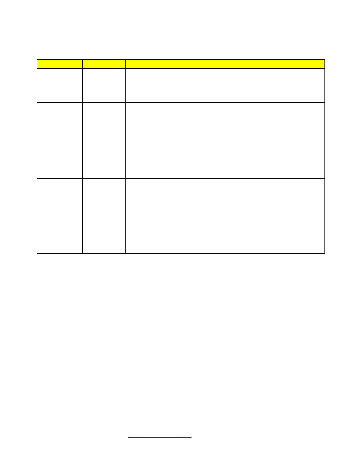
Segment
Frequency
Description
Monthly
low rates)
Consists of Glass Tube Assembly found by removing side door of
described in Routine Maintenance section of this manual.
Remove filter assembly and follow cleaning process described in
Consists of the manifold, occlusion chamber, O rings, transducer,
basis, performed as part of the systemic calibration test.
Consists of stepper motor, optics carriage, belt and pulleys.
systemic calibration test.
Calibration and maintenance of the entire FlowTrax system is
the device meets all specifications.
Preventative and Routine Maintenance Chart:
Glassware
Filter
Assembly
(weekly if
testing very
Quarterly
Fluid Path Annual
Mechanical Annual
System Annual
FlowTrax. Be sure to use “Clean Glass” function prior to removing
Glass Tube Assembly. Remove glass and follow cleaning process
Routine Maintenance section of this manual.
check valve, interconnect hosing, filter assembly, valves and valve
block. Glass Tube Assembly and Filter Assembly called out
separately. Maintenance of the Fluid Path and associated
components of the FlowTrax system is recommended on an annual
Maintenance of the entire mechanical parts of the FlowTrax system
is recommended on an annual basis, performed as part of the
recommended on an annual basis. The Pronk FlowTrax calibration
procedure must be followed by an authorized calibration company
using NIST traceable fixtures defined in the procedure to guarantee
Pronk Technologies
©2015
Page 14
2017 07-18
www.pronktech.com 800-541-9802
Page 14
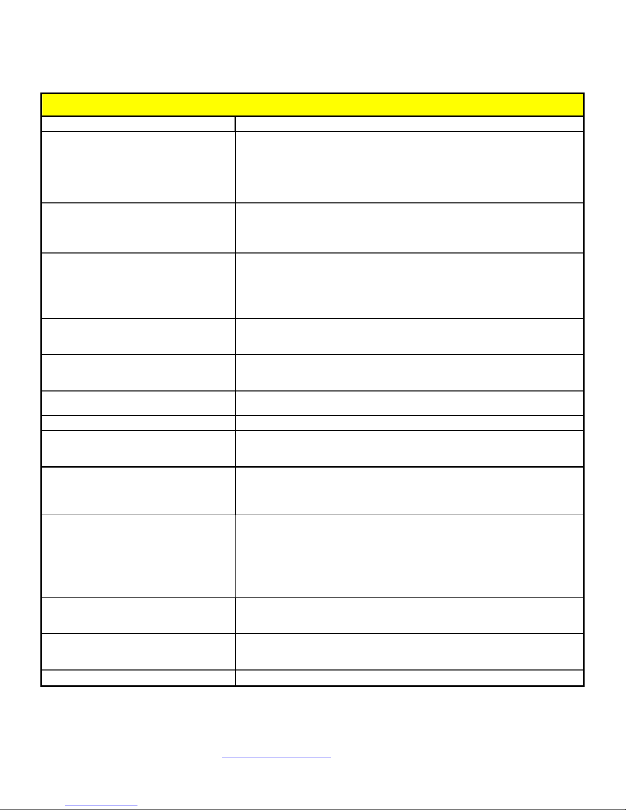
14) Flow Trax Troubleshooting Tips:
SW version 1.6 or higher TROUBLESHOOTING TIPS
SYMPTOM
SOLUTION
FlowTrax has deter mined the bubble in the glass tube assembly is not adequate
away.
FlowTrax will generate a “tracking” bubble once it determines that the glass tubes
Glass cleaning may be necessary. Remove IV set from input. Press FUNCTION
on its back (horizontal) for optimal performance.
Make sure to press the RESET FLOW button just be fore starting the pump. This
Ensure Occlusion knob is completely open counterclockwise.
Make sure occlusion knob on the FlowTrax is turned completely counter
and inspect for particles and or contamination. Clean filter assembly and reinstall.
Make sure to ZERO the pressure on the FlowTrax to atmosphere and then press
RESET FLOW before running an occlusion test.
Can’t zero STOPWATCH timer
Press and hold Stopwatch button for 2 seconds to return the timer to zero.
Some pumps have very inconsistent flow patterns. Use the volume divided by
Press SETUP, MORE, READINGS, select VOL/TIME.
If the “TILT” message won’t clear, and you are confident that the FlowTrax is on
with.
It’s possible for a small bubble to stick against the glass tube which must be
bottle provided. Re-install glass tube.
Make sure that the TWedge program is active / launched, the com port selection
and connected with adapter cables to your PC.
DataSnap: screen gets very strange when I
using with D ataSnap
This can happen if “Stream Data” mode is on, and you move away from the target
leaving a file / form / record that you were using to collect streaming data.
Unable to resolve
Contact Pronk Technologies Technical Support at: (800-541-9802)
for accurately measuring flow/volume. Press FUNCTION, then press FLUSH.
“Prime Required” message intermittently
appears
Program IV pump for 900ml/hr, 10ml volume. Start IV pump. When complete,
program IV pump for 600ml/hr, 20ml volume. While running this rate, press
EXIT on FlowTrax. Continue this rate until “Prime Required” message goes
Can’t remove or expel all bubbles from
FlowTrax
Volume number stopped during test, or
came out much lower than expected
Volume measurement is higher or lower
than expected
Keep getting occlusion alarm on infusion
device
Occlusion pressure doesn’t seem accurate
Flow Rate does not seem accurate
TILT message won’t clear or flashes on and
off
are full of water and no other unwanted bubbles are present. This bubble is
necessary to measure Flow and Volume. Do not try to remove or expel this
“tracking bubble.
button, the n press CLEAN GLASS button. Remo ve glass tube. Clean gla s s tubes
with bottle brush and cleaning solutio n provided. Fl ush out clea ning solution
from glass with flush bottle provid e d. Re-install glass tube. If running a low rate
test (1-20ml/hr), place FlowTrax
will ensure accurate results.
clockwise to allow fluid flow. If occlusion alarm persists, remove filter assembly
time (V/T) for accurate flow rates with infusion devices with very long pauses.
a very level surface, press SETUP, MORE, CHK TILT. Press ZERO in the upper
right corner to calibrate the accelerometer to the level surface you are working
removed.
Glass Tube Sensor Carriage does not move
when priming or attempting to take a
measurement
DataSnap: Won’t capture data or control
FlowTrax
exit or minimize the file/form/r e c ord I was
Pronk Technologies
Press FUNCTION, then CLEAN GLASS to remove water and small air bubble,
and then re-prime. If problem p ersists, Press FUNCTION butto n, then press
CLEAN GLASS button. Remove glass tube. Clean glass tubes with bottle brush
and cleaning solution provided. Flush out cleaning solut i on from glass with flus h
in TWedge, Configure, Interface is correct for your PC and that FlowTrax is on
file / record with your cursor. Make sure you select F8 (Stream Data OFF) before
©2015
Page 15
Pronk Technologies
2017 07-18
www.pronktech.com 800-541-9802
Page 15
©2015
Page 16
2017 07-18
www.pronktech.com 800-541-9802
Page 16
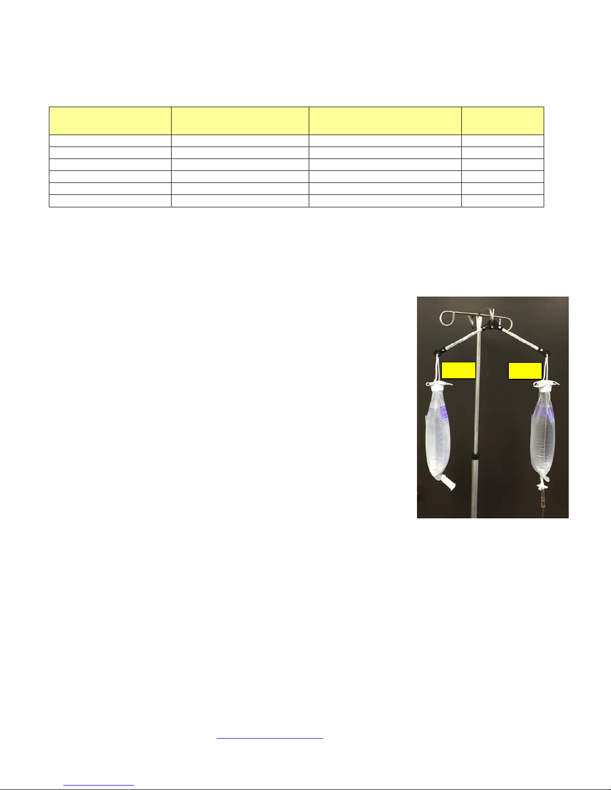
15) IV Pump Manufacturer height requirements chart:
Pump
Manuf/Model
Height Requirements
From
Tolerance
CareFusion 8100
19 to 21 Inches
Top of Water to Top of Pump
+/- 1 Inch
B-Braun Outlook
10 to 14 Inches
Top of Water to inlet of pump
+/- 2 Inches
B-Braun Space
50 cm (19.68 Inches)
Top of Water to middle of pump
NA
Hospira Plum XL
18 to 24 Inches
IV bag to cassette chamber
+/- 3 Inches
Hospira Plum A+
46-61 cm (18-24 Inches)
IV bag to pump chamber
+/- 3 Inches
Baxter Spectrum
24 Inches
IV bag to pumping mechanism
NA
Ballast
IV Bag
NOTE: These height requirements are for reference only, and are subject to change by each manufacturer.
16) HydroBalance™ Setup and Use
Description: HydroBalance ensures the IV source bag used for testing infusion pumps will be maintained at a
constant head height even as that source bag begins to drain during use. It utilizes a patent pend ing swivel arm
design that automatically adjust s the height of the IV source bag.
Setup:
NOTE: (2ea.) Kendall™ (Covidian™) 1000ml Gravity Feeding Bag,
Kendall Part # 702505 is required. Remove fluid tubing right at the top of
drip chamber. Utilize roller clamp to seal both bags. One bag will be used as
ballast, the other as the primary IV bag.
a) Attach the HydroBalance (HB-1) center loop to the IV pole.
b) Attach Primary IV bag to one arm of HB-1. Attach the “ballast” bag to the
opposite arm.
c) Ensure roller clamp on balla st bag is completely closed around end of tube
to avoid leaks. Fill the ballast bag with 1200ml of distilled water.
d) Remove roller clamp from end of primary IV bag. Spike IV set into the
tubing at the end of the bag. Ensure there is a tight seal. Clamp off IV set
to avoid leaks.
e) Fill the primary IV bag to the same level as ballast bag.
f) Ensure the IV set is not interfering wi th the balanc e of the two bags.
Adjust the water level in the ballast bag as needed so that both HB-1 arms
are level. Start Testing.
17) DataSnap Electronic Data Transfer and Control
Description: DataSnap provides real time results capture from FlowTrax® to any file, form or record open on your
PC. DataSnap also provides for control of your FlowTrax from your PC, including clearing prior test results for
subsequent testing and “Flushing” FlowTrax for priming. Using your keyboard function keys, users can transfer
FlowTrax test results or request FlowTrax send real time data for rate and volume every 10 seconds for graphing
Infusion pump performance over extended periods of time. In either case, the data will go directly into a file, form or
record you have open on your pc where you have selected a cell or box that results are normally typed into (including
notes fields in forms).
Pronk Technologies
©2015
Page 17
2017 07-18
www.pronktech.com 800-541-9802
Page 17
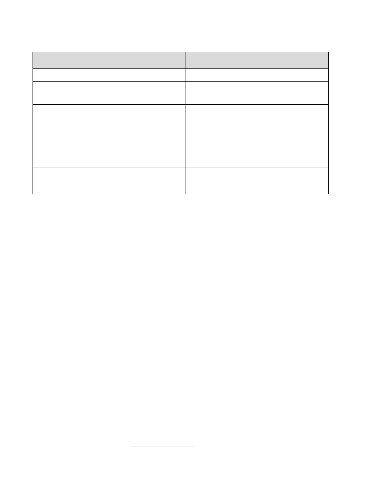
DataSnap Function Keys
For Laptops use FN key + desired function key to select
Description
Request Real time data for rate and volume at 10 second
F2-Help Legend for all DataSnap Hot Keys
F3-Reset Flow
(Alt-Z)
F4-Insert Volume
(Alt-V)
F6-Insert Max. Pressure
(Alt-P)
F7-10s Stream Data ON
F8-10s Stream Data OFF Turn off real time data request
F9-Flush Flo wTrax
Clear prior T est Results on FlowTrax
Request Volume Results
Request Maximum Pressure (Occlusion Pressure)
intervals
Put FlowTrax into “Flush” mode for Priming.
FlowTrax Requirements: To connect FlowTrax to yo ur PC for DataSnap capabilities, you will need the following
items:
• (1) FlowTrax Stereo to USB cable, Part # 501-9918.
• Install software program TWedge version 3.1. Trial version available on FlowTrax User Guide DVD.
• Install DataSnap Script onto T Wedge program. Located on FlowTrax User Guide DVD.
• FlowTrax so ftware versi on 1.6 or higher. Units with software 1.2 or lower will require factory
upgrade.
PC Requirements for TWedge Software
Memory: At least 25 MB RAM per managed device (higher in case of complex data acquisition logic of customized
scripts).
Operating Systems: All current 32 and 64 bit Microsoft Windows systems:
• Windows Server 2003, 2008, 2008 R2, 2012, 2012 R2, Windows Vista, Windows 7 and Windows 8.
• For legacy systems like Windows XP or Windows XP based systems (e.g. Windows Embedded and
Windows Embedded POS Ready), TEC-IT provides support only on a voluntary basis (no legal
entitlements).
DataSnap Overview: The TWedge software translates serial data into keystrokes. The DataSnap Script defines the
commands of each Function key. A DataSnap script file is available from Pronk at no additional charge that can be
modified by the user if needed. FlowTrax software version 1.6 or higher is required and can be updated to this
version re motely witho ut send ing the Flo wTrax b ack to Pronk T echnol ogies. Units with software 1.2 or lo we r will
require a factory upgrade.
TWedge Software: The wedge program is called TWedge V3 and is provided by Tec-IT found on t he interne t at
(
http://www.tec-it.com/software/data-acquisition/twedge/keyboard-wedge/Default.aspx
program is available on the FlowTrax User Guide DVD provided with the FlowTrax and can be downloaded to your
PC. Once downloaded to your PC you can purchase a license through Tec-IT over the inte rnet.
DataSnap Script: The Script file defines the action of the Function keys and is also located on the FlowTrax User
Guide DVD provided. It was developed by Pronk Technologies as “shareware” and there is no implied or specific
warranty or support. It can be modified by users where more customization is needed.
). A demo version of this
Pronk Technologies
©2015
Page 18

2017 07-18
www.pronktech.com 800-541-9802
Page 18
Setup Instructions (only ne eded the first time yo u load/launch TWedge on a PC): Follow the steps below for
setting up D ataSnap on F lowTrax:
a) Load the DVD provided with your FlowTrax labeled FlowTrax User Guide into your PC DVD drive.
b) Once the DVD drive is available to see in Windows explorer or similar program, open folder labeled
“DataSnap Setup” and launch installer file “Twedge_Setup”. Double click file to launch installer.
c) Follow prompts until complete. (Check with your network administrator for install permissions)
d) Browse “DataSnap Setup Information” folder on DVD drive and copy file called “FT DataSnapScript_1-
0.twg.” onto your PC hard drive in a folder you will remember for later (i.e. create a folder
C:\TwedgeScript) and save it in that folder.
e) Double click TWedge Icon from desktop to start program.
f) When the file opens you will be prompted to either purchase a test license online or to select the
unlimited access for (10) days. If you select Yes, you will be taken to the TEC-IT website to purchase
the license. The license required to purchase is TWedge Single. It is located in the Data Acquisition
Tools section of the web site. No additional software is required to purchase.
g) Choose “File” in upper left corner.
h) Choose “Open”.
i) Browse your hard drive for the file called “FT DataSnapScript_1-0.twg”, located in the folder you
saved it into in the earlier step.
j) Double click / select that file. Once loaded, you will see the file name in the upper left hand side of the
TWedge screen.
k) If Plug and Play feature is enabled on your PC, connect Serial to USB cable provided with DataSnap
accessories to your PC. Driver will be downloaded automatically from a safe device driver website.
If Plug and Play not available, DO NOT connect Serial to USB cable. First load the Driver manually to
your PC by accessing the driver setup program called “CDM v2.12.06 WHQL Certified.exe” located on
the FlowTrax User DVD under folder DataSnap Setup Information. Once driver loaded, connect Serial
to USB cable to your PC.
l) Connect Stereo plug of the cable to top port on FlowTrax.
m) Identify what Com Port your PC has assigned to FlowTrax serial USB adapter connection using
Device Manager or similar program.
n) From TWedge program menu, go to “Device” then select “Configure”, select “Interface” and then
change Com Port setting to the Com port you identified earlier (i.e. Com 4).
IMPORTANT NOTE 1: When using the Stream Data feature of DataSnap, be aware that if you minimize the record
you are capturing data into you will have adverse effects because the data is now streaming across the USB port as
if you were typing keys on your keyboard. For example, if you minimized or closed Microsoft Excel while Stream
Data was still ON, some applications or programs may launch from your desktop because the data is translated into
key strokes. Ensure your cursor is flashing in the location you wish data to be transferred to.
IMPORTANT NOTE 2: Your PC assigns USB com ports based on their physical location on your PC. Ideally you
should always connect FlowTrax to the same physical USB port so that you don’t have to reconfigure the TWedge
program each time you reconnect your FlowTrax to your PC. One way to avoid this issue is to use a small label /
sticker “FT” directly above the physical USB connection on your PC so you don’t have to remember which one to
connect to.
IMPORTANT NOTE 3: Ensure stereo connection to FlowTrax is installed all the way into FlowTrax (d oor is not
interferin g) and that the Fl owTrax i s turned on and primed.
Running DataSnap: Collecting Data from FlowTrax:
a) From TWedge Program, Click on start symbol . (Or you can Click on Device, then click Start.)
b) Press F3 (FN+F3 for laptops) - this should Reset your FlowTrax, clearing all data displayed. This
confirms communications are functioning.
c) Minimize TWedge program.
d) Now that TWedge is running and configured for that USB port, you can open any file, form or record,
click on a text box /cell and use the Function keys to capture results from FlowTrax into that text box
or cell.
Pronk Technologies
©2015
Page 19
2017 07-18
www.pronktech.com 800-541-9802
Page 19
e) When closing the TWedge program for the first time, you will be prompted to save the changes you
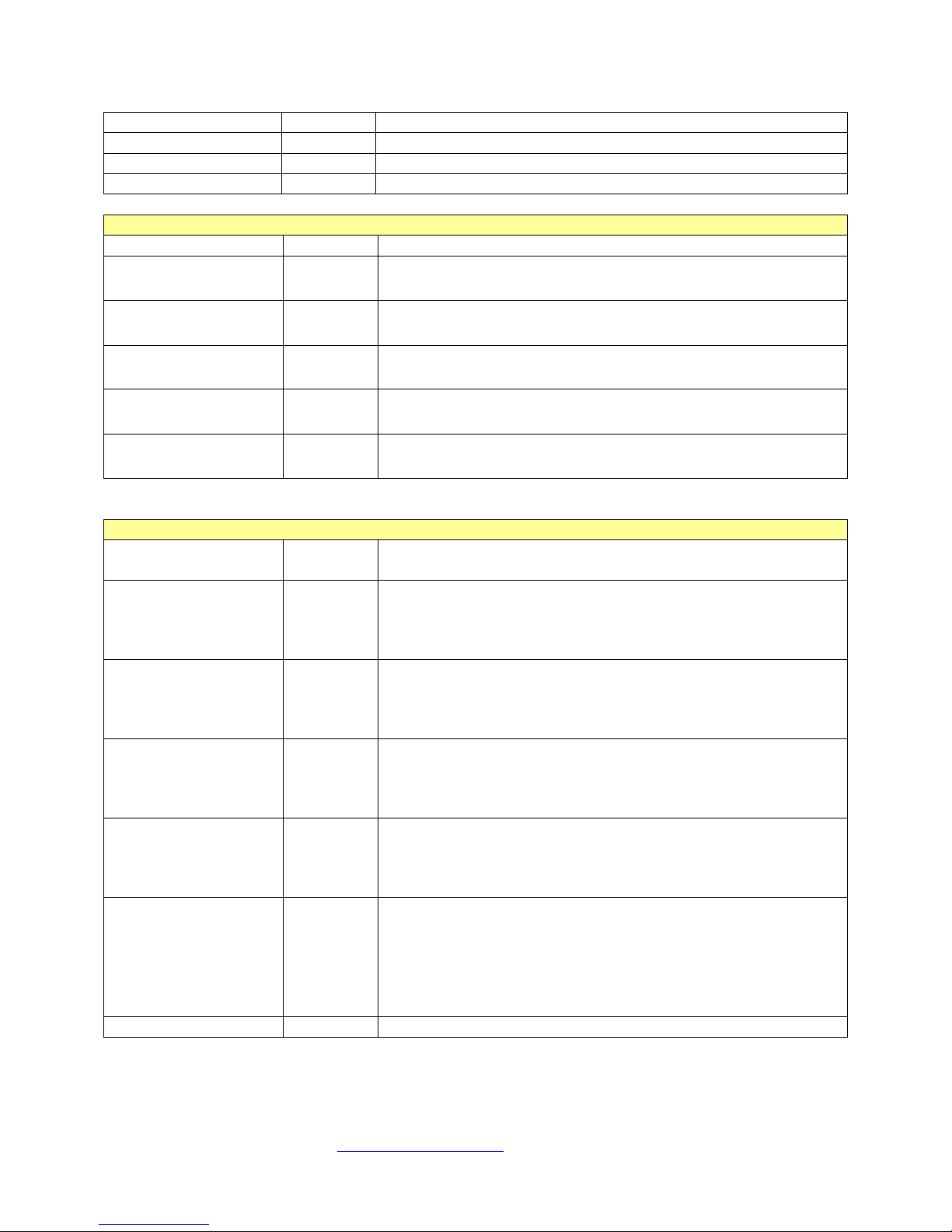
Commands and Reports for all Modes
Function
Command
Detailed Description
Reset Reading
Resets the bubble tracker and the flow m eter (volume, rate and
stopwatch, stops and clears the trend timer. 1.0 and above.
Device ID Report
1.4 and below: returns “FlowTrax”
future version: ‘FlowTrax SN XXX’
Poll Software V ers io n
‘V’
Returns software version, e.g.: “SW: 1.4.0C2”
Enter Flush Mode
‘F’
Enters flow thru mode. Use ‘R’ to exit.
Enter Clean Glass
Mode
Fills glass with air. Use ‘R’ to exit.
Zero Pressure
Command
Zeros pressure transducer offset and Max Press
Zero Max Pressure
‘z’
Zeros Maximum Pressure
Poll Tube Calibration
and settings
Returns tube cal, and settings: bubble size, front optical, rear
optical, e.g.: “C,1290,84,50,49”
made. This refers specifically to the com port assignment you changed. Click /select yes to save the
changes.
f) The next time you launch TWedge on that PC it will use the same script file with the correct com port
assignment without any further modifications. You will only need to click on START within TWedge
to begin communications with FlowTrax assuming it’s primed, connected and powered on.
NOTE: Ensure you Reset (F3) to clear prior data before data capturing.
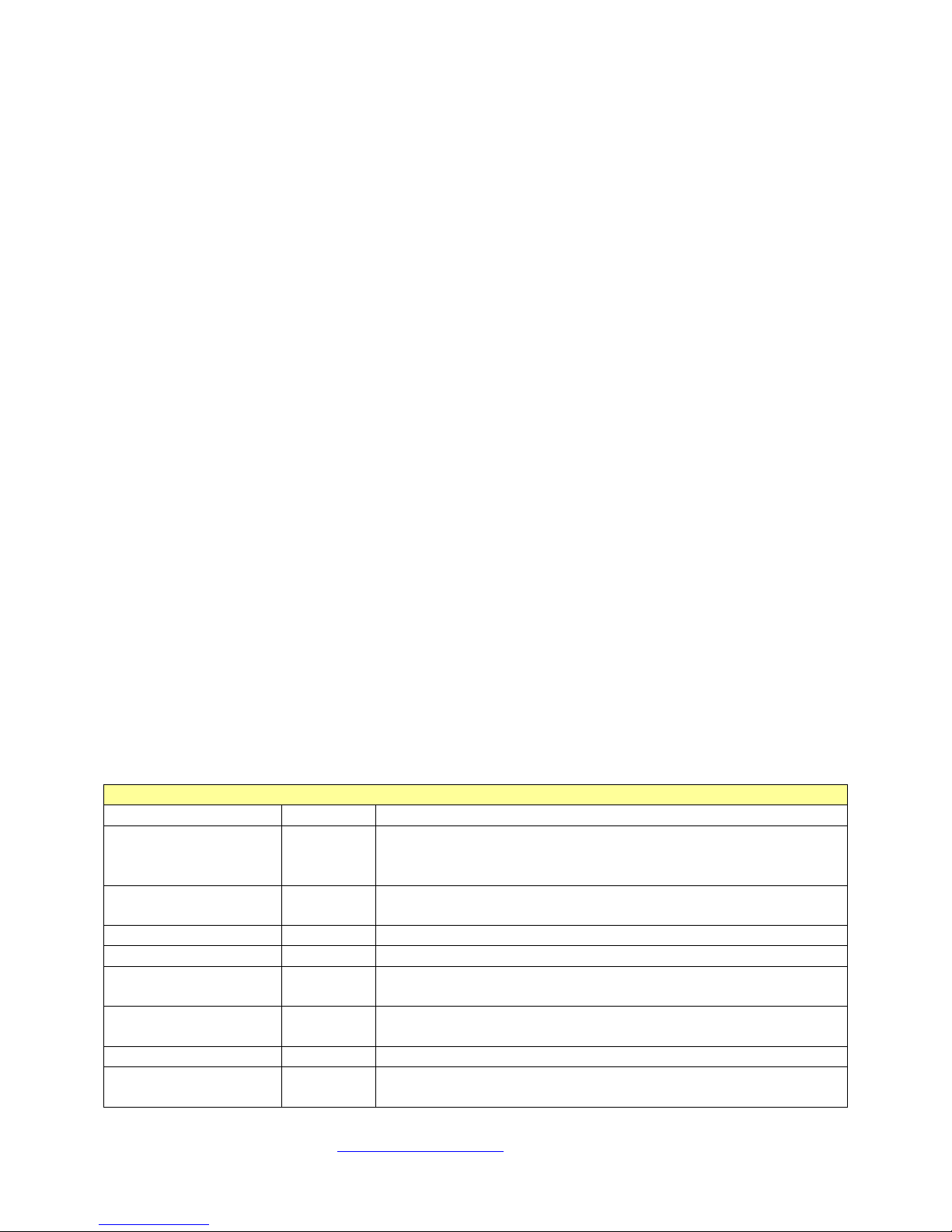
Flow Trax Serial Port Protocol
18)
Overview: The FlowTrax with software version 1.5 or hi gher comes standard with a serial (RS-232) communication
interface. This feature enables the FlowTrax to send results to a customer’ supplied interface as well as
commercially available programs like HyperTerminal. FlowTrax Serial Port can be easily adapted for computers
with USB ports by using a Serial to USB converter. Test results that can be cap tured fro m FlowTrax via the Serial
interface include Flow Rate, Volume, Pressure, Maximum Pressure, elapsed time and temperature. FlowTrax can
also be controlled by the customer’ supplied interface.
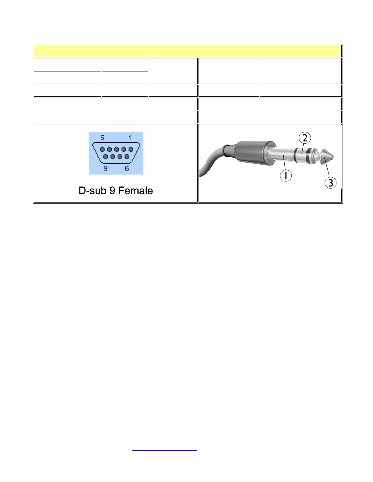
RS-232 Pin Assignments (chart/diagram at end of this section)
• DB-9 Female: Pin 2=Rx, Pin 3=Tx, Pin 5=Gnd.
• Stereo Jack: The Serial connector at 2.5mm Stereo Jack wired: Tip=Rx on DB-9, Base=Ground, Ring=Tx on
DB-9.
Configuring communications: Baud rate is 57600, 1 start, 1 stop, no parity, no handshake.
Important Notes before starting RS-232 communications:
1. All polls or commands going to the FlowTrax must have at least 2ms spacing between them as the
FlowTrax cannot receive back to back data at 57600 without losing data.
2. Use the Device ID report to verify the connection to the FlowTrax. (“I” upper case i)
3. Turn off Diagnostic mode when first est ablishing communic ations. (“g”, then “l” lower case L)
4. Prime status can be checked using serial, by polling the volume (“v”)
5. Run fluid into the FlowTrax until it primes. Then stop the flow and issue a Reset Reading command (“R”).
Recheck prime status after the Reset Reading is complete.
6. Use the Zero Pressure command to zero the pressure transducer. This should always be done with the inp ut
Lure fitting disconnected. (“Z”)
7. Pressure polling is available in PSI or mmHg. Pressure Curve data is always in PSI.
8. When connecting the stereo jack, Pressure units can sometimes change on the display.
9. Some FlowTrax keys may not function dur ing serial communications.
‘R’
rate history cleared), Resets the trend data, stops and clears the
‘I’
‘A’
‘Z’
‘C’
Pronk Technologies
©2015
Page 20
2017 07-18
www.pronktech.com 800-541-9802
Page 20
Zero Stopwatch Time
‘W’
Poll Stopwatch Time
‘w’
Returns the stopwatch time in seconds
Diagnostic Data On
‘G’
1.4 and above. Default is on
Diagnostic Data off
‘g’
1.4 and above
Polls and Replies for Data mode (SW 1.5 and higher)
Function
Poll
Reply
Poll Pressure in
‘p’
‘p,’yyyy,xxxx<cr><lf> Y is current pressure, X is max pressure ,
Poll Pressure in
‘m’
‘m,’yyyy,xxxx<cr><lf> Y is current pressure, X is max pressure ,
‘v’
‘v,’xxxx<cr><lf> X is volume in ul.
Poll Rate in 0.1
‘r’
‘r,’xxxx<cr><lf> X is rate on the screen in 0.1 ml/hr.
Poll YSI temp in
‘y’
‘y,’xxxx<cr><lf> X is YSI temp in 0.1C
Commands and reports for Trumpet mode (SW 1.5 and higher)
Function
Activated
By
Reports
reports “T,”XXX”V,YYY<cr><lf> where xxx is total reading
begins.
reports “T,”XXX”V,YYY<cr><lf> where xxx is total reading
begins.
reports “T,”XXX”V,YYY<cr><lf> where xxx is total reading
begins.
reports “T,”XXX”V,YYY<cr><lf> where xxx is total reading
begins.
Reports “T,” XXX “P,” YYY “X”,ZZZ<cr><lf> where xxx is
trumpet selection is made.
All curves off
‘q’
Turns pressure and trumpet curves off
PSI * 100
mmHg
Poll Volume in ul
ml/hr
0.1C
Turn on trumpet
curves at 10 sec
resolution
trumpet at 5 sec
‘h’
‘i’
positive or negative
positive or negative
Returns ‘NOT PRIMED’ or ‘NOT STARTED’ when appropriate.
Returns ‘NOT PRIMED’ when appropriate.
time in ms and yyy is total reading volume in ul. Trumpet curve
data does not start until the unit is primed, reset, and the flow
time in ms and yyy is total reading volume in ul. Trumpet curve
data does not start until the unit is primed, reset, and the flow
time in ms and yyy is total reading volume in ul. Trumpet curve
data does not start until the unit is primed, reset, and the flow
time in ms and yyy is total reading volume in ul. Trumpet curve
data does not start until the unit is primed, reset, and the flow
trumpet at 1 sec
trumpet at 200
ms
‘j’
‘k’
time since curve start in ms and yyy is current pressure, and zzz is
pressure curve at
‘n’
200ms
Pronk Technologies
the maximum pressure. Pressure and Max pressure are always
in 0.01PSI. Pressure curves begin immediately, regardless of
prime status and continues to run until “q” is sent or a different
©2015
Page 21
2017 07-18
www.pronktech.com 800-541-9802
Page 21
FlowTrax
Serial Communications: Pin outs and wiring chart
Abbreviation
Transmitted Data
Tx
3
Ring
Shown as 2
Received Data
Rx
2
TIP
Shown as 3
Common Ground
G
5
Base
Shown as 1
Signal
Name
19) Updating Software:
DB-9 Pin Stereo Jack Diagram ref.
NOTE: Loading a new software version into your FlowTrax can be done in the field with a PC
laptop, the USB cable provided and a file with the new version of software code. Update
FlowTrax software only in conjunction with a file provided by Pronk specifically for your
FlowTrax. Use of any other file may cause damage to the operation of your FlowTrax.
a) Connect the AC power adapter (provided) to your FlowTrax. Wait for full boot up to complete.
b) Press SETUP button, then USB button.
c) Next, press GO USB button. The FlowTrax screen will go dark.
d) Plug in USB cable provided to PC and to FlowTrax USB connector. (Rig ht side )
e) Yo ur PC will probably recognize that a new ‘drive’ has been connected and show you that the drive is
available. If not, navigate on the PC to look for the drive labeled “FlowTrax.”
f) On your PC, open the FlowTrax drive. You should see various file names on the dr ive, i ncl udin g the
current version of software. DO NOT REMOVE ANY FILES LOCATED IN THIS DRIVE.
g) On your P C, navigate to the file where the new versio n of Flo wTra x software is located. Drag and
drop the ne w file into the Flo wTr a x drive file / folder . Wait until the file has completely uplo aded.
This may take up to a minute.
h) Once the file has uploaded, you may get a message from your PC stating “USB drive not recognized”
or similar. Ignore this message.
i) Verify that the FlowT rax drive file / folder now includes the correct version name/number for the
software you just uploaded.
j) Disconnect USB cable at your FlowTrax.
k) Remove the AC power adapter from the Fl owTra x. Wait 10 seconds, then re-connect AC power
adapter. Wait for full boot up to complete.
l) Verify successful software upload by pressing SETUP button and confirming the correct version
number at the top of the Setup page.
m) Your new software has been completely uploaded.
Pronk Technologies
©2015
Page 22

2017 07-18
www.pronktech.com 800-541-9802
Page 22
Flow Trax Technical Specifications
Pressure Performance
Flow and Volume Performance
Flow Rate
Required Volume/Time
.5 to 10ml/hr
0.5ml
10.1 to 199ml/hr
3 minutes (see “Flow Rate and Volume Accuracy - Time vs. Volume”
Section in Op. Manual)
200 to 999ml/hr
10ml
Te mperature Performance
Digital T im er / Stop W atch
Accuracy: 0.5%
*Requirements for Flow Rate and Volume accuracy specification: Distilled water as test solution, output bottle height
Range: Manual: -12.5 to +75 PSI
Electronic Occlusion (IV pump Testing): 0 - 40 PSI
Accuracy: 0.5% of reading +/- 1 LSD
Resolution: .01 PSI
Units of Measure: mmHg, PSI (G), inH20, cmH2O, kPa, atm, inHg, BAR (A), BAR (G)
Range: 0.5 to 999 ml/hr
Accuracy*: 1% of reading ± 1 LSD for 1ml/hr to 999ml/hr, 2% ± 1 LSD below 1ml/hr. 0.85% of reading
for 500ml/hr, 12ml Volume under steady flow conditions.
Requirement for Accuracy:
Precision
Volume: ≤ 0.01ml
Precision of FlowTrax is equivalent to 0.01 g based on the conversion of volume (ml) to weight (g) by
calculation using standard temperature and density value of water. Precision was established using a rate
of 500ml/hr and a “dispensed” volume of 10ml.
Range: -28.9 to +115.5°C
Accuracy: 0.1% +/- 0.2 °C
Resolution: 0.1 °C
Range: 0 to 12 Hours
General
Power: Powered by two AA (Alkaline or Lithium) cells or 6 VDC Input
Battery life: Alkaline – minimum 4 hours, Lithium – minimum 12 hours
Size (HxWxD): 5.5 in (13.97 cm) x 3.25 in (8.26 cm) x 2 in (5.08 cm)
Environmental: Operating Temperature: 10 to 35 °C (50 to 95 °F)
Storage and Shipping Temperature: -10 to +40 °C (14 to 104 °F) with water drained.
Humidity: 10% to 80% non-condensing, Altitude: 0 to 6500 feet (2000 meters)
of 0 to 18” (45.7 cm) above FT output, FT horizontal for rates below 21ml/hr, vertical for rates at or above 21ml/hr.
Pronk Technologies
©2015
Page 23
2017 07-18
www.pronktech.com 800-541-9802
Page 23
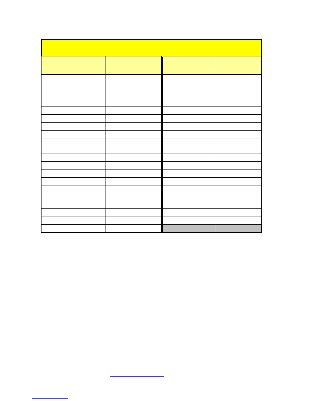
Flow Rate and Volume Accuracy- Time vs. Volume
Desired
(ml/hr)
Required VOLUME
Desired
(ml/hr)
Required
VOLUME
0.5 – 10
0.5
110
5.5
15
0.75
115
5.75
20
1
120 6 25
1.25
125
6.25
30
1.5
130
6.5
35
1.75
135
6.75
40
2
140
7
45
2.25
145
7.25
50
2.5
150
7.5
55
2.75
155
7.75
60
3
160
8
65
3.25
165
8.25
70
3.5
170
8.5
75
3.75
175
8.75
80
4
180 9 85
4.25
185
9.25
90
4.5
190
9.5
95
4.75
195
9.75
100
5
200 - 999
10
105
5.25
3 Minute Testing Quick Reference Chart
RATE
RATE
Pronk Technologies
©2015
Page 24

2017 07-18
www.pronktech.com 800-541-9802
Page 24
Flow Trax
The FlowTrax Infusion Device Analyzer is warranted against defects in materials and workmanship for a
period of four (4) years from the date of shipment to the original purchaser. Warranty is valid only to the
original buyer. Defective equipment should be returned freight prepaid to Pronk Technologies. Equipment
returned with defective parts and assemblies shall be either repaired or replaced at the manufacturer’s sole
discretion. This warranty is not applicable if the unit has been opened, if repair has been attempted, if the unit
has been damaged due to operation outside the environmental and power specifications for the product, if a test
fluid is used other than distilled water or due to improper handling or use, or if it has been calibrated by an
unauthorized calibration lab.
Warranty is for a period of one (1) year from date of shipment to the original purchaser, when original
purchaser is located outside North and South America. This warranty is extended to (2) years, if the product is
calibrated by Pronk or a Pronk authorized service center within 14 months of original shipment. All other
standards warranty terms apply.
If any fault develops, notify Pronk Technologies (see Returns and Repairs) giving full details of the difficulty,
and include the model and serial number of the device. Upon receipt of shipping instructions, forward the
device prepaid and repairs will be made at the factory.
If Pronk Technologies determines a fault has occurred as a result of test fluid being used that is not
recommended, that repair will be billable. A repair during the warranty period resulting from non- recommended
test fluids being used will be performed at a no minal flat rate. The warranty will be reinstated follo wing that
repair (i.e. if the repair occurs 3 years into the warranty, the warranty period will continue for one more year).
Limited Warranty
The forego ing warr anty is i n lieu o f all othe r warr anties e xpre ssed or i mplied, includi ng but no t limite d to an y
implied warranty or merchantability, fitness or adequacy for any particular purpose or use. Pronk Technolo gies
shall be liable only for repair or replacement of the FlowTrax Infusion Device Analyzer and optional features.
Pronk Technologies shall not be lia ble for any incidental or consequential damages.
Order Cancellation and Refund Policy
You may return your item within 14 days of deli very for a ful l refund. We are unable to exchange items
however, if you received a defective or incorrect item, we will be happy to make an exchange). Item(s)
returned for refund mus t be in its original condition, undamaged and with no missing parts, packed in i ts
original packaging, a nd include both the ori ginal receipt and an RMA number.
We will notify you via e-mail or fax of your refund once we have received and processed the returned item.
You can exp ect a ref und wi thi n 7 to 14 busine ss d a ys of our r ece iving your retur n i n the sa me fo r m of pa yment
originally used for pur chase.
Returns and Repairs
Please call Pronk Technologies’ Service Department at 800-541-9802 to obtain a Return Merchandise
Authorization (RMA) number and the shipping address. Returns should be packaged securely in the original
packaging materials. The RMA number should be clearly marked on the packaging. If the retur n is for a ne w
item and is a result of our error, we will make arrange ments for payment o f return shipping. Otherwise, ite ms
should be returned freight prepaid to Pronk Technologies.
DataSnap Warranty and Support:
TWedge software- from Tec-IT: Disclaimer
The actual version of this product (document) is available as is. TEC-IT declines all war ranties which go beyond
applicable rights. The licensee (or reader) bears all risks that might take place during the use of the system (the
documentation). TEC-IT and its contractual partners cannot be penalized for direct and indirect damages or losses
(this includes non-restrictive, damages through loss of revenues, constriction in the exercise of business, loss of
business information or any kind of commercial loss), which is caused by use or inability to use the product
Pronk Technologies
©2015
Page 25
2017 07-18
www.pronktech.com 800-541-9802
Page 25
(documentation), although the possibility of such damage was pointed out by TEC-IT. We (TEC-IT) reserve all
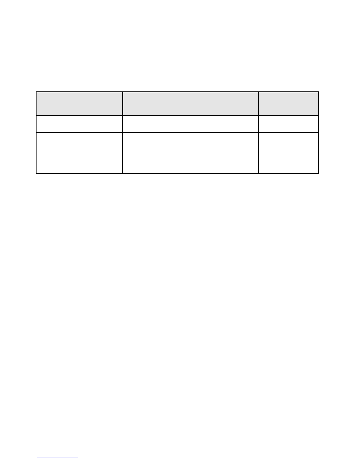
NUMBER
Annual FlowTrax Preventive
Maintenance Service
Full checkout, calibration and adjustment with
certificate.
Call For Pricing
Rejuvenation Service
May be required if FlowTrax is used with
other than
Inspect, clean and replace as needed:
valves,
(1) check valve.
Call For Pricing
rights to this document and the information contained therein. Reproduction, use or disclosure to third parties
without express autho rity is stri ctly forbidden.
Script File: It was developed by Pronk Technologies as “shareware” and there is no implied or specific
warranty or support. It can be modified by users where more customization is needed.
Services:
SERVICE ITEM
DESCRIPTION PRICE
Distilled or Deionized water.
(2) Fluid
(1) filter assembly, (1) transducer and
Pronk Technologies
©2015
 Loading...