


Draft 802.11n
Wireless Broadband Router
User’s Manual
February 2009
1

FCC Warning
This equipment has been tested and found to comply with the limits for a Class B digital device,
pursuant to part 15 of the FCC Rules. These limits are designed to provide reasonable
protection against harmful interference in a residential installation. This equipment generates,
uses, and can radiate radio frequency energy and, if not installed and u sed in a ccordan ce with
the instructions, may cause harmful interference to radio communication. Howe ver, there i s no
guarantee that interference will not occur in a particular installation. If this equipment does
cause harmful interference to radio or television reception, whi ch can be determined by turning
the equipment off and on, the user is encouraged to try to correct the interference by one or
more of the following measures:
- Reorient or relocate the receiving antenna.
- Increase the separation between the equipment and receiver.
- Connect the equipment into an outlet on a circuit different from that to which
- Consult the dealer or an experienced radio/TV technician for help. the receiver is
connected.
FCC Caution: Any changes or modifications not expressly approved by the party responsible
for compliance could void the user’s authority to operate this equipment.
This device complies with Part 15 of the FCC Rules. Operation is subject to the following two
conditions: (1) This device may not cause harmful interference, and (2) this device must
accept any interference received, including interference that may cause undesired operation.
IMPORTANT NOTE:
FCC Radiation Exposure Statement:
This equipment complies with FCC radiation exposure limits set forth for an uncontrolled
environment. This equipment should be installed and operated with a minimum distance of
about eight inches (20cm) between the radiator and your body.
This transmitter must not be co-located or operated in conjunction with any other antenna or
transmitter. IEEE802.11b or 802.11g operation of this product in the USA is
firmware-limited to channels 1 through 11.
Notice
Changes or modifications to the equipment, which are not approved by the party responsible for
compliance could affect the user's authority to operate the equ ipment. Company has an on-g oing policy
of upgrading its products and it may be possible that information in this document is not up-to-date.
Please check with your local distributors for the latest information.
REMARK
IEEE 802.11b or 802.11g operation of this product in the U.S.A. is firmware-limited to channels 1 through 11.
2

Copyright
2009 All Rights Reserved.
No part of this document can be copied or reproduced in any fo rm without written co nsent from
the company.
Trademarks:
All trade names and trademarks are the properties of their respective companies.
Revision History
Revision History
V1
1st
Release
3

Table of Contents
1. Introduction.................................................................................................................6
1.1 Features............................................................................................................ 6
1.2 Package Contents ........................................................................................... 7
1.3 LEDs Indication & Connectors of Wireless Router ...................................... 7
1.4 System Requirements..................................................................................... 8
1.5 Installation Instruction....................................................................................8
2. PC Configuration......................................................................................................... 8
2.1 TCP/IP Networking Setup................................................................................9
2.2 Setting up Internet Access ........................................................................... 18
2.3 Configure Wireless Station........................................................................... 19
3. Setup Wireless Router Configurations via Web Browser...................................... 20
3.1 Start your Web Browser................................................................................ 20
3.2 Setup Wizard.................................................................................................. 21
3.2.1 Gateway............................................................................................. 21
3.2.2 Bridge................................................................................................. 24
3.2.3 Wireless ISP ...................................................................................... 27
3.3 Operation Mode............................................................................................. 30
3.4 Wireless.......................................................................................................... 31
3.4.1 Basic Settings ................................................................................... 31
3.4.2 Advanced Settings............................................................................ 32
3.4.3 Security.............................................................................................. 32
3.4.4 Access Control.................................................................................. 33
3.4.5 WDS Settings .................................................................................... 33
3.4.6 Site Survey ........................................................................................ 34
3.4.7 WPS.................................................................................................... 34
3.5 TCP/IP Settings .............................................................................................. 37
3.5.1 LAN Interface..................................................................................... 37
3.5.2 WAN Interface ................................................................................... 38
3.6 Firewall...........................................................................................................39
3.6.1 Port Filtering...................................................................................... 39
3.6.2 IP Filtering ......................................................................................... 39
3.6.3 MAC Filtering..................................................................................... 40
3.6.4 Port Forwarding ................................................................................ 40
3.6.5 URL Filtering ..................................................................................... 41
3.6.6 DMZ.................................................................................................... 41
3.6.7 QoS..................................................................................................... 42
3.7 Management................................................................................................... 43
3.7.1 Status.................................................................................................43
4

3.7.2 Statistics............................................................................................44
3.7.3 DDNS.................................................................................................. 45
3.7.4 Time Zone Setting............................................................................. 45
3.7.5 Log ..................................................................................................... 46
3.7.6 Upgrade Firmware............................................................................. 46
3.7.7 Save/Reload Setting.......................................................................... 47
3.7.8 Password...........................................................................................47
3.8 Logout ............................................................................................................ 48
4. Troubleshooting........................................................................................................ 49
5
1. Introduction
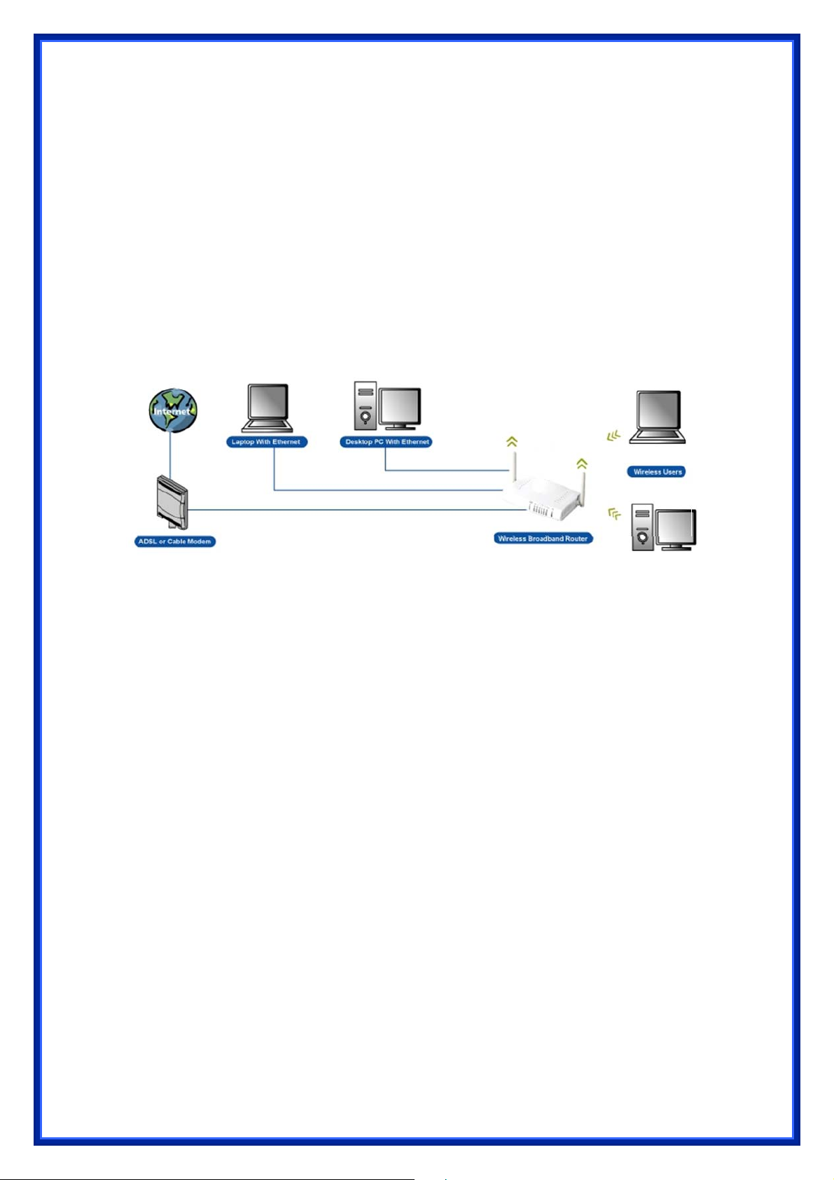
This Wireless Broadband Router is a draft 802.11n compliant device that provide faster and
farther range than 802.11g while backward compatible with 802.11g and 802.11b devices.
This Router uses advanced broadband router chipset and wireless LAN chipset solution let
you enjoy high-speed Wired and Wireless connection. Simply connect this device to a Cable or
DSL modem and then you can share your high-speed Internet access with multiple PCs at
your home. It creates a secure Wired and Wireless network for you to share photos, files,
video, music, printer and network storage. This device also supports the latest wireless
security features such as WEP, WPA, WPA2 and WPS to prevent from unauthorized access.
1.1 Features
Compliant with IEEE 802.11n draft 2.0 standard
Backward compatible with IEEE 802.11b/g
Supports NAT, NAPT, DHCP Server/Client
Supports VPN pass through - IPSec, PPTP, L2TP
Supports Virtual Server / Port Trigger / Port Forward
Supports Virtual DMZ Host, DNS Proxy, DDNS, UPnP
Supports 64/128-bit WEP Data Encryption
Supports WPA / WPA2 / WPS / 802.1x Authentication
Supports WDS (Wireless Distribution System) mode
Supports Quality of Service (QoS)
Supports MAC Filter, Client Filter, URL/IP Filter
Supports Hacker Pattern Detection
Supports Auto-crossover (MDI/MID-X) function
Supports software upgrade through Web
Friendly web-based GUI Configuration and Management
6
1.2 Package Contents
‧ One Wireless 11n AP Router
‧ One 12V DC Power Adapter
‧ One CD including user’s manual
‧ One RJ-45 Ethernet Cable
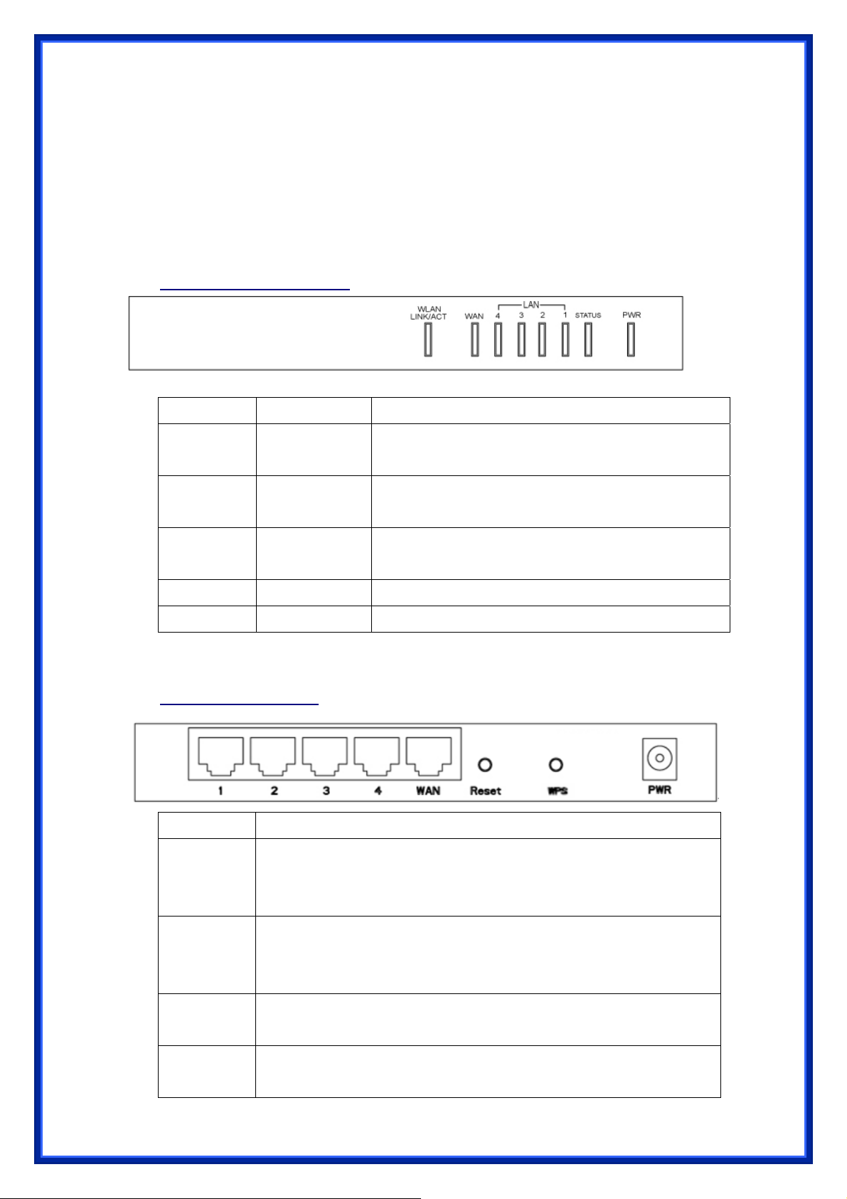
1.3 LEDs Indication & Connectors of Wireless Router
Front Panel LEDs Indication
LED Light Status Description
PWR On
Off
LAN
(1, 2, 3, 4)
WAN On
ACT (WLAN) Flashing Data is being sent or received.
LINK (WLAN) On
Back Panel Connectors
Button/Port Description
On
Flashing
Flashing
Wireless Router is powered on.
No power.
LAN port is successfully connected.
Data is being sent or received.
WAN port is successfully connected
Data is being sent or received.
Wireless connection is ready.
(1x, 2x, 3x, 4x)
Reset Reset configurations to default. You would use the reset button only when
a program error has caused your 11n AP router to hang. Press the button
and hold for 10 seconds.
WPS Click WPS button about 2-3 seconds while you are connecting a PC of
wireless adapter with WPS function (you must enable WPS’ PBC
function).
LAN
WAN Ethernet RJ-45 connector, connect to WAN access device, such as the
Ethernet RJ-45 connector, connect to PC with a RJ-45 Ethernet cable.
Cable modem or ADSL modem.
7

PWR Power connector, connect to the power adapter packaged with the AP
router.
1.4 System Requirements
‧ One or more PCs (desktop or notebook) with Ethernet interface.
‧ TCP/IP protocol must be installed on all PCs.
‧ Have valid Internet Access account and a DSL or cable modem.
‧ 10/100BaseT network cables with RJ-45 connectors.
‧ In case to use Wireless Access Point, all Wireless devices must be compliant with
IEEE 802.11b/g/n.
‧ System with MS Internet Explorer ver. 5.0 or later, or Netscape Navigator ver. 4.7 or
later.
1.5 Installation Instruction
1) Power off Wireless Router and DSL/cable modem.
2) Connect systems to the LAN ports on the Wireless Router with straight LAN cables.
3) Connect the DSL or cable modem to the WAN port on the Wireless Router.
4) Power on DSL or cable modem first, then connect power adapter to the power jack
on the Wireless Router and plug the power cable into an outlet.
5) Check LEDs.
a) Once power on Wireless Router, Power LED should be on.
b) LAN LED should be on for each active LAN connection.
c) The WAN LED should be on when the DSL or cable modem is connected.
Warning: Only use the power adapter is provided from this package, use other power adapter
may cause hardware damage
2. PC Configuration
User needs to configure TCP/IP network settings, Internet access configuration and
Wireless configuration for each system within Wireless Router’s LAN network.
By default, Wireless Router acts as a DHCP server for server version of Windows, it
automatically assigns IP address to each system when systems boot up. For all non-server
versions of Windows, the default TCP/IP setting acts as a DHCP client. If user chooses fixed
IP addresses for client systems, the Gateway of the client system must be set to the IP
address of the Wireless Router and DNS of the client system should be set to the address
provided by your ISP.
8
2.1 TCP/IP Networking Setup
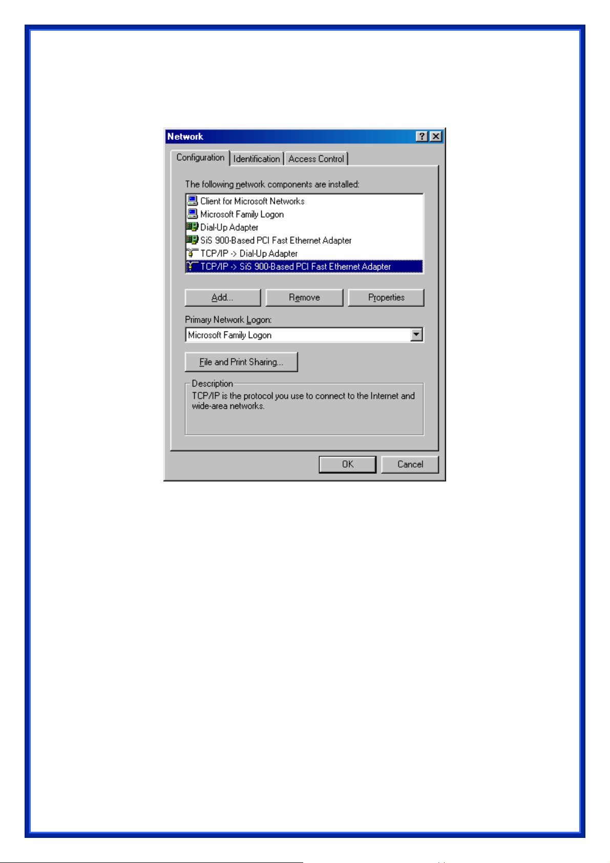
Checking TCP/IP Settings for Windows 9x/Me
a) Select “Start Æ Control Panel Æ Network”, the window below will appear:
b) Click “Properties”, the window below will appear:
9
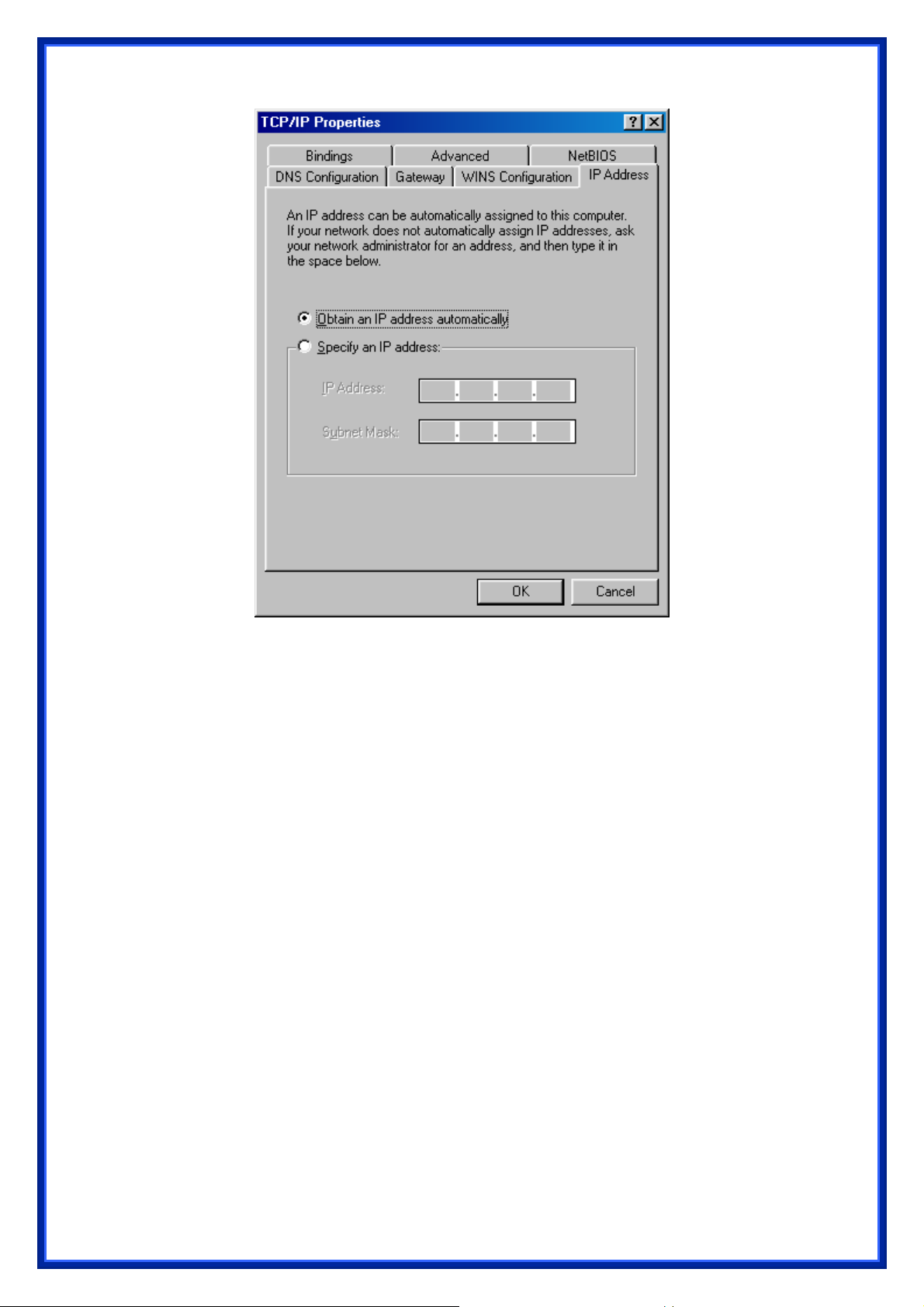
‧ If you decide to use DHCP, select “Obtain an IP address automatically”, then
click “OK” to confirm your settings. Once you restart your system, Wireless
Router will obtain an IP address for this system.
‧ If you decide to use fixed IP address for your system, select “Specify an IP
address”, and make sure that IP Address and Subnet Mask are correct.
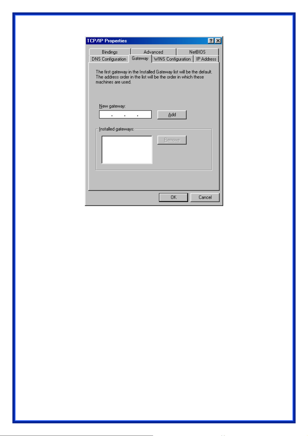
c) Select “Gateway” tab and enter correct gateway address in “New gateway” field,
then click “Add”:
10
d) Select “DNS Configuration” tab and make sure select “Enable DNS”, enter the DNS
address provides from your ISP in the “DNS Server Search Order” field, then click
“Add”:
11

Checking TCI/IP Setting for Windows NT4.0
a) Select “Control Panel Æ Network”, click “Protocols” tab then select “TCP/IP
protocol”, window shown as below will appear:
12
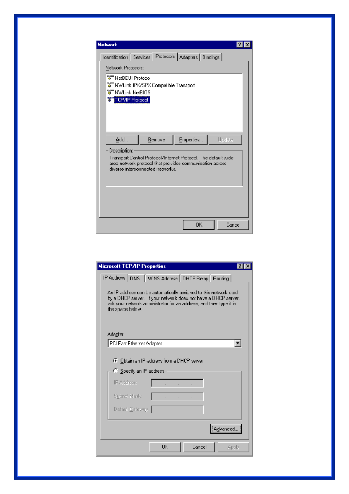
b) Click “Properties”, window shown as below will appear.
13
‧ Select the network card on your system from “Adapter” field.
‧ If you decide to use IP address from Wireless Router, select “Obtain an IP
address from a DHCP server”.
‧ If you decide to use the IP address you are desired, select “Specify an IP
address”. Make sure enter correct addresses in “IP Address” and “Subnet
Mask” fields.
‧ You must set Wireless Router’s IP address as “Default Gateway”.
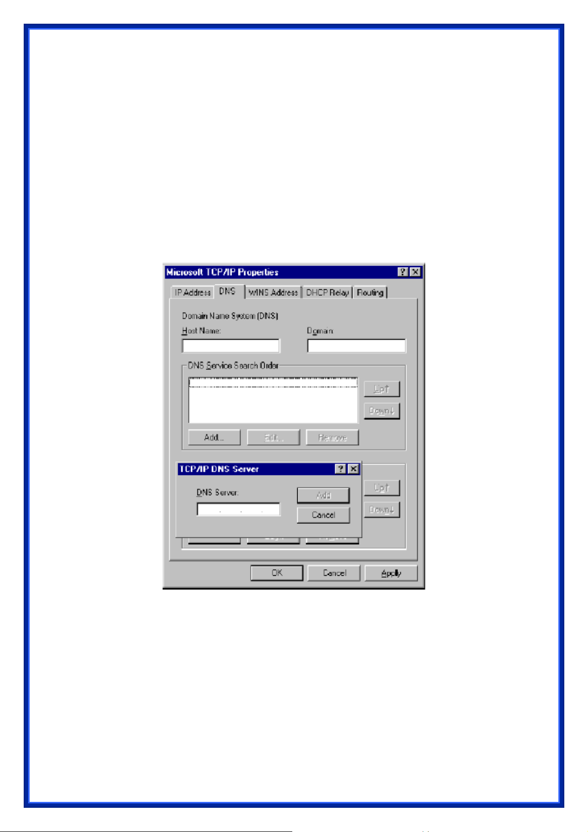
c) To enter DNS address is provided from your ISP. Select “DNS” tab, click “Add”
under “DNS Service Search Order” list, then enter DNS Server IP address in
“TCP/IP DNS Server” window and click “Add”.
Checking TCP/IP Settings for Windows 2000
a) Select “Start Æ Control Panel Æ Network and Dial-up Connection” and right click
“Local Area Connection” then click “Properties”:
14

b) Select the “Internet Protocol (TCP/IP)” for the network card on your system, then
click “Properties”, window shown as below will appear.
15

‧ If you decide to use IP address from Wireless Router, select “Obtain an IP
address automatically”.
‧ If you decide to use the IP address you are desired, select “Use the following
IP address”. Make sure enter correct addresses in “IP Address” and “Subnet
Mask” fields.
‧ You must set Wireless Router’s IP address as “Default Gateway”.
‧ If the DNS Server fields are empty, select “Use the following DNS server
addresses” and enter the DNS address is provided by your ISP, then click “OK”.
Checking TCP/IP Settings for Windows XP
a) Click “Start”, select “Control Panel Æ Network Connection” and right click “Local
Area Connection” then select “Properties”. The window shown as below
will appear.
b) Select “Internet Protocol (TCP/IP)” then click “Properties”, window shown as
below will appear.
16

‧ If you decide to use IP address from Wireless Router, select “Obtain an IP
address automatically”.
‧ If you decide to use the IP address you are desired, select “Use the following
IP address”. Make sure enter correct addresses in “IP Address” and “Subnet
Mask” fields.
‧ You must set Wireless Router’s IP address as “Default Gateway”.
‧ If the DNS Server fields are empty, select “Use the following DNS server
addresses” and enter the DNS address is provided by your ISP, then click “OK”.
17

2.2 Setting up Internet Access
This section describes how to setup Wireless Router Internet access through DSL or
cable modem.
For Windows OS
To access Internet via wireless router with Static IP method as example, the set up
procedures are showing below:
a) Access your ADSL Router Modem and configure the Internet setup (VPI, VCI, and
Encapsulation); and then, save the settings.
default internet setup already for the user).
(PS. Most of ISP companies will set the
b) Log in your wireless broadband router, Select “TCP/IP Setting” Section Î “WAN
Interface” Î Choose “Static IP”.
c) Enter “IP Address”, “Subnet Mask” and “Server IP Address”
d) In the below “DNS” option, select “Set DNS Manually” and enter the DNS Address
which is provided by your ISP; and then click “Apply Changes” button to save the
settings.
e) You can back to “Management” section Î “Status” to check the Internet status.
For Macintosh Clients
To access Internet via wireless router on Macintosh system, the set up procedures are
showing below:
a) Open the TCP/IP Control Panel.
b) Select Ethernet from the Connect via pop-up menu.
c) Select Using DHCP Server from the Configure pop-up menu. The DHCP Client ID
field can be left blank.
d) Close the TCP/IP panel and save your new settings.
If you decide to assign IP addresses manually instead of DHCP, set the Router
Address field with wireless router’s IP address and make sure DNS settings are
correct.
For Linux Clients
To access Internet via the wireless router, you need to set the wireless router as the
“Gateway”. Make sure login as “root” before attempting any changes.
Fixed IP Address
Most Linux installations use fixed IP address, if you wish to use a fixed IP address, make
sure make the following changes.
a) Set “Default Gateway” with the IP address of the wireless router.
b) Make sure DNS settings are correct.
To act as a DHCP Client (recommended)
18

The procedures below may vary depending on version of Linux and X-windows shell.
a) Start X-Windows.
b) Select Control Panel Æ Network.
c) Select the “Interface” entry for your Network card. Normally, this is called “eth0”.
d) Click “Edit” button, set the “protocol” to “DHCP” and save.
e) To apply all changes, use Deactivate and Activate buttons, if it is possible, restart
your system.
2.3 Configure Wireless Station
This section describes how to configure all the wireless stations use Wireless Router
as an Access Point. Each wireless station must have compatible settings as below.
Mode All wireless stations must be set to “Infrastructure” mode.
SSID
(ESSID)
WEP By default, WEP encryption is set to 64-bits 10 hex digit.
WPA By default, WPA-PSK Pass Phrase is set at PassPhrase, WPA G-Rekey
This code must match the value uses for the Wireless Router. (Note: SSID
code is case sensitive.)
Interval is set at 0 and WPA Data Encryption is at TKIP.
19

3. Setup Wireless Router Configurations via Web Browser
The Wireless Router comes with a web-based configuration utility. Users can access this
configuration utility from any of client system within Wireless Router’s LAN. For best results,
either use Microsoft Internet Explorer 5.0 or later, or Netscape Navigator 4.7 or later.
Before you start configuring your Wireless Router, you have to get following information from
your ISP:
a) Has your ISP assigned you a static IP address, or they will assign one to you
dynamically? If you have received a static IP address, what is it?
b) Does your ISP use PPPoE? If so, what is your PPPoE username and password?
If you are not sure of above questions, please contact your ISP.
3.1 Start your Web Browser
To use the Web-Based Utility, you have to launch your Internet Browser (MS IE 5.0 or
later, Netscape Navigator 4.7 or later).
Step1: Enter Wireless Router default IP address http://192.168.1.1
field then hit Enter key:
in the Address
Step2: Login dialog box will appear, enter admin as User Name and default
password is 1234, then click “OK” to login web-based utility.
20

3.2 Setup Wizard
This Setup Wizard will guide you to configure access for the first time. Please follow the setup
wizard step by step.
Depend on different modes, the setup wizard will be different. Please follow the below
brief descriptions:
3.2.1 Gateway
(1) Setup Operation Mode – Gateway: In this mode, the device is supposed to connect to
internet via ADSL/Cable Modem. The NAT is enabled and PCs in four LAN ports share the
same IP to ISP through WAN port. The connection type can be setup in WAN port. The
connection type can be setup in WAN page by using PPPoE, DHCP client, PPTP client, L2TP
client or static IP.
21

(2) Choose your Time Zone: You can maintain the system time by synchronizing with a
public server over the Internet.
(3) Setup LAN Interface: This page is used to configure the parameters for local area network
which connects to the LAN port of your AP Router. Here you may change the setting for IP
address, subnet mask, DHCP, etc.
22

(4) Setup WAN Interface: This page is used to configure the parameters for Internet network
which connects to the WAN port of your AP Router. Here you may change the access method
to static IP, DHCP, PPPoE, PPTP, or L2TP by click the item value of WAN Access type.
(5) Wireless LAN Setting: This page is used to configure the parameters for wireless LAN
clients who may connect to your AP Router.
23

(6) Wireless Security: This page allows you setup the wireless security. Turn on WEP or
WPA by using Encryption Keys could prevent any unauthorized access to your wireless
network.
3.2.2 Bridge
(1) Setup Operation Mode – Bridge: In this mode, all Ethernet ports and wireless interface
are bridged together and NAT function is disabled. All the WAN related function and firewall
are not supported.
24

(2) Choose your Time Zone: You can maintain the system time by synchronizing with a
public server over the Internet.
(3) Setup LAN Interface: This page is used to configure the parameters for local area network
which connects to the LAN port of your AP Router. Here you may change the setting for IP
address, subnet mask, DHCP, etc.
25

Attention: DHCP server of LAN will be disabled when you are using BRIDGE mode. Please
remember the IP address in this page and set up your computer with another fix IP in the same
domain to connect to this setup page in the future.
For Example: If the IP address of LAN is 192.168.1.1 and the Netmask is 255.255.255.0, you
can setup your computer with fixed IP 192.168.1.2 and Netmask as 255.255.255.0. After that,
you can type http://192.168.1.1
(4) Wireless Basic Settings: This page is used to configure the parameters for wireless LAN
clients who may connect to your AP Router.
in the web browser to connect this setup page.
26

(5) Wireless Security: This page allows you setup the wireless security. Turn on WEP or
WPA by using Encryption Keys could prevent any unauthorized access to your wireless
network.
3.2.3 Wireless ISP
(1) Setup Operation Mode – Wireless ISP: In this mode, all Ethernet ports are bridged
together and the wireless client will connect to ISP access point. The NAT is enabled and PCs
in Ethernet ports share the same IP to ISP through wireless LAN. You must set the wireless to
client mode first and connect to the ISP AP in Site-Survey page. The connection type can be
setup in WAN page by using PPPoE, DHCP client, PPTP client, L2TP client or static IP.
27

(2) Choose your Time Zone: You can maintain the system time by synchronizing with a
public server over the Internet.
(3) Setup LAN Interface: This page is used to configure the parameters for local area network
which connects to the LAN port of your AP Router. Here you may change the setting for IP
address, subnet mask, DHCP, etc.
(4) Setup WAN Interface: This page is used to configure the parameters for Internet network
which connects to the WAN port of your AP Router. Here you may change the access method
to static IP, DHCP, PPPoE, PPTP, or L2TP by click the item value of WAN Access type.
28

(5) Wireless LAN Setting: This page is used to configure the parameters for wireless LAN
clients who may connect to your AP Router.
(6) Wireless Security: This page allows you setup the wireless security. Turn on WEP or
WPA by using Encryption Keys could prevent any unauthorized access to your wireless
network.
29

3.3 Operation Mode
You can setup different modes to LAN and WLAN interface for NAT and bridging function.
Gateway: In this mode, the device is supposed to connect to internet via ADSL/Cable Modem.
The NAT is enabled and PCs in LAN ports share the same IP to S|ISP through WAN port. The
connection type can be setup in WAN page by using PPPoE, DHCP client, PPTP client, L2TP
client or static IP.
Bridge: In this mode, all Ethernet ports and wireless interface are bridged together and NAT
function is disabled. All the WAN related function and firewall are not supported.
Wireless ISP: In this more, all Ethernet ports are bridged together and the wireless client will
30

connect to ISP AP Router. The NAT is enabled and PCs in Ethernet ports share the same IP to
ISP through wireless LAN. You must set the wireless to client mode first and connect to the
ISP AP in Site-Survey page. The connection type can be setup in WAN page by using PPPoE,
DHCP client, L2TP client or static IP.
3.4 Wireless
3.4.1 Basic Settings
This page is used to configure the parameters for wireless LAN clients who may connect to
your AP Router. Here you may change wireless encryption settings as well as wireless
network parameters.
31

3.4.2 Advanced Settings
These settings are only for more technically advanced users who have a sufficient knowledge
about the wireless LAN. There settings should note be changed unless you know what effect
the changes will have on your AP Router.
3.4.3 Security
This page allows you setup the wireless security. Turn on WEP or WPA by using Encryption
Keys could prevent any unauthorized access to your wireless network.
32

3.4.4 Access Control
If you choose “Allowed Listed”, only those clients whose wireless MAC addresses are in the
access control list will be able to connect to your AP Router. When “Deny Listed” is selected,
these wireless clients on the lust will not be able to connect the AP Router.
3.4.5 WDS Settings
Wireless Distribution System uses wireless media to communicate with other APs, like the
Ethernet does. To do this, you must set these APs in the same channel and set MAC address
of other APs which you want to communicate with in the table and enable the WDS.
33

3.4.6 Site Survey
This page provides tool to scan the wireless network. If any AP Router or IBSS is found, you
could choose to connect it manually when client mode is enabled.
3.4.7 WPS
This page allows you to change the setting for WPS (Wi-Fi Protected Setup). Using this
feature could let your wireless client atomically synchronize its setting and connect to the
Access Point in a minute without any hassle.
Wi-Fi Protected Setup was designed to ease setup of security enabled WiFi networks in the
home and small office environment. It supports methods that are familiar to most consumers to
configure a network and enable security, like pushing a button (PBC method) or entering a PIN
34

code (PIN method). The new system, which will be incorporated in Windows Vista, will work
with computers, gateways peripherals, and consumer electronics.
You would initiate a WPS mode on gateway and then enter a simple sequence of digits (like a
PIN code) or press a button, use a similarly easy method to start a secure key exchange to
retrieve the WPA/WPA2 key.
This function allows you to change the setting for WPS (Wi-Fi Protected Setup). WPS can help
your wireless client earlier automatically connect to the Access Point.
AP Operation
In Realtek AP web server, you could find an WPS web page shown as the figure below:
(Figure 1)
To use WPS, you only need to click the button of “Start PBC”. Then click “OK”.
35

Windows Utility Operation (for RTL8192U Adapter)
Launch Realtek wireless client utility on Windows platform (2K or XP), you will see there is an
Wi-Fi Protect Setup tab existed, click the tab you will see a interface as shown in following
figure:
(Figure 2)
Push the “PBC(Push Button Config)” in this page, WPS feature will automatically setup the
setting.
(Figure 3)
36

After push “Push Button Config (PBC)” button, the program will automatically connect to the
AP router which has the feature of RTLTEK WPS. When connection is successful, you will see
the screen as below:
(Figure 4)
3.5 TCP/IP Settings
3.5.1 LAN Interface
This page is used to configure the parameters for local area network which connects to the
LAN port of your AP Router. Here you may change the setting for IP addresses, subnet mask,
DHCP…etc.
37

3.5.2 WAN Interface
This page is used to configure the parameters for Internet netwo rk which con nects to the WA N
port of your AP Router. Here you may change the Access Method to static IP, PPPoE, PPTP
or L2TP by click the item value of WAN Access Type.
38

3.6 Firewall
3.6.1 Port Filtering
Entries in this table are used to restrict certain types of data packets from your local net work t o
Internet through the Gateway. Use of such filter can be helpful securing or restricting your local
network.
3.6.2 IP Filtering
Entries in this table are used to restrict certain types of data packets from your local net work t o
Internet through the Gateway. Use of such filters can be helpful in securing or restricting your
local network.
39

3.6.3 MAC Filtering
Entries in this table are used to restrict certain types of data packets from your local net work t o
Internet through the Gateway. Use of such filters can be helpful in securing or restricting your
local network.
3.6.4 Port Forwarding
Entries in this table allow you to automatically redirect common network services to a specific
machine behind the NAT firewall. These settings are only necessary if you wish to host some
sort of server like a web server or mail server on the private local network behind your
Gateway’s NAT firewall.
40

3.6.5 URL Filtering
URL filter is used to deny LAN users from accessing the internet. Block those URLs which
contain keywords listed below.
3.6.6 DMZ
A Demilitarized Zone is used to provide Internet service without sacrificing unauthorized
access to its local private network. Typically, the DMZ host contains devices accessible to
Internet traffic, such as Web (HTTP) servers, FTP servers, SMTP(e-mail) servers and DNS
servers.
41

3.6.7 QoS
Use this section to configure Realtek's QoS. The QoS settings improve your online gaming
experience by ensuring that your game traffic is prioritized over other network traffic, such as
FTP or Web.
42

How to setup your QoS:
1. In QoS Setup Section, Enable QoS feature.
2. Choose Uplink Speed: “Automatic” or “Manual”
3. Configure QoS Rules – Name, Priority (1~255, 1 is highest), Protocol, Local IP range,
Local Port Range, Remote IP Range, and Remote Port Range.
4. Click “Save Settings” to save QoS configurations.
3.7 Management
3.7.1 Status
This page shows the current status and some basic settings of the device, such as System
information, Wireless Configuration, TCP/IP Configuration, and WAN Configuration.
43

3.7.2 Statistics
This page shows the packet counters for transmission and recepti on re ga rding to wirel ess a nd
Ethernet networks.
44

3.7.3 DDNS
Dynamic DNS is a service that provides you with a valid, unchanging, internet domain name
(an URL) to go with that (possibly ever-changing) IP address.
3.7.4 Time Zone Setting
You can maintain the system time by synchronizing with a public time server over the Internet.
45

3.7.5 Log
This page can be used to set remote log server and show the system log.
3.7.6 Upgrade Firmware
This page allows you upgrade the AP Router firmware to new version. Please note DO NOT
power off the device during the upload because it may crash the system.
46

3.7.7 Save/Reload Setting
This page allows you save current settings to a file or reload the settings from the file which
was saved previously. Besides, you could reset the current configuration to factory default.
3.7.8 Password
This page is used to set the account to access the web server of AP Router. Empty user name
and password will disable the protection.
47

3.8 Logout
This page is used to logout WLAN AP Webserver.
Click “Apply Change” button to logout the webserver. And then, you will see the below
screen:
48

4. Troubleshooting
This chapter covers some common problems that user may encoun ter while a ccessing the
wireless router and some possible solutions for them. If you follow the suggested
instructions to configure the wireless router, but router still does not function properly,
please contact your local dealer for assistance.
Q1) Can not connect to the wireless router.
Ans: Check the following.
a) If the wireless router is properly installed, if LAN connections are OK, and if
wireless Router is powered on.
b) Ensure that your PC and wireless router are on the same network segment.
c) If your PC is set to “Obtain an IP Address automatically” (DHCP client), restart it.
d) If your PC uses a Fixed (Static) IP address, ensure that it is using an IP Address
within the range 192.168.1.2 to 192.168.1.254 and thus compatible with the
wireless router’s default IP Address of 192.168.1.1. Also, the Network Mask
should be set to 255.255.255.0 to match the wireless router. In Windows, you
can check these settings by using “Control Panel Æ Network” to check the
“Properties” for the TCP/IP protocol.
Q2) When I enter a URL or IP address I get a timed out error.
Ans: A number of things could be causing this. Try the following troubleshooting steps.
a) Check if other PCs work. If they do, ensure that your PCs IP settings are
correct. If using a fixed (static) IP address, check the Network Mask, Default
gateway, and DNS as well as the IP Address.
b) If the PCs are configured correctly, but still not working, check the wireless
router. Ensure that it is connected and on. Connect to it and check its settings. If
you can’t connect to it, check the LAN and power connections.
c) If the wireless router is configured correctly, check your Internet connection
(DSL/cable modem etc) to see that it is working correctly.
Q3) Some applications do not run properly when using the wireless router.
Ans: The wireless router processes the data passing through it, so it is not transparent.
Use the Special Applications feature to allow the use of Internet applications that do
not function correctly. For example, you can use DMZ function, this should work with
almost every application but there is a security risk since firewall is disabled and only
one PC can be used in this feature.
49

Q4) My PC can not locate the wireless router.
Ans: Check the following.
a) If your PC is set to Infrastructure Mode, because the router is always in
Infrastructure Mode.
b) If the SSID on your PC and wireless router are the same. Remember that the
SSID is case-sensitive.
c) If both of your PC and wireless router have the same WEP settings. The default
setting for the wireless router is disabled, so your wireless station should also
have WEP disabled.
d) If WEP is enabled on the wireless router, your PC must have WEP enabled, and
the key tables (64/128 bit encryption) must match.
e) If the wireless router’s wireless screen is set to allow LAN access to select
wireless stations only, then each of your wireless stations must have been
selected or access will be blocked.
f) To see if radio interference is causing a problem, check if connection is possible
when close to the wireless router. Remember that the transmission range can
be as short as 100 feet in poor environment.
Q5) Wireless connection speed is very slow.
Ans: A wireless system transmission speed depends on the distance and the environment.
To obtain the highest possible connection speed, you can try the followings:
a) Try to adjust wireless router location and orientation.
b) If there are interference problems, change to another wireless channel.
c) If other devices cause the interference, you should turn off that device or
relocate it.
Q6) The “Status” light is ON (steady Green) after power on, it means the router is hun g
Ans : Please disconnect the power adapter from the power jack on the router and reconnect
the power adapter again to the router, check if the “Status” light is flashing normally.
50
 Loading...