


PRONAR Sp. z o.o.
17-210 NAREW, UL. MICKIEWICZA 101A, PODLASKIE PROVINCE
phone: +48 085 681 63 29 +48 085 681 64 29
+48 085 681 63 81 +48 085 681 63 82
fax: +48 085 681 63 83 +48 085 682 71 10
www.pronar.pl
OPERATOR'S MANUAL
AGRICULTURAL TRAILER
PRONAR T669XL
PRONAR T700XL
TRANSLATION OF THE ORIGINAL COPY OF THE MANUAL
ISSUE 2A-09-2016 PUBLICATION NO 538N-00000000-UM


INTRODUCTION
Information contained herein is current at date of publication. As a result of improvements,
some numerical values and illustrations contained in this publication may not correspond to the
factual specification of the machine supplied to the user. The manufacturer reserves the right to
introduce design changes in machines produced that facilitate operation and improve the quality
of their work, without making minor amendments to this Operator's Manual.
This Operator's Manual is an integral part of the machine's documentation. Before using the
machine, the user must carefully read this Operator's Manual and observe all
recommendations. This guarantees safe operation and ensures malfunction free work of the
machine. The machine is designed to meet obligatory standards, documents and legal
regulations currently in force.
The manual describes the basic safety rules and operation of agricultural trailer Pronar T700XL,
Pronar T669XL.
If the information contained in the Operator's Manual needs clarification then the user should
refer for assistance to the sale point where the machine was purchased or to the Manufacturer.
MANUFACTURER'S ADDRESS:
PRONAR Sp. z o.o.
ul. Mickiewicza 101A
17-210 Narew
CONTACT TELEPHONES
+48 085 681 63 29 +48 085 681 64 29
+48 085 681 63 81 +48 085 681 63 82
SYMBOLS APPEARING IN THIS OPERATOR'S MANUAL
Information, descriptions of danger and precautions and also recommendations and prohibitions
associated with user safety instructions are marked:
and also preceded by the word "DANGER”. Failure to observe the instructions may endanger
the machine operator's or other person's health or life.
Particularly important information and instructions, the observance of which is essential, are
distinguished in the text by the sign:
and also preceded by the word "IMPORTANT". Failure to observe the instructions may lead to
damage to the machine as a result of improper operation, adjustment or use.
In order to focus the user's attention on the need to perform maintenance, the relevant section
of the Operator's Manual is marked with the pictogram:
Additional tips and advice for machine operation are marked:
and also preceded by the word „TIP”.

DIRECTIONS USED IN THIS OPERATOR'S MANUAL
Left side – side to the left hand of the operator facing in the direction of machine's forward
travel.
Right side – side to the right hand of the operator facing in the direction of machine's forward
travel.
REQUIRED SERVICE ACTIONS
Service actions described in the manual are marked:
Result of service/adjustment actions or comments concerning the performance of actions are
marked:


CONTENTS
CONTENTS 1
1 BASIC INFORMATION 1.1
1.1 IDENTIFICATION 1.2
1.1.1 TRAILER IDENTIFICATION 1.2
1.1.2 AXLE IDENTIFICATION 1.3
1.1.3 LIST OF FACTORY NUMBERS 1.4
1.2 INTENDED USE 1.5
1.3 EQUIPMENT 1.8
1.4 TERMS & CONDITIONS OF WARRANTY 1.9
1.5 TRANSPORT 1.10
1.5.1 TRANSPORT ON VEHICLE 1.10
1.5.2 INDEPENDENT TRANSPORT BY THE USER 1.12
1.6 ENVIRONMENTAL HAZARDS 1.13
1.7 WITHDRAWAL FROM USE 1.14
2 SAFETY ADVICE 2.1
2.1 BASIC SAFETY RULES 2.2
2.1.1 USE OF TRAILER 2.2
2.1.2 HITCHING AND DISCONNECTING FROM TRACTOR 2.3
2.1.3 HYDRAULIC SYSTEM AND PNEUMATIC SYSTEM 2.3
2.1.4 LOADING AND UNLOADING 2.4
2.1.5 TRANSPORTING THE MACHINE 2.6
2.1.6 TYRES 2.9
2.1.7 MAINTENANCE 2.9
2.2 DESCRIPTION OF RESIDUAL RISK 2.12
2.3 INFORMATION AND WARNING DECALS 2.13

3 DESIGN AND OPERATION 3.1
3.1 TECHNICAL SPECIFICATION 3.2
3.2 TRAILER CONSTRUCTION 3.3
3.2.1 CHASSIS 3.3
3.2.2 LOAD BOX 3.5
3.2.3 MAIN BRAKE 3.6
3.2.4 EMERGENCY BRAKE 3.10
3.2.5 PARKING BRAKE 3.11
3.2.6 HYDRAULIC TIPPING SYSTEM 3.12
3.2.7 HYDRAULIC SYSTEM OF THE SUPPORT (OPTION) 3.14
3.2.8 TAILGATE HYDRAULIC SYSTEM 3.15
3.2.9 LIGHTING SYSTEM 3.17
4 CORRECT USE 4.1
4.1 PREPARING THE TRAILER FOR WORK 4.2
4.1.1 PRELIMINARY INFORMATION 4.2
4.1.2 HAND-OVER AND INSPECTION OF THE TRAILER AFTER
DELIVERY 4.2
4.1.3 PREPARING THE TRAILER FOR THE FIRST USE, TEST RUN
OF THE TRAILER 4.3
4.1.4 PREPARING THE TRAILER FOR NORMAL USE 4.5
4.2 HITCHING THE TRAILER TO TRACTOR AND UNHITCHING
THE TRAILER FROM TRACTOR 4.5
4.2.1 TELESCOPIC SUPPORT OPERATION 4.10
4.3 LOADING AND SECURING LOAD 4.11
4.3.1 GENERAL INFORMATION ABOUT LOADING 4.11
4.4 TRANSPORTING LOADS 4.18
4.5 UNLOADING 4.20
4.6 PROPER USE AND MAINTENANCE OF TYRES 4.22

5 MAINTENANCE 5.1
5.1 PRELIMINARY INFORMATION 5.2
5.2 MAINTENANCE OF BRAKES AND AXLES 5.2
5.2.1 PRELIMINARY INFORMATION 5.2
5.2.2 INITIAL INSPECTION OF AXLE BRAKES 5.3
5.2.3 CHECKING BRAKE SHOE LININGS FOR WEAR 5.4
5.2.4 CHECKING WHEEL AXLE BEARINGS FOR SLACKNESS 5.5
5.2.5 ADJUSTMENT OF SLACKNESS OF WHEEL AXLE BEARINGS 5.7
5.2.6 MOUNTING AND DISMOUNTING WHEEL, INSPECTION OF
WHEEL NUT TIGHTENING. 5.8
5.2.7 CHECKING AIR PRESSURE IN TYRES, EVALUATING
TECHNICAL CONDITION OF TYRES AND STEEL WHEELS 5.10
5.2.8 MECHANICAL BRAKES ADJUSTMENT 5.11
5.2.9 CHANGE OF PARKING BRAKE CABLE AND ADJUSTMENT OF
CABLE TENSION. 5.17
5.3 PNEUMATIC SYSTEM MAINTENANCE 5.20
5.3.1 PRELIMINARY INFORMATION 5.20
5.3.2 CHECKING AIR TIGHTNESS AND VISUAL INSPECTION OF
PNEUMATIC SYSTEM 5.21
5.3.3 CLEANING THE AIR FILTERS 5.23
5.3.4 DRAINING WATER FROM AIR TANK 5.24
5.3.5 CLEANING THE DRAIN VALVE 5.25
5.3.6 CLEANING AND MAINTAINING PNEUMATIC CONDUIT
CONNECTIONS AND PNEUMATIC SOCKETS 5.26
5.3.7 REPLACEMENT OF PNEUMATIC CONDUIT 5.26
5.4 HYDRAULIC SYSTEM MAINTENANCE 5.28
5.4.1 PRELIMINARY INFORMATION 5.28
5.4.2 CHECKING HYDRAULIC SYSTEM TIGHTNESS 5.28
5.4.3 CHECKING TECHNICAL CONDITION OF HYDRAULIC
CONNECTIONS AND SOCKETS. 5.29
5.4.4 REPLACEMENT OF HYDRAULIC CONDUITS 5.30

5.5 MAINTENANCE OF ELECTRICAL SYSTEM AND WARNING
ELEMENTS 5.30
5.5.1 PRELIMINARY INFORMATION 5.30
5.5.2 CHANGING BULBS 5.31
5.6 TRAILER LUBRICATION 5.31
5.7 MAINTENANCE OF SUSPENSION SYSTEM 5.36
5.8 CONSUMABLES 5.38
5.8.1 HYDRAULIC OIL 5.38
5.8.2 LUBRICANTS 5.39
5.9 CLEANING THE TRAILER 5.40
5.10 STORAGE 5.41
5.11 TIGHTENING TORQUE FOR NUT AND BOLT
CONNECTIONS 5.42
5.12 ADJUSTMENT OF DRAWBAR POSITION 5.43
5.13 TROUBLESHOOTING 5.45

SECTION
1
BASIC
INFORMATION

Pronar T669XL, Pronar T700XL SECTION 1
1.2
1.1 IDENTIFICATION
1.1.1 TRAILER IDENTIFICATION
FIGURE 1.1 Location of the data plate and serial number
(1) data plate, (2) serial number
The trailer is marked with the data plate (1), and the serial number (2) located on a gold
painted rectangle. The serial number and data plate are located on the front beam of the
trailer lower chassis frame (1.1).
When buying the trailer check that the serial numbers on the machine agree with the number
written in the WARRANTY BOOK, in the sales documents and in the OPERATOR'S

SECTION 1 Pronar T669XL, Pronar T700XL
1.3
MANUAL. The meanings of the individual fields found on the data plate are presented in the
table below:
TABLE 1.1 Markings on data plate
ITEM
MARK
A General description and purpose
B Symbol / type of trailer
C Year of manufacture
D Seventeen digit vehicle identification number (VIN)
E Official certificate number
F Tare weight
G Maximum gross weight
H Carrying capacity
I Permissible hitching system loading
J Permissible front axle load
K Permissible rear axle load
1.1.2 AXLE IDENTIFICATION
The factory number of the axle and its type are stamped onto the data plate (2) secured to
the axle beam (1) – figure (1.2).

Pronar T669XL, Pronar T700XL SECTION 1
1.4
FIGURE 1.2 Location of the axle data plate
(1) axle, (2) data plate
1.1.3 LIST OF FACTORY NUMBERS
VIN
S Z B 6 6 9 X L X X
VIN
S Z B 7 0 0 X L X X
FRONT AXLE FACTORY NUMBER AND TYPE
REAR AXLE FACTORY NUMBER AND TYPE

SECTION 1 Pronar T669XL, Pronar T700XL
1.5
TIP
In the event of ordering a replacement part or in the case of the appearance of
problems it is often essential to give the factory numbers of parts or the VIN
number of the trailer, therefore it is recommended that these numbers are
inscribed in the spaces below.
1.2 INTENDED USE
The trailer is designed for transport of harvested crops and agricultural products as well as
loose, bulk and long load materials at the farm and on public roads. It is acceptable to
transport construction materials, mineral fertilisers and other loads, if fulfilling conditions
indicated in section 4. Non-compliance with the recommendations of the carriage and loading
of goods described by the Manufacturer and the road transport regulations in force in the
country in which the trailer is used, shall void the warranty and is regarded as use of the
machine contrary to its intended purpose.
The trailer is not intended or designed for transporting people, animals or goods classified as
dangerous materials.
ATTENTION
The trailer must not be used for purposes other than those for which it is
intended. The user MUST NOT:
• transport people, animals, hazardous materials, chemically
aggressive loads that will corrode the construction elements of the
trailer (causing corrosion of steel, destruction of paint coat,
dissolving plastic elements and destruction of rubber elements etc.),
• transport incorrectly secured load, which during travel may cause
contamination of the road and natural environment,
• transport incorrectly secured load, which during travel may change
position in load box,
• transport loads, whose centre of gravity may destabilise the trailer,
• transport loads, which have uneven load distribution and/or overload
axles and suspension elements.

Pronar T669XL, Pronar T700XL SECTION 1
1.6
The trailer is constructed according to current safety requirements and engineering
standards. The brake system and the light and indicator system meet the requirements of
road traffic regulations. The maximum speed of the trailer on public roads in Poland is 30
km/h (pursuant to Traffic Law Act of June 20th 1997, article 20). In the countries where the
trailer is used, the limits stipulated by the road traffic legislation in force in a given country
must be observed. The trailer speed must not, however, be greater than the maximum design
speed.
Using it as intended also involves all actions connected with the safe and proper operation
and maintenance of the machine. Due to the above, the user is obliged to:
• carefully read the OPERATOR'S MANUALof the trailer and the WARRANTY
BOOKand conform with the recommendations contained in these documents,
• understand the trailer's operating principle and how to operate it safely and
correctly,
• adhere to the established maintenance and adjustment plans,
• comply with general safety regulations while working,
• prevent accidents,
• comply with the road traffic regulations and transport regulations in force in a
given country, in which the trailer is used,
• carefully read the Operator's Manual and comply with its recommendations,
• only hitch the trailer to an agricultural tractor, which fulfils all the requirements
made by the trailer's Manufacturer.
The trailer may only be used by persons, who:
• are familiar with the contents of this publication and with the contents of the
agricultural tractor Operator's Manual,
• have been trained in trailer operation and safe operation,
• have the required authorisation to drive and are familiar with the road traffic
regulations and transport regulations.

SECTION 1 Pronar T669XL, Pronar T700XL
1.7
TABLE 1.2 Agricultural tractor's requirements
CONTENTS UNIT T669XL T700XL
Brake system - sockets
Single conduit pneumatic system
Double conduit pneumatic system
Hydraulic system
Pressure rating of the system
Single conduit pneumatic system
Double conduit pneumatic system
Hydraulic system
-
-
-
bar
bar
bar / MPa
according to A DIN 74 294
according to ISO 1728
according to ISO 7421-1
5.8 – 6.5
6.5
150 / 15
L HL 32 Lotos
(1)
200 / 20
Hydraulic tipper system
Hydraulic oil
Maximum system pressure
Oil demand:
-
bar / MPa
l
29 40
Electrical system
Electrical system voltage
Connection socket
V
-
12
7-pole socket compliant with ISO
1724
Transport hitch
(upper or lower position)
Required tractor hitch
Type
Minimum static vertical load capacity (S)
-
kg
3,000 4,000
Other requirements
Minimum tractor power
kW /
Horsepower
100.5 / 136.7 100.5 / 136.7
(1)
– use of other oil is permitted, on condition that it may be mixed with the oil in the trailer. Detailed
information may be found on the product information card.

Pronar T669XL, Pronar T700XL SECTION 1
1.8
1.3 EQUIPMENT
Some standard equipment elements, which were listed in table (1.4), may not be present in
the delivered trailer. This allows the possibility of ordering new machines with a different set
of optional equipment, replacing standard equipment.
Information concerning tires is provided at the end of this publication in ANNEX A.
TABLE 1.3 Trailer's equipment
EQUIPMENT
STANDARD
ADDITIONAL
OPTIONS
The Operator's Manual
•
Warranty Book
•
Connection lead for the electrical system
•
Wheel chocks
•
Complete set of wall extensions (600)
•
Mechanical support with transmission
•
Hydraulic straight support
•
Hydraulic folding support
•
Rotating drawbar eye Ø50
•
Ball drawbar eye K80.
•
Fixed drawbar eye Ø40
•
Rear chute
•
Slow-moving vehicle warning sign
•
Warning reflective triangle
•

SECTION 1 Pronar T669XL, Pronar T700XL
1.9
1.4 TERMS & CONDITIONS OF WARRANTY
PRONAR Sp. z o.o. Narew guarantees the reliable operation of the machine when it is used
according to its intended purpose as described in the OPERATOR'S MANUAL. The repair
period is specified in the WARRANTY BOOK.
The warranty does not cover those parts and sub-assemblies of the machine which are
subject to wear in normal usage conditions, regardless of the warranty period. Consumables
include the following parts/sub-assemblies:
• drawbar hitching eye,
• pneumatic system connector filters,
• tyres,
• brake shoes,
• bulbs and LED lamps,
• seals,
• bearings.
The warranty service only applies to such cases as: mechanical damage which is not the
user's fault, factory defects of parts, etc.
In the event of damage arising from:
• mechanical damage which is the user's fault, road accidents,
• inappropriate use, adjustment or maintenance, use of the trailer for purposes
other than those for which it is intended,
• use of damaged machine,
• repairs carried out by unauthorised persons, repairs carried out improperly,
• making unauthorised alterations to machine design,
the user will lose the right to warranty service.
TIP
Demand that the seller carefully and precisely fills out the Warranty Book and
warranty repair coupons. A missing date of purchase or sale point stamp, may
make the user ineligible for any warranty repair or refund.

Pronar T669XL, Pronar T700XL SECTION 1
1.10
The user is obliged to report immediately on noticing any wear in the paint coating or traces
of corrosion, and to have the faults rectified whether they are covered by the warranty or not.
For detailed Terms & Conditions of Warranty, please refer to the WARRANTY BOOK
attached to each machine.
Modification of the trailer without the written consent of the Manufacturer is forbidden. In
particular, do NOT weld, drill holes in, cut or heat the main structural elements of the
machine, which have a direct impact on the machine operation safety.
1.5 TRANSPORT
The trailer is ready for sale completely assembled and does not require packing. Packing is
only required for the machine's technical documentation and any extra fittings. The trailer is
delivered to the user either transported on a vehicle or, after being attached to a tractor,
independently (trailer towed with a tractor).
1.5.1 TRANSPORT ON VEHICLE
Loading and unloading of trailer from vehicle shall be conducted using loading ramp with the
aid of an agricultural tractor. During work adhere to the general principles of Health and
Safety at Work applicable to reloading work. Persons operating reloading equipment must
have the qualifications required to operate these machines. The trailer must be properly
connected with the tractor according to the requirements in this Operators Manual. The trailer
braking system must be started and checked before driving off or onto ramp.
The trailer should be attached firmly to the platform of the vehicle using straps or chains fitted
with a tightening mechanism. Securing elements should be attached to the transport catches
designed for this purpose (1) – figure (1.3), permanent structural elements of the trailer
(longitudinal and transverse frame sections etc.). Transport lugs are welded to the members
of the load box (3), a pair on each side of the trailer, and marked with decals (8) - see table
(2.1). Use certified and technically reliable securing measures. Worn straps, cracked
securing catches, bent or corroded hooks as well as elements damaged in a different way
may be unsuitable for use. Carefully read the information stated in the Operator's Manual for
the given securing measure. Chocks, wooden blocks or other objects without sharp edges
should be placed under the wheels of the trailer to prevent it from rolling. Trailer wheel blocks

SECTION 1 Pronar T669XL, Pronar T700XL
1.11
must be nailed to the low platform planks of the vehicle or secured in another manner
preventing their movement. The number of securing elements (cables, straps, chains and
stay etc.) and the force necessary for their tensioning depends on a number of things,
including weight of the trailer, the construction of vehicle carrying trailer, speed of travel and
other conditions. For this reason it is impossible to define the securing plan precisely. A
correctly secured trailer does not change its position with regard to the transport vehicle. The
securing elements must be selected according to the guidelines of the Manufacturer of these
elements. In case of doubt apply a greater number of securing straps in order to immobilise
the trailer. If necessary, sharp edges of trailer should be protected at the same time
protecting the securing straps from breaking during transport.
ATTENTION
When being road transported on a motor vehicle the trailer must be mounted
on the vehicle's platform in accordance with the transport safety requirements
and the regulations.
Driver of the vehicle should be particularly careful during travel. This is due to
the vehicle's centre of gravity shifting upwards when loaded with the machine.
Use only certified and technically reliable securing measures. Carefully read
the information contained in the Operator's Manuals for the given securing
measures.
During reloading work, particular care should be taken not to damage parts of the machine's
fittings or the lacquer coating. The tare weight of the trailer in condition ready for travel is
given in table (3.1).
DANGER
Incorrect use of securing measures may cause an accident.

Pronar T669XL, Pronar T700XL SECTION 1
1.12
FIGURE 1.3 Positioning of transport lugs
(1) transport lug, (2) lower longitudinal frame, (3) load box
1.5.2 INDEPENDENT TRANSPORT BY THE USER
In the event of independent transport by the user after purchase of the trailer, the user must
read the trailer Operator's Manual and adhere to the recommendations contained therein.
Independent transport involves towing the trailer with own agricultural tractor to destination.
During transport adjust travel speed to the prevailing road conditions, but do not exceed the
maximum design speed.
ATTENTION
Before transporting independently, the tractor driver must carefully read this
Operator's Manual and observe its recommendations.
SECTION 1 Pronar T669XL, Pronar T700XL
1.13
1.6 ENVIRONMENTAL HAZARDS
A hydraulic oil leak constitutes a direct threat to the natural environment owing to its limited
biodegradability. The negligible solubility of hydraulic oil in water does not cause extreme
toxicity of organisms living in the aquatic environment. The formation of a film of oil on the
water may be the direct cause of physical action on organism, perhaps causing change of
oxygen values in the water because of lack of direct contact of air with the water. An oil leak
into water reservoirs may however lead to a reduction of the oxygen content.
While carrying out maintenance and repair work, which involves the risk of an oil leak, this
work should take place on an oil resistant floor or surface. In the event of oil leaking into the
environment, first of all contain the source of the leak, and then collect the leaked oil using
available means. Remaining oil should be collected using sorbents, or by mixing the oil with
sand, sawdust or other absorbent materials. The oil pollution, once gathered up, should be
kept in a sealed, marked, hydrocarbon resistant container. The container should be kept
away from heat sources, flammable materials and food.
DANGER
Used hydraulic oil or gathered remains mixed with absorbent material should
be stored in a precisely marked container. Do not use food packaging for this
purpose.
Used oil or oil unsuitable for further use due to loss of its properties should be stored in its
original packaging in the conditions described above. Waste oil should be taken to the
appropriate facility dealing with the re-use of this type of waste. Waste code: 13 01 10.
Detailed information concerning hydraulic oil may be found on the product's Material Safety
Data Sheet.
TIP
The hydraulic system of the trailer is filled with L-HL32 Lotos hydraulic oil.
ATTENTION
Waste oil should only be taken to the appropriate facility dealing with the re-use
of this type of waste. Do NOT throw or pour oil into sewerage or water tanks.

Pronar T669XL, Pronar T700XL SECTION 1
1.14
1.7 WITHDRAWAL FROM USE
In the event of decision by the user to withdraw the trailer from use, comply with the
regulations in force in the given country concerning withdrawal from use and recycling of
machines withdrawn from use. Before commencing dismantling, totally remove the oil from
the hydraulic system and reduce air pressure completely in the pneumatic braking system
(e.g. using air tank drain valve).
When spare parts are changed, worn out or damaged parts that cannot be reclaimed should
be taken to a collection point for recyclable raw materials. Hydraulic oil should be taken to the
appropriate facility dealing with the re-use of this type of waste.
DANGER
During dismantling, use the appropriate tools, equipment (overhead travelling
crane, crane or hoist etc.) and use personal protection equipment, i.e.
protective clothing, footwear, gloves and eye protection etc.
Avoid contact of skin with oil. Do not allow used hydraulic oil to spill.

SECTION
2
SAFETY ADVICE

Pronar T669XL, Pronar T700XL SECTION 2
2.2
2.1 BASIC SAFETY RULES
2.1.1 USE OF TRAILER
• Before using the trailer, the user must carefully read this Operator's Manual and
the WARRANTY BOOK. When operating the machine, the operator must comply
with all recommendations contained in the Operator's Manual.
• The trailer may only be used and operated by persons qualified to drive
agricultural tractors and agricultural machines and trained in the use of the
machine.
• If the information stated in the Operator's Manual is difficult to understand, contact
a seller, who runs an authorised technical service on behalf of the Manufacturer,
or contact the Manufacturer directly.
• Careless and improper use and operation of the trailer, and non-compliance with
the recommendations given in this operator's manual is dangerous to your health.
• Be aware of the existence of a residual risk, and for this reason the fundamental
basis for using this trailer should be the application of safety rules and sensible
behaviour.
• The machine must never be used by persons who are not authorised to drive
agricultural tractors, including children and people under the influence of alcohol,
drugs or other abusive substances.
• Non-compliance with the safety rules of this Operator’s Manual can be dangerous
to the health and life of the operator and others.
• The trailer must not be used for purposes other than those for which it is intended.
Anyone who uses the trailer for purposes other than those for which it is intended
takes full responsibility for any consequences of this potentially improper use. Use
of the machine for purposes other than those for which it is intended by the
Manufacturer may invalidate the warranty.
• Assembly and disassembly of extension walls, the frame and tarpaulin cover, can
only be carried out with the use of appropriate platforms, ladders or from a ramp.
These fittings must be in good condition to fully protect the persons working on

SECTION 2 Pronar T669XL, Pronar T700XL
2.3
them against falling. The above procedure should be performed by at least two
persons.
• In the final phase of folding the tarpaulin cover, at all times hold with one hand the
top of the front frame or other permanent structural element. Non-compliance with
this rule can put the user at risk of falling.
2.1.2 HITCHING AND DISCONNECTING FROM TRACTOR
• Do NOT hitch the trailer to tractor if the tractor does not fulfil the requirements
specified by the Manufacturer (minimum tractor power demand, wrong hitch, etc.)
– compare table (1.2) AGRICULTURAL TRACTOR REQUIREMENTS. Before
hitching trailer make certain that oil in external hydraulic system of tractor may be
mixed with the hydraulic oil of the trailer.
• Before hitching trailer to tractor check that tractor and trailer are in good technical
condition.
• To hitch the trailer to a tractor, use exclusively the tractor hitch for single axle
trailers. After completing the hitching of the machines check the safety of the hitch
Carefully read the tractor Operator's Manual. If the tractor is equipped with an
automatic hitch, make certain that the coupling operation is completed.
• Be especially careful when hitching the machine.
• When hitching, there must be nobody between the trailer and the tractor.
• Do NOT proceed with disconnecting trailer from the tractor when load box is
raised.
• Hitching and unhitching the trailer may only take place when the machine is
immobilised with the parking brake.
2.1.3 HYDRAULIC SYSTEM AND PNEUMATIC SYSTEM
• When operating, the hydraulic and pneumatic systems are under high pressure.
• Regularly check the technical condition of the connections and the hydraulic and
pneumatic conduits. There must no oil or air leaks.
• Cut-off valve in the hydraulic tipping system limits the tipping angle of the load
box when tipped to the rear. The length of the control cable controlling this valve

Pronar T669XL, Pronar T700XL SECTION 2
2.4
is factory adjusted by the Manufacturer and must not be changed when the trailer
is used.
• In the event of malfunction of the hydraulic or pneumatic system, do not use the
trailer until the malfunction is corrected.
• When connecting the hydraulic conduits to the tractor, make sure that the
hydraulic system of the tractor and the hydraulic system of the trailer are not
under pressure. If necessary reduce residual pressure in the system.
• In the event of injuries being caused by pressurised hydraulic oil, contact a doctor
immediately. Hydraulic oil may penetrate the skin and cause infections. In the
event of contact of oil with eye, rinse with large quantity of water and in the event
of the occurrence of irritation consult a doctor. In the event of contact of oil with
skin wash the area of contact with water and soap. Do NOT apply organic
solvents (petrol, kerosene).
• Use the hydraulic oil recommended by the Manufacturer.
• After changing the hydraulic oil, the used oil should be properly disposed of. Used
oil or oil which has lost its properties should be stored in original containers or
replacement containers resistant to action of hydrocarbons. Replacement
containers must be clearly marked and appropriately stored.
• Do not store hydraulic oil in packaging designed for storing food or foodstuffs.
• Rubber hydraulic conduits must be replaced every 4 years regardless of their
technical condition.
2.1.4 LOADING AND UNLOADING
• Unloading the trailer is done only by tipping the load box to the rear.
• Unloading and loading of trailer may only take place when the machine is
positioned on level and hard surface and connected to tractor. Tractor and trailer
must be placed to drive forwards.
• Loading and unloading work should be carried out by persons experienced in this
type of work.

SECTION 2 Pronar T669XL, Pronar T700XL
2.5
• The load must be arranged in such a way that it does not threaten the stability of
the trailer and does not hinder driving.
• Do NOT drive with the load box raised.
• Ensure that during unloading / loading or raising the load box nobody is near the
trailer. Before tipping load box ensure that there is visibility and make certain that
there are no bystanders.
• The trailer is not intended for transporting people, animals or hazardous
materials.
• Keep a safe distance from overhead electric power lines during unloading and
when load box is raised.
• The arrangement of the load may not cause an overload on the axle of the trailer.
• Do NOT tip of the load box in windy conditions.
• When closing or opening the rear grain chute gate take particular care to avoid
crushing fingers.
• Incorrect load distribution and overloading the machine may cause the trailer to
tip over or cause damage to its components.
• Do NOT go or place hand between open tailgate and load box.
• If the load does not pour from the raised load box immediately cease unloading.
The trailer may only be tipped again after removing the problem (sticking,
wedging), which prevented the load from pouring.
• During winter, particular attention must be paid to loads which may freeze during
transport. When tipping the load box with frozen load the trailer may become
unstable and tip over.
• Do NOT raise the load box if there is any danger whatsoever that the box will tip
over.
• Do NOT jerk the trailer forwards if load is bulky or reluctant to pour and does not
unload.
• Do NOT climb on load box during loading and unloading.

Pronar T669XL, Pronar T700XL SECTION 2
2.6
• Lower the load box before proceeding to deal with a malfunction. If it is necessary
to raise the load box then secure it against dropping with the aid of load box
support. The load box may not be loaded, and the trailer must be connected to a
tractor and secured with the aid of chocks and also immobilised with the parking
brake.
• After completing unloading, ensure that the load box is empty.
2.1.5 TRANSPORTING THE MACHINE
• During travel on public roads comply with the road traffic regulations and transport
regulations in force in a given country, in which the trailer is used.
• Do not exceed the permitted speed arising from road conditions and design
limitations. Adjust travel speed to the prevailing road conditions, trailer load and
road traffic regulations limits.
• The machine must NOT be left unsecured. Trailer disconnected from tractor must
be immobilized with parking brake and protected against rolling with chocks.
• Before driving off make certain that the trailer is correctly hitched to the tractor.
• Chocks (1) should be placed only under one wheel (one in front of the wheel, the
second behind the wheel - figure (2.1)).
• Do NOT move off or drive when load box is raised.
• Prior to moving off, check if the rear wall slide gate is secured. Make sure the
tailgate is securely closed.
• Before using the trailer always check its technical condition, especially in terms of
safety. In particular, check the technical condition of the hitch system, the axle
system, the brake system, indicator lights and the connection elements of the
hydraulic, pneumatic and electrical systems.
• Before driving off check that the parking brake is released, the braking force
regulator is positioned in the proper position (applies to pneumatic systems with a
manual three position regulator).
• The trailer is designed to operate on slopes up to 8°
. Driving trailer across ground
with steeper slopes may cause the trailer to tip over as a result of loss of stability.

SECTION 2 Pronar T669XL, Pronar T700XL
2.7
FIGURE 2.1 Method of placing chocks
(1) wheel chock, (2) axle wheel
• While driving on public roads the trailer must be fitted with a certified or
authorised reflective warning triangle.
• Periodically drain water from the air tanks in pneumatic system. During frosts,
freezing water may cause damage to pneumatic system components.
• Reckless driving and excessive speed may cause accidents.
• A load protruding beyond the outline of the trailer should be marked according to
the road traffic regulations. Do NOT transport loads forbidden by the
Manufacturer.
• Do NOT exceed the trailer's maximum carrying capacity. Exceeding the carrying
capacity may lead to damage to the machine, loss of stability while driving,
scattering of the load and danger while driving. The brake system is adjusted to

Pronar T669XL, Pronar T700XL SECTION 2
2.8
the gross weight of the trailer. Exceeding the weight limit causes drastic reduction
of the main brake force.
• If the trailer is the last vehicle in the group, a slow-moving vehicle warning sign
should be placed on the trailer's rear load box wall - figure (2.2). The warning sign
(1) should be attached using the specifically prepared holder (2), riveted to the
rear wall of the load box.
• Load must be uniformly distributed and it must not obstruct visibility or hinder
driving. The load must be secured so that it cannot move or fall over.
• During reversing one should use the assistance of another person. During
manoeuvring the person helping must stay at a safe distance from the danger
zone and be visible all the time to the tractor driver.
• Do NOT attempt to board trailer while travelling.
• Do NOT park trailer on slope.
FIGURE 2.2 Mounting place for slow-moving vehicle warning sign
(1) slow-moving vehicle warning sign, (2) attachment point

SECTION 2 Pronar T669XL, Pronar T700XL
2.9
2.1.6 TYRES
• When working with tyres, the trailer should be immobilised with parking brake and
secured against rolling by placing chocks under wheel. Wheels can be taken off
the trailer axle only when the trailer is not loaded.
• Repair work on the wheels or tyres should be carried out by persons trained and
entitled to do so. This work should be carried out using appropriate tools.
• Inspect tightness of wheel nuts after the first use of the trailer, every 2 - 3 hours
during first month of work and then every 30 hours of use (travel). The inspection
should be repeated individually if a wheel has been removed from the wheel axle.
Wheel nuts should be tightened according to recommendations provided in
section 5 MAINTENANCE.
• Avoid potholes, sudden manoeuvres or high speeds when turning.
• Check the tyre pressure regularly. Pressure and tyres should be also checked
during the whole day of intensive work. Please note that higher temperatures
could raise tyre pressure by as much as 1 bar. At high temperatures and
pressure, reduce load or speed. Do not release air from warm tyres to adjust the
pressure or the tyres will be underinflated when temperatures return to normal.
• Protect tyre valves using suitable caps to avoid soiling.
2.1.7 MAINTENANCE
• During the warranty period, any repairs may only be carried out by Warranty
Service authorised by the manufacturer. After the expiry of the warranty period it
is recommended that possible repairs to the trailer be performed by specialised
workshops.
• In the event of any fault or damage whatsoever, do not use the trailer until the
fault has been fixed.
• During work use the proper, close-fitting protective clothing, gloves, protective
goggles and appropriate tools.
• Any modification to the trailer frees the manufacturer from any responsibility for
damage or detriment to health, which may arise as a result.

Pronar T669XL, Pronar T700XL SECTION 2
2.10
• The trailer can only be stood on when it is absolutely motionless and the tractor
engine is switched off. Tractor and trailer should be immobilized with parking
brake and chocks should be placed under the trailer wheels. Ensure that
unauthorised persons do not have access to the tractor cab.
• Regularly check the condition of nut and bolt connections, in particular
connections of drawbar eye with drawbar and wheel nuts.
• Regularly service machine according to schedule defined by Manufacturer.
• Before beginning work requiring raising of load box, it must be emptied and
secured by supports to prevent accidental falling. The trailer must at this time be
hitched to the tractor and secured with chocks and parking brake.
• Before beginning repair works on hydraulic or pneumatic systems reduce oil or air
pressure completely.
• Servicing and repair work should be carried out in line with the general principles
of workplace health and safety. In the event of injury, the wound must be
immediately cleaned and disinfected. In the event of more serious injuries, seek a
doctor's advice.
• Repair, maintenance and cleaning work should be carried out with the tractor
engine turned off and the ignition key removed. Tractor and trailer should be
immobilized with parking brake and chocks should be placed under the trailer
wheels. Ensure that unauthorised persons do not have access to the tractor cab.
• During maintenance or repair work, the trailer may be unhitched from tractor, but
it must be secured with chocks and parking brake. During this work the load box
may not be raised.
• Should it be necessary to change individual parts, use only those parts indicated
by the Manufacturer. Non-adherence to these requirements may put the user and
other people's health and life at risk, and also damage the machine and invalidate
the warranty.
• Before welding or electrical work, the trailer should be disconnected from the
power supply. The paint coating should be cleaned. Burning paint fumes are
poisonous for people and animals. Welding work should be carried out in a well lit
and well ventilated space.

SECTION 2 Pronar T669XL, Pronar T700XL
2.11
• During welding work pay attention to flammable or fusible elements (parts of the
pneumatic, electric and hydraulic systems, plastic parts). If there is a risk that they
will catch fire or be damaged, they should be removed or covered with nonflammable material before commencing welding work. Before beginning work,
prepare a CO or foam extinguisher.
• In the event of work requiring the trailer to be raised, use properly certified and
technically sound hydraulic or mechanical lifts with proper lifting capacity. After
lifting the machine, stable and durable supports must also be used. Work must
not be carried out under a trailer, which has only been raised with a lift or jack.
• The lifting jack should have sufficient lifting capacity and should be technically
reliable. The lifting jack must be positioned on a level and hard surface so as to
prevent sinking into the ground or relocating the jack during lifting. If necessary,
use proper backing plates in order to reduce unit pressure of the jack's base on
the ground and prevent its sinking into the ground.
• The trailer must not be supported using fragile elements (bricks or concrete
blocks).
• After completing work associated with lubrication, remove excess oil or grease.
The trailer should be kept clean and tidy.
• Exercise caution when climbing on top of the load box. Climbing on top of the
load box is possible using ladders installed on the front wall and wall extension
and also steps attached inside the load box. Components not intended to aid
access may not be used for this purpose. Before entering load box prevent trailer
moving with parking brake and chocks.
• Do NOT make independent repairs of control valve, brake cylinders, tipping
cylinder and braking force regulator. In the event of damage to these elements,
repair should be entrusted to authorised service point or elements should be
replaced with new ones.
• Do NOT make repairs to drawbar (straightening, pad welding or welding). A
damaged drawbar must be replaced.
• Do NOT install additional appliances or fittings not according to the specifications
defined by the Manufacturer.

Pronar T669XL, Pronar T700XL SECTION 2
2.12
• The trailer may only be towed when axles and wheels, lighting system and brakes
are reliable.
2.2 DESCRIPTION OF RESIDUAL RISK
Pronar Sp. z o. o. in Narew has made every effort to eliminate the risk of accidents. There is,
however, a certain residual risk, which could lead to an accident, and this is connected
mainly with the actions described below:
• using the trailer for purposes other than those for which it is intended,
• being between the tractor and the trailer while the engine is running and when the
machine is being attached,
• being on the machine when it operates,
• not maintaining safe distance during loading or unloading of trailer,
• operation of the trailer by persons under the influence of alcohol,
• making modifications to the machine without the consent of the Manufacturer,
• cleaning, maintenance and technical checks of the trailer,
• presence of persons or animals in areas invisible from the driver's position.
The residual risk may be kept to a minimum by following the recommendations below:
• operate the machine in prudent and unhurried manner,
• sensibly apply the remarks and recommendations contained in the Operator's
Manual,
• maintain a safe distance from forbidden or dangerous places during unloading,
loading and hitching trailer,
• carry out repairs and maintenance work in line with operating safety rules,
• repair and maintenance work should be carried out by persons trained to do so,
• use close fitting protective clothing and appropriate tools,
• ensure unauthorised persons have no access to the machine, especially children.
• maintain a safe distance from prohibited or dangerous places

SECTION 2 Pronar T669XL, Pronar T700XL
2.13
• a ban on being on the machine during travel, loading or unloading.
2.3 INFORMATION AND WARNING DECALS
The trailer is labelled with the information and warning decals mentioned in table (2.1). The
symbols are positioned as presented in figure (2.3). Throughout the time it is in use, the user
of the machine is obliged to take care that notices and warning and information symbols
located on the trailer are clear and legible. In the event of their destruction, they must be
replaced with new ones. Safety decals are available from your PRONAR dealer or directly
from PRONAR customer service. New assemblies, changed during repair, must be labelled
once again with the appropriate safety signs. During trailer cleaning do not use solvents
which may damage the coating of information label stickers and do not subject them to strong
water jets.
TABLE 2.1 Information and warning decals
NO. DECAL MEANING
1
Trailer version.
538N-00000001
2
Before beginning servicing or
repairs, turn off tractor engine
and remove key from ignition
Ensure that unauthorised
persons do not have access
to the tractor cab.
70RPN-00.00.00.05
3
Grease the trailer according
to the recommendations in
the Operator's Manual
104RPN-00.00.00.04

Pronar T669XL, Pronar T700XL SECTION 2
2.14
NO. DECAL MEANING
4
Regularly check if the nuts
and bolts fixing the wheels
and other components are
properly tightened.
104RPN-00.00.00.06
5
Caution!
Before starting work, carefully
read the Operator's Manual.
70RPN-00.00.00.04
6
Conduit functions.
Load box tipping
Plug cap - blue
Raising/lowering the tailgate
Plug cap - black
Hydraulic support
Plug cap – red
Rear axle lock
Plug cap – green
58RPN-00.00.041
7
Caution! Danger of electric
shock.
Keep a safe distance from
overhead electric power lines
during unloading.
58RPN-00.00.020

SECTION 2 Pronar T669XL, Pronar T700XL
2.15
NO. DECAL MEANING
8
Danger of crushing
Do NOT perform any
maintenance or repairs on
the load box that is loaded,
raised or not supported.
58RPN-00.00.012
9
Danger of crushing
Maintain a safe distance
during opening and closing
the tailgate.
58RPN-00.00.013
10
Transport decal Securing
points for the transport
58RPN-00.00.019
11
Air pressure in the tyres.
(1)
12
Manufacturer's website
62RPN-00.00.014
13
Trailer version.
549N-00000001
(1)
– pressure value should be adapted to tyres
Numbers in the item column correspond to labels in figure (2.3)

Pronar T669XL, Pronar T700XL SECTION 2
2.16
FIGURE 2.3 Locations of information and warning decals

SECTION
3
DESIGN AND
OPERATION

Pronar 669XL, Pronar T700XL SECTION 3
3.2
3.1 TECHNICAL SPECIFICATION
TABLE 3.1 Basic technical specification
CONTENTS UNIT T700XL T669XL
Trailer dimensions
Total length
Total width
Total height
mm
mm
mm
8 750
2 550
3 040
7 760
2 550
2 930
Internal load box dimensions
Length
Width (front/rear)
Height
mm
mm
mm
6,700
2 240 / 2 300
1 750 + 600
5 700
2 240 / 2 300
1 750 + 600
Weight and carrying capacity
Tare weight
Maximum gross weight
Maximum carrying capacity
kg
kg
kg
6 300
24 000
17 700
5 200
21 000
15 800
Other information
Wheel track
Maximum drawbar load
Cargo capacity (with 600 mm wall extensions)
Cargo capacity (no wall extensions)
Load surface
Lift of load surface
Load box tipping angle
- to the rear
Electrical system voltage
Hydraulic oil demand
Tractor power demand
Maximum design speed
Noise emission level
mm
kg
m
3
m
3
m2
mm
(°)
V
l
kW/Horsepower
km/h
dB
1 960
4 000
35,7
26,6
13,7
1 290
55
12
40
136.7 / 100.5
40
below 70
1 960
3 000
30.3
22.6
12.9
1 180
50
12
29
104 / 76.4
40
below 70
Information concerning tires is provided at the end of this publication in ANNEX A.

SECTION 3 Pronar 669XL, Pronar T700XL
3.3
3.2 TRAILER CONSTRUCTION
3.2.1 CHASSIS
Trailer chassis consists of subassemblies indicated in figure (3.1). Lower frame (1) is a
structure welded from steel sections. The main support elements of the frame are two
longitudinal members connected with crossbars. Parking brake crank mechanism (13) is
located on the left longitudinal member at the front of the frame.
In the middle section there are sockets used for mounting the tipping cylinder (5). Load box
support (6) is mounted in front of the tipping cylinder. At the rear of the frame there is a beam
with lugs serving as swivel points when tipping the load box to the rear. Below there is a
fender (14). Lights support beams (7) are mounted on both sides at the rear of the frame.
Trailer suspension consists of two wheel axles (8), in a tandem arrangement, suspended on
taper leaf springs (9) connected by rocker arm (10). Axles are secured to suspension springs
using absorber plate and bolts. Axles are made from a bar terminated with pins, on which
wheel hubs are mounted on cone bearings. The wheels are single and equipped with shoe
brakes activated by mechanical cam expanders.
At the front of the frame, there is a drawbar with shock absorber (2) to which a drawbar eye is
mounted (to choose from: rotating drawbar eye ∅50 (11) or ball drawbar eye K80 (12)). The
parking support with two-stage gear (3) is attached to the side of the drawbar. The support is
used for supporting the trailer unhitched from the tractor. On customer request, the trailer can
be equipped with a straight hydraulic support or hydraulic folding support.

Pronar 669XL, Pronar T700XL SECTION 3
3.4
FIGURE 3.1 Trailer chassis
(1) lower frame, (2) drawbar, (3) parking support, (4) wheel chocks, (5) tipping cylinder,
(6) load box support, (7) lights support beam, (8) wheel axle, (9) suspension spring,
(10) tandem suspension spring rocker arm (11) - (12) drawbar eye, (13) parking brake
mechanism, (14) rear bumper

SECTION 3 Pronar 669XL, Pronar T700XL
3.5
3.2.2 LOAD BOX
FIGURE 3.2 Load box
(1) load box, (2) wall extensions, (3) tailgate, (4) mudguard shields, (5) front wall window,
(6) front wall extension window, (7) linking cable, (8) ladder, (9) load box steps, (10) wall
extension step, (11) slide gate, (12) chute, (13) rear doors

Pronar 669XL, Pronar T700XL SECTION 3
3.6
Trailer load box (1) has a monocoque construction. It is madeof steel plates and shapes. In
the central part of the load box there is a linking cable. (7) In the front wall there is an
inspection window protected with steel mesh (5). – figure (3.2)
The load box is mounted on the lower frame - Figure (3.1). The axis of rotation of the tilted
load box is formed by the tipping pins located in the back of the lower frame. The trailer can
be additionally equipped with a set of 600 mm-high wall extensions (2). In the front wall
extension there is an inspection window protected with steel mesh (6). Folding ladder (8),
wall extension step (10) and load box wall steps (11) facilitate access to the load box.
In the rear part of the load box there is tailgate (3) which is opened and closed using
hydraulic cylinders. In order to enable more precise unloading of loose materials, a slide gate
(11) is installed in the tailgate. A chute (12) mounted under the lower edge of the slide gate
can be supplied as additional equipment of the trailer.
3.2.3 MAIN BRAKE
The trailer is equipped with one of four types of main brake:
• double conduit pneumatic system, figure (3.3),
• single conduit pneumatic system - figure (3.4),
• hydraulic brake system, figure (3.5).
The main brake (pneumatic or hydraulic brake) is activated from the tractor driver's cab by
depressing the brake pedal. The function of the control valve (2) - figure (3.3), (3.4) is to
activate the trailer's brakes simultaneously with the tractor's brakes. Furthermore, in case of
an inadvertent disconnection of the conduit between the trailer and the tractor, the control
valve will automatically activate the trailer's brakes. The valve is equipped with a brake
applying button to be used when the trailer is disconnected from the tractor (see figure (3.6)).
When compressed air conduit is connected to the tractor, the device automatically applying
the brakes changes its position to allow normal brake operation.

SECTION 3 Pronar 669XL, Pronar T700XL
3.7
FIGURE 3.3 Design and diagram of the double conduit pneumatic brake system.
(1) air tank, (2) control valve, (3) manual braking force regulator, (4) pneumatic cylinder,
(5) conduit connector (red), (6) conduit connector (yellow), (7) air filter, (8) air tank control
connector, (9) pneumatic cylinder control connector, (10) drain valve, (11) relay valve

Pronar 669XL, Pronar T700XL SECTION 3
3.8
FIGURE 3.4 Design and diagram of the single conduit pneumatic brake system
(1) air tank, (2) control valve, (3) manual brake force regulator, (4) pneumatic cylinder,
(5) conduit connector (black), (6) plug, (7) air filter, (8) air tank control connector,
(9) pneumatic cylinder control connector, (10) drain valve, (11) relay valve

SECTION 3 Pronar 669XL, Pronar T700XL
3.9
FIGURE 3.5 Design and diagram of hydraulic braking system
(1) hydraulic cylinder, (2) hydraulic quick coupler (socket), (3) quick coupler - plug,
(4) information decal
Three-step braking force regulator (2)- figure (3.6) adjusts braking force depending on
setting. Switching to a suitable working mode is done manually by machine operator using
the lever (4) prior to moving off. Three working positions are available: A - "no load”, B - "half
load” and C - "full load”.
For systems with automatic regulator, braking force depends on trailer load.

Pronar 669XL, Pronar T700XL SECTION 3
3.10
FIGURE 3.6 Control valve and braking force regulator
(1) control valve, (2) braking force regulator, (3) push-button for applying the trailer brakes
while standing motionless, (4) regulator working position selection lever, (A) "NO LOAD"
position, (B) "HALF LOAD" position, (C) "FULL LOAD" position
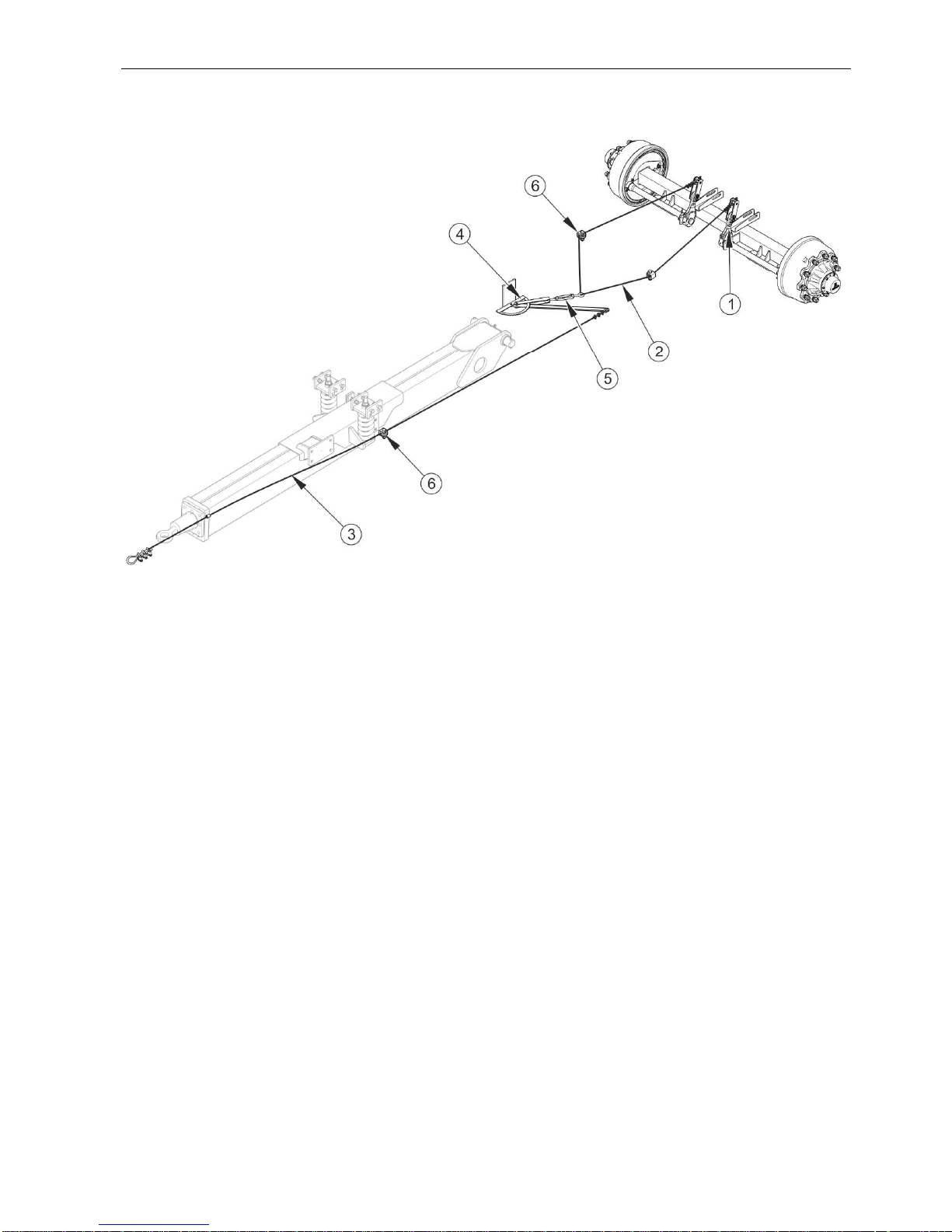
3.2.4 EMERGENCY BRAKE
T700XL trailer can be equipped with emergency brake - figure (3.7) activated by means of
cables guided in rollers (6). The brake immediately stops the trailer in case of its
disconnection from the tractor.
The ends of cable I (2) are attached to expander levers (1) of wheel axle. Cable I (2) is
connected with cable II (3) through brake lever (4) with proper leverage and bottle screw (5).
The end of cable II is attached to a fixed element of the tractor.
SECTION 3 Pronar 669XL, Pronar T700XL
3.11
FIGURE 3.7 Emergency brake design
(1) expander arm, (2) cable I, (3) cable II, (4) brake lever, (5) bottle screw, (6) guide roller
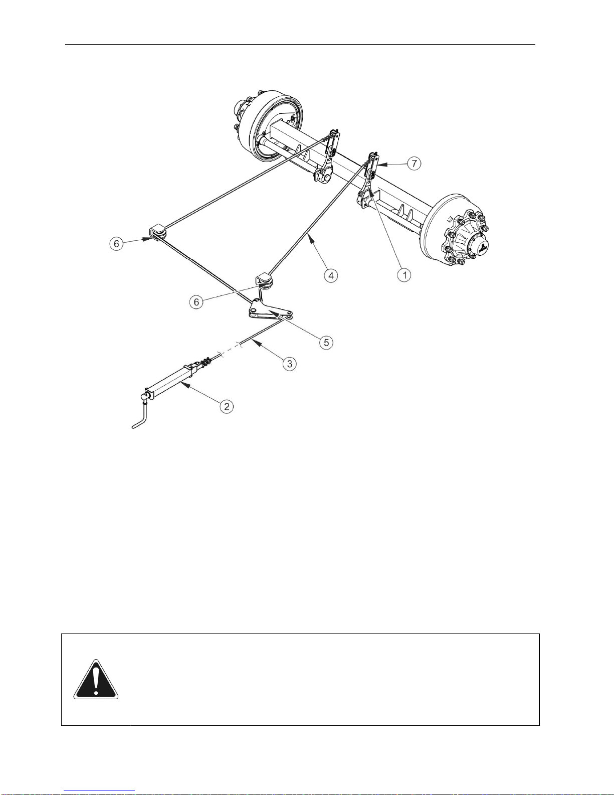
3.2.5 PARKING BRAKE
The parking brake is used for immobilising trailer while standing motionless. System
construction is shown in Figure (3.8). The brake crank mechanism (2) is welded to the left
longitudinal member of the lower frame on the front of the trailer. Expander levers (1) of
wheel axle are connected to lever (5) through arm (7), by means of cable II (4) guided in
rollers (6). Lever (5) is connected to the brake crank mechanism (2) by means of steel cable I
(3).
Tensioning cable I (3) (turning the crank mechanism clockwise), causes deflection of the
lever (5) and tension of cable II (4) causing a deflection of the brake expander arms (1),
which immobilize the trailer by parting the brake shoes.
Pronar 669XL, Pronar T700XL SECTION 3
3.12
FIGURE 3.8 Parking brake design
(1) expander arm, (2) brake crank mechanism (3) steel cable I, (4) steel cable II (5) lever,
(6) guide roller, (7) arm
3.2.6 HYDRAULIC TIPPING SYSTEM
Hydraulic tipping system serves for automatic unloading of trailer by tipping the load box to
the rear. The hydraulic tipping system is supplied with oil from the tractor's hydraulic system.
Hydraulic oil selective control valve of the tractor's external hydraulic system is used to
control the load box tipping mechanism.
ATTENTION
Cut-off valve (3) – figure (3.9) limits the tipping angle of the load box when
tipped to the rear. The length of the control cable (6) controlling this valve is
factory adjusted by the Manufacturer and must not be changed when the trailer
is used.

SECTION 3 Pronar 669XL, Pronar T700XL
3.13
TIP
The hydraulic system of the trailer is filled with L-HL32 Lotos hydraulic oil.
FIGURE 3.9 Design and diagram of the hydraulic tandem tipping system
(1) telescopic cylinder, (2) hydraulic pipe, (3) cut-off valve, (4) quick coupler, (5) hydraulic
conduit, (6) control cable, (7) guide roller
Pronar 669XL, Pronar T700XL SECTION 3
3.14
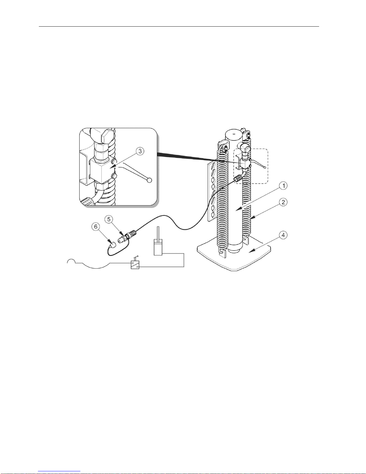
3.2.7 HYDRAULIC SYSTEM OF THE SUPPORT (OPTION)
The parking stand hydraulic system extends the stand to support the trailer disconnected
from the tractor or when it is parked in the garage after use. Using parking stand hydraulic
system, the drawbar height can be adjusted when hitching and unhitching the trailer. The
parking stand is supplied with oil by the tractor's hydraulic system. The parking stand is
extended or withdrawn by extending or withdrawing a hydraulic cylinder.
FIGURE 3.10 Design and diagram of the hydraulic system of the straight support
(1) hydraulic cylinder, (2) spring, (3) valve, (4) support foot, (5) quick coupler - plug, (6) plug
cap (red)
The trailer can be equipped with straight hydraulic support – figure (3.10) or folding hydraulic
support – figure (3.11).
Hydraulic oil manifold of the tractor's external hydraulic system is used for controlling the
support's hydraulic cylinder. If the handle is shifted perpendicularly to valve (3), the support is
locked in fixed position. The support is lowered by shifting the valve handle to open position,
i.e. along the valve. Hydraulic oil supplied from the tractor's hydraulic manifold extends the
cylinder rod to a desired height. After the pressure in hydraulic conduit is reduced, withdrawal
of the straight support to transport position is forced by means of springs - Figure (3.10). The
hydraulic conduit for controlling the support is terminated with a quick coupler - plug (5) and
protected by means of a cap (6).

SECTION 3 Pronar 669XL, Pronar T700XL
3.15
In case of the folding support, the support return spring is located inside the cylinder sleeve
(2) – figure (3.11). The support is locked in transport position or in parking position by means
of interlock pin (4).
.
FIGURE 3.11 Design and diagram of the hydraulic system of the folding support
(1) body, (2) hydraulic cylinder, (3) valve, (4) interlock pin, (5) quick coupler - plug, (6) plug
cap (red)
TIP
The hydraulic system of the support is filled with
L-HL32 Lotos hydraulic oil.
3.2.8 TAILGATE HYDRAULIC SYSTEM
The hydraulic system of the tailgate controls raising and lowering of the tailgate. The
hydraulic system is supplied with oil from the tractor external hydraulic system. Pressurised
oil is fed through hydraulic conduits (2) and (3) terminated with quick-couplers (8) to hydraulic
cylinders (1), which open or close the tailgate.

Pronar 669XL, Pronar T700XL SECTION 3
3.16
FIGURE 3.12 Design of the hydraulic system of the tailgate
(1) hydraulic cylinder, (2) hydraulic lock, (3) flow divider, (4) hydraulic conduit, (5) quick
coupler - plug, (6) plug stopper (black), (7) tailgate
The hydraulic system - figure (3.12) is used for closing and opening the tailgate.(7) The
hydraulic system is supplied with oil from the tractor external hydraulic system. Pressurised
oil is fed to flow divider (3) through hydraulic conduits (4) connected to tractor by means of
quick couplers (5). The flow divider divides the oil stream proportionally to the two hydraulic
cylinders (1) which extend or withdraw in order to close or open the tailgate. Quick couplers
(5) at the ends of the conduits are protected with black stoppers (6).

SECTION 3 Pronar 669XL, Pronar T700XL
3.17
In the initial stage of opening, the tailgate raises slightly and releases the locks in the form of
hooks (in the floor frame) and forks (in the tailgate) and then, it tilts upwards.
FIGURE 3.13 Diagram of the hydraulic system of the tailgate
(1) hydraulic cylinder, (2) two-sided hydraulic lock, (3) flow divider
3.2.9 LIGHTING SYSTEM
The trailer electrical system is designed for supply from direct current source of 12 V.
Connection of the trailer electrical system with the tractor should be made through an
appropriate connection lead.

Pronar 669XL, Pronar T700XL SECTION 3
3.18
FIGURE 3.14 Positioning of electrical components and reflective lights
(1) front parking light, (2) side parking light, (3) rear left lamp assembly, (4) rear right lamp
assembly, (5) rear left clearance light, (6) rear right clearance light, (7) 7-pin socket,
(8) reflective warning triangle, (9) license plate light

SECTION 3 Pronar 669XL, Pronar T700XL
3.19
FIGURE 3.15 Electrical system concept diagram
Marking according to table (3.2), (3.3) and (3.4)

Pronar 669XL, Pronar T700XL SECTION 3
3.20
TABLE 3.2 List of electrical component markings
SYMBOL NAME
ZP Rear right lamp assembly
ZL Rear left lamp assembly
GP Front seven pin socket
OTP Right license plate light
OTL Left license plate light
PP Front right parking light
PL Front left parking light
OP Rear right clearance light
OL Rear left clearance light
OBL1, OBL2 Left clearance lamp
OBP1, OBP2 Right clearance lamp
TABLE 3.3 Marking of GP socket connections
MARKING FUNCTION
31 Ground
+ Power supply +12V (not used)
L Left indicator
54 STOP light
58L Rear left parking light
58R Rear right parking light
R Right indicator

SECTION 3 Pronar 669XL, Pronar T700XL
3.21
TABLE 3.4 Lead colour marking
MARK COLOUR
B White
C Black
K Red
N Blue
P Orange
T Green
C/T Black and green
R Pink
O brown
Z Yellow

Pronar 669XL, Pronar T700XL SECTION 3
3.22

SECTION
4
CORRECT
USE

Pronar T669XL, Pronar T700XL SECTION 4
4.2
4.1 PREPARING THE TRAILER FOR WORK
4.1.1 PRELIMINARY INFORMATION
The trailer is supplied to the user completely assembled and does not require additional
mounting operations of machine sub-assemblies. The manufacturer guarantees that the
trailer is fully operational and has been checked according to quality control procedures and
is ready for use. This does not release the user from an obligation to check the machine's
condition after delivery and before first use.
4.1.2 HAND-OVER AND INSPECTION OF THE TRAILER AFTER DELIVERY
After delivery of the machine to the buyer, the user is obliged to check technical condition of
the trailer. While buying the machine, the user must be informed by the seller about the
method of use of the machine, risks resulting from the use for purposes other than intended,
the method of the machine hitching and the principles of the machine construction and
design. Detailed information concerning the machine hand-over are included in the
WARRANTY BOOK.
ATTENTION
The seller is obliged to conduct the first start up of the trailer in the presence of
the user.
The user trained by the seller is not released from the obligation to carefully
read this Operator's Manual and adhere to the recommendations contained in
it.
Checking the trailer after delivery
• Check completeness of the machine according to order (standard and optional
equipment).
• Check technical condition of shields and protection devices.
• Check condition of paint coating; check the machine for traces of corrosion.
• Inspect the trailer's individual components for mechanical damage resulting from,
among others, incorrect transport (dents, piercing, bent or broken components).
• Check technical condition of tyres and tyre pressure.

SECTION 4 Pronar T669XL, Pronar T700XL
4.3
• Check if the nuts and bolts fixing the wheels are properly tightened.
• Check technical condition of drawbar eye and if correctly installed.
• Check technical condition of pneumatic conduits.
• Check technical condition of elastic hydraulic conduits.
• Check that there are no hydraulic oil leaks.
• Check tipping cylinder, tailgate cylinders and support cylinder for hydraulic oil
leaks.
• Check electric lamps.
If non-conformities are found, do not hitch and start using the trailer. Discovered defects
should be notified directly to the seller in order to remove them.
4.1.3 PREPARING THE TRAILER FOR THE FIRST USE, TEST RUN OF THE
TRAILER
Preparing for the test run
• The user must read this OPERATOR'S MANUAL and observe all the
recommendations contained in it.
• Adjust the height of the drawbar eye to the tractor hitch
• Check all the trailer's lubrication points, lubricate the machine as needed
according to recommendations provided in section 5.7,
• Check if the nuts and bolts fixing the wheels are properly tightened.
• Visually inspect the trailer according to the guidelines presented in section
PREPARING THE TRAILER FOR NORMAL USE.
• Drain the air tank in the braking system - see section 5.3.4.
• Ensure that pneumatic, hydraulic and electric connections in agricultural tractor
are according to the requirements, if not the trailer should not be hitched to the
tractor.

Pronar T669XL, Pronar T700XL SECTION 4
4.4
Test start
If all the above checks have been performed and there is no doubt as to the trailer's good
technical condition, it can be connected to tractor. Start the tractor, check all systems and
conduct test run of trailer without load (no load in load box). It is recommended that the
inspection is conducted by two people, one of which should always remain in the tractor cab.
Test start should be conducted according to the sequence shown below.
Connect the trailer to appropriate hitch on agricultural tractor.
Connect conduits of braking, electrical and hydraulic systems.
Switch on individual lights, check correct operation of electrical system.
Conduct test tipping of load box.
Actuate and check if tailgate control system operates correctly.
When moving off check if the main brakes operate correctly.
Perform test drive.
TIP
Operating activities: hitching to/unhitching from tractor, adjustment of draw bar
position, tipping of load box etc. are described in detail in further parts of the
Operator's Manual, in sections 4 and 5.
If during test run worrying symptoms occur such as:
• noise and abnormal sounds originating from the abrasion of moving elements of
the trailer design,
• brake system leak,
• hydraulic oil leak,
• incorrect operation of hydraulic and/or pneumatic cylinders,
or other faults, find the cause of the problem. If a fault cannot be rectified or the repair could
void the warranty, please contact the dealer for additional clarifications or to perform repair.
After completion of test drive check tightness of wheel nuts.

SECTION 4 Pronar T669XL, Pronar T700XL
4.5
4.1.4 PREPARING THE TRAILER FOR NORMAL USE
DANGER
Careless and improper use and operation of the trailer, and non-compliance
with the recommendations given in this operator's manual is dangerous to your
health.
The trailer must never be used by persons, who are not authorised to drive
agricultural tractors, including children and people under the influence of
alcohol or other drugs.
Non-compliance with the safety rules of this Operator’s Manual can be
dangerous to the health and life of the operator and others.
Scope of inspection activities
• Visually inspect if the tyres are properly inflated. In case of doubt, carefully check
tyre pressure.
• Check technical condition of drawbar eye.
• Check correctness of electrical system operation.
• Check technical condition and completeness of shields and protection devices.
• Install the slow-moving vehicle warning sign - if the trailer is used on public roads.
4.2 HITCHING THE TRAILER TO TRACTOR AND UNHITCHING
THE TRAILER FROM TRACTOR
The trailer may be hitched only to a technically sound agricultural tractor with the electric,
pneumatic and hydraulic connections and the tractor's hitch conforming to the trailer
Manufacturer's requirements.
In order to hitch the trailer to the tractor perform the actions below in the sequence
presented.
Hitching to tractor
Visually inspect the technical condition of the trailer.
Immobilise trailer with parking brake.

Pronar T669XL, Pronar T700XL SECTION 4
4.6
Position agricultural tractor directly in front of drawbar eye.
Reverse the tractor and, if hydraulic support is used, connect the conduit to
the support according to label (6) – table (2.1) (straight hydraulic support or
folding hydraulic support).
Using the support, set the drawbar at such a height as to make it possible to
couple the machines.
If the hydraulic support is used, operate the manifold in the tractor to
raise or lower the trailer drawbar until the correct height is achieved.
If the telescopic support is used, adjust the drawbar height by rotating
the crank in proper direction - see chapter 4.2.1.
Reverse tractor, hitch trailer, check coupling lock protecting machine against
accidental unhitching.
If the agricultural tractor is equipped with an automatic coupler,
ensure that the hitching operation is completed and that drawbar eye
is secured.
Fold the support and secure it properly.
If the telescopic support is used, raise the support as described in
section 4.2.1 and secure it with securing pin (5) figure (4.1).
After folding the hydraulic support, close the support valve (3) - figure
(3.10) or (3.11) and set the manifold lever in the tractor in "neutral"
position.
When the trailer is hitched, the hydraulic folding support must be
folded and secured with lock pin (4) figure (3.11).
Turn off tractor engine. Ensure that unauthorised persons do not have access
to the tractor cab.
The trailer hitched to the tractor must be level. Empty trailer may be slightly
tilted forwards from the level (about 50mm).
If the trailer is not level, adjust the position of the trailer drawbar
hitching eye or the tractor hitch.

SECTION 4 Pronar T669XL, Pronar T700XL
4.7
Connect pneumatic system conduits (applies to double conduit pneumatic
system):
Connect pneumatic conduit marked yellow with yellow socket in
tractor.
Connect pneumatic conduit marked red with red socket in tractor.
Connect pneumatic system conduit (applies to single conduit pneumatic
system).
Connect pneumatic conduit marked black with black socket in tractor.
Connect hydraulic brake system conduit (applies to trailer version with
hydraulic brake system).
The connection socket is different than in other systems (female
socket).
Connect hydraulic tipping system conduit.
Hydraulic brake system conduit is marked according to information
decal (6) – table (2.1).
Connect conduits of the tailgate hydraulic system.
Connect the conduits to the same section of the tractor hydraulic
manifold.
Conduits of the hydraulic system of the tailgate are marked according
to information decal (6) – table (2.1).
Connect main lead supplying electrical lighting system.
DANGER
When hitching, there must be nobody between the trailer and the tractor. When
hitching the machine, tractor driver must exercise particular caution and make
sure that nobody is present in the hazard zone.
When connecting the hydraulic conduits to the tractor, make sure that the
hydraulic system of the tractor and the hydraulic system of the trailer are not
under pressure.
Ensure sufficient visibility during hitching.

Pronar T669XL, Pronar T700XL SECTION 4
4.8
ATTENTION
Trailer may only be hitched to a technically reliable tractor, which has the
appropriate hitch, required connection sockets for braking, hydraulic and
electrical systems, and hydraulic oil in both machines is of the same type and
may be mixed.
When hitching is completed, secure the electrical leads and hydraulic and
braking system conduits in such a way that they do not become entangled in
tractor's moving parts and are not at the risk of breaking or being severed when
making turns.
Ensure compatibility of oils in tractor hydraulic system and in the trailer
hydraulic system.
During connection of braking system conduits (pneumatic double conduit) the correct
sequence of conduit connection is very important. First connect the yellow connector to
yellow socket in the tractor and only then connect the red connector to the red socket in the
tractor. Once the second conduit is connected, the brake applying system will switch to
normal mode of operation (when pressure in the trailer's air tank reaches the proper level, the
trailer's control valve will automatically switch to the position in which the machine brakes are
applied).
TIP
Hydraulic and pneumatic conduits are marked with coloured protective covers,
which identify the appropriate system conduit.
Unhitching the trailer
In order to unhitch the trailer from the tractor follow these steps.
Immobilise tractor and trailer with parking brake.
DANGER
Do NOT unhitch the trailer when the load box is raised.
Exercise caution when unhitching the trailer from the tractor. Ensure good
visibility. Unless it is necessary, do not go between tractor and trailer.
Before disconnecting conduits and drawbar eye, close tractor cab and secure it
against access by unauthorised persons. Turn off tractor engine.
Place chocks under trailer wheel.
Wheel chocks shall be so placed that one is in front of the wheel and
the second is behind wheel of rear axle - see section 2.

SECTION 4 Pronar T669XL, Pronar T700XL
4.9
Lower support to the ground.
If folding hydraulic support is used, unfold the support and lock it in
parking position using lock pin (4) - figure (3.11).
If straight or folding hydraulic support is used, open the support valve
- (figure (3.10) or (3.11)).
Operate the manifold on the tractor in the direction corresponding to
the support cylinder piston rod extension (hydraulic support).
When the support is lowered, set manifold lever in tractor to "neutral"
position.
Close the valve located next to the support to lock the support in a
fixed position.
If the trailer is equipped with the telescopic support, lower the support
as described in section 4.2.1 and secure it with securing pin (5) figure
(4.1).
Turn off tractor engine. Ensure that unauthorised persons do not have access
to the tractor cab.
Disconnect hydraulic conduits of tailgate, support and tipping system from the
tractor
Protect conduit ends with caps and place them on the hanger.
Disconnect electric lead.
Disconnect pneumatic system conduits and place them in the suitable place
on the trailer (applies to double conduit pneumatic system).
Disconnect pneumatic conduit marked red.
Disconnect pneumatic conduit marked yellow.
Disconnect pneumatic system conduits and place them in the suitable place
on the trailer (applies to single conduit pneumatic system).
Disconnect pneumatic conduit marked black.
Disconnect hydraulic brake system conduit and place it on the hanger (applies
to trailer version with hydraulic brake system).

Pronar T669XL, Pronar T700XL SECTION 4
4.10
Unlock tractor hitch and disconnect trailer drawbar from tractor hitch and drive
tractor away.
ATTENTION
If the ball hitch is used, first unlock the tractor hitch and then raise the drawbar
by means of the support and drive the tractor away from the machine.
4.2.1 TELESCOPIC SUPPORT OPERATION
Proper height of drawbar eye in relation to tractor hitch can be set using the telescopic
support with mechanical gear - figure (4.1).
Position (C) is used for fast rising and lowering the support foot in order to reduce the
distance between the support foot and the ground. Position (B) is used for lowering and rising
the drawbar of unloaded trailer. In position (B), the support foot (2) moves slowly and a large
force is not required to raise the machine drawbar.
FIGURE 4.1 Adjusting the drawbar height
(1) telescopic support, (2) support foot, (3) crank, (4) gear, (5) securing pin, (A) neutral
position, (B) position – I gear (speed under load), (C) position – II gear (high speed)

SECTION 4 Pronar T669XL, Pronar T700XL
4.11
Raising the support
Remove safety pin (5).
Move support crank (3) from neutral position (A) to position (B).
Turn the crank in proper direction in order to raise the support foot (2)
maximally upwards.
Install securing pin.
Place crank in neutral position (A).
Lowering the support
Remove safety pin.
Move crank (3) to position (B) or (C).
Turn the crank in proper direction in order to lower the support to the ground
or adjust the drawbar eye height in relation to the hitch (if the trailer is to be
hitched to tractor)
4.3 LOADING AND SECURING LOAD
4.3.1 GENERAL INFORMATION ABOUT LOADING
ATTENTION
The trailer is also designed for transport of harvested crops and agricultural
products (volumetric or poured). It is permissible to transport other loads
(timber, building materials packed loads), on the condition of securing the load
box against damage (abrasion of paint covering, corrosion etc.).
DANGER
People or animals must not be carried on the trailer.
During work, keep a safe distance from overhead electric power lines.
Ensure that during unloading / loading or raising the load box nobody is near
the trailer. Before tipping load box ensure that there is visibility and make
certain that there are no bystanders.
The load on the trailer must be secured against slipping and contaminating the
road during travel. If it is not possible to properly secure the load, do not
transport it.
Pronar T669XL, Pronar T700XL SECTION 4
4.12
Before beginning loading make certain that the tailgate and chute slide gate are properly
closed and secured. The trailer must be level, positioned to travel forwards and hitched to the
tractor. Loading should only take place, when trailer is placed on flat level surface and
hitched to tractor. If the trailer is equipped with tarpaulin cover, it should be rolled.
Regardless of the type of load carried, the user is obliged to secure it in such a manner that
the load is unable to spread and cause contamination of the road. If this is impossible, do
NOT transport this type of load.
Materials, which in contact with painted or steel surfaces may cause damage, should be
transported in sealed packaging (bags, boxes, barrels, etc.). After unloading, the load box
should be thoroughly cleaned with a strong jet of water.
If the transported materials exert high local pressure on the load box platform it should be
protected against damage using thick planks, plywood or other materials of similar properties.
ATTENTION
Always aim at distributing the load uniformly in the load box.
Do NOT exceed the maximum carrying capacity of the trailer specified on the
data plate.
In many cases, the use of the entire cargo space is not allowed because it
leads to exceeding trailer's nominal carrying capacity.
During loading the trailer, the drawbar eye and the tractor hitch are subjected to
great vertical loads.
Due to the various density of materials, using the total load box capacity may cause
exceeding permissible carrying capacity of the trailer. Guideline specific weight of selected
materials is shown in table (4.1). Take special care not to exceed the maximum carrying
capacity of the trailer specified on the data plate.
TABLE 4.1 Guideline weights by volume of selected loads
TYPE OF MATERIAL
WEIGHT BY VOLUME
kg/m3
Root crops:
raw potatoes
steamed crushed potatoes
dried potatoes
700 - 820
850 - 950
130 - 150

SECTION 4 Pronar T669XL, Pronar T700XL
4.13
TYPE OF MATERIAL
WEIGHT BY VOLUME
kg/m
3
sugar beet - roots
fodder beet - roots
560 - 720
500 - 700
Organic fertilisers:
old manure
mature manure
fresh manure
compost
dry peat
700 - 800
800 - 900
700 - 750
950 – 1,100
500 - 600
Mineral fertilisers:
ammonium sulphate
potash salt
super phosphate
basic slag phosphate
potassium sulphate
milled lime fertiliser
800 - 850
1,100 – 1,200
850 – 1,440
2,000 – 2,300
1,200 – 1,300
1,250 - 1,300
Building materials:
cement
dry sand
wet sand
solid bricks
hollow bricks
stones
soft wood
hard sawn timber
impregnated timber
steel structures
milled burnt lime
cinders
gravel
1,200 – 1,300
1,350 – 1,650
1,700 – 2,050
1,500 – 2,100
1,000 – 1,200
1,500 – 2,200
300 - 450
500 - 600
600 - 800
700 – 7,000
700 - 800
650 - 750
1,600 – 1,800
straw litter and bulk feeds
meadow hay dried in the swath
10 - 18

Pronar T669XL, Pronar T700XL SECTION 4
4.14
TYPE OF MATERIAL
WEIGHT BY VOLUME
kg/m
3
hay wilted in the swath
hay in gathering trailer (dry wilted)
wilted cut hay
dry baled hay
wilted baled hay
stored dry hay
stored cut hay
clover (lucerne) wilted in the swath
clover (lucerne) cut wilted on trailer
clover (lucerne) wilted on gathering trailer
dry stored clover
cut dry stored clover
dry straw in round bales
damp straw in round bales
cut damp straw in bulk trailer
cut dry straw in bulk trailer
cut dry straw in gathering trailer
cut dry straw in stack
baled straw (lightly crushed)
baled straw (heavily crushed)
cereal mass in round bales
cut cereal mass in bulk trailer
cut cereal mass in gathering trailer
green fodder in swath
cut green fodder in bulk trailer
green fodder in gathering trailer
fresh beet leaves
cut fresh beet leaves
beet leaves in gathering trailer
15 - 25
50 - 80
60 - 70
120 - 150
200 - 290
50 - 90
90 - 150
20 - 25
110 - 160
60 - 100
40 - 60
80 - 140
8 - 15
15 - 20
50 - 80
20 - 40
50 - 90
40 - 100
80 - 90
110 - 150
20 - 25
35 - 75
60 - 100
28 - 35
150 - 400
120 - 270
140 - 160
350 - 400
180 - 250
Concentrated feeds and mixed feeds:
stored chaff
pressed cake
200 - 225
880 – 1,000

SECTION 4 Pronar T669XL, Pronar T700XL
4.15
TYPE OF MATERIAL
WEIGHT BY VOLUME
kg/m
3
milled dry feed
mixed feeds
mineral mixtures
ground oats
wet sugar beet pulp
pressed sugar beet pulp
dry sugar beet pulp
bran
bone meal
pasture salt
molasses
silage (pit silo)
hay silage (tower silo)
170 - 185
450 - 650
1,100 – 1,300
380 - 410
830 - 1,000
750 - 800
350 - 400
320 - 600
700 – 1,000
1,100 – 1,200
1,350 – 1,450
650 – 1,050
550 - 750
Seeds and grains:
beans
mustard
peas
lentils
runner beans
barley
clover
grass
maize
wheat
oil seed rape
linseed
lupins
oats
lucerne
rye
750 - 850
600 - 700
650 - 750
750 - 860
780 - 870
600 - 750
700 - 800
360 - 500
700 - 850
720 - 830
600 - 750
640 - 750
700 - 800
400 - 530
760 - 800
640 - 760
Others:
dry soil
1,300 – 1,400

Pronar T669XL, Pronar T700XL SECTION 4
4.16
TYPE OF MATERIAL
WEIGHT BY VOLUME
kg/m
3
wet soil
fresh peat
garden soil
1,900 – 2,100
700 - 850
250 - 350
Source: "Technology of machine work in agriculture”, PWN, Warszawa 1985
Loading should be carried out by a person experienced in this type of work and having
appropriate authorisation for operating equipment (if required).
Loose bulk material
Loading bulk materials is normally conducted with the use of loaders or conveyors and
possibly loading manually. Do not load bulk materials to a height greater than that of side
walls or extensions. On completion of loading, the load should be evenly spread over the
whole surface of the load box.
Oilseed rape or seeds of other plants of very small size or powder materials can be
transported provided the load box is properly sealed in places where gaps are bigger than
the seed diameter or other carried material. Profiled rubber seals, silicone sealers, plastic
wrap, rope or textile materials are recommended materials to provide sealing of the load box.
Additionally, it is recommended to protect the load with tarpaulin cover. It protects the load
against spilling during travel, being blown away by the wind and also protects load against
moisture. This is particularly dangerous in the case of bulk materials. They may absorb a
significant amount of water, which may increase the bulk of the load during travel. In extreme
cases the gross weight of the trailer may exceed the permissible vehicle gross weight.
Some bulk loads (e.g. building materials, such as gravel or slag) may cause more rapid
damage to paintwork.
Loads of pieces or solid lumps
Loads of pieces or solid lumps are generally hard materials of significantly greater
dimensions than bulk loads (stones, coal, bricks and ballast). These materials without prior
preparation of the load box may cause indentation of the floor or sidewalls and abrasion of
paintwork. To provide necessary protection, lay thick plywood, hard particle board, thick
planks or other materials of similar properties on the load box platform and possibly sidewalls
and extensions. Non-compliance with the instructions provided could invalidate the warranty.

SECTION 4 Pronar T669XL, Pronar T700XL
4.17
Loading of material in pieces or solid lumps must be from a low height. The load must not fall
with great force on the floor of the load box, even if it is protected.
Hazardous loads
According to the European ADR agreement concerning the international road transport of
hazardous materials, the transport of this type of load (defined in detailed by this agreement)
is forbidden with the use of agricultural trailers. The only exception are plant protection
materials and artificial fertilisers, which may be transported on agricultural trailers on the
condition that they are transported in the appropriate packaging and in quantities envisaged
by the ADR agreement.
DANGER
If it is necessary to carry permitted hazardous materials, acquaint yourself with
the regulations concerning transport of hazardous materials in force in the
given country and also the regulations of the ADR agreement.
Carefully read the information leaflets provided by the load manufacturer, and
to observe the instructions for transporting and handling the load. Ensure
whether during loading work it is necessary to apply additional personal
protection (masks, rubber gloves etc.)
High volume loads
High-volume loads such as hay, round or rectangular bales, straw, green fodder, etc. are
recommended to be loaded using proper equipment: round bale grabs, rectangular bale
grabs, etc. The load must not be higher than the load box wall extensions. Otherwise, the
trailer will exceed the maximum height of 4m allowed for vehicles on public roads.
Loads in packaging
Loads transported in packaging (boxes, sacks) must be laid closely side-by-side beginning
from the front side of the trailer. If it is essential to lay several layers, particular groups should
be stacked alternately (in block system). The load must be laid tightly together and on the
whole surface of the trailer floor. Otherwise, the load will move during travel. Due to the trailer
design (the load box designed for the transport of agricultural crops and products, lack of
load securing points), materials in packaging may not be loaded above the top of the walls or
extensions of load box.

Pronar T669XL, Pronar T700XL SECTION 4
4.18
DANGER
Overloading the trailer, erroneous loading and securing of the load is the most
frequent cause of accidents during transport.
If there is a danger of load packaging moving, do NOT transport this type of
material. A moving load constitutes a serious hazard during travel for the tractor
driver and other road users.
The load must be arranged in such a way that it does not threaten the stability
of the trailer and does not hinder driving.
The arrangement of the load may not cause an overload on the axle or hitch
system of the trailer.
Materials which may cause corrosion of steel, chemical damage or react in any other way
negatively affecting the trailer structure may be transported only on condition of appropriate
load preparation. Materials must be tightly packed (in plastic foil sacks, plastic containers
etc.). During transport, packaging contents may not come into contact with load box.
Therefore, ensure the appropriate tightness of containers.
It is impossible to describe all methods of loading due to the diversity of materials, tools,
means of fixing and securing a load. The trailer user must carefully read the regulations
concerning road transport and comply with them.
4.4 TRANSPORTING LOADS
When driving the tractor with the trailer on public roads, comply with the road traffic
regulations. Listed below are the key guidelines for driving the tractor and trailer combination.
• Before moving off make sure that there are no bystanders, especially children,
near the trailer or the tractor. Take care that the driver has sufficient visibility.
• Make sure that the trailer is correctly attached to the tractor and tractor's hitch is
properly secured.
• Vertical load borne by the trailer drawbar eye affects the steering of the
agricultural tractor.
• The trailer must not be overloaded, loads must be uniformly distributed so that the
maximum permissible axle loads are not exceeded. The trailer's maximum

SECTION 4 Pronar T669XL, Pronar T700XL
4.19
carrying capacity must not be exceeded as this can damage the trailer and pose a
risk to the operator or other road users.
• Permissible design speed and maximum speed allowed by road traffic law must
not be exceeded. The driving speed should be suitable for the current road
conditions, the trailer load, type of load carried and other conditions relevant for
driving performance of the trailer.
• When not connected to the tractor, the trailer must be immobilised using parking
brake and possibly also with chocks or other objects without sharp edges placed
under the front and back wheels. Do NOT leave unsecured trailer. In the event of
machine malfunction, pull over on the hard shoulder avoiding any risk to other
road users and position reflective warning triangle according to traffic regulations.
• When driving on public roads, the trailer must be marked with a slow-moving
vehicle warning sign attached to the rear wall of load box, if the trailer is the last
vehicle in the group.
• While driving on public roads the trailer must be fitted with a certified or
authorised reflective warning triangle.
• Comply with all road traffic regulations and keep all road lights and indicator lights
clean at all times and ensure they are in good condition. Any damaged or lost
lamps or indicator lights must be immediately repaired or replaced.
• Avoid ruts, depressions, ditches or driving on roadside slopes. Driving across
such obstacles could cause the trailer or the tractor to suddenly tilt. This is of
special importance because loaded trailer's centre of gravity is higher (especially
a high volume load), which reduces safety. Driving near ditches or channels is
dangerous as there is a risk of the wheels sliding down the slope or the slope
collapsing.
• Speed must be sufficiently reduced before making a turn or driving on an uneven
road or a slope.
• When driving, avoid sharp turns especially on slopes.

Pronar T669XL, Pronar T700XL SECTION 4
4.20
ATTENTION
Travelling with a high-volume load over ruts, ditches, roadside slopes etc.
constitutes a great risk of overturning the trailer. Exercise particular caution.
• Please note that the braking distance of the tractor and trailer combination is
substantially increased at higher speeds and loads.
• Monitor trailer's behaviour when travelling on an uneven terrain, and adjust driving
speed to road conditions, slow down early enough when turning.
• Driving the trailer across the ground with steeper slopes may cause the trailer to
tip over as a result of loss of stability. Prolonged driving across steep ground may
lead to loss of braking efficiency.
4.5 UNLOADING
The trailer is equipped with hydraulic tipping system and suitable frame structure and the
load box allowing tipping to the rear. Tipping of the load box is controlled from driver's cab
using external tractor hydraulic system selective control valve.
Unloading trailer is performed in the following sequence:
tractor with trailer must be placed to drive forwards on flat and hard ground,
immobilise tractor with parking brake,
open the trailer tailgate by means of hydraulic cylinders by operating a lever of
the tractor hydraulic manifold,
raise the load box by means of the manifold lever in the tractor cab,
after unloading, lower the load box and clean the floor edges,
close the tailgate by operating the suitable hydraulic circuit from the tractor,
Tailgate must be closed until the tailgate forks are locked in the load
box hooks,
before moving off make sure that the tailgate is properly locked,
remove remains of load from the trailer.

SECTION 4 Pronar T669XL, Pronar T700XL
4.21
ATTENTION
Tipping may only be performed when trailer is hitched to tractor.
Tipping the load box must be done on hard and level ground.
Do NOT tip load box in strong gusty winds conditions.
Do NOT move off or drive when load box is raised.
Before unloading the trailer, check that the pins connecting the load box with
the lower frame are properly secured.
Do NOT jerk the trailer forwards if load is bulky or reluctant to pour and does
not unload.
While unloading bulky materials be especially careful. Do NOT tip load box on uneven or wet
ground and move and jerk trailer during unloading. Bulky materials are normally difficult to
unload. Therefore, proceed cautiously and patiently. Careless operation of trailer may pose a
danger to operators and bystanders can also cause damage to the machine.
FIGURE 4.2 Chute
(1) chute slide gate, (2) chute, (3) lever, (4) locking bolt

Pronar T669XL, Pronar T700XL SECTION 4
4.22
DANGER
Ensure that during unloading nobody is near tipped load box or load material
pouring out.
When closing the rear grain chute gate take particular care to avoid crushing
fingers.
Rear load box wall is equipped with chute slide gate (1) – figure (4.2) and chute (2) (optional
equipment) which is used for unloading loose materials. Chute design allows very accurate
dosing of the material to packaging (sacks, boxes etc.). The opening gap can be controlled
using lever (3). In order to do that loosen the bolt interlocking slide gate (4), open the slide as
required and lock again using the bolt. During unloading through chute, load box must be
raised slowly and smoothly. Raising the load box quickly will exert large pressure on the rear
part of the load box due to displacement of the carried material and could compromise
trailer's stability.
4.6 PROPER USE AND MAINTENANCE OF TYRES
• When working on the tyres, chocks or other objects without sharp edges should
be placed under the wheels of the trailer to prevent it from rolling. Wheel may be
taken off the trailer axle only when the trailer is not loaded.
• Repair work on the wheels or tyres should be carried out by persons trained and
entitled to do so. This work should be carried out using appropriate tools.
• Inspect tightness of wheel nuts after the first use of the trailer, every 2 - 3 hours
during first month of work and then every 30 hours of use (travel). The inspection
should be repeated individually if a wheel has been removed from the wheel axle.
Wheel nuts should be tightened according to recommendations provided in
section 5 MAINTENANCE.
• Regularly check and maintain correct air pressure in tyres according to Operator's
Manual (especially if trailer is not used for a longer period).
• Pressure and tyres should be also checked during the whole day of intensive
work. Please note that higher temperatures could raise tyre pressure by as much
as 1 bar. At high temperatures and pressure, reduce load or speed.

SECTION 4 Pronar T669XL, Pronar T700XL
4.23
• Do not release air from warm tyres to adjust the pressure or the tyres will be
underinflated when temperatures return to normal.
• Tyre valves should be protected with caps to avoid soiling.
• Do not exceed the trailer's maximum design speed.
• When the trailer is operated all day, stop working for a minimum of one hour in
the afternoon.
• Adhere to 30 minutes rest for cooling tyres after driving 75 km or after 150
minutes continuous travel depending on which occurs first.
• Avoid potholes, sudden manoeuvres or high speeds when turning.

Pronar T669XL, Pronar T700XL SECTION 4
4.24

SECTION
5
MAINTENANCE

Pronar T669XL, Pronar T700XL SECTION 5
5.2
5.1 PRELIMINARY INFORMATION
When using the trailer, regular inspections of its technical condition are essential and the
performance of maintenance procedures, which keep the machine in good technical
condition. In connection with this the user of the trailer is obliged to perform all the
maintenance and adjustment procedures defined by the Manufacturer.
ATTENTION
Repairs during the warranty period may only be performed by authorised
service points.
Detailed procedures and extent of activities which the user may perform by himself are
described in this section. In the event of unauthorised repairs, changes to factory settings
and other actions, which are not regarded as possible for the trailer operator to perform, the
user shall invalidate the warranty.
5.2 MAINTENANCE OF BRAKES AND AXLES
5.2.1 PRELIMINARY INFORMATION
Work connected with the repair, change or regeneration of axle and brakes elements should
be entrusted to specialist establishments, having the appropriate technology and
qualifications for this type of work.
The responsibilities of the user are limited to:
• initial inspection of axle brakes,
• inspection and adjustment of slackness of axle bearings,
• mounting and dismounting wheel, inspection of wheel tightening,
• checking air pressure, evaluating technical condition of wheels and tyres,
• mechanical brakes adjustment,
Procedures connected with:
• changing grease in axle bearings,
SECTION 5 Pronar T669XL, Pronar T700XL
5.3
• changing bearings, hub seals,
• changing brake linings, repairing brake,
may be performed by specialist workshops.
DANGER
Do NOT use the trailer when brake system is unreliable.
5.2.2 INITIAL INSPECTION OF AXLE BRAKES
Initial inspection of axle brakes must be conducted:
• after first use,
• after first travel with load.
After purchasing trailer, the user is responsible for general checking of brake system of trailer
axle.
Inspection procedures
Hitch trailer to tractor and place chocks under trailer wheel.
Check fixing of cylinder and return springs.
Engage and release in turn the main brake and then the trailer parking brake.
Main brake and parking brake should be engaged and released
without great resistance and severity.
Check cylinder movement and correct return of piston to start position.
The help of a second person is required, who shall engage trailer
brake.
Check if axle elements are in place, (cotter pins in castellated nuts, expansion
rings etc.).
Check hydraulic cylinders or pneumatic cylinders for tightness - compare
sections 5.3.2 and 5.4.2.
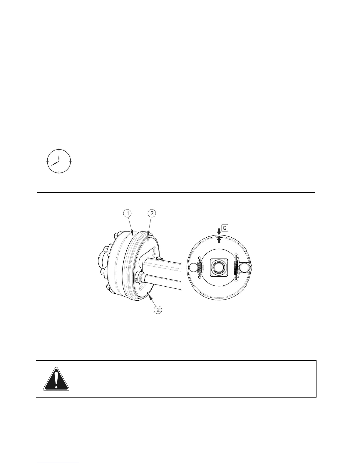
Pronar T669XL, Pronar T700XL SECTION 5
5.4
5.2.3 CHECKING BRAKE SHOE LININGS FOR WEAR
During use of trailer, friction lining of brake drums is subject to wear. In such a case, the
complete brake shoes should be replaced with new ones. Excessive wear of brake shoes is
the condition in which the thickness of linings which are glued or riveted to steel structures of
brake shoes is smaller than the minimum value. Check brake shoe linings for wear through
the inspection opening (2) – see Figure (5.1).
Check brake shoe linings for wear:
• every 6 months,
• if brakes overheat,
• if brake cylinder piston stroke is significantly longer,
• if there are unusual noises from the drum of wheel axle.
FIGURE 5.1 Checking brake shoe linings
(1) wheel axle drum, (2) inspection opening for checking wear of brake shoe linings, (G)
brake shoe lining thickness
ATTENTION
Minimum thickness of the trailer brake linings is 5 mm.

SECTION 5 Pronar T669XL, Pronar T700XL
5.5
5.2.4 CHECKING WHEEL AXLE BEARINGS FOR SLACKNESS
FIGURE 5.2 Lifting jack support point
(1) axle, (2) suspension spring, (3) absorber plate
DANGER
Before commencing work the user must read the instructions for lifting jack and
adhere to the manufacturer's instructions.
The lifting jack must be stably supported on the ground and absorber plate.
Ensure that trailer shall not move during inspection of axle bearing slackness.
Preparation procedures
Hitch trailer to tractor, immobilize tractor with parking brake.
Park tractor and trailer on hard level ground.
Tractor must be placed to drive forward.
Place the wheel chocks under the wheel opposite to the lifted wheel. Ensure
that trailer shall not move during inspection.
Raise the wheel (opposite to the side where chocks are placed).

Pronar T669XL, Pronar T700XL SECTION 5
5.6
The lifting jack should be placed under the absorber plate (3) fixing the
axle (1) to the suspension spring (2) - figure (5.2). Recommended
support point is marked with an arrow. Lifting jack must be suitable for
the weight of trailer.
Checking wheel axle bearings for slackness
Turning the wheel slowly in both
directions check that movement is
smooth and that the wheel rotates
without excessive resistance.
Turn the wheel so that it rotates
very quickly, check that the bearing
does not make any unusual sounds.
Moving the wheel try to detect
slackness.
You may use a lever placed
under the wheel supporting the
other end of the lever on the
floor.
Repeat the procedure for each
wheel individually, remembering
that the jack must be on the side
opposite to the chocks.
.
FIGURE 5.3 Checking bearings for
slackness
If slackness is felt, adjust bearings. Unusual sounds coming from bearing may be symptoms
of excessive wear, dirt or damage. In such an event, the bearing, together with sealing ring,
should be replaced with new parts, or cleaned and greased again. During inspection of
bearings ensure that possibly detected slackness comes from the bearing and not from the
suspension system (e.g. slackness of leaf spring pins etc.).

SECTION 5 Pronar T669XL, Pronar T700XL
5.7
TIP
If hub cover is damaged or missing, contamination and dampness enter the
hub, which causes significantly faster wear of bearing and hub seals.
Life of bearings is dependent on working conditions of the trailer, loading,
speed of travel and lubrication conditions.
Check condition of hub cover, if necessary replace it with a new cover. Inspection of bearing
slackness may only be conducted when the trailer is hitched to tractor and the load box is
empty and not raised.
Check wheel axle bearings for slackness:
• after travelling the first 1,000 km,
• after intensive use of trailer,
• every six months use or every 25,000 km.
5.2.5 ADJUSTMENT OF SLACKNESS OF WHEEL AXLE BEARINGS
The wheel should turn smoothly without stiffness or detectable resistance not originating from
abrasion of brake shoes in brake drum. Adjustment of bearing slackness may only be
conducted, when the trailer is hitched to a tractor and the load box is empty.
Preparation procedures
Prepare tractor and trailer for adjustment procedures according to description
provided in section 5.2.4.
Adjustment of slackness of wheel axle bearing
Take off hub cover (1) – figure (5.3).
Take out cotter pin (3) securing castellated nut (2).
Tighten castellated nut in order to eliminate slackness.
Wheel should rotate with insignificant resistance.
Undo nut (not less than 1/3 rotation) to align the nearest thread groove with
the opening in wheel axle pin. Wheel should rotate without excessive
resistance.

Pronar T669XL, Pronar T700XL SECTION 5
5.8
Nut must not be excessively tightened. Do not apply excessive
pressure because working conditions of the bearings may deteriorate.
Secure castellated nut with cotter pin and mount the hub cap.
Delicately tap the hub cap with rubber or wooden mallet.
FIGURE 5.4 Adjustment of slackness of axle bearings
(1) hub cover, (2) castellated nut, (3) cotter pin
TIP
If the wheel is dismounted, bearing slackness is easy to check and adjust.
5.2.6 MOUNTING AND DISMOUNTING WHEEL, INSPECTION OF WHEEL NUT
TIGHTENING.
Dismounting wheel
Immobilise trailer with parking brake.
Place the wheel chocks under the wheel opposite to the dismantled wheel.
Ensure that trailer shall not move during wheel dismounting.

SECTION 5 Pronar T669XL, Pronar T700XL
5.9
Loosen wheel nuts according to sequence shown in figure (5.5).
Place a lifting jack and raise the trailer to a sufficient height so that the wheel
to be replaced does not touch the ground.
The lifting jack should have sufficient lifting capacity and should be
technically reliable.
The lifting jack must be positioned on a level and hard surface so as to
prevent sinking into the ground or relocating the jack during lifting.
If necessary, use proper backing plates in order to reduce unit
pressure of the jack's base on the ground and prevent its sinking into
the ground.
Dismount wheel.
Wheel mounting
TIP
Wheel nuts should be tightened using the torque of 450 Nm - M22x1.5 nuts.
Clean axle pins and nuts of contamination.
Do not grease thread of nuts and pins.
Check condition of pins and nuts, if necessary replace them.
Place wheel on hub, tighten nuts so that wheel rim tightly fits the hub.
Lower the trailer, tighten nuts according to recommended torque and given
sequence.
ATTENTION
Wheel nuts may not be tightened with impact wrench because of danger of
exceeding permissible tightening torque, the consequence of which may be
breaking the thread connection or breaking off the hub pin.
The greatest precision is achieved using a torque spanner. Before commencing
work, ensure that correct tightening torque value is set.

Pronar T669XL, Pronar T700XL SECTION 5
5.10
Tightening nuts
Nuts should be tightened gradually diagonally,
(in several stages, until obtaining the required
tightening torque) using a torque spanner.
Tightening of nuts should be checked with the
frequency given in the below table.
Checking wheel tightening:
• After the first use of trailer (one-time inspection).
• Every 2 – 3 hours of trailer travel (during the first month of trailer
use).
• Every 30 hours of trailer travel.
• The above actions should be repeated individually if a wheel has
been removed from the wheel axle.
5.2.7 CHECKING AIR PRESSURE IN TYRES, EVALUATING TECHNICAL
CONDITION OF TYRES AND STEEL WHEELS
Air pressure in tyres should be checked each time after changing a spare wheel and at least
once a month. In the event of intensive use, air pressure in tyres should be checked more
frequently. During this time, the trailer must be unloaded. Checking should be done before
travelling when tyres are not heated, or after an extended period of parking.
TIP
Tyre pressure values are specified in information decal, placed on wheel or on
upper frame above trailer wheel.
FIGURE 5.5 Sequence of tightening
and undoing nuts
SECTION 5 Pronar T669XL, Pronar T700XL
5.11
While checking pressure pay attention to technical condition of wheels and tyres. Look
carefully at tyre sides and check the condition of tread. In case of mechanical damage
consult the nearest tyre service and check whether the tyre defect requires tyre replacement.
DANGER
Damaged tyres or wheels may be the cause of a serious accident.
Wheels should be inspected with regard to distortion, breaking of material, breaking of welds,
corrosion, especially in the area of welds and contact with tyre.
Proper technical condition and appropriate maintenance of wheels significantly extends the
life of these components and ensures appropriate level of safety to trailer users.
Checking air pressure in tyres and visual inspection of steel wheels:
• every month of use,
• every week during intensive work.
5.2.8 MECHANICAL BRAKES ADJUSTMENT
Considerable wear of brake shoe linings results in increased brake cylinder piston stroke and
worse braking efficiency.
TIP
Correct brake cylinder piston stroke should be within the range of 25 – 45 mm.
During braking, the brake cylinder piston stroke should be within the specified operating
range and the angle between brake cylinder piston (1) and expander arm (3) should be about
90° – compare figure (5.8), (5.9). Trailer wheels must brake simultaneously.
Braking force decreases also when the operating angle of the brake cylinder rod (5) – figure
(5.6), (5.7) in relation to the expander arm (1) is wrong. In order to obtain the optimum
mechanical operating angle, the cylinder piston fork (6) must be installed on the expander
arm (1) in such a manner as to ensure that the operating angle at full braking is about 90°.

Pronar T669XL, Pronar T700XL SECTION 5
5.12
The inspection involves measuring the extension length of each brake cylinder rod while
braking at parking. If the brake cylinder piston stroke exceeds the maximum value (45 mm),
the braking system should be adjusted.
During dismantling of cylinder fork (6) remember or mark the original position of the cylinder
fork pin (7) - figure (5.6), (5.7). Mounting position depends on the type of the braking system
and size of the trailer tires. It is selected by the manufacturer and cannot be changed.
ATTENTION
Incorrectly adjusted brake may cause rubbing of brake shoes against brake
drums, which may lead to faster wear of brake linings and/or brake overheating.
Check technical condition of brakes:
• Before the period of intensive use.
• Every 6 months.
• After repair of braking system.
• In case of uneven trailer wheel braking.

SECTION 5 Pronar T669XL, Pronar T700XL
5.13
FIGURE 5.6 Design of pneumatic wheel axle brake
(1) expander arm , (2) expander shaft, (3) adjustment bolt, (4) pneumatic cylinder,
(5) cylinder piston rod, (6) cylinder fork, (7) cylinder pin
ATTENTION
The positions for fixing the brake cylinder in the bracket openings and the brake
cylinder pin in the expander arm are determined by the Manufacturer and must
not be changed.
Each time when dismantling the pin or brake cylinder, the original fixing position
should be marked.

Pronar T669XL, Pronar T700XL SECTION 5
5.14
FIGURE 5.7 Design of hydraulic wheel axle brake
(1) expander arm , (2) expander shaft, (3) adjustment bolt, (4) hydraulic cylinder, (5) cylinder
piston rod, (6) cylinder fork, (7) cylinder pin
TABLE 5.1 Operating parameters of cylinders
TYPE OF
CYLINDER
NOMINAL STROKE
L [MM]
MINIMUM STROKE
L
min
[MM]
MAXIMUM STROKE
L
max
[MM]
Pneumatic 75 25 45
Hydraulic 140 25 45
Required maintenance activities
Hitch trailer to tractor.
Turn off tractor engine and remove key from ignition.
Immobilise tractor with parking brake.
 Loading...