

Page 1

VT
VTJ930s
RAK
Product Manual
Version 1.0
Page 2

VTrak J930s Product Manual
Copyright
© 2012 PROMISE Technology, Inc. All Rights Reserved. PROMISE, the
PROMISE logo, VTrak, SmartStor, SuperTrak, FastTrak, VessRAID, Ve ss,
PerfectPATH, PerfectRAID, SATA150, ULTRA133, VTrak S3000, BackTrak,
HyperCache, HyperCache-R, HyperCache-W, DeltaScan and GreenRAID are
registered or pending trademarks of PROMISE Technology, Inc. in the U.S. and
other countries. All other trademarks are the property of their respective owners.
Information regarding products, services and offerings may be superseded by
subsequent documents and are subject to change without notice. For the latest
information and specifications regarding PROMISE Technology, Inc. and any of
its offerings or services, please contact your local PROMISE office or the
corporate headquarters. Visit www.promise.com for more information on
PROMISE products.
Important dat a protection information
You should ba ck up all data before installing any drive controller or storage
peripheral. PROMISE Technology is not responsible for any loss of data resulting
from the use, disuse or misuse of this or any other PROMISE Technology
product.
Notice
Although PROMISE Technology has attempted to ensure the accuracy of the
content of this document; it is possible that this document may contain technical
inaccuracies, typographical, or other errors. PROMISE Technology assumes no
liability for any error in this publication, and for damages, whether direct, indirect,
incidental, consequential or otherwise, that may result from such error, including,
but not limited to loss of data or profits.
PROMISE Technology provides this publication “as is” without warranty of any
kind, either express or implied, including, but not limited to implied warranties of
merchantability or fitness for a particular purpose. The published information in
the manual is subject to change without notice. PROMISE Technology reserves
the right to make changes in the product design, layout, and driver revisions
without notification to its users. This version of this document supersedes all
previous versions.
Recommendations
In this Product Manual, the appearance of products made by other companies,
including but not limited to software, servers, and disk drives, is for the purpose of
illustration and explanation only. PROMISE Technology does not recommend,
endorse, prefer, or support any product made by another manufacturer.
ii
Page 3

Contents
Chapter 1: Introduction to VTrak . . . . . . . . . . . . . . . . . . . . . . . . . . . . .1
About This Manual . . . . . . . . . . . . . . . . . . . . . . . . . . . . . . . . . . . . . . .1
VTrak Overview . . . . . . . . . . . . . . . . . . . . . . . . . . . . . . . . . . . . . . . . .2
Architectural Description . . . . . . . . . . . . . . . . . . . . . . . . . . . . . . . . . .3
Features and Benefits . . . . . . . . . . . . . . . . . . . . . . . . . . . . . . . . . . .4
Specifications . . . . . . . . . . . . . . . . . . . . . . . . . . . . . . . . . . . . . . . . . .5
Drive Support . . . . . . . . . . . . . . . . . . . . . . . . . . . . . . . . . . . . . . .5
External I/O Ports . . . . . . . . . . . . . . . . . . . . . . . . . . . . . . . . . . . .5
Power Supplies . . . . . . . . . . . . . . . . . . . . . . . . . . . . . . . . . . . . . .5
Operating Environment . . . . . . . . . . . . . . . . . . . . . . . . . . . . . . . .5
Noise, Shock, and Vibration . . . . . . . . . . . . . . . . . . . . . . . . . . . .6
Dimensions . . . . . . . . . . . . . . . . . . . . . . . . . . . . . . . . . . . . . . . . .6
Weight . . . . . . . . . . . . . . . . . . . . . . . . . . . . . . . . . . . . . . . . . . . . .6
Safety Standards . . . . . . . . . . . . . . . . . . . . . . . . . . . . . . . . . . . . . . . .6
Warranty . . . . . . . . . . . . . . . . . . . . . . . . . . . . . . . . . . . . . . . . . . . . . .7
Support . . . . . . . . . . . . . . . . . . . . . . . . . . . . . . . . . . . . . . . . . . . . . . .7
CE Statement . . . . . . . . . . . . . . . . . . . . . . . . . . . . . . . . . . . . . . .7
FCC Statement . . . . . . . . . . . . . . . . . . . . . . . . . . . . . . . . . . . . . .7
VCC Statement . . . . . . . . . . . . . . . . . . . . . . . . . . . . . . . . . . . . . .7
Chapter 2: Installation . . . . . . . . . . . . . . . . . . . . . . . . . . . . . . . . . . . . . .9
Unpacking the VTrak . . . . . . . . . . . . . . . . . . . . . . . . . . . . . . . . . . . . .9
Mounting the J930s Unit in a Rack . . . . . . . . . . . . . . . . . . . . . . . . .10
Mounting the Enclosure in a Rack . . . . . . . . . . . . . . . . . . . . . .11
Installing the Front Bezel . . . . . . . . . . . . . . . . . . . . . . . . . . . . . . . . .14
Installing the Cable Management Kit . . . . . . . . . . . . . . . . . . . . . . . .15
Installing Physical Drives . . . . . . . . . . . . . . . . . . . . . . . . . . . . . . . . .18
Assembling Drive Carriers for 3.5-inch Drives . . . . . . . . . . . . .18
Installing the Drive Carriers . . . . . . . . . . . . . . . . . . . . . . . . . . . .22
Making Data Connections . . . . . . . . . . . . . . . . . . . . . . . . . . . . . . . .25
Basic DAS Connection . . . . . . . . . . . . . . . . . . . . . . . . . . . . . . .25
Cascading DAS Connection . . . . . . . . . . . . . . . . . . . . . . . . . . .26
Redundant Cascading DAS Connection . . . . . . . . . . . . . . . . . .27
Connecting the Power . . . . . . . . . . . . . . . . . . . . . . . . . . . . . . . . . . .28
Power-up Sequence – Single Unit . . . . . . . . . . . . . . . . . . . . . .29
Power-up Sequence – Multiple Units . . . . . . . . . . . . . . . . . . . .29
Command Line Interface . . . . . . . . . . . . . . . . . . . . . . . . . . . . . . . . .31
iii
Page 4

VTrak J930s Product Manual
Chapter 3: Management . . . . . . . . . . . . . . . . . . . . . . . . . . . . . . . . . . .33
Front Panel LEDs . . . . . . . . . . . . . . . . . . . . . . . . . . . . . . . . . . . . . .33
Drive Carrier LED . . . . . . . . . . . . . . . . . . . . . . . . . . . . . . . . . . . . . .34
I/O Module LEDs . . . . . . . . . . . . . . . . . . . . . . . . . . . . . . . . . . . . . . .34
PCM LEDs . . . . . . . . . . . . . . . . . . . . . . . . . . . . . . . . . . . . . . . . . . . .37
Replacing Physical Drives . . . . . . . . . . . . . . . . . . . . . . . . . . . . . . . .38
Sliding the Enclosure in and out of the Rack . . . . . . . . . . . . . .38
Accessing the Drive Carriers . . . . . . . . . . . . . . . . . . . . . . . . . .39
Drive Slot Numbering . . . . . . . . . . . . . . . . . . . . . . . . . . . . . . . .41
Activating the Locator LED . . . . . . . . . . . . . . . . . . . . . . . . . . . .42
Replacing the Physical Drive . . . . . . . . . . . . . . . . . . . . . . . . . .43
Replacing a PCM . . . . . . . . . . . . . . . . . . . . . . . . . . . . . . . . . . . . . . .44
Activating the Locator LED . . . . . . . . . . . . . . . . . . . . . . . . . . . .44
Replacing the PCM . . . . . . . . . . . . . . . . . . . . . . . . . . . . . . . . .44
Replacing an I/O Module . . . . . . . . . . . . . . . . . . . . . . . . . . . . . . . . .46
Activating the Locator LED . . . . . . . . . . . . . . . . . . . . . . . . . . . .46
Replacing the I/O Module . . . . . . . . . . . . . . . . . . . . . . . . . . . .46
Shutting Down and Restarting the VTrak . . . . . . . . . . . . . . . . . . . .48
Shutdown Sequence – Single Unit . . . . . . . . . . . . . . . . . . . . . .48
Shutdown Sequence – Multiple Units . . . . . . . . . . . . . . . . . . . .48
Power-up Sequence – Single Unit . . . . . . . . . . . . . . . . . . . . . .49
Power-up Sequence – Multiple Units . . . . . . . . . . . . . . . . . . . .49
Chapter 4: Support . . . . . . . . . . . . . . . . . . . . . . . . . . . . . . . . . . . . . . .51
Frequently Asked Questions . . . . . . . . . . . . . . . . . . . . . . . . . . . . . .51
Contacting Technical Support . . . . . . . . . . . . . . . . . . . . . . . . . . . . .52
Limited Warranty . . . . . . . . . . . . . . . . . . . . . . . . . . . . . . . . . . . . . . .57
Returning the Product for Repair . . . . . . . . . . . . . . . . . . . . . . . . . . .59
Index. . . . . . . . . . . . . . . . . . . . . . . . . . . . . . . . . . . . . . . . . . . . . . . . . . . .61
iv
Page 5

Chapter 1: Introduction to VTrak
This chapter covers the following topics:
• About This Manual (below)
• VTrak Overview (page 2)
• Architectural Description (page 3)
• Features and Benefits (page 4)
• Specifications (page 5)
• Safety Standards (page 6)
• Warranty (page 7)
• Support (page 7)
Thank you for purchasing a PROMISE VTrak J930s JBOD expansion unit.
About This Manual
This Product Manual describes how to setup, use, and maintain the VTrak J930s
unit. It also describes how the WebPAM PROe management software running on
a VTrak RAID subsystem, can manage the J930s unit.
This manual refers to the VTrak J930s JBOD expansion unit in the following
interchangeable terms:
• VTrak J930s
• J930s unit
• J930s enclosure
The term RAID subsystem applies to an enclosure with a RAID controller, such
as the PROMISE VTrak E830f/i and E630f/i RAID subsystems.
This manual includes a full table of contents, index, chapter task lists and
numerous cross-references to help you find the specific information you are
looking for.
Also included are four levels of notices:
Warning
A Warning notifies you of probable equipment damage or loss of
data, or the possibility of physical injury, and how to avoid them.
1
Page 6

VTrak J930s Product Manual
Front panel LEDs
Caution
A Caution informs you of possible equipment damage or loss of
data and how to avoid them.
Important
An Important calls attention to an essential step or point required
to complete a task. Important items include things often missed.
Note
A Note provides helpful information such as hints or alternative
ways of doing a task.
VTrak Overview
The PROMISE VTrak J930s JBOD expansion units are optimized for
organizations deploying cost-effective small-to-medium application clusters, diskto-disk backup and midrange storage solutions.
Figure 1. VTrak J930s front view
The four 6 Gb/s SAS host interface ports offer the ease of management and
performance required by companies running popular departmental and backoffice applications including file, print, Email, database, and web services.
VTrak J930s JBOD expansion unit can be attached directly to a SAS HBA card in
a host PC or server. However , the J930s unit is intended to provide JBOD
expansion to a VTrak RAID subsystem.
2
Page 7

Chapter 1: Introduction to VTrak
!
!
LINK
HOST 1 HOST 2 HOST 3 HOST 4
!
!
LINK
HOST 1 HOST 2 HOST 3 HOST 4
!
AC DC
!
AC DC
I/O Module 1
PCM 1 PCM 2
I/O Module 2
Figure 2. VTrak J930s rear view
PCM stands for Power Supply/Cooling Module.
Architectural Description
The PROMISE VTrak J930s JBOD expansion unit packs up to 60 physical drives
per system, offering industry-leading capacity in just four units (4U) of standard
19-inch rack space.
Up to two J930s units can also be connected to the same RAID subsystem using
standard SAS features to deliver massive storage to capacity hungry applications
such as disk-to-disk backup, media archiving, video surveillance and compliance
storage
The four external SAS ports provide the needed connectivity and bandwidth for
large capacity solutions requiring multiple J930s units cascaded together while
still providing dual server support and host port failover or aggregation.
As implemented by PROMISE, only two of the four SAS ports are used.
With the VTrak J930s, PROMISE has dramatically narrowed the gap between
simple fault tolerance and No Single Point of Failure. The VTrak J930s expansion
unit uses a fully redundant, hot-swappable design and continuously monitors all
system components. It can withstand failures to drives, power supplies, and I/O
modules without interrupting system operation.
3
Page 8

VTrak J930s Product Manual
Features and Benefits
Feature Benefit
4U 19-inch wide enclosure Installs easily in any standard rack.
Supports Serial Attached SCSI
physical drives
Supports Serial ATA physical
drives
Supports hard disk drives (HDDs)
and solid state drives (SSDs)
Hot-swap feature for drive carriers,
I/O modules, and power supplies
Supports SBB 2.0 standard Allows controller inter-connectability with
Tool-less field-replaceable units I/O modules and power supplies can be
Complete cable-less design All components easily plug directly into
Redundant, hot-swappable power
supplies
Dual, active/active I/O Modules High level of availability even with a failed
Allows you to use the new dual-port SAS
physical drives.
Allows you to use your legacy SATA
physical drives.
Allows flexibility to use the new SSDs.
Allows a defective component to be
replaced without interrupting data
accessibility to the host system.
controllers of the same capacity from other
manufacturers.
replaced without tools, saving time and
effort for support personnel.
boards. No cables to complicate setup or
maintenance.
Load sharing and full operation even with a
failed power supply.
I/O module.
Management through in-band SAS Management does not require a separate
connection
Compatible with leading SAS HBA
and RAID cards
Supports WebPAM PROe on the
RAID subsystem
Works the first time with all major SAS HBA
or RAID adapters
In-band management via browser-based
software application
4
Page 9

Chapter 1: Introduction to VTrak
Specifications
Drive Support
• 3.5-inch and 2.5-inch form factor
• SAS drives, 6 Gb/s and 3 Gb/s
• Hard disk drives (HDDs) and solid state drives (SSDs)
• Supports any mix of SAS and SATA drives simultaneously in the same
enclosure
For a list of supported drives, go to PROMISE support:
http://www.promise.com/support/
External I/O Ports
Four 6 Gb/s SAS ports with an SFF-8088 SAS connector, per I/O module
Power Supplies
Dual 1200W, 90-264 VAC auto-ranging, 47-63 Hz, dual hot swap and redundant
with PFC, N+1 design.
Voltage
90-264 VAC
Current In
12.9 A @ 110 VAC
Current Out
• 71 A @ 12.1 VDC
• 70 A @ 5.1 VDC
• 2 A @ 3.3 VDC
Power Conversion Efficiency
90% @ 208V
Operating Environment
Temperature Range
• Operational: 5° to 35°C (41° to 95°F) at sea level.
Reduce by 2% for every 300m (1000 ft) of altitude.
• Non-Operational: -40° to 45°C (-40° to 113°F)
5
Page 10

VTrak J930s Product Manual
Humidity Range
• Operational: 20% to 80% (Non-Condensing)
• Non-Operational: 10% to 90% (Non-Condensing)
Noise, Shock, and Vibration
Acoustic Noise Levels
• Typical: 79 dB
• Maximum: 94 dB (estimated)
Shock
• Operational: 5G, 11 ms du ra ti o n
• Non-Operational: 10G, 11ms duration
Vibration
• Operational: 0.1G, 5 to 500 Hz
• Non-Operational: 1G, 5 to 500 Hz
Dimensions
(Height, Width, Depth)
4U/60 Bay: 17.7 x 42.1 x 86.4 cm (7.0 x 16.6 x 34.0 in)
Weight
• 47.6 kg/105 lbs (without drives)
• 97.5 kg/215 lbs (with drives)
Safety Standards
•CB
•CE
• FCC Class A
•TUV
6
• UL/cUL
• VCCI Class A
Page 11

Chapter 1: Introduction to VTrak
Warranty
• Three year complete system limited warranty with advanced parts
replacement
• Optional extended warranty
• Optional on-site parts replacement program
Support
• 24 hour, 7 days a week e-mail and phone support (English only)
• 24 hour, 7 days a week access to PROMISE support site
• Firmware and compatibility lists
CE Statement
Warning: This is a class A product. In a domestic environment this product may
cause radio interference in which case the user may be required to take
adequate measures.
FCC Statement
This device complies with Part 15 of the FCC Rules. Operation is subject to the
following two conditions: (1) this device may not cause harmful interference, and
(2) this device must accept any interference received, including interference that
may cause undesired operation.
VCC Statement
7
Page 12

VTrak J930s Product Manual
Warning to User: This is Class A ITE product which might cause
radio frequency interference if it is used in a residential
environment. In such case, the user would be requested to adopt
certain appropriate measures.
Notices
8
Page 13

Chapter 2: Installation
• Unpacking the VTrak (below)
• Mounting the J930s Unit in a Rack (page 10)
• Installing the Front Bezel (page 14)
• Installing the Cable Management Kit (page 15)
• Installing Physical Drives (page 18)
• Making Data Connections (page 25)
• Connecting the Power (page 28)
Please read through these instructions completely before you begin. You might
need additional items to complete your installation.
Unpacking the VTrak
The VTrak box contains the following items:
• VTrak J930s unit
• Front bezel
• Bezel mounting screws (4)
• 1.0m (3.3 ft) SFF-8088 4X to 4X
external SAS cables, 2
• Screws for physical drives
• Left and right mounting rails
• 1.5m (4.9 ft) power cables (2)
•CD with Product Manual and
Quick Start Guide
Warning
The electronic components within the VTrak are sensitive to
damage from Electro-Static Discharge (ESD). Observe
appropriate precautions at all times when handling the VTrak or its
subassemblies.
9
Page 14

VTrak J930s Product Manual
Mounting the J930s Unit in a Rack
Cautions
• Only a qualified technician who is familiar with the installation
procedure should mount and install the J930s unit.
• Do not lift the J930s unit by hand. Use a lift table to raise the
unit to the rack.
• Be sure all switches are OFF before installing the J930s unit.
• Do not lay one J930s unit on top of another. Mount each
enclosure supported by its own set of rails.
• Mount the rails to the rack using the appropriate screws and
flange nuts, fully tightened, at each end of the rail.
• Do not load the rails unless they are installed with screws as
instructed.
• The rails that ship with the J930s unit are designed to safely
support that J930s unit when properly installed. Additional
loading on the rails is at the customer’s risk.
• PROMISE Technology, Inc. cannot guarantee that the
mounting rails will support your VTrak J930s unit unless you
install them as instructed.
• Install all of your devices in the rack with their weight spread
as evenly as possible.
• Verify that the maximum ambient temperature in the rack
system is less than the J930s unit’s maximum operational
temperature of 35°C (95°F). Also see “Ope rating
Environment” on page 5.
• Verify that there is ample airflow around the J930s unit.
• Determine the maximum amperage draw of all devices in the
rack and verify that it is less than the maximum amperage for
the rack’s power circuit. See “Power Supplies” on page 5.
• Verify that all devices in the rack are properly grounded,
especially any devices attached to power strips.
Note
T o lighten the J930s enclosure, remove the power supplies. If your
J930s unit shipped with physical drives installed, remove all of the
drive carriers, also.
10
Page 15

Mounting the J930s Unit in a Rack
Rack rail attached at the front the rack
Mounting the Enclosure in a Rack
The VTrak J930s enclosure installs into your rack using the supplied mounting
rail kit.
Before you start, verify that you have these rack-mount components:
• Rack rails (one left and one right)
• Rail installation hardware (screws, guides, and bars)
• Enclosure rails (one left and one right)
The rails are marked R for right and L for left, viewing from the front of the
enclosure.
To install the J930s enclosure into a rack:
1. Loosen the screws on the left and right rack rails and adjust the lengths
accordingly to match the depth of the rack. Then re-tighten the screws.
2. Secure the rack rails to the front and rear supports of the rack, using the
screws and hardware as shown below.
Figure 1. Left rack rail, front view
11
Page 16

VTrak J930s Product Manual
Rack rail attached at the rear of the rack
Keyhole tabs
Attaching screw
J930s unit
Figure 2. Left rack rail, rear view
3. Tighten all screws securing the rack rails into the rack.
4. Position the enclosure rails on each side of the J930s unit with the rails over
the five keyhole tabs. Then slide the enclosure rails into place. See Figure 3.
Figure 3. Side rails attached to the J930s unit
5. Anchor the rail to each side of the J930s unit as shown below using a single
screw. See Figure 3.
6. Lift the J930s unit and place it in the rack with the guide blocks on top of the
rails.
12
Page 17

Mounting the J930s Unit in a Rack
Top of rack rail
Enclosure guide block
Latch release tab
Rack rail
Enclosure rail
This action removes some of the weight while connecting the rails from the
rack to the enclosure. See Figure 4.
Figure 4. Guide blocks rest on top of the sid e rails
7. Carefully engage the enclosure rails into the rack rails and slide the J930s
unit into the rack in until you hear a click. See Figure 5.
The click indicates that the enclosure rail tabs are locked into place.
Figure 5. Enclosure and rack rails
8. Push the J930s unit all the way into the rack.
This completes mounting your J930s unit in the rack.
13
Page 18

VTrak J930s Product Manual
Release tabs
Bezel alignment pins
Bezel alignment pins
Bezel alignment guides
Lightpipe assembly
This side down
Installing the Front Bezel
To install the bezel onto the front of the J930s unit:
1. Squeeze the two release tabs on the front of the J930s unit. See Figure 6.
2. Carefully pull the J930s out of the rack until the enclosure rail tabs engage.
Figure 6. Front of the J930s unit without bezel
3. Hold the bezel with the lightpipe assembly at the bottom. Position the bezel
so the alignment pins on the J930s unit slide into the alignment guides on
the inside of the bezel. See Figure 7.
Figure 7. Inside view of the bezel
14
Page 19

Installing the Cable Management Kit
Screw
Bezel
Ear
Screw
4. Insert the screws through the ears on each side of the J930s unit.
Two screws on each side. Gently tighten the screws. See Figure 8.
Figure 8. Attaching the bezel to the J930s unit
5. Press the green rail tabs on either side of the J930s.
6. Carefully push the J930s into the rack until the two release tabs engage.
Installing the Cable Management Kit
The J930s unit includes a cable management kit to organize your and SAS and
power cables in the rack. The cable guides enable you to slide the J930s unit out
of the rack without disconnecting or tangling your cables.
You must install the J930s unit in the rack before you can install the cable
management kit.
To install the cable management kit:
1. Attach one end of each cable guide as shown below to the rear of the
enclosure using the attached thumbscrews. See page 16, Figure 9.
15
Page 20

VTrak J930s Product Manual
Thumbscrews (2)
Cable guides (2)
J930s unit
Mounting pins
(1 on each side)
Rack rail
Figure 9. Cable guides attached to rear of a J930s unit
2. Attach the other end of cable guides to the rack rails using the pins from rack
rail kit. See Figure 10.
Figure 10.Cable hardware attached to rear of rack.
3. Route the SAS and power cables through the cable management rails as
shown below.
The cable management rails have slots for plastic ties or Velcro cable wraps
to hold the cables in place. See page 17, Figure 11.
16
Page 21

Installing the Cable Management Kit
Power and SAS cables Install cable wraps here
Ties and wraps are not included.
Cautions
• Do NOT plug the power cables into the power supplies at this
time.
• Use only the power cables supplied with the J930s unit. For
additional power cables, please contact PROMISE.
Figure 11.Cable guide with SAS and power cables installed
4. Test the cable management system by sliding the J930s unit all the way out
on the rails. Ensure that the unit moves smoothly and that there are no
cables loose or binding when the system is slid back into the rack.
This completes the installation of the cable management kit.
17
Page 22

VTrak J930s Product Manual
Installing Physical Drives
The VTrak J930s JBOD expansion unit supports:
• 3.5-inch and 2.5-inch form factor
• SAS drives, 6 Gb/s and 3 Gb/s
• Hard disk drives (HDDs) and solid state drives (SSDs)
• Supports any mix of SAS and SATA drives simultaneously in the same
enclosure
For a list of supported physical drives, download the latest compatibility list from
the PROMISE support web site.
Assembling Drive Carriers for 3.5-inch Drives
Caution
When handling physical drives, take static precautions, such as
wrist straps, a grounded ESD mat, etcetera.
The drive carrier consists of two parts, a release rail and a pivot rail, plus the
attaching screws.
To assemble a drive carrier:
1. Attach the release rail to the physical drive with two screws, as shown on
page 19, Figure 12.
The drive’s data/power connector is at the bottom.
2. Position the carrier pivot rail to the physical drive so that Tab A on the
release rail inserts into Slot B on the pivot rail.
3. Attach the pivot rail to the physical drive with two screws.
4. Tighten the drive carrier screws to 4 to 6 inch-pounds (0.45 to 0.67 Nm).
Do not over-tighten.
This completes drive carrier assembly. See page 19, Figure 13.
18
Page 23

Figure 12.Drive carrier with a 3.5-inch drive
Slot B
Release rail
Pivot rail
Tab A
Physical drive
Mounting
screw
Mounting
screw
Mounting
screw
Mounting
screw
Data/power connector
Handle
Pivot rail
Release
rail
Data/power connector
Physical
drive
Figure 13.Assembled drive carrier with a 3.5-inch drive
Installing Physical Drives
19
Page 24

VTrak J930s Product Manual
Assembling Drive Carriers for 2.5-inch Drives
Caution
When handling physical drives, take static precautions, such as
wrist straps, a grounded ESD mat, etcetera.
The drive carrier consists of three parts, a release rail, pivot rail, and a drive tray,
plus the attaching screws.
To assemble a drive carrier:
1. Attach the release rail to the drive tray with two screws, as shown in
Figure 14.
The tray’s data/power slot is at the bottom.
2. Position the pivot rail to the drive tray so that Tab A on the release rail inserts
into Slot B on the pivot rail.
3. Attach the pivot rail to the drive tray with one screw.
4. Tighten the drive carrier screws to 4 to 6 inch-pounds (0.45 to 0.67 Nm).
Do not over-tighten.
5. Position the physical drive into the drive tray. Line up the data/power slot on
the drive with the data/power slot on the tray, as shown in Figure 14.
6. Install and tighten the drive tray screws to 4 to 6 inch-pounds (0.45 to
0.67 Nm).
Do not over-tighten.
20
Page 25

Figure 14.Drive carrier with a 2.5-inch drive
Slot B
Release rail
Pivot rail
Tab A
Physical drive
Rail
mounting
screw
Data/power slot
Drive tray
Rail
mounting
screws
Tray mounting
screws
Handle
Pivot rail
Release
rail
Data/power connector
2.5-inch
physical
drive
Drive
tray
This completes drive carrier assembly. See page 21, Figure 15.
Figure 15.Assembled drive carrier with a 2.5-inch drive
Installing Physical Drives
21
Page 26

VTrak J930s Product Manual
Release tabs
Release handles
Pull up here
Installing the Drive Carriers
Cautions
• Ensure that physical drives are at room temperature before
installing them and powering up the J930s unit. Allow at least
two hours for the drives to acclimate to room temperature
before using them.
• To avoid hand contact with an electrical hazard, remove only
one drive carrier a time.
To install the drive carriers into the J930s unit:
1. Squeeze the two release tabs on the front of the J930s unit. See Figure 16.
Figure 16.Rack release tabs on the J930s unit
2. Carefully pull the J930s unit out of the rack until the latches engage.
3. Pull up on the release handles of the drive bay doors to unlock them.
See page 22, Figure 17.
Figure 17.Drive bay doors
22
Page 27

Installing Physical Drives
Release handles
Drive bay
Drive bay doors
Release catchHandle
Handle down
and locked
Drive carrier assembly
Handle
open
Front
4. Open the drive bay doors.
Figure 18.Drive bay open
5. Pick up a drive carrier assembly and press the release catch to release the
handle. See Figure 19.
Figure 19.Drive carrier assembly
6. Slide the drive carrier assembly into a drive slot until the carrier contacts the
Figure 20.Sliding the drive carrier assembly into a slot
7. Repeat Steps 5 and 6 for all remaining drives.
baseboard. Carefully press down on the handle until it locks the drive carrier
assembly into place. See Figure 20.
23
Page 28

VTrak J930s Product Manual
Latch release tab
8. Close the drive bay doors and press the release handles to lock them into
place.
9. Press the green latch release tabs on both sides of the J930s unit.
10. Carefully push the unit back into the rack until the front latches engage.
See Figure 21.
Figure 21.Latch release tab
When you have finished installing your drives, go to “Making Data
Connections” on page 25.
24
Page 29

Making Data Connections
VTrak J930s
SFF-8088 external
4X to 4X SAS cable
HOST 1 port
VTrak RAID
Subsystem
Making Data Connections
You can configure your VTrak J930s unit as:
• Basic Direct Attached Storage (DAS) Connection (below)
• Cascading DAS Connection (page 26)
• Redundant Cascading DAS Connection (page 27)
Basic DAS Connection
To setup a basic DAS connection:
• Connect the SAS EXP port on the VTrak RAID subsystem to the HOST 1
(SAS IN) port on the J930s unit. See Figure 22.
• Use the SFF-8088 4X to 4X external SAS cable supplied with the J930s unit.
Figure 22. A basic DAS connection
This completes data cable connections. Go to “Connecting the Power” on
page 28.
!
AC DC
HOST 1 HOST 2 HOST 3 HOST 4
LINK
!
25
!
AC DC
HOST 1 HOST 2 HOST 3 HOST 4
!
LINK
!
!
Page 30

VTrak J930s Product Manual
SFF-8088 external
4X to 4X SAS cable
VTrak J930s
VTrak J930s
VTrak RAID
Subsystem
HOST 1 port
HOST 3 port
HOST 1 port
SAS EXP port
Cascading DAS Connection
To setup a cascading DAS connection:
1. Connect the SAS EXP port on the VTrak RAID subsystem to the HOST 1
(SAS IN) port on the first J930s unit.
See Figure 23. Use a SFF-8088 4X to 4X external SAS cable (supplied with
the J930s unit).
2. Connect the HOST 3 (SAS OUT) port on the same I/O module of the first
VTrak to the HOST 1 (SAS IN) port on the second J930s unit.
You can cascade up to two J930s units in this manner.
Figure 23. A cascaded DAS connection
This completes the data cable connections. Go to “Connecting the Power” on
page 28.
!
HOST 1 HOST 2 HOST 3 HOST 4
!
HOST 1 HOST 2 HOST 3 HOST 4
!
AC DC
LINK
!
!
AC DC
HOST 1 HOST 2 HOST 3 HOST 4
!
AC DC
LINK
!
!
AC DC
LINK
!
HOST 1 HOST 2 HOST 3 HOST 4
!
LINK
!
!
26
Page 31

Making Data Connections
Redundant Cascading DAS Connection
To setup a redundant cascading DAS connectio n:
1. Connect a SAS EXP port on the VTrak RAID subsystem to the HOST 1 (SAS
IN) port on the first J930s unit.
See page 28, Figure 24. Use a SFF-8088 4X to 4X external SAS cable
(supplied with the J930s unit).
2. Connect the HOST 3 (SAS OUT) port on the same I/O module of the first
J930s unit to the SAS IN port on the second J930s unit.
3. Connect the other SAS EXP port on the VTrak RAID subsystem to the
HOST 1 (SAS IN) port to the other I/O module on the first J930s unit.
4. Connect the HOST 3 (SAS OUT) port on the same I/O module of the first
J930s unit to the HOST 1 (SAS IN) port of the other I/O module on the
second J930s unit.
5. Connect the remaining J930s units in the same manner.
Do not cross-connect the I/O modules. Maintain a separate cascade
configuration from the VTrak RAID subsystem to the last J930s unit. See
page 28, Figure 24.
You can cascade up to two J930s units in this manner.
27
Page 32

VTrak J930s Product Manual
!
!
LINK
HOST 1 HOST 2 HOST 3 HOST 4
!
!
LINK
HOST 1 HOST 2 HOST 3 HOST 4
!
AC DC
!
AC DC
!
!
LINK
HOST 1 HOST 2 HOST 3 HOST 4
!
!
LINK
HOST 1 HOST 2 HOST 3 HOST 4
!
AC DC
!
AC DC
SFF-8088 external
4X to 4X SAS cables
Cascade Configuration 1 Cascade Configuration 2
HOST 3 port
HOST 1 port
HOST 3 port
HOST 1 port
HOST 1 port
HOST 1 port
SAS EXP port SAS EXP port
VTrak RAID
subsystem
VTrak J930s
VTrak J930s
Figure 24.A redundant cascading DAS connection
This completes the data cable connections. Go to “Connecting the Power” on
page 28.
Connecting the Power
The VTrak J930s ships with clip assemblies to secure the power cables. The clips
attach to the Power Supply/Cooling Unit (PCM).
To secure the power cables:
1. Insert the barbed end of the band into the hole until it snaps into place.
2. Attach the power cables to the PCM.
Use only the power cables supplied with the J930s unit. Do not
Caution
use extension cords or any other type of power cable.
28
Page 33

Connecting the Power
Insert the barb
into the hole
Pull this tab to
position the clip
Pull this tab to
release the clip
Slide the clip to the end
of the power cables
Power supply switch PCM
3. Place the clip over the power cables, slide the clip to the end, then squeeze
the clip to tighten it. See Figure 25.
Figure 25. Securing a power cable with the clip assembly
!
AC DC
To reposition or release the clip, pull the tabs as shown.
Power-up Sequence – Single Unit
To power up a single VTrak J930s unit:
1. Switch ON both PCMs of the J930s unit.
2. Wait at least one minute and then power up the VTrak RAID subsystem.
Power-up Sequence – Multiple Units
In the power up sequence, the “first J930s” refers to the J930s unit connected to
the VTrak RAID subsystem. The “last J930s” refers to the J930s unit at the end of
the cascade.
To power up the multiple VTrak J930s units:
1. Switch ON both PCMs of the last J930s unit in the cascade.
See page 30, Figure 26.
29
Page 34

VTrak J930s Product Manual
!
!
LINK
HOST 1HOST 2HOST 3HOST 4
!
!
LINK
HOST 1 HOST 2 HOST 3 HOST 4
!
AC DC
!
AC DC
!
!
LINK
HOST 1HOST 2HOST 3HOST 4
!
!
LINK
HOST 1 HOST 2 HOST 3 HOST 4
!
AC DC
!
AC DC
last J930s
first J930s
VTrak RAID
subsystem
Step 1.
Step 2.
Step 3.
2. Wait at least one minute and then switch ON both PCMs of the first J930s
unit in the cascade.
3. Wait at least one minute and then power up the VTrak RAID subsystem.
Figure 26.Power-up sequence for cascaded units
When boot-up is finished and the J930s unit is functioning normally:
• The Power LED shows green.
• Other LEDs are dark.
See page 31, Figure 27.
30
Page 35

Command Line Interface
POWER ON
SYSTEM FAULT
SYSTEM ID
HDD FAULT
COVER OPEN
USER DEFINE 1
USER DEFINE 2
USER DEFINE 3
POWER ON
SYSTEM FAULT
SYSTEM ID
HDD FAULT
COVER OPEN
USER DEFINE 1
USER DEFINE 2
USER DEFINE 3
Power
Figure 27.J930s front panel LED display
If any other LEDs are lit, see “Front Panel LEDs” on page 33.
Command Line Interface
Unlike other VTrak JBOD models, the J930s unit does not support a command
line interface. All software management functions are handled through the
WebPAM PROe on the VTrak RAID subsystem.
For more information on WebPAM PROe, see Chapter 4 of the VTrak RAID
subsystem Product Manual.
31
Page 36

VTrak J930s Product Manual
32
Page 37

Chapter 3: Management
POWER ON
SYSTEM FAULT
SYSTEM ID
HDD FAULT
COVER OPEN
USER DEFINE 1
USER DEFINE 2
USER DEFINE 3
POWER ON
SYSTEM FAULT
SYSTEM ID
HDD FAULT
COVER OPEN
USER DEFINE 1
USER DEFINE 2
USER DEFINE 3
Power
Drive bay
doors open
Enclosure
Fault
Drive Fault
Enclosure
Locate
Not used
Drive activity
Not used
• Front Panel LEDs (below)
• Drive Carrier LED (page 34)
• I/O Module LEDs (page 34)
• PCM LEDs (page 37)
• Replacing Physical Drives (page 38)
• Replacing a PCM (page 44)
• Replacing an I/O Module (page 46)
• Shutting Down and Restarting the VTrak (page 48)
Front Panel LEDs
The LEDs on the front panel provide important status information about the VTrak
J930s unit.
Figure 1. J930s front panel LED display
See the table on the next page for more information.
33
Page 38

VTrak J930s Product Manual
Locator LED
Enclosure Front LEDs
LED ON OFF
Power DC power on No DC power
Enclosure Fault Problem with enclosure OK
Enclosure Locator* Identifies this enclosure Locator is disabled
Drive Fault Problem with physical drive OK
Drive Bay Doors Doors open Doors closed and latched
Drive Activity Read/write activity No activity
* The Locator feature is triggered from WebPAM PROe on the VTrak RAID
subsystem. It causes the LEDs to blink on and off for one minute to help you
identify a specific J930s enclosure.
Drive Carrier LED
The drive carrier LEDs are used only for the purpose of locating a physical drive.
To see the drive carrier LEDs, you must slide the J930s unit out of the rack and
open the cover.
Figure 2. Drive carrier LED
Drive Carrier LED
LED ON OFF
Locator* Identifies this drive Locator is disabled
* The Locator feature is triggered from WebPAM PROe on the VTrak RAID
subsystem. It causes the LEDs to blink on and off for one minute to help you
identify a specific physical drive.
I/O Module LEDs
When the Enclosure Fault LED on the front panel shows amber, check the LEDs
on the I/O module on the back of J930s unit.
34
Page 39

Figure 3. I/O module LEDs
SAS Link
Fault
SAS Link
Established
I/O Module
Locator
I/O Module OKI/O Module
Fault
I/O Module LEDs
HOST 1 HOST 2 HOST 3 HOST 4
LED ON OFF
SAS Link Fault Problem with the link on
SAS Link Established Valid link established on
I/O Module Locator* Identifies this I/O module Locator is disabled
I/O Module OK Booted and functioning
I/O Module Fault Problem with this I/O
* The Locator feature is triggered from WebPAM PROe on the VTrak RAID
subsystem. It causes the LEDs to blink on and off for one minute to help you
identify the I/O Module.
LINK
!
!
LINK
!
I/O Module LEDs
this port
this port
properly
module
!
OK
No SAS link on this port
Problem with this I/O
module
OK
SAS link LEDs are mapped to specific SAS ports. See page 36, Figure 4.
35
Page 40

VTrak J930s Product Manual
!
!
LINK
HOST 1 HOST 2 HOST 3 HOST 4
Note: For most applications, only ports HOST 1 and HOST 3 are used.
Figure 4. SAS port LED mapping
36
Page 41

PCM LEDs
!
AC DC
AC power
DC powerLocator/Service
Fault
On the J930s front panel, when the Power LED goes dark or the Enclosure Fault
LED shows amber, check the LEDs on the Power Supply/Cooling Module (PCM)
on the back of J930s unit.
Figure 5. PCM LEDs
PCM LEDs
Power Supply/Cooling Module LEDs
LED ON OFF
AC Power OK Power supply turned off or
problem with AC input
DC Power OK Problem with DC output
Locator*/Service OK to replace power supply ID and Service Allowed are
disabled.
Fault Problem with power supply/
OK
cooling module
* The Locator feature is triggered from WebPAM PROe on the VTrak RAID
subsystem. It causes the LEDs to blink on and off for one minute to help you
identify the PCM.
37
Page 42

VTrak J930s Product Manual
Release tabs
Release tab
Replacing Physical Drives
• Sliding the Enclosure in and out of the Rack (page 38)
• Accessing the Drive Carriers (page 39)
• Drive Slot Numbering (page 41)
• Activating the Locator LED (page 42)
• Replacing the Physical Drive (page 43)
On VTrak J930s, the physical drives are hot-swappable.
Sliding the Enclosure in and out of the Rack
To slide the J930s unit out of the rack:
1. Squeeze the two release tabs on the front of the J930s unit.
See Figure 6.
2. Carefully pull the J930s out of the rack until the enclosure rail tabs engage.
Figure 6. Rack release tabs on the front of the J930s
To slide the J930s unit back into the rack:
1. Press the green latch release tabs on both sides of the J930s unit.
2. Carefully push the unit back into the rack until the front latches engage.
See page 39, Figure 7.
38
Page 43

Replacing Physical Drives
Latch release tab
Press here Lift here
Figure 7. Latch release tab
Accessing the Drive Carriers
To access the drive carriers:
1. Press the TILT end of the release handles, then lift the LIFT end to unlock
the drive bay doors.
See Figure 9.
Figure 8. Drive bay door release handles
39
Page 44

VTrak J930s Product Manual
2. Open the drive bay doors.
See Figure 9.
Figure 9. Drive bay doors open
Caution
To prevent overheating, leave the drive bay doors open no longer
than five minutes.
Note
When you open the drive bay doors an intermittent alarm sounds
and the Drive Bay Doors LED lights. See page 33, Figure 1.
40
Page 45

Replacing Physical Drives
Back of unit
Front of unit
Drive Slot Numbering
The diagram below shows how the drive slots are numbered on the VTrak J930s
unit. The same numbering is found in the WebPAM PROe interface.
For more information on WebPAM PROe, see Chapter 4 of the VTrak RAID
subsystem Product Manual.
Figure 10.VTrak J930s drive slot numbering
49
51 55
52 56
50
37 41
38
25 29
27 31
28 32
26
13 17
15 19
16 20
14
1 5
3 7
4 8
2
53
54
42
30
18
6
57
43
44
45
33
21
9
58
59
60
4639
4740
48
34
35
36
22
23
24
10
11
12
41
Page 46

VTrak J930s Product Manual
Locator LED blinks
for one minute
Back of unit
Front of unit
Activating the Locator LED
Use WebPAM PROe on the VTrak RAID subsystem to activate the Locator LED
on the physical drive you need to identify.
For more information on WebPAM PROe, see Chapter 4 of the VTrak RAID
subsystem Product Manual.
The Locator LED blinks for one minute.
Figure 11.The Locator LED
42
Page 47

Replacing Physical Drives
Release catchHandle
Replacing the Physical Drive
Cautions
• When handling physical drives, take static precautions, such
as wrist straps, a grounded ESD mat, etcetera.
• Ensure that the replacement physical drive is at room
temperature before installing them into the J930s unit.
• To avoid hand contact with an electrical hazard, remove only
one drive carrier a time.
To replace a physical drive:
1. Press the release catch to release the handle.
Figure 12.Drive carrier assembly
2. Lift the drive carrier assembly out of the enclosure.
3. Remove the drive carrier sections from old physical drive and attach them to
the new drive.
4. Slide the drive carrier assembly into a drive slot until the carrier contacts the
baseboard. Carefully press down on the handle until it locks the drive carrier
assembly into place.
5. Close the drive bay doors and press the release handles to lock them into
place. See page 40, Figure 9.
When you close and latch the drive bay doors the intermittent alarm goes
silent and the Drive Bay Doors LED goes dark.
6. Depress the green latches on each of the two rail assemblies and carefully
push the unit back into place until the front latches engage.
43
Page 48

VTrak J930s Product Manual
Replacing a PCM
On VTrak J930s, the PCMs are hot swappable.
Activating the Locator LED
Use WebPAM PROe on the VTrak RAID subsystem to activate the Locator LED
on the PCM you need to replace.
For more information on WebPAM PROe, see Chapter 4 of the VTrak RAID
subsystem Product Manual.
The Locator LED blinks for one minute. See page 45, Figure 13.
Replacing the PCM
Cautions
• When handling the PCM, take static precautions, such as
wrist straps, a grounded ESD mat, etcetera.
• To prevent overheating, do NOT leave the PCM out of the
enclosure for more than five minutes.
• To avoid hand contact with an electrical hazard , do not reach
into the enclosure with your hand or a tool.
Note
When you remove the PCM, the cooling fans increase to
maximum speed and an intermittent alarm sounds.
On the PCM you plan to replace:
1. Turn OFF the power switch.
See page 45, Figure 13.
2. Remove the power cable.
3. Loosen the thumbscrew.
4. Grasp the tab on the lock bar and carefully pull it toward you.
The cam assembly releases and the PCM begins to slide out of the
enclosure.
5. Pull the PCM completely out of the enclosure.
44
Page 49

Replacing a PCM
!
AC DC
Lock bar tab
Power switch
Thumbscrew
Power cable attaches here
Locator LED
Figure 13.PCM
On the new PCM:
1. Press the PCM completely into the enclosure.
2. Press the tab on the lock bar and toward the PCM until it locks in place.
3. Tighten the thumbscrew.
4. Attach the power cable.
5. Turn ON the power switch.
After a few moments, the J930s unit detects the replacement PCM. The
cooling fans resume normal speed and the alarm goes silent.
This completes the PCM replacement.
45
Page 50

VTrak J930s Product Manual
Replacing an I/O Module
On VTrak J930s, the I/O modules s are hot swappable.
Activating the Locator LED
Use WebPAM PROe on the VTrak RAID subsystem to activate the Locator LED
on the I/O Module you need to replace.
For more information on WebPAM PROe, see Chapter 4 of the VTrak RAID
subsystem Product Manual.
The Locator LED blinks for one minute. See page 47, Figure 14.
Replacing the I/O Module
Caution
• When handling the I/O Module, take static precautions, such
as wrist straps, a grounded ESD mat, etcetera.
• To prevent overheating, do NOT leave the I/O Module out of
the enclosure for more than five minutes.
• To avoid hand contact with an electrical hazard , do not reach
into the enclosure with your hand or a tool.
Note
When you remove the I/O Module, the cooling fans increase to
maximum speed and an intermittent alarm sounds.
On the I/O Module you plan to replace:
1. Verify that no data transactions are taking place.
2. Remove the SAS cables.
3. Loosen the thumbscrew.
4. Grasp the tab on the lock bar and carefully pull it toward you.
The cam assembly releases and the I/O Module begins to slide out of the
enclosure.
5. Pull the I/O Module completely out of the enclosure.
See page 47, Figure 14.
46
Page 51
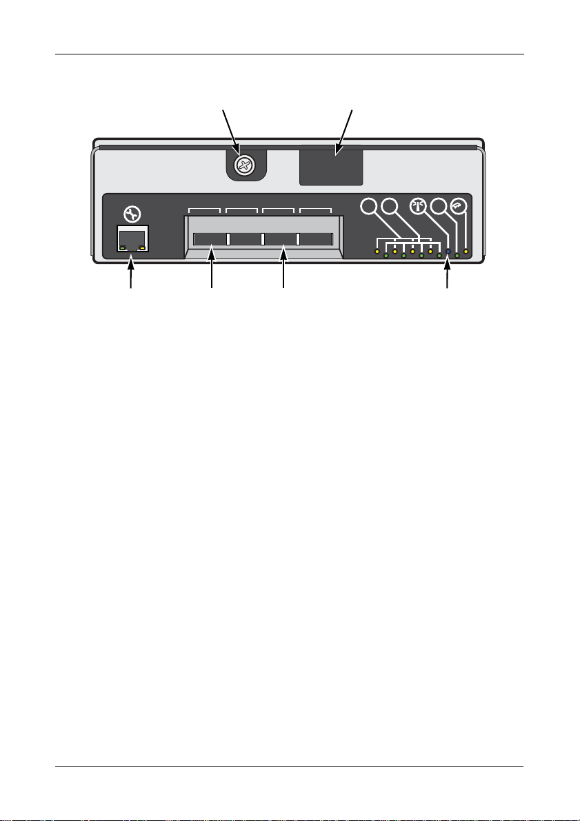
Figure 14.I/O Module
Lock bar tabThumbscrew
Locator LEDSAS cables attach hereNot used
Replacing an I/O Module
HOST 1 HOST 2 HOST 3 HOST 4
LINK
!
!
On the new I/O Module:
1. Press the I/O Module completely into the enclosure.
2. Press the tab on the lock bar and toward the I/O Module until it locks in
place.
3. Tighten the thumbscrew.
4. Attach the SAS cables.
After a few moments, the J930s unit detects the replacement I/O Module.
The cooling fans resume normal speed and the alarm goes silent.
This completes the I/O Module replacement.
47
Page 52

VTrak J930s Product Manual
!
!
LINK
HOST 1 HOST 2 HOST 3 HOST 4
!
!
LINK
HOST 1 HOST 2 HOST 3 HOST 4
!
AC DC
!
AC DC
Power switch Power switch
Shutting Down and Restarting the VTrak
• Shutdown Sequence – Single Unit (page 48)
• Shutdown Sequence – Multiple Units (page 48)
• Power-up Sequence – Single Unit (page 49)
• Power-up Sequence – Multiple Units (page 49)
Shutdown Sequence – Single Unit
To shut down a single VTrak J930s unit:
1. Power down the VTrak RAID subsystem.
2. Turn OFF the switches on both power supplies on the J930s unit.
Shutdown Sequence – Multiple Units
To shut down multiple VTrak J930s units:
1. Power down the VTrak RAID subsystem.
2. Turn OFF the switches on both PCMs of the first J930s unit in the cascade.
3. Turn OFF the switches on both PCMs of the last J930s unit in the cascade.
Figure 15.Power switches
Wait at least 30 seconds after shutdown before you restart the
J930s unit.
48
Important
Page 53

Shutting Down and Restarting the VTrak
!
!
LINK
HOST 1HOST 2HOST 3HOST 4
!
!
LINK
HOST 1 HOST 2 HOST 3 HOST 4
!
AC DC
!
AC DC
!
!
LINK
HOST 1HOST 2HOST 3HOST 4
!
!
LINK
HOST 1 HOST 2 HOST 3 HOST 4
!
AC DC
!
AC DC
last J930s
first J930s
VTrak RAID
subsystem
Step 1.
Step 2.
Step 3.
Power-up Sequence – Single Unit
To power up a single VTrak J930s unit:
1. Switch ON both PCMs on the J930s unit.
2. Wait at least one minute and then power up the VTrak RAID subsystem.
Power-up Sequence – Multiple Units
To power up the multiple VTrak J930s units:
1. Switch ON both PCMs of the last J930s unit in the cascade.
See Figure 16.
2. Wait at least one minute and then switch ON both PCMs of the first J930s
unit in the cascade.
3. Wait at least one minute and then power up the VTrak RAID subsystem.
Figure 16.Power-up sequence for cascaded units
49
Page 54

VTrak J930s Product Manual
50
Page 55

Chapter 4: Support
This chapter covers the following topics:
• Frequently Asked Questions (below)
• Contacting Technical Support (page 52)
• Limited Warranty (page 57)
• Returning the Product for Repair (page 59)
Frequently Asked Questions
What kind of physical drives can I use with VTrak?
VTrak J930s supports:
• 3.5-inch and 2.5-inch form factor
• SAS drives, 6 Gb/s and 3 Gb/s
• Hard disk drives (HDDs) and solid state drives (SSDs)
• Supports any mix of SAS and SATA drives simultaneously in the same
enclosure
For a list of compatible drives, go to PROMISE support:
http://www.promise.com/support/.
VTrak J930s does not support Parallel ATA (PATA) disk drives.
How can I tell when the VTrak has fully booted?
When boot-up is finished and the J930s unit is functioning normally:
• The Power LED shows green.
• Other LEDs are dark.
See “Front Panel LEDs” on page 33 for more information.
Can I hot-swap a failed drive with a new one?
Yes. Physical drives are hot-swappable on the J930s unit.
Can I connect the VTrak J930s to a SAS HBA card in my host PC?
Yes. The J930s unit can be connected to a SAS HBA card in a host PC or
server, without using a RAID subsystem.
Why is there an Ethernet connector on each I/O module?
The Ethernet network connector (right) is not used in the
field. It is used for de-bugging only.
51
Page 56

VTrak J-930s Product Manual
Contacting Technical Support
PROMISE Technical Support provides several support options for PROMISE
users to access information and updates. We encourage you to use one of our
electronic services, which provide product information updates for the most
efficient service and support.
PROMISE E-Support: https://support.promise.com
PROMISE web site: http://www.promise.com/apple/
When you contact us, please have the following information available:
• Product model and serial number
• BIOS, firmware, and driver version numbers
• A description of the problem / situation
• System configuration information, including: motherboard and CPU type,
hard drive models, SAS/SATA/ATA/ATAPI drives & devices, and other
controllers.
United States
580 Cottonwood Drive
Milpitas, Ca 95035, USA
Apple Pre-Sales: 1 408 228-1400 Option 2
Apple Support Phone T oll Free: 1-800-888-0245 Option 8
Fax: 1 408 228-1097
Apple Sales Email: apple@promise.com
Technical Support (E-Support): https://support.promise.com
Web site: http://www.promise.com/apple/
Australia
Apple Pre-Sales Toll Free: 1800-149-746
Apple Support Phone Toll Free: 1800-149-746
Apple Sales Email: apple@promise.com
Technical Support (E-Support): https://support.promise.com
Web site: http://www.promise.com/apple/
52
Page 57

EMEA
Netherlands
Science Park Eindhoven 5228
5692 EG Son, The Netherlands
Apple Pre-Sales Toll Free Phone (0830 to 1700): 0800-917-027
Apple Support Phone (0830 to 1700) Toll Free : 0800-917-027
Apple Support Phone (After Hours, English only) Toll Free: 0800-917-027
Fax: +31 (0) 40-256-9463
Apple Sales Email: apple@promise.com
Technical Support (E-Support): https://support.promise.com
Web site: http://www.promise.com/apple/
Austria
Apple Pre-Sales Toll Free Phone (0830 to 1700): 0800-295-731
Apple Support Toll Free Phone (0830 to 1700): 0800-295-731
Apple Support Toll Free Phone (After Hours, English only): 0800-295-731
Apple Sales Email: apple@promise.com
Technical Support (E-Support): https://support.promise.com
Web site: http://www.promise.com/apple/
Chapter 4: Support
France
Apple Pre-Sales Toll Free Phone (0830 to 1700): 0800-917-027
Apple Support Toll Free Phone (0830 to 1700): 0800-917-027
Apple Support Toll Free Phone (After Hours, English only): 0800-917-027
Apple Sales Email: apple@promise.com
Technical Support (E-Support): https://support.promise.com
Web site: http://www.promise.com/apple/
Germany
Europaplatz 9
44269 Dortmund, Germany
Apple Pre-Sales Toll Free Phone (0830 to 1700): 0800-187-3557
Apple Support Toll Free Phone (0830 to 1700): 0800-187-3557
Apple Support Toll Free Phone (After Hours, English only): 0800-187-3557
Apple Sales Email: apple@promise.com
Technical Support (E-Support): https://support.promise.com
Web site: http://www.promise.com/apple/
53
Page 58

VTrak J-930s Product Manual
Sweden
Apple Pre-Sales Toll Free Phone (0830 to 1700): 02 0-797-720
Apple Support Toll Free Phone (0830 to 1700 ): 020-797-720
Apple Support Toll Free Phone (After Hours, English only): 020-797-720
Apple Sales Email: apple@promise.com
Technical Support (E-Support): https://support.promise.com
Web site: http://www.promise.com/apple/
Switzerland ITF
Apple Pre-Sales Toll Free Phone (0830 to 1700): 0800-562-898
Apple Support Toll Free Phone (0830 to 1700): 0800-562-898
Apple Support Toll Free Phone (After Hours, English only): 0800-562-898
Apple Sales Email: apple@promise.com
Technical Support (E-Support): https://support.promise.com
Web site: http://www.promise.com/apple/
Norway ITF
Apple Pre-Sales Toll Free Phone (0830 to 1700): 0800-15406
Apple Support Toll Free Phone (0830 to 1700): 0800-15406
Apple Support Toll Free Phone (After Hours, English only): 080 0-15406
Apple Sales Email: apple@promise.com
Technical Support (E-Support): https://support.promise.com
Web site: http://www.promise.com/apple/
Belgium
Apple Pre-Sales Toll Free Phone (0830 to 1700): 0800-71915
Apple Support Toll Free Phone (0830 to 1700): 0800-71915
Apple Support Toll Free Phone (After Hours, English only): 080 0-71915
Apple Sales Email: apple@promise.com
Technical Support (E-Support): https://support.promise.com
Web site: http://www.promise.com/apple/
54
Page 59

Luxembourg
Apple Pre-Sales Toll Free Phone (0830 to 1700): 0800-26425
Apple Support Toll Free Phone (0830 to 1700): 0800-26425
Apple Support Toll Free Phone (After Hours, English only): 080 0-26425
Apple Sales Email: apple@promise.com
Technical Support (E-Support): https://support.promise.com
Web site: http://www.promise.com/apple/
United Kingdom
Apple Pre-Sales Toll Free Phone (0830 to 1700): 0800-587-1068
Apple Support Toll Free Phone (0830 to 1700): 0800-587-1068
Apple Support Toll Free Phone (After Hours, English only): 0800-587-1068
Apple Sales Email: apple@promise.com
Technical Support (E-Support): https://support.promise.com
Web site: http://www.promise.com/apple/
Taiwan
Apple Pre-Sales Toll Free (24x7 English only): 008-0113-6030
Apple Support Phone T oll Free (24x7 English only): 008-0113-6030
Apple Sales Email: apple@promise.com
Technical Support (E-Support): https://support.promise.com
Web site: http://www.promise.com/apple/
Chapter 4: Support
China
Room 1108, West Wing, Shi Chuang Plaza, 22 Information Road
Shangdi IT Park, Hai Dian District, Beijing 100085
Apple Pre-Sales Toll Free: 86-10-8857-8085/8095
Apple Support Phone T oll Free: 86-10-8857-8085/8095
Fax: 86-10-8857-8015
Apple Sales Email: apple@promise.com
Technical Support (E-Support): https://support.promise.com
Web site: http://www.promise.com/apple/
55
Page 60

VTrak J-930s Product Manual
Korea
Apple Pre-Sales Toll Free (24x7 English only): 00798-14-800-7784
Apple Support Phone T oll Free (24x7 English only): 00798-14-800-7784
Apple Sales Email: apple@promise.com
Technical Support (E-Support): https://support.promise.com
Web site: http://www.promise.com/apple/
Hong Kong
Apple Pre-Sales Toll Free Phone (24x7 English only): 800-933-480
Apple Support Toll Free Phone (24x7 English only): 800-933-480
Apple Sales Email: apple@promise.com
Technical Support (E-Support): https://support.promise.com
Web site: http://www.promise.com/apple/
Singapore
Apple Pre-Sales Toll Free Phone (24x7 English only): 800-492-2153
Apple Support Toll Free Phone (24x7 English only): 800-492-2153
Apple Sales Email: apple@promise.com
Technical Support (E-Support): https://support.promise.com
Web site: http://www.promise.com/apple/
Japan
3F, Mura Matsu Bldg, 3-8-5, Hongo Bunkyo-ku
Tokyo 113-0033, Japan
Apple Pre-Sales Toll Free Phone (24x7 Englis h only): 0066-3384-9021
Apple Support Toll Free Phone (24x7 English only): 0066-3384-9021
Apple Sales Email: apple@promise.com
Technical Support (E-Support): https://support.promise.com
Web site: http://www.promise.com/apple/
56
Page 61

Chapter 4: Support
Limited Warranty
PROMISE Technology, Inc. (“PROMISE”) warrants that this product, from the
time of the delivery of the product to the original end user:
a) all components for a period of three (3) years;
b) will conform to PROMISE’s specifications;
c) will be free from defects in material and workmanship under normal use
and service.
This warranty:
a) applies only to products which are new and in cartons on the date of
purchase;
b) is not transferable;
c) is valid only when accompanied by a copy of the original purchase
invoice.
d) Is not valid on spare parts.
This warranty shall not apply to defects resulting from:
a) improper or inadequate maintenance, or unauthorized modification(s),
performed by the end user;
b) operation outside the environmental specifications for the product;
c) accident, misuse, negligence, misapplication, abuse, natural or
personal disaster, or maintenance by anyone other than a PROMISE or
a PROMISE-authorized service center.
Disclaimer of other warranties
This warranty covers only parts and labor, and excludes coverage on software
items as expressly set above.
Except as expressly set forth above, PROMISE DISCLAIMS any warranties,
expressed or implied, by statute or otherwise, regarding the product, including,
without limitation, any warranties for fitness for any purpose, quality,
merchantability, non-infringement, or otherwise. PROMISE makes no warranty or
representation concerning the suitability of any product for use with any other
item. You assu me full responsibility for selecting products and for ensuring that
the products selected are compatible and appropriate for use with other goods
with which they will be used.
PROMISE DOES NOT WARRANT that any product is free from errors or that it
will interface without problems with your computer system. It is your responsibility
57
Page 62

VTrak J-930s Product Manual
to back up or otherwise save important data before installing any product and
continue to back up your important data regularly.
No other document, statement or representation may be relied on to vary the
terms of this limited warranty.
PROMISE’s sole responsibility with respect to any product is to do one of the
following:
a) replace the product with a conforming unit of the same or superior
product;
b) repair the product.
PROMISE shall not be liable for the cost of procuring substitute goods, services,
lost profits, unrealized savings, equipment damage, costs of recovering,
reprogramming, or reproducing of programs or data stored in or used with the
products, or for any other general, special, consequential, indirect, incidental, or
punitive damages, whether in contract, tort, or otherwise, notwithstanding the
failure of the essential purpose of the foregoing remedy and regardless of
whether PROMISE has been advised of the possibility of such damages.
PROMISE is not an insurer. If you desire insurance against such damage, you
must obtain insurance from another party.
Some states do not allow the exclusion or limitation of incidental or consequential
damages for consumer products, so the above limitation may not apply to you.
This warranty gives specific legal rights, and you may also have other rights that
vary from state to state. This limited warranty is governed by the State of
California.
Your Responsibilities
You are responsible for determining whether the product is appropriate for your
use and will interface with your equipment without malfunction or damage. You
are also responsible for backing up your data before installing any product and
for regularly backing up your data after installing the product. PROMISE is not
liable for any damage to equipment or data loss resulting from the use of any
product.
58
Page 63

Chapter 4: Support
Returning the Product for Repair
If you suspect a product is not working properly, or if you have any questions
about your product, contact our Technical Support Staff through one of our
Technical Services, making sure to provide the following information:
• Product model and serial number (required)
• Return shipping address
• Daytime phone number
• Description of the problem
• Copy of the original purchase invoice
The technician will assist you in determining whether the product requires repair.
If the product needs repair, the Technical Support Department will issue an RMA
(Return Merchandise Authorization) number.
Important
Obtain an RMA number from Technical Support before you return
the product and write the RMA number on the label. The RMA
number is essential for tracking your product and providing the
proper service.
Return ONLY the specific product covered by the warranty. Do not ship cables,
manuals, diskettes, etc.
USA and Canada: PROMISE Technology, Inc.
Customer Service Dept.
Attn.: RMA # ______
47654 Kato Road
Fremont, CA 94538
Other Countries: Return the product to your dealer
or retailer.
Contact them for instructions
before shipping the product.
You must follow the packaging guidelines for returning products:
• Use the original shipping carton and packaging
• Include a summary of the product’s problem(s)
• Write an attention line on the box with the RMA number
• Include a copy of your proof of purchase
59
Page 64

VTrak J-930s Product Manual
You are responsib le for the cost of insurance and shipment of the product to
PROMISE. Note that damage incurred due to improper transport or packaging is
not covered under the Limited Warranty.
When repairing returned product(s), PROMISE may replace defective parts with
new or reconditioned parts, or replace the entire unit with a new or reconditioned
unit. In the event of a replacement, the replacement unit will be under warranty
for the remainder of the original warranty term from purchase date, or 30 days,
whichever is longer.
PROMISE will pay for standard return shipping charges only . You will be required
to pay for any additional shipping options, such as express shipping.
60
Page 65

Index
A
about this manual 1
B
bezel, install 14
C
cable
management kit
power 28
SAS SFF-8088 9, 26, 27
CE statement 7
CLI 31
clips, power cable 28
command line interface 31
connection
network
power 28
SAS cable 25–28
51
15–17
D
data cable connections
basic DAS
cascading DAS 26
redundant cascading DAS 27
disk drives, see physical drives
drive bay doors
drive carriers
2.5 inch
3.5 inch 18
install 22
LED 34, 42
drive slot numbering 41
25
22, 40
20
E
enclosure
install into rack
slide out of rack 38
10–13
ESD Warning 9
Ethernet connector 51
F
FCC statement 7
Features and Benefits 4
front panel LEDs 33
H
host PC with SAS HBA card 2, 51
I
I/O module
LEDs
34
locator LED 46
replace 46
install
bezel
14
cable management kit 15–17
drive carriers 22
physical drives 18–??
L
LEDs
AC power
DC power 37
drive activity 33
drive bay doors 33, 40
drive carrier 34, 42
enclosure fault 33
front panel 33
I/O module locator 46
I/O module status 34
PCM locator 44
PCM status 37
power 33
SAS ports 34, 36
37
61
Page 66

VTrak J930s Product Manual
locate
drive carrier
enclosure 34
I/O module 35
PCM 37
34
O
overview of VTrak J930s 2
P
PCM
LEDs
37
locator LED 44
power cable 28
power switches 48
replace 44
physical drives
hot-swappable
install 18–24
replace 38–43
supported 5, 18, 51
power
cable clips
connection 28
power-up sequence 29, 49
51
28
replace
I/O module
PCM 44
physical drives 38–43
returning product for repair 59
46
S
SAS
cable
25
cable connections 25–28
HBA card 2, 51
SFF-8088 cable 9, 26, 27
shutdown sequence 48
T
Technical Support, contact 52
V
VCC statement 7
VTrak
warranty
VTrak J930s
overview
rack-mount 11
57
2
R
RAID subsystem
basic DAS
cascading DAS 26
defined 1
power-up sequence 29, 49
redundant cascading DAS 27
shutdown sequence 48
regulatory statements 7
25
W
warranty 57
WebPAM PROe
drive slot numbering
in place of CLI 31
locate I/O module 46
locate PCM 44
locate physical drive 42
VTrak RAID subsystem 1
62
41
 Loading...