

Page 1
Page 2

VTrak 830s, J630s Quick Start Guide
Contents
English . . . . . . . . . . . . . . . . . . . . . . . . . . . . . . . . . . . . . . . . . . . . . . .3
Deutsch . . . . . . . . . . . . . . . . . . . . . . . . . . . . . . . . . . . . . . . . . . . . .22
Français . . . . . . . . . . . . . . . . . . . . . . . . . . . . . . . . . . . . . . . . . . . . .46
Italiano . . . . . . . . . . . . . . . . . . . . . . . . . . . . . . . . . . . . . . . . . . . . . .66
Español . . . . . . . . . . . . . . . . . . . . . . . . . . . . . . . . . . . . . . . . . . . . . .86
Pусский язык . . . . . . . . . . . . . . . . . . . . . . . . . . . . . . . . . . . . . . . .106
日本語 . . . . . . . . . . . . . . . . . . . . . . . . . . . . . . . . . . . . . . . . . . . . . .128
繁體中文 . . . . . . . . . . . . . . . . . . . . . . . . . . . . . . . . . . . . . . . . . . . .148
简体中文 . . . . . . . . . . . . . . . . . . . . . . . . . . . . . . . . . . . . . . . . . . . .167
한국어 . . . . . . . . . . . . . . . . . . . . . . . . . . . . . . . . . . . . . . . . . . . . . .186
2
Page 3
VTrak Task List
• Task 1: Unpacking the VTrak (below)
• Task 2: Mounting the VTrak Unit in a Rack (page 5)
• Task 3: Installing Disk Drives (page 8)
• Task 4: Making Data Connections (page 13)
• Task 5: Setting Up Serial Cable Connections (page 17)
• Task 6: Connecting the Power (page 18)
• Task 7: Setting Up the CLI Connection (page 19)
• Frequently Asked Questions (page 20)
• Contacting Technical Support (page 21)
Thank you for purchasing a Promise VTrak J830s or J630s external disk
subsystem.
Please read through these instructions completely before you begin. You might
need additional items to complete your installation.
Task 1: Unpacking the VTrak
The VTrak J830s or J630s box contains the following items:
•VTrak Unit
• Quick Start Guide
• RJ11-to-DB9 serial data cables
(2)
• 1.0m (3.3 ft) SFF-8088 4X to 4X
external SAS cables (2)
• Screws for disk drives
(J830s: 106, including 10 spares)
(J630s: 70, including 6 spares)
• Left and right mounting rails
• 1.5m (4.9 ft) Power cords (2)
• CD with Product Manual and Quick
Start Guide
Warning
The electronic components within the VTrak are sensitive to
damage from Electro-Static Discharge (ESD). Observe
appropriate precautions at all times when handling the VTrak or its
subassemblies.
Caution
VTrak supports disk drive hot-swapping. To avoid hand contact
with an electrical hazard, do not remove more than one drive
carrier a time.
3
Page 4
Task 1: Unpacking the VTrak
Notices
Warning to User: This is Class A ITE product which might cause
radio frequency interference if it is used in a residential
environment. In such case, the user would be requested to adopt
certain appropriate measures.
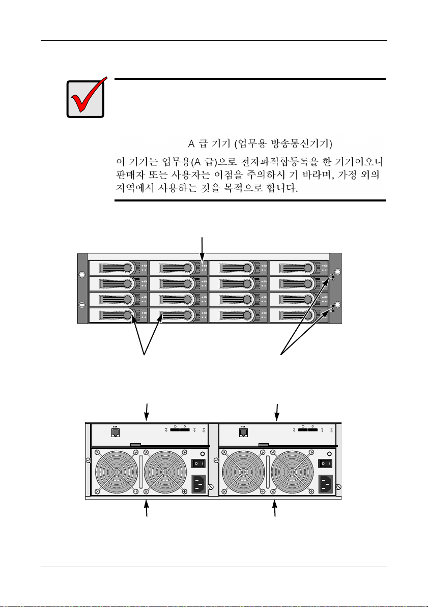
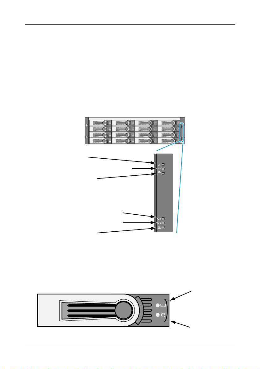
Figure 1. VTrak J630s front view. The J830s is similar
Drive Carrier LEDs
Drive Carriers
Power and Status LEDs
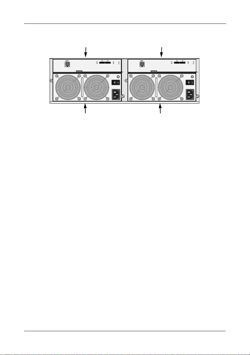
Figure 2. VTrak J630s rear view. The J830s is similar
I/O module 1
115200 8 N 1 115200 8 N 1
Power Supply 1
4
I/O module 2
Power Supply 2
Page 5
VTrak J830s, J630s Quick Start Guide
Task 2: Mounting the VTrak Unit in a Rack
Cautions
• At least two persons are required to safely lift, place, and
attach the VTrak unit into a rack system.
• Do not lift or move the VTrak unit by the handles, power
supplies or the controller units. Hold the subsystem itself.
• Do not install the VTrak unit into a rack without rails to support
the subsystem.
• Only a qualified technician who is familiar with the installation
procedure should mount and install the VTrak unit.
• Be sure all switches are OFF before installing the VTrak unit
or exchanging components.
• Mount the rails to the rack using the appropriate screws and
flange nuts, fully tightened, at each end of the rail.
• Do not load the rails unless they are installed with screws as
instructed.
• The rails that ship with the Promise VTrak unit are designed
to safely support that Promise VTrak unit when properly
installed. Additional loading on the rails is at the customer’s
risk.
• Promise Technology , Inc. cannot guarantee that the mounting
rails will support your Promise VTrak unit unless you install
them as instructed.
Note
To lighten the VTrak enclosure, remove the power supplies.
Replace the power supplies after the VTrak unit is mounted in your
rack.
The J830s and J630s subsystems install to the rack using the supplied mounting
rails. You can also use your existing rails.
5
Page 6
Task 2: Mounting the VTrak Unit in a Rack
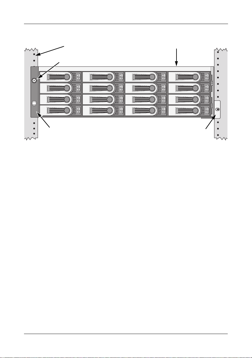
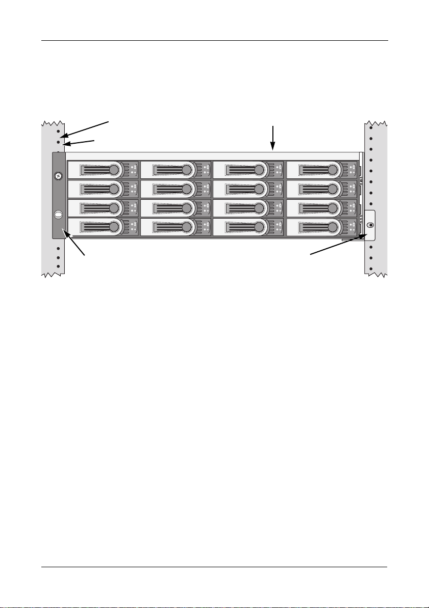
Figure 3. VTrak J630s mounted in a rack with the supplied rails
Vertical Rack Post VTrak J630s
Attaching screw & flange nut
Upper hole only
Handles mount
outside the rack post
To install the VTrak subsystem into a rack with the supplied mounting rails:
Mounting rails (included)
mount outside the rack post
1. Check the fit of the mounting rails in your rack system. See page 7, Figure 4.
2. Adjust the length of the mounting rails as needed.
The rear rail slides inside the front rail. The rail halves are riveted together
and use no adjustment screws.
3. Attach the mounting rail assemblies to the outside of the rack posts, using
the attaching screws and flange nuts from your rack system.
Be sure the front rail support is on the bottom facing inward.
The alignment pins fit into the rack holes above and below the attaching
screws.
Use the attaching screws and flange nuts from your rack system. Tighten the
screws and flange nuts according to your rack system instructions.
4. Place the VTrak subsystem onto the rails.
5. Secure the VTrak subsystem to the rack.
One screw each side. Use the attaching screws and flange nuts from your
rack system. Tighten the screws and flange nuts according to your rack
system instructions.
6
Page 7
VTrak J830s, J630s Quick Start Guide
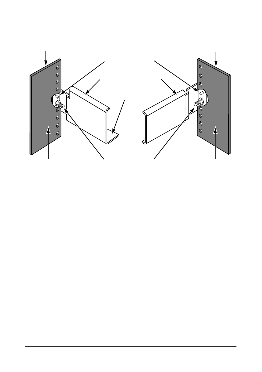
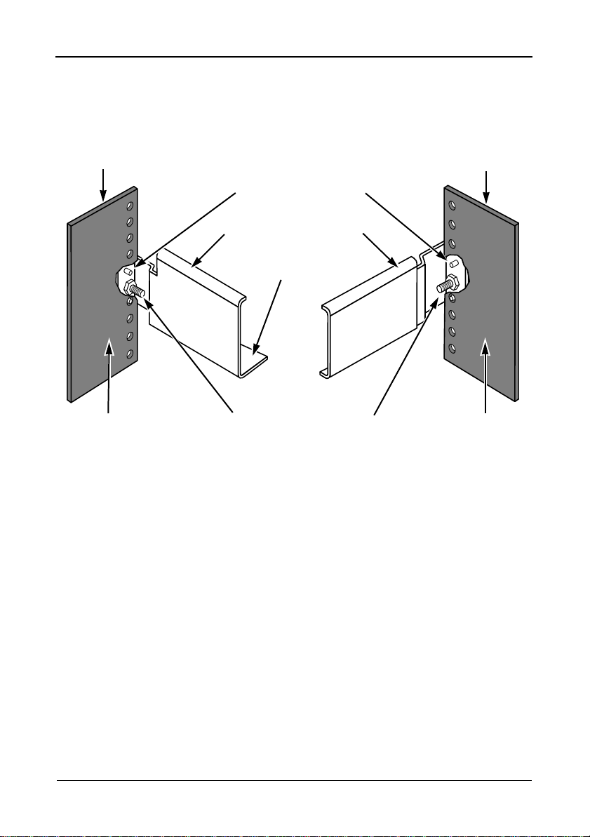
Figure 4. Rack mount assembly diagram
Rack front post
Inside of post
Note that only the front rail has a support for the subsystem.
Alignment pins
two on each flange
Front rail
Rear rail
Support for
subsystem
Rail attaching screws
(not included)
Rack rear post
Inside of post
7
Page 8
Task 3: Installing Disk Drives
Task 3: Installing Disk Drives
You can populate the VTrak enclosure with SAS or SATA disk drives. See the
Compatibility List on the Promise Website for a list of qualified disk drives.
For optimal performance, install disk drives of the same model and capacity.
Drive Slot Numbering
You can install any qualified disk drive into any slot in the enclosure. The
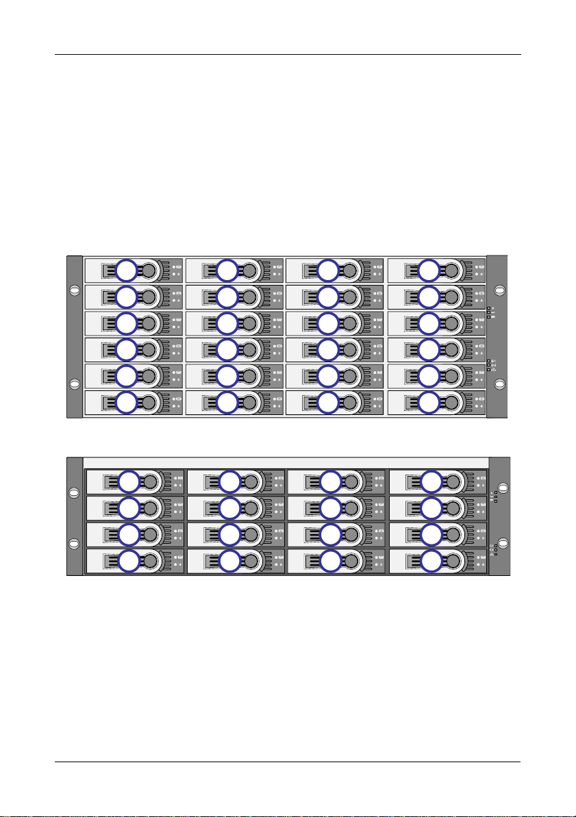
diagrams below show how VTrak’s drive slots are numbered.
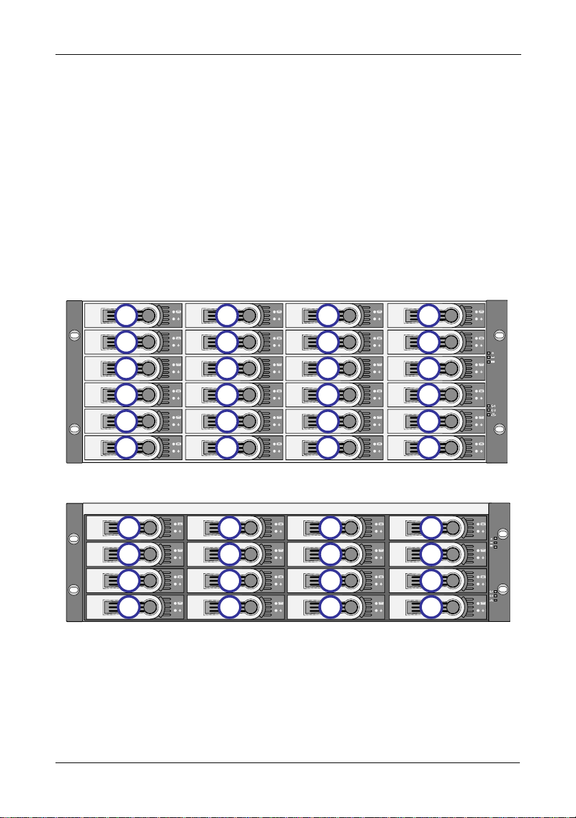
Figure 5. VTrak J830s drive slot numbering
1
5
9
13
17
21
Figure 6. VTrak J630s drive slot numbering
1
5
9
13
Install all of the drive carriers into the VTrak enclosure to ensure proper airflow,
even if you do not populate all the carriers with disk drives.
2
7
10
14
18
22
10
14
3
7
11
15
19
23
2
7
3
7
11
15
4
8
12
16
20
24
4
8
12
16
8
Page 9

VTrak J830s, J630s Quick Start Guide
Installing 3.5-inch Disk Drives
Important
• If your VTrak has two I/O modules and you are installing
SA TA disk drives, an AAMUX adapter is required so that both
modules can access the SA TA disk drive. Obtain AAMUX
adapters from Promise Technology, Inc.
• Proper installation ensures adequate grounding and
minimizes vibration. Always install the disk drives using all
four screws.
To install your 3.5-inch disk drives:
1. Remove a disk drive carrier.
2. Carefully lay the drive into the drive carrier at the front, so that the screw
holes on the sides line up.
If you are installing a AAMUX adapters and SATA disk drives:
First attach the adapter to the drive. Then install the mounting screws.
See page 10, Figure 7.
3. Insert the screws through the holes in the sides of the drive carrier and into
the disk drive. See page 10, Figures 7 and 8.
• For the disk drive, install only the screws supplied with the VTrak.
• For the adapter, install only the screws supplied with the adapter.
• Install four screws per drive.
• Install two screws per adapter.
• Snug each screw. Be careful not to over tighten.
4. Reinstall the drive carrier into the VTrak enclosure.
5. Repeat steps 2 through 4 until all of your disk drives are installed.
Caution
VTrak supports disk drive hot-swapping. To avoid hand contact
with an electrical hazard, do not remove more than one drive
carrier a time.
9
Page 10
Task 3: Installing Disk Drives
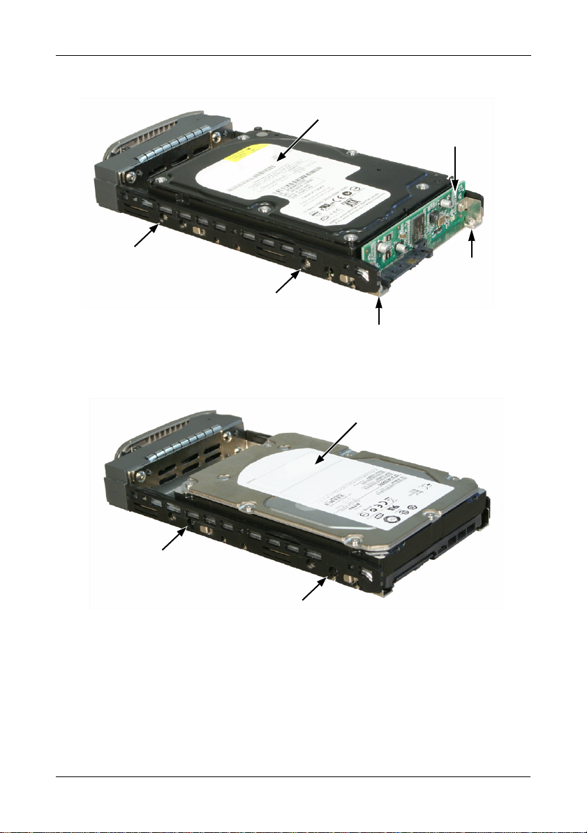
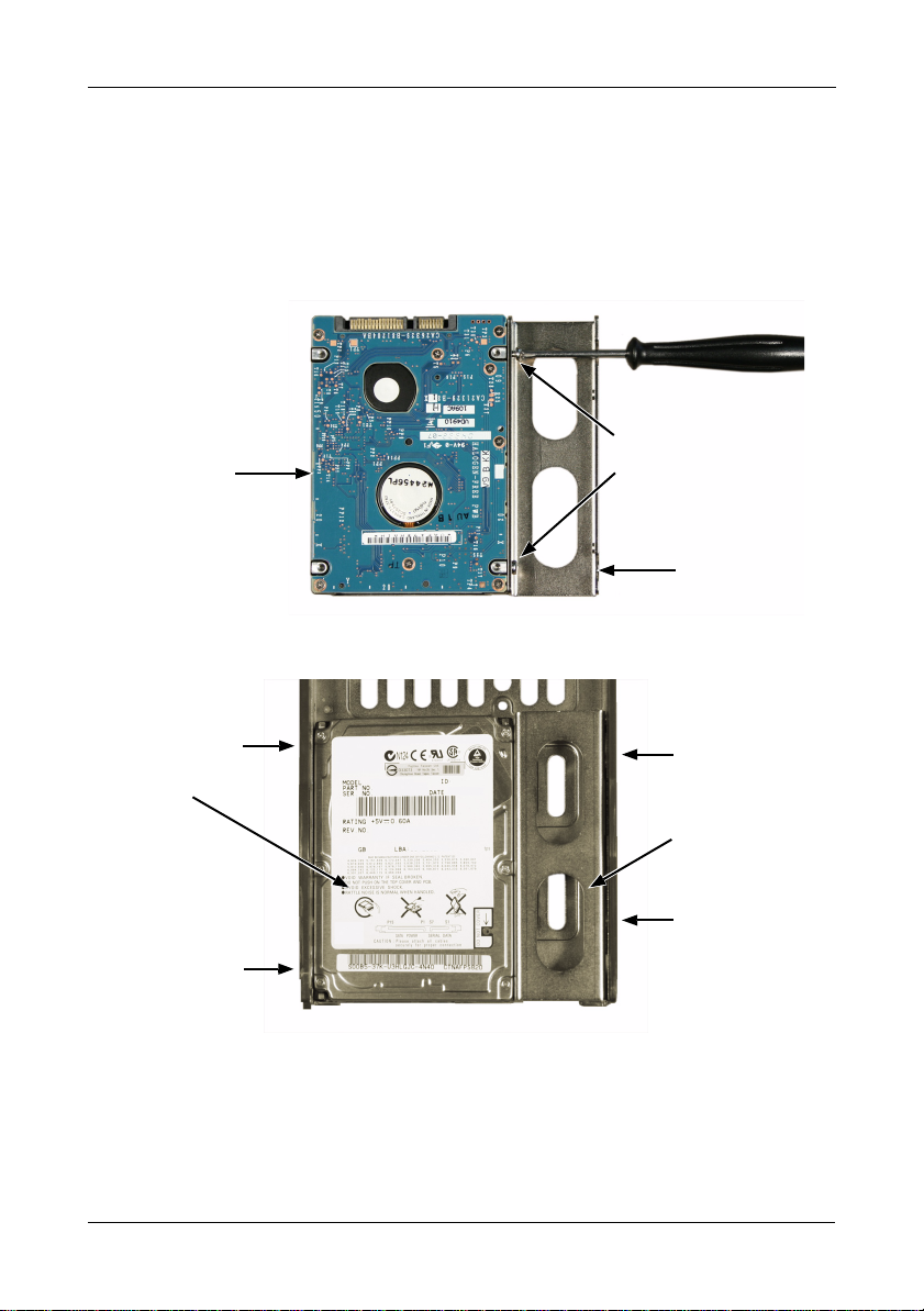
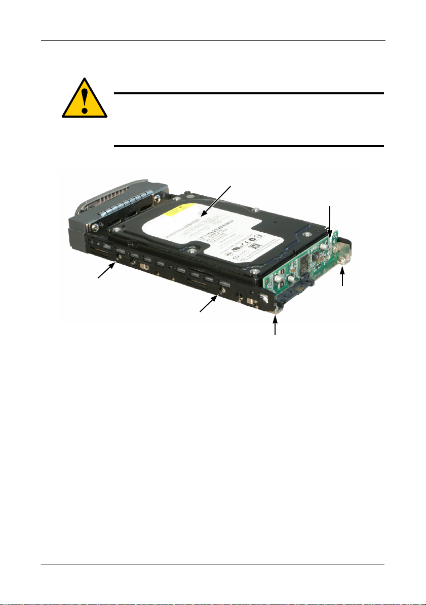
Figure 7. Drive carrier with 3.5-inch SATA disk drive and adapter
SATA Disk Drive
AAMUX adapter
Disk Drive
mounting screw
Disk Drive
mounting screw
adapter
mounting
screw
Figure 8. Drive carrier with 3.5-inch SAS disk drive
SAS Disk Drive
adapter
mounting
screw
Disk Drive
mounting screw
Disk Drive
mounting screw
10
Page 11

VTrak J830s, J630s Quick Start Guide
Installing 2.5-inch Disk Drives
• Always use mounting brackets to install 2.5-inch disk drives.
Never install disk drives by inserting screws through the
bottom of the drive carrier. Obtain mounting brackets and
screws from Promise Technology, Inc.
• Hold 2.5-inch disk drives by the edge to prevent damage to
the drive.
• VTrak supports disk drive hot-swapping. To avoid hand
contact with an electrical hazard, do not remove more than
one drive carrier a time.
• If your VTrak has two I/O modules and you are installing
SA TA disk drives, an AAMUX adapter is required so that both
modules can access the SA TA disk drive. Obtain AAMUX
adapters from Promise Technology, Inc.
• Proper installation ensures adequate grounding and
minimizes vibration. Always install the disk drives using all
four screws.
Cautions
Important
To install your 2.5-inch disk drives:
1. Attach a bracket to the disk drive. See page 12, Figure 9.
• Install only the screws supplied with the bracket.
• Install two screws per bracket.
• Snug each screw. Be careful not to over tighten.
2. Remove a disk drive carrier.
3. Carefully lay the drive into the drive carrier at the front, so that the screw
holes on the sides line up.
If you are installing a AAMUX adapters and SATA disk drives:
First attach the adapter to the drive. Then install the mounting screws.
4. Insert the screws through the holes in the sides of the drive carrier and into
the disk drive. See page 12, Figure 10.
• For the disk drive, install only the screws supplied with the VTrak.
• For the bracket, install only the screws supplied with the bracket.
• For the adapter, install only the screws supplied with the adapter.
11
Page 12
Task 3: Installing Disk Drives
D
m
D
m
D
• Install two screws per drive, two screws per bracket, and two screws per
adapter.
• Snug each screw. Be careful not to over tighten.
5. Reinstall the drive carrier into the VTrak enclosure.
6. Repeat steps 2 through 5 until all of your disk drives are installed.
Figure 9. 2.5-inch disk drive and mounting bracket
Disk drive
Disk drive
mounting screws
Mounting
bracket
Figure 10.Drive carrier mounting screw locations
isk drive
ounting screw
Bracket
mounting screw
isk drive
Mounting
bracket
Bracket
mounting screw
isk drive
ounting screw
Note: The bracket screws are larger than disk drive screws.
12
Page 13
VTrak J830s, J630s Quick Start Guide
rt
Task 4: Making Data Connections
You can configure your VTrak subsystem as:
• Basic Direct Attached Storage (DAS) Connection (below)
• Cascading DAS Connection (page 14)
• Redundant Cascading DAS Connection (page 15)
Basic DAS Connection
To setup a basic DAS connection:
• You must have a SAS HBA card in the Host PC or server.
• Connect the SAS HBA card in the Host PC to the SAS IN port (with the circle
icon) on the VTrak. See Figure 11.
• Use the SFF-8088 4X to 4X external SAS cable supplied with the VTrak.
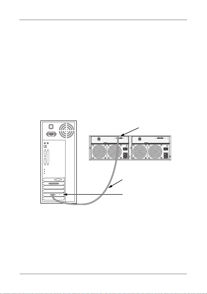
Figure 11. A basic DAS connection
SAS IN circle po
115200 8 N 1 115200 8 N 1
VTrak J630s
SFF-8088 external
4X to 4X SAS cable
SAS HBA Card
Host PC or Server
The diagram above shows the VTrak J630s. A connection with the J830s is
exactly the same.
This completes data and management connections. Go to “Task 5: Setting Up
Serial Cable Connections” on page 17.
13
Page 14
Task 4: Making Data Connections
Cascading DAS Connection
To setup a cascading DAS connection:
1. Connect the SAS HBA card in the Host PC to the SAS IN port (with the circle
icon) on the first VTrak.
See Figure 12. Use a SFF-8088 4X to 4X external SAS cable (supplied with
the VTrak).
2. Connect the SAS OUT port (with the diamond icon) on the same I/O module
of the first VTrak to the SAS IN port (with the circle icon) on the second
VTrak.
Be sure to connect circle icon to diamond icon or vice versa.
You can cascade up to four VTrak units in this manner.
You can mix J830s and J630s units as well as J610s and J310s units in the
same cascade. Note that Jx10s are 3Gb units and might reduce data
throughput.
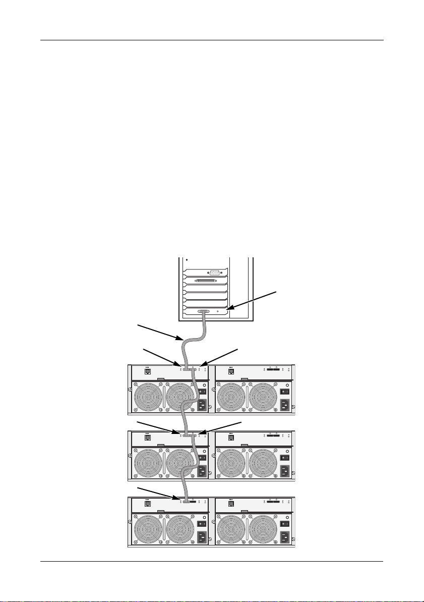
Figure 12. A cascaded DAS connection
SAS HBA Card
SFF-8088 external
4X to 4X SAS cable
SAS IN circle port
SAS IN circle port
SAS IN circle port
Host PC or Server
SAS OUT diamond port
115200 8 N 1 115200 8 N 1
VTrak J630s
SAS OUT diamond port
115200 8 N 1 115200 8 N 1
VTrak J630s
115200 8 N 1 115200 8 N 1
VTrak J630s
14
Page 15

VTrak J830s, J630s Quick Start Guide
The diagram on page 14 shows the VTrak J630s. Connections with the J830s are
exactly the same.
This completes data and management connections. Go to “Task 5: Setting Up
Serial Cable Connections” on page 17.
Redundant Cascading DAS Connection
To setup a redundant cascading DAS connection:
1. Connect the SAS HBA card in the first Host PC to the SAS IN port (with the
circle icon) on the first VTrak.
See page 16, Figure 13. Use a SFF-8088 4X to 4X external SAS cable
(supplied with the VTrak).
2. Connect the SAS OUT port (with the diamond icon) on the same I/O module
of the first VTrak to the SAS IN port (with the circle icon) on the second
VTrak.
3. Connect the SAS HBA card in the second Host PC to the SAS IN port (with
the circle icon) to the other I/O module on the first VTrak.
4. Connect the SAS OUT port (with the diamond icon) on the same I/O module
of the first VTrak to the SAS IN port (with the circle icon) of the other I/O
module on the second VTrak.
5. Connect the remaining VTraks in the same manner.
Be sure to connect circle icon to diamond icon or vice versa.
Do not cross-connect the I/O modules. Maintain a separate cascade
configuration from each Host PC or Server to the last VTrak. See page 16,
Figure 13.
You can cascade up to four VTrak units in this manner.
You can mix J830s and J630s units as well as J610s and J310s units in the
same cascade. Note that Jx10s are 3Gb units and might reduce data
throughput.
15
Page 16

Task 4: Making Data Connections
Figure 13.A redundant cascading DAS connection
SAS HBA
Cards
SFF-8088 external
4X to 4X SAS cables
SAS IN circle port
115200 8 N 1 115200 8 N 1
SAS OUT
diamond port
SAS OUT
SAS IN circle port
115200 8 N 1 115200 8 N 1
VTrak J630s
115200 8 N 1 115200 8 N 1
diamond port
SAS IN
circle port
VTrak J630s
Cascade Configuration 1 Cascade Configuration 2
The diagram above shows the VTrak J630s. A connection with the J830s is
exactly the same.
This completes data and management connections. Go to “Task 5: Setting Up
Serial Cable Connections” on page 17.
16
Page 17
VTrak J830s, J630s Quick Start Guide
Task 5: Setting Up Serial Cable Connections
Serial communication enables the Command Line Interface (CLI) on your PC to
monitor and control the VTrak subsystem. The CLI is explained in “Task 7:
Setting Up the CLI Connection” on page 19.
The VTrak box includes a RJ11-to-DB9 serial data cable.
To set up a serial cable connection:
1. Attach the RJ11 end of the serial data cable to the RJ11 serial connector on
I/O module 1 on the back of the VTrak subsystem.
See Figure 14.
2. Attach the DB9 end of the serial data cable to a serial port on the Host PC or
Server.
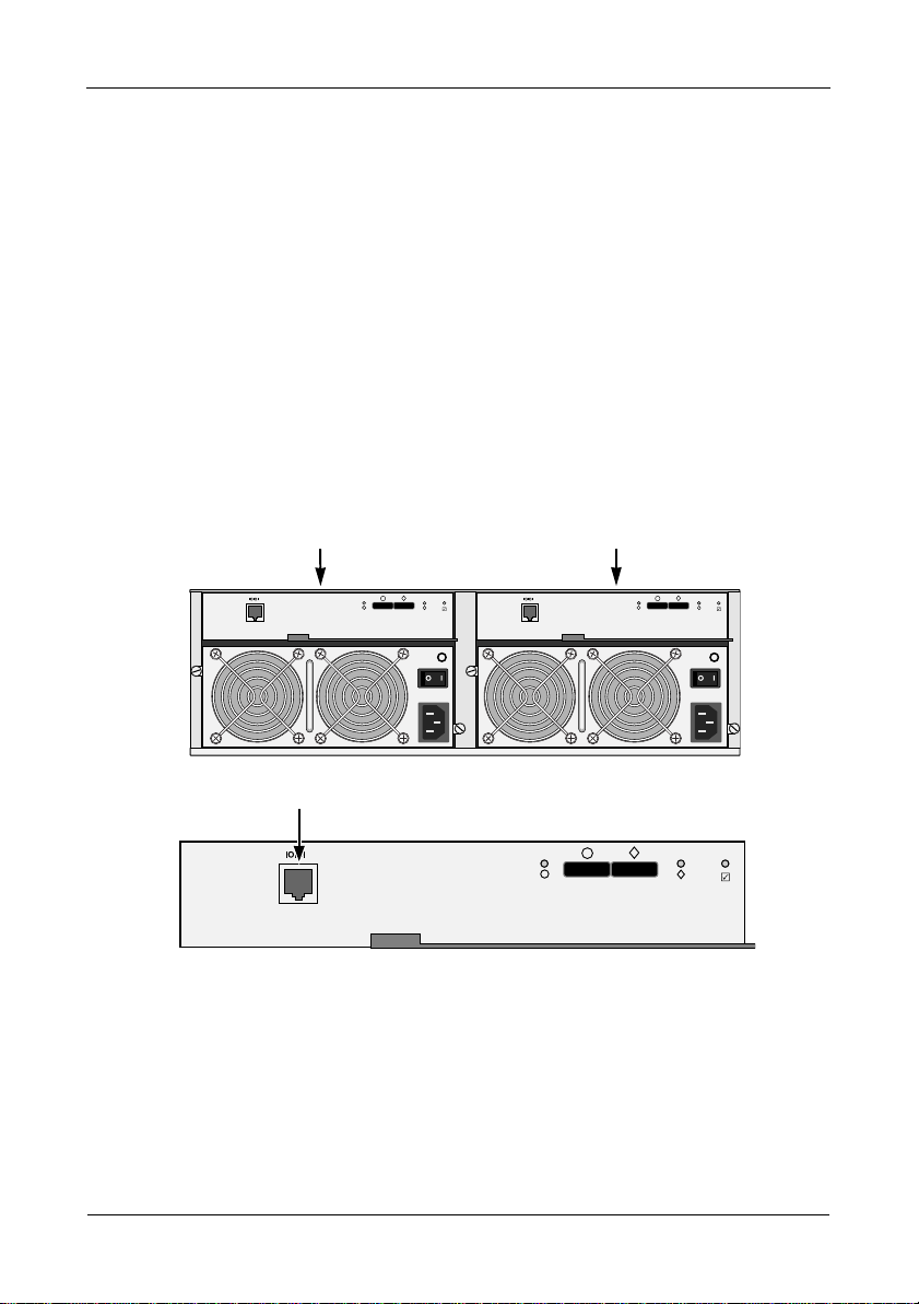
Figure 14.Use the serial connector on the left I/O module
attach serial cable to this module
I/O module 1
115200 8 N 1 115200 8 N 1
RJ11 Serial Connector
115200 8 N 1
I/O module 2
(optional)
17
Page 18
Task 6: Connecting the Power
Task 6: Connecting the Power
Plug the power cords into the power supplies on the back of the enclosure and
switch on the power supplies. When the power is switched on, the LEDs light up.
When boot-up is finished and the VTrak subsystem is functioning normally:
• Power and Global enclosure status LEDs display green continuously.
• I/O module activity LEDs flash green when there is activity on the SAS ports.
• System heartbeat LED blinks green once every 4 seconds if one I/O module
is installed or once every 2 seconds if two I/O modules are installed.
Figure 15.VTrak J630s front panel LED display. The J830s is similar
Power
Global enclosure status
Reserved
I/O module-1 activity
I/O module-2 activity
Heartbeat
Generally speaking, if there is a disk drive in the carrier, the Power/Activity LED
displays green. If not, the LED remains dark. The Power/Activity LED flashes
during drive activity.
The Disk Status LED displays green when the drive has been configured.
Figure 16.Drive carrier LEDs
Disk Status
Power/Activity
18
Page 19

VTrak J830s, J630s Quick Start Guide
Task 7: Setting Up the CLI Connection
The VTrak subsystem has a Command Line Interface (CLI) to manage all of its
functions, including customization. Access the CLI via your PC’s terminal VT100
or ANSI emulation program, such as Microsoft HyperTerminal.
The VTrak must be running and the RJ11-to-DB9 serial data cable connected to
the primary I/O module and the Host PC or Server’s serial port. See page 17.
To set up the CLI connection:
1. Change your terminal emulation program settings to agree with the
following:
• Bits per second: 115200
• Data bits: 8
• Parity: None
• Stop bits: 1
• Flow control: none
2. Start your PC’s terminal emulation program.
3. Press Enter once to launch the CLI.
The cli> prompt on your screen indicates that you have a connection and the
CLI is ready to accept commands.
CLI Command Set
The CLI uses the following set of commands:
enclosure – Displays enclosure settings and component information.
factorydefaults – Restores the factory default settings to the enclosure.
help – Use alone to see the list of commands. Use with a command to see a list
of options. Examples: enclosure help and help enclosure.
link – Displays the current status of the Phys (links) and the error counter.
route – Displays table routing information (downstream connections).
uptime – Displays the number of days, hours, minutes and seconds since the
firmware was loaded (since the VTrak was started or restarted).
? – Use alone to see the list of commands. Use with a command to see a list of
options. Example: enclosure -?.
Commands and options are not case-sensitive.
In the CLI screens:
• The SAS IN port (circle icon) is called CN#1
• The SAS OUT port (diamond icon) is called CN#2
19
Page 20

Frequently Asked Questions
Frequently Asked Questions
What kind of disk drives can I use with VTrak?
VTrak supports 2.5-inch and 3.5-inch SAS and SATA disk drives. See the
Compatibility List on the Promise Website for a list of qualified disk drives.
If your VTrak subsystem has two I/O modules, you must install an AAMUX
adapter on each of your SA T A drives. Obt ain AAMUX adapters from Promise
Technology, Inc.
How do I install a 2.5-inch drive into a 3.5-inch drive carrier?
To install your 2.5-inch disk drives into VTrak’s drive carriers, you must first
attach a mounting bracket to each of your drives. See page 11. Never install
the drives by inserting screws through the bottom of the drive carrier.
Obtain mounting brackets and screws from Promise Technology, Inc.
How can I tell when the VTrak has fully booted?
When the VTrak unit is fully booted up, the Power and FRU LEDs will light up
green. The heartbeat LED blinks green once every 4 seconds if one I/O
module is installed or once every 2 seconds if two I/O modules are installed.
How can I tell my CLI connection is to the primary default I/O module?
After you establish the CLI connection, type Enclosure and press Enter . Look
at the top of the display for an item called I/O Module Role.
• If the Role is Primary, you are connected to the default primary I/O
module.
• If the Role is Secondary, you are connected to the default secondary
I/O module.
What happens if a disk drive fails?
Depending on the nature of the failure, the failed drive the drive might not
appear in the CLI, or the failed drive might appear with an error, when you
run the enclosure command or the link command. See the VTrak J830s,
J630s Product Manual on the CD for more information.
Can I hot-swap a failed drive with a new one?
Yes. Disk drives are hot-swappable on the J830s and J630s units.
Can the VTrak run using just one power supply?
Yes, it is possible to run the VTrak unit on a single power supply. However,
leaving one power supply off means there is no redundancy if the remaining
power supply fails. And it reduces air flow through the enclosure, which can
contribute to overheating. Always switch on both power supplies.
20
Page 21
VTrak J830s, J630s Quick Start Guide
Contacting Technical Support
Promise Technical Support provides several support options for Promise users to
access information and updates. We encourage you to use one of our electronic
services, which provide product information updates for the most efficient service
and support.
If you decide to contact us, please have the following information available:
• Product model and serial number
• BIOS, firmware and driver version numbers
• A description of the problem or situation
• System configuration information, including: motherboard and CPU type,
disk drive models, SAS/SATA/ATA/ATAPI drives & devices, and other
controllers.
Technical Support Services
Promise Online™ Website http://www.promise.com/support/
support_eng.asp
(technical documents, drivers, utilities, etc.)
E-mail Support e-Support On-Line
Phone Support:
United States +1 408 228 1400 option 4
The Netherlands +31 0 40 235 2600
Germany +49 0 2 31 56 76 48 10
Italy +39 0 6 367 126 26
Taiwan +886 3 578 2395 ext. 8845
Beijing, China +86 10 8857 8085 or 8095
Shanghai, China +86 21 6249 4192, 4193, or 4199
21
Page 22
VTrak – Arbeitsschritte
• Schritt 1: Auspacken des VTrak (siehe unten)
• Schritt 2: Einbauen des VTrak-Geräts in ein Rack (Seite 25)
• Schritt 3: Installation der Festplatten (Seite 28)
• Schritt 4: Herstellen der Datenverbindungen (Seite 35)
• Schritt 5: Einrichten von seriellen Kabelverbindungen (Seite 40)
• Schritt 6: Anschließen der Stromversorgung (Seite 41)
• Schritt 7: Einrichten der CLI-Verbindung (Seite 42)
• Häufig gestellte Fragen (Seite 43)
• Kontaktaufnahme mit dem technischen Support (Seite 45)
Vielen Dank, dass Sie sich für das externe Festplattensubsystem Promise VTrak
J830s oder J630s entschieden haben.
Lesen Sie bitte vor dem Start die folgenden Anweisungen aufmerksam durch.
Gegebenenfalls benötigen Sie weitere Komponenten, um die Installation
abzuschließen.
Schritt 1: Auspacken des VTrak
Das VTrak J830s- bzw. J630s-Paket enthält die folgenden Komponenten:
• VTrak-Einheit
• Kurzanleitung
• Serielle RJ11-auf-DB9Datenkabel (2)
• Externe 1,0 m lange SFF8088-4X-auf-4X-SASKabel (2)
• Schrauben für Festplatten
(J830s: 106, einschließlich
10 Ersatzschrauben)
(J630s: 70, einschließlich
6 Ersatzschrauben)
• Linke und rechte
Montageschiene
• Stromkabel 1,5 m (2)
• CD mit Produkthandbuch und
Kurzanleitung
Warnung
Die elektronischen Komponenten im VTrak können durch elektro
statische Entladungen beschädigt werden (ESD). Halten Sie sich
beim Umgang mit dem VTrak oder seinen Komponenten stets an
die geltenden Vorsichtsmaßnahmen.
22
Page 23
VTrak J830s, J630s – Kurzanleitung
s
Vorsicht
VTrak unterstützt den Austausch von Festplatten im laufenden
Betrieb. Um den Handkontakt mit elektrischen Gefahrenquellen zu
vermeiden, entfernen Sie nicht mehr als einen Festplattenträger
auf einmal.
Hinweise
Warnhinweise für den Benutzer: Dies ist ein Klasse-A ITEProdukt, das Funkfrequenzinterferenzen verursachen kann, wenn
es in Wohngebieten verwendet wird. Beim Auftreten solcher
Interferenzen ist der Benutzer verpflichtet, entsprechende
Gegenmaßnahmen zu ergreifen.
Abbildung 1.VTrak J630s-Vorderansicht. J830s ist ähnlich.
Festplattenträger-LEDs
Festplattenträger
Betriebs- und Statusanzeige-LED
23
Page 24
Schritt 1: Auspacken des VTrak
Abbildung 2. VTrak J630s-Rückansicht. J830s ist ähnlich.
E/A-Modul 2E/A-Modul 1
115200 8 N 1 115200 8 N 1
Stromversorgungseinheit 1
Stromversorgungseinheit 2
24
Page 25
VTrak J830s, J630s – Kurzanleitung
Schritt 2: Einbauen des VTrak-Geräts in ein Rack
Vorsicht
• Es werden mindestens zwei Personen benötigt, um das
VTrak-Gerät sicher in das Racksystem zu heben und zu
platzieren und an das Racksystem zu befestigen.
• Halten Sie das VTrak-Gerät zum Heben oder Bewegen nicht
an den Griffen der Frontplatte, den Netzteilen oder den
Controllerkomponenten fest. Halten Sie das Subsystem
selbst fest.
• Installieren Sie das VTrak-Gerät nicht ohne Schienen, die
System unterstützen.
• Das VTrak-Gerät darf nur von einem mit dem
Installationsvorgang vertrauten, qualifizierten Techniker
montiert und installiert werden.
• Stellen Sie sicher, dass alle Schalter auf OFF (AUS)
geschaltet sind, bevor Sie das VTrak-Gerät installieren oder
Komponenten austauschen.
• Befestigen Sie die Schienen am Rack, indem Sie sie mithilfe
der entsprechenden Schrauben und
Ende der Schienen fest anziehen.
• Belasten Sie die Schienen erst nach ordnungsgemäßer
Montage der Schrauben.
• Die im Lieferumfang des Promise VTrak-Geräts enthaltenen
Schienen wurden für die sichere Unterstützung des Promise
VTrak-Geräts nach einer ordnungsgemäßen Installation
entwickelt. Bei einer übermäßigen Belastung der Schienen
geht das Risiko auf den Kunden über.
• Promise Technology, Inc. übernimmt nur dann die Garantie
dafür, dass die Montageschienen Ihr Promise VTrak-Gerät
tragen, wenn die Schienen ordnungsgemäß montiert wurden.
Flanschmuttern an jedem
Hinweis
Um das Gewicht des VTrak-Gehäuses zu reduzieren, entfernen
Sie die Stromversorgungseinheiten. Setzen Sie die
Stromversorgungseinheiten wieder ein, sobald sich das
VTrak-Gerät wieder im Rack befindet.
Die J830s- und J630s-Subsysteme werden mithilfe der mitgelieferten
25
Page 26
Schritt 2: Einbauen des VTrak-Geräts in ein Rack
Montageschienen in das Rack eingebaut. Es können auch eigene vorhandene
Schienen verwendet werden.
Abbildung 3. VTrak J630s mit den mitgelieferten Schienen in einem
Rack montiert
Vertikaler Rackpfosten VTrak J630s
Schraube und Flanschmutter installieren
Nur obere Bohrung
Griffe zur Befestigung an der
Außenseite der Rackpfosten
So installieren Sie das VTrak-Subsystem mittels der mitgelieferten
Montageschienen (im
Lieferumfang) Installationsposition
außerhalb des Rackpfostens
Montageschienen in einem Rack:
1. Prüfen Sie, ob die Montageschienen einwandfrei in Ihr Racksystem passen.
Siehe Seite 27, Abbildung 4.
2. Passen Sie die Länge der Montageschienen erforderlichenfalls an.
Die hintere Schiene gleitet in der vorderen Schiene. Die Schienenhälften
sind miteinander vernietet und benötigen keine Einstellschrauben.
3. Befestigen Sie die Montageschiene an der Außenseite der Rackpfosten;
verwenden Sie dazu die Befestigungsschrauben und die
Flanschmuttern
Ihres Racksystems.
Achten Sie darauf, dass die Auflage der vorderen Schiene unten ist und
nach innen zeigt.
Die Ausrichtungsstifte passen in die Racklöcher ober- und unterhalb der
Befestigungsschrauben.
Verwenden Sie die Befestigungsschrauben und
Racksystems. Ziehen Sie die Schrauben und
Flanschmuttern Ihres
Flanschmuttern gemäß den
Anweisungen für Ihr Racksystem fest.
4. Platzieren Sie das VTrak-Subsystem auf die Schienen.
5. Verbinden Sie das VTrak-Subsystem sicher mit dem Rack.
26
Page 27
VTrak J830s, J630s – Kurzanleitung
Eine Schraube auf jeder Seite. Verwenden Sie die Befestigungsschrauben
Flanschmuttern des Racksystems. Ziehen Sie die Schrauben und
und
Flanschmuttern gemäß den Racksystem-Anleitungen fest.
Abbildung 4. Arbeitsplan für Rackmontage
Vorderer Rackpfosten
Pfosteninnenseite
Ausrichtungsstifte
Hinterer Rackpfost
zwei an jedem Flansch
Vordere
Schiene
Hintere
Schiene
Auflage für
Subsystem
Schrauben zur Befestigung
Pfosteninnenseit
der Schienen
(nicht mitgeliefert)
Beachten Sie, dass nur die vordere Schiene
eine Auflage für das Subsystem besitzt.
en
e
27
Page 28
Schritt 3: Installation der Festplatten
Schritt 3: Installation der Festplatten
Sie können das VTrak-Gehäuse mit SAS- oder SATA-Festplatten bestücken. In
der Kompatibilitätsliste auf der Promise-Website finden Sie eine Liste mit
geeigneten Festplatten.
Für eine optimale Leistung installieren Sie Festplatten desselben Modells und
derselben Kapazität.
Nummerierung der Laufwerksteckplätze
Sie können jede geeignete Festplatte in einen beliebigen Steckplatz des
Gehäuses einbauen. Die Diagramme unten zeigen die Nummerierung der VTrakLaufwerksteckplätze.
Abbildung 5. VTrak J830s – Nummerierung der Laufwerksteckplätze
1
5
9
13
17
21
Abbildung 6. VTrak J630s – Nummerierung der Laufwerksteckplätze
1
5
9
13
Installieren Sie alle Festplatten-Träger in das VTrak-Gehäuse, selbst wenn Sie
nicht alle Träger mit Festplatten bestücken.
2
7
10
14
18
22
10
14
3
7
11
15
19
23
2
7
3
7
11
15
4
8
12
16
20
24
4
8
12
16
28
Page 29

VTrak J830s, J630s – Kurzanleitung
3,5-Zoll-Festplatten installieren
Wichtig
• Wenn Ihr VTrak über zwei E/A-Module verfügt und Sie SATAFestplatten installieren, benötigen Sie einen AAMUX-Adapter,
damit beide Module auf die SA TA-Festplatte zugreifen
können. Die AAMUX-Adapter sind bei Promise
Technology, Inc erhältlich.
• Durch eine ordnungsgemäße Installation ist eine adäquate
Erdung gewährleistet. Außerdem wird die Vibration auf ein
Minimum reduziert. Befestigen Sie die Festplatten stets mit
allen vier Schrauben.
So installieren Sie 3,5-Zoll-Festplatten:
1. Entfernen Sie einen Festplattenträger.
2. Legen Sie das Laufwerk vorsichtig in den Festplattenträger auf der
Vorderseite, sodass die seitlich angebrachten Schraubenlöcher bündig
übereinander liegen.
Wenn Sie AAMUX-Adapter und SATA-Festplatten installieren:
Verbinden Sie zunächst den Adapter mit der Festplatte. Installieren Sie
anschließend die Befestigungsschrauben. Siehe Seite 30, Abbildung 7.
3. Führen Sie die Schrauben durch die Löcher an der Seite des
Festplattenträgers und in die Festplatte ein. Siehe Seite 30,
Abbildungen 7 und 8.
• Installieren Sie bei der Festplatte nur die Schrauben, die im
Lieferumfang des VTrak enthalten waren.
• Installieren Sie beim Adapter nur die Schrauben, die im Lieferumfang
des Adapters enthalten waren.
• Verwenden Sie vier Schrauben pro Festplatte.
• Installieren Sie zwei Schrauben pro Adapter.
• Drehen Sie jede Schraube fest. Gehen Sie dabei behutsam vor, um ein
Überdrehen der Schrauben zu vermeiden.
4. Installieren Sie die Festplattenträger wieder in das VTrak-Gehäuse.
5. Wiederholen Sie die Schritte 2 bis 4, bis alle Festplatten eingebaut sind.
29
Page 30
Schritt 3: Installation der Festplatten
Vorsicht
VTrak unterstützt den Austausch von Festplatten im laufenden
Betrieb. Um den Handkontakt mit elektrischen Gefahrenquellen zu
vermeiden, entfernen Sie nicht mehr als einen Festplattenträger
auf einmal.
Abbildung 7. Festplattenträger mit 3,5-Zoll-SATA-Festplatte und Adapter
SATA-Festplatte
AAMUX-Adapter
Festplatte
Befestigungsschraube
Adapter
Befestigungs-
Festplatte
schraube
Befestigungsschraube
Adapter
Befestigungsschraube
30
Page 31

VTrak J830s, J630s – Kurzanleitung
Abbildung 8. Festplattenträger mit 3,5-Zoll-SAS-Festplatte
SAS-Festplatte
Festplatte
Befestigungsschraube
Festplatte
Befestigungsschraube
31
Page 32

Installieren der 2,5-Zoll-Festplatten
Vorsicht
• Verwenden Sie stets Montagehalterungen, wenn Sie 2,5-ZollFestplatten installieren. Installieren Sie die Festplatten
niemals durch Einsetzen von Schrauben über den Boden des
Festplattenträgers. Sie erhalten die erforderlichen
Montagehalterungen und Schrauben bei Promise
Technology, Inc.
• Fassen Sie 2,5-Zoll-Festplatten stets an den Ecken an, um
eine Beschädigung des Laufwerks zu vermeiden.
• VTrak unterstützt den Austausch von Festplatten im
laufenden Betrieb. Um den Handkontakt mit elektrischen
Gefahrenquellen zu vermeiden, entfernen Sie nicht mehr als
einen Festplattenträger auf einmal.
Wichtig
• Wenn Ihr VTrak über zwei E/A-Module verfügt und Sie SATAFestplatten installieren, benötigen Sie einen AAMUX-Adapter,
damit beide Module auf die SA TA-Festplatte zugreifen
können. Die AAMUX-Adapter sind bei Promise
Technology, Inc erhältlich.
• Durch eine ordnungsgemäße Installation ist eine adäquate
Erdung gewährleistet. Außerdem wird die Vibration auf ein
Minimum reduziert. Befestigen Sie die Festplatten stets mit
allen vier Schrauben.
Schritt 3: Installation der Festplatten
So installieren Sie die 2,5-Zoll-Festplatten:
1. Befestigen Sie eine Halterung an der Festplatte. Siehe Seite 33,
Abbildung 9.
• Verwenden Sie nur solche Schrauben, die im Lieferumfang der
Halterung enthalten waren.
• Verwenden Sie zum Befestigen zwei Schrauben pro Halterung.
• Drehen Sie jede Schraube fest. Gehen Sie dabei behutsam vor, um ein
Überdrehen der Schrauben zu vermeiden.
2. Entfernen Sie einen Festplattenträger.
32
Page 33

VTrak J830s, J630s – Kurzanleitung
en
g
3. Legen Sie das Laufwerk vorsichtig in den Festplattenträger auf der
Vorderseite, sodass die seitlich angebrachten Schraubenlöcher aufeinander
ausgerichtet sind.
Wenn Sie AAMUX-Adapter und SATA-Festplatten installieren:
Verbinden Sie zunächst den Adapter mit der Festplatte. Installieren Sie
anschließend die Befestigungsschrauben.
4. Führen Sie die Schrauben durch die seitlichen Löcher im Festplattenträger
und in die Festplatte ein. Siehe Seite 34, Abbildung 10.
• Installieren Sie bei der Festplatte nur die Schrauben, die im
Lieferumfang des VTrak enthalten waren.
• Installieren Sie bei der Halterung nur die Schrauben, die im
Lieferumfang der Halterungen enthalten waren.
• Installieren Sie beim Adapter nur die Schrauben, die im Lieferumfang
des Adapters enthalten waren.
• Installieren Sie zwei Schrauben pro Festplatte, zwei Schrauben pro
Halterung und zwei Schrauben pro Adapter.
• Drehen Sie jede Schraube fest. Gehen Sie dabei behutsam vor, um ein
Überdrehen der Schrauben zu vermeiden.
5. Bauen Sie die Festplattenträger wieder in das VTrak-Gehäuse ein.
6. Wiederholen Sie die Schritte 2 bis 5, bis alle Festplatten eingebaut sind.
Abbildung 9. 2,5-Zoll-Festplatte und Montagehalterung
Festplatte
33
Festplatte
Befestigungsschraub
Montagehalterun
Page 34

Schritt 3: Installation der Festplatten
F
B
s
.
F
Abbildung 10. Bohrlöcher für Festplattenträger-Befestigungsschrauben
estplatte
efestigungs-
chraube
estplatte
HalterungsBefestigungsschraube
Montagehalterung
Halterungs-
Festplatte
Befestigungs-
Befestigungsschraube
schraube
Hinweis: Die Halterungsschrauben sind größer als die Festplattenschrauben
34
Page 35

VTrak J830s, J630s – Kurzanleitung
S I
Schritt 4: Herstellen der Datenverbindungen
Sie können Ihr VTrak-Subsystem konfigurieren als:
• Basic Direct Attached Storage (DAS)-Verbindung (unten)
• Anordnen der DAS-Verbindung (Seite 36)
• Redundante kaskadierende DAS-Verbindung (Seite 37)
Basis-DAS-Verbindung
So richten Sie eine Basis-DAS-Verbindung ein:
• Im Host PC oder im Server muss eine SAS HBA-Karte enthalten sein.
• Verbinden Sie die SAS HBA-Karte im Host PC mit der SAS IN-Schnittstelle
(mit dem kreisförmigen Symbol) auf dem VTrak. Siehe Abbildung 11.
• Verwenden Sie das externe SFF-8088-4X-auf-4X-SAS-Kabel, das im
Lieferumfang des VTrak enthalten war.
Abbildung 11. Eine Basis-DAS-Verbindung
Kreisförmige SA
Schnittstelle
115200 8 N 1 115200 8 N 1
VTrak J630s
Externes SFF-8088
4X-auf-4X-SAS-Kabel
SAS HBAErweiterungskarte
Host-PC oder Server
Das Diagramm oben zeigt den VTrak J630s. Die V erbindung mit dem J830s kann
auf gleiche Weise hergestellt werden.
Hiermit sind die Daten- und Verwaltungsverbindungen abgeschlossen. Gehen
Sie zu „Schritt 5: Einrichten von seriellen Kabelverbindungen“ auf Seite 40.
35
Page 36

Schritt 4: Herstellen der Datenverbindungen
Anordnen der DAS-Ve rbindung
Aufbau einer kaskadenartigen DAS-Verbindung:
1. Schließen Sie die SAS HBA-Karte im Host PC an die SAS IN-Schnittstelle
(mit dem kreisförmigen Symbol) des ersten VTrak an.
Siehe Abbildung 12. Verwenden Sie ein externes SFF-8088-4X-auf-4X-SASKabel (im Lieferumfang des VTrak enthalten).
2. Verbinden Sie die SAS OUT-Schnittstelle (mit dem rautenförmigen Symbol)
auf dem gleichen E/A-Modul des ersten VTrak mit der SAS IN-Schnittstelle
(mit dem kreisförmigen Symbol) des zweiten VTrak.
Stellen Sie sicher, dass Sie das kreisförmige Symbol mit dem
rautenförmigen Symbol verbunden haben oder umgekehrt.
Sie können auf diese Weise bis zu vier VTrak-Geräte kaskadierend
anordnen.
Sie können außerdem J830s- und J630s-Geräte sowie J610s- und
J310s-Geräte auf gleiche Weise mischen und kaskadierend anordnen.
Beachten Sie, dass es sich bei Jx10s um 3-GB-Geräte mit reduziertem
Datendurchsatz handelt.
36
Page 37

VTrak J830s, J630s – Kurzanleitung
S
Abbildung 12. Eine kaskadierte DAS-Verbindung
SAS HBAErweiterungskarte
Externes SFF-8088
4X-auf-4X-SAS-Kabel
Kreisförmige SAS INSchnittstelle
115200 8 N 1 115200 8 N 1
Host-PC oder
Server
Rautenförmige SAS
OUT-Schnittstelle
VTrak J630s
Kreisförmige SAS
IN-Schnittstelle
115200 8 N 1 115200 8 N 1
Rautenförmige SA
OUT-Schnittstelle
VTrak J630s
Kreisförmige SAS INSchnittstelle
115200 8 N 1 115200 8 N 1
VTrak J630s
Das Diagramm auf Seite 37 zeigt den VTrak J630s. Verbindungen mit dem J830s
sind identisch.
Hiermit sind die Daten- und Verwaltungsverbindungen abgeschlossen. Gehen
Sie zu „Schritt 5: Einrichten von seriellen Kabelverbindungen“ auf Seite 40.
Redundante kaskadierende DAS-Verbindung
So richten Sie eine redundante kaskadierende DAS-Verbindung ein:
1. Schließen Sie die SAS HBA-Karte im ersten Host PC an die SAS INSchnittstelle (mit dem kreisförmigen Symbol) auf dem ersten VTrak an.
Siehe Seite 39, Abbildung 13. Verwenden Sie ein externes SFF-8088-4X-auf
-4X-SAS-Kabel (im Lieferumfang des VTrak enthalten).
2. Verbinden Sie die SAS OUT-Schnittstelle (mit dem rautenförmigen Symbol)
auf dem gleichen E/A-Modul des ersten VTrak mit der SAS IN-Schnittstelle
(mit dem kreisförmigen Symbol) des zweiten VTrak.
37
Page 38

Schritt 4: Herstellen der Datenverbindungen
3. Schließen Sie die SAS HBA-Karte im zweiten Host PC an die SAS INSchnittstelle (mit dem kreisförmigen Symbol) an das andere E/A-Modul auf
dem ersten VTrak an.
4. Verbinden Sie die SAS OUT-Schnittstelle (mit dem rautenförmigen Symbol)
auf dem gleichen E/A-Modul des ersten VTrak mit der SAS IN-Schnittstelle
(mit dem kreisförmigen Symbol) des anderen E/A-Moduls auf dem zweiten
VTrak.
5. Verbinden Sie die verbleibenden VTraks auf die gleiche Weise.
Stellen Sie sicher, dass Sie das kreisförmige Symbol mit dem
rautenförmigen Symbol oder umgekehrt verbinden.
Schließen Sie die E/A-Module nicht über kreuz an. Achten Sie auf eine
getrennte kaskadierende Konfiguration von jedem Host PC oder Server mit
dem letzten VTrak. Siehe Seite 39, Abbildung 13.
Sie können auf diese Weise bis zu vier VTrak-Geräte kaskadierend
anordnen.
Sie können außerdem J830s- und J630s-Geräte sowie J610s- und J310sGeräte auf gleiche Weise mischen und kaskadierend anordnen. Beachten
Sie, dass es sich bei Jx10s um 3-GB-Geräte mit reduziertem
Datendurchsatz handelt.
38
Page 39

VTrak J830s, J630s – Kurzanleitung
e
e
Abbildung 13. Eine redundante kaskadierende DAS-Verbindung
SAS HBAErweiterungskarten
Externes SFF-8088
4X-auf-4X-SAS-Kabel
Kreisförmige SAS
IN-Schnittstelle
115200 8 N 1 115200 8 N 1
Kreisförmige SAS
IN-Schnittstelle
115200 8 N 1 115200 8 N 1
Rautenförmig
SAS OUTSchnittstelle
Rautenförmig
SAS OUTSchnittstelle
VTrak J630s
Kreisförmige
SAS INSchnittstelle
115200 8 N 1 115200 8 N 1
VTrak J630s
Kaskadenartige Konfiguration 1 Kaskadenartige Konfiguration 2
Das Diagramm oben zeigt den VTrak J630s. Die V erbindung mit dem J830s kann
auf gleiche Weise hergestellt werden.
Hiermit sind die Daten- und Verwaltungsverbindungen abgeschlossen. Gehen
Sie zu „Schritt 5: Einrichten von seriellen Kabelverbindungen“ auf Seite 40.
39
Page 40

Schritt 5: Einrichten von seriellen Kabelverbindungen
Schritt 5: Einrichten von seriellen
Kabelverbindungen
Mithilfe einer seriellen Verbindung kann die Befehlszeilenschnittstelle (CLI) Ihres
PCs das VTrak-Subsystem überwachen und steuern. Die CLI wird erläutert unter
„Schritt 7: Einrichten der CLI-Verbindung“ auf Seite 42.
Das VTrak-Paket enthält ein serielles RJ11-auf-DB9-Datenkabel.
So richten Sie eine serielle Kabelverbindung ein:
1. Schließen Sie das RJ11-Ende des seriellen Datenkabels an den seriellen
RJ11-Anschluss auf dem E/A-Modul 1 auf der Rückseite des VTrakSubsystems an.
Siehe Abbildung 14.
2. Verbinden Sie das DB9-Ende des seriellen Datenkabels mit einer seriellen
Schnittstelle des Host-PCs oder Servers.
Abbildung 14. Verwenden Sie den seriellen Anschluss auf dem linken
E/A-Modul.
serielles Kabel an dieses Modul
E/A-Modul 1
anschließen
E/A-Modul 2
(optional)
115200 8 N 1 115200 8 N 1
Serieller RJ11-Anschluss
115200 8 N 1
40
Page 41

VTrak J830s, J630s – Kurzanleitung
Schritt 6: Anschließen der Stromversorgung
Schließen Sie die Stromversorgungskabel an die Netzteile auf der Rückseite des
Gehäuses an, und schalten Sie die Netzteile ein. Wenn der Strom eingeschaltet
ist, leuchten die LEDs.
Nachdem der Boot-Vorgang abgeschlossen ist und das VTrak-Subsystem
störungsfrei funktioniert:
• Die Status-LEDs für die Stromversorgung und das globale Gehäuse
leuchten dauerhaft grün.
• LEDs für die E/A-Modul-Aktivität leuchten grün, wenn Aktivität auf den SASAnschlüssen vorhanden ist.
• Die System-Heartbeat-LED blinkt alle 4 Sekunden grün auf, wenn ein E/AModul installiert ist. Wenn zwei E/A-Module installiert sind, blinkt die LED
alle 2 Sekunden einmal auf.
Abbildung 15. VTrak J630s-LED auf der Vorderseite. Das J830s ist ähnlich.
Stromversorgung
Globaler Gehäusestatus
Reserviert
E/A-Modul-1-Aktivität
E/A-Modul-2-Aktivität
Heartbeat
Grundsätzlich gilt die folgende Aussage: Wenn sich eine Festplatte im Träger
befindet, leuchtet die Betriebs-/Aktivitätsanzeige-LED grün. Ist keine Festplatte
enthalten, leuchtet die LED nicht. Die Betriebs-/Aktivitätsanzeige-LED blinkt bei
Festplattenaktivität.
Die Festplattenstatus-LED leuchtet grün, wenn die Festplatte konfiguriert wurde.
41
Page 42

Schritt 7: Einrichten der CLI-Verbindung
g/
Abbildung 16. Festplattenträger-LEDs
Festplattenstatus
Stromversorgun
Aktivität
Schritt 7: Einrichten der CLI-Verbindung
Das VTrak-Subsystem verfügt über eine Befehlszeilenschnittstelle (CLI) für die
Verwaltung des gesamten Funktionsumfangs, einschließlich der
Benutzeranpassung. Sie können auf die Befehlszeilenschnittstelle über die
VT100- oder ANSI-Terminalemulation Ihres PCs zugreifen, z. B. Microsoft
HyperTerminal.
Das VTrak muss ausgeführt werden, und das serielle RJ11-auf-DB9-Datenkabel
muss mit dem primären E/A-Modul und dem seriellen Anschluss auf dem Host
PC oder dem Server verbunden sein. Siehe Seite 40.
So richten Sie die CLI-Verbindung ein:
1. Stellen Sie folgende Werte an Ihrer Terminalemulation ein:
• Bits pro Sekunde: 115200
• Datenbits: 8
• Parität: Keine
• Stoppbits: 1
• Flusskontrolle: Keine
2. Starten Sie Ihre Terminalemulation am PC.
3. Drücken Sie einmal die Eingabetaste, um die CLI zu starten.
Die CLI>-Eingabeaufforderung auf Ihrem Bildschirm zeigt an, dass eine
Verbindung besteht und Sie nun Befehle über die CLI eingeben können.
Befehlssatz der Befehlszeilenschnittstelle (CLI)
Die CLI akzeptiert die folgenden Befehle:
enclosure (Gehäuse) – Zeigt Informationen zu Gehäuseeistellungen und zu
Komponenten an.
factorydefaults (Werkseinstellungen) – Stellt die werkseitige
Standardeinstellungen für das Gehäuse wieder her.
42
Page 43

VTrak J830s, J630s – Kurzanleitung
help (Hilfe) – Zeigt eine Liste der Befehle an. Zeigt zusammen mit einem Befehl
benutzt eine Reihe von Optionen an. Beispiele: enclosure help (Gehäusehilfe)
und help enclosure.
link (Verknüpfung) – Zeigt den aktuellen Status der Phys (Verknüpfungen) und
anderer Fehlerzähler an.
route (Route) – Zeigt die Tabellenweiterleitungsinformationen (nachgelagerte
Verbindungen) an.
uptime (Betriebszeit) – Zeigt die Anzahl der Tage, Stunden, Minuten und
Sekunden an, seitdem die Firmware geladen (bzw. VTrak gestartet oder erneut
gestartet) wurde.
? – Zeigt eine Liste mit Befehlen an. Zeigt zusammen mit einem Befehl eine
Reihe von Optionen an. Beispiel: enclosure -? (Gehäuse -?).
Bei der Eingabe von Befehlen und Optionen ist die Groß- und Kleinschreibung
nicht relevant.
Auf den CLI-Bildschirmen:
• Der SAS IN-Anschluss (kreisförmiges Symbol) wird als CN#1 bezeichnet.
• Der SAS OUT-Anschluss (rautenförmiges Symbol) wird als CN#2
bezeichnet.
Häufig gestellte Fragen
Welche Art von Festplatten kann ich mit dem VTrak verwenden?
VTrak unterstützt 2,5-Zoll- und 3,5-Zoll-SAS- und SATA-Festplatten. In der
Kompatibilitätsliste auf der Promise-Website finden Sie eine Liste mit
geeigneten Festplatten.
Wenn Ihr VTrak-Subsystem über zwei E/A-Module verfügt, müssen Sie
einen AAMUX-Adapter auf jedem der SATA-Festplatten installieren. Die
AAMUX-Adapter sind bei Promise Technology, Inc erhältlich.
Wie installiere ich eine 2,5-Zoll-Festplatte in einen 3,5-ZollFestplattenträger?
Für die Installation einer 2,5-Zoll-Festplatte in VTrak-Festplattenträger
müssen Sie zunächst Montagehalterungen an Ihre Festplatten anbringen.
Siehe Seite 32. Installieren Sie die Festplatten niemals durch Einsetzen von
Schrauben über den Boden des Festplattenträgers.
Die erforderlichen Montagehalterungen und Schrauben sind bei Promise
Technology, Inc erhältlich.
43
Page 44

Häufig gestellte Fragen
Wie erkenne ich, ob der VTrak vollständig gebootet ist?
Wenn der Boot-Vorgang für das VTrak-Gerät vollständig abgeschlossen ist,
leuchten die Stromversorgungs- und FRU-LEDs grün. Die Heartbeat-LED
blinkt alle vier Sekunden auf, wenn ein E/A-Modul installiert ist oder alle zwei
Sekunden, wenn zwei E/A-Module installiert sind.
Wie kann ich feststellen, ob meine Befehlszeilenschnittstelle (CLI) mit dem
voreingestellten primären E/A-Modul verbunden ist?
Geben Sie nach dem Aufbau der Befehlszeilenschnittstellenverbindung
„Enclosure“ (Gehäuse) ein und drücken Sie dann auf die Eingabetaste. Am
oberen Rand des Bildschirms wird ein Element mit der Bezeichnung „I/O
Module Role“ (Rolle E/A-Modul) angezeigt.
• Wenn die Rolle Primary (primär) lautet, sind Sie mit dem
voreingestellten primären E/A-Modul verbunden.
• Wenn die Rolle Secondary (sekundär) lautet, sind Sie mit dem
voreingestellten sekundären E/A-Modul verbunden.
Was passiert beim Ausfall einer Festplatte?
Abhängig von der Art des aufgetretenen Fehlers wird die fehlerhafte
Festplatte möglicherweise nicht oder mit einem Fehler angezeigt, wenn Sie
die Befehle enclosure (Gehäuse) oder link (Verknüpfung) ausführen. W eitere
Informationen finden Sie im VTrak J830s- und J630s-Produkthandbuch auf
der CD.
Kann die ausgefallene Festplatte bei laufendem Betrieb durch eine neue
Festplatte ausgetauscht werden?
Ja. Bei den J830s- und J630s-Geräten können Festplatten im laufenden
Betrieb ausgetauscht werden.
Funktioniert der VTrak auch mit nur einer Stromversorgungseinheit?
Ja, es ist möglich, den VTrak mit nur einer Stromversorgungseinheit zu
betreiben. Wenn Sie eine Stromversorgungseinheit ausgeschaltet lassen,
können Sie auf keine Redundanz mehr zurückgreifen, wenn die
verbleibende Stromversorgungseinheit ausfällt. Außerdem wird die
Luftzirkulation durch das Gehäuse eingeschränkt, was zu Überhitzung
führen kann. Schalten Sie immer beide Stromversorgungseinheiten ein.
44
Page 45

VTrak J830s, J630s – Kurzanleitung
Kontaktaufnahme mit dem technischen Support
Promise bietet seinen Benutzern über den technischen Support verschiedene
Möglichkeiten, auf Informationen und Updates zuzugreifen. Bitte nutzen Sie
unseren elektronischen Service. Hier erhalten Sie die neuesten Produktinfo
rmationen und einen optimalen Support.
Sollten Sie sich direkt an uns wenden wollen, so halten Sie bitte folgende
Informationen bereit:
• Das Modell des Produktes und die Seriennummer
• Versionsnummern von BIOS, Firmware und Treibern
• Eine Beschreibung des Problems oder der Situation
• Informationen zur Systemkonfiguration, einschließlich: Hauptplatinen- und
CPU-Typ, Festplattenmodelle, SAS/SATA/ATA/ATAPI-Laufwerke- und
Geräte sowie andere Controller.
Technischer Support
Promise Online™-Website http://www.promise.com/support/
support_eng.asp
(technische Dokumente, Treiber,
Dienstprogramme, usw.)
E-Mail-Support e-Support On-Line
Telefonischer Support:
USA +1-408-228-1400, Option 4
Holland +31-40-235-2600
Deutschland +49 0 2 31 56 76 48 10
Italien +39 0 6 367 126 26
Taiwan +886 3 578 2395 Durchwahl 8845
Peking, China +86-10- 885780-85 oder -95
Shanghai, China +86-21-62494-192, -193 oder -199
45
Page 46

Liste des tâches VTrak
• Tâche 1 : retrait de l'emballage du VTrak (voir ci-dessous)
• Tâche 2 : montage en baie du VTrak (page 48)
• Tâche 3 : installation de lecteurs de disque (page 51)
• Tâche 4 : établissement de connexions de données (page 56)
• Tâche 5 : configuration des connexions de câble série (page 60)
• Tâche 6 : connexion de l'alimentation (page 61)
• Tâche 7 : configuration de la connexion CLI (page 62)
• Foire aux questions (page 63)
• Contacter le Support technique (page 65)
Merci de votre achat d'un sous-système de disques externe VTrak J830s ou
J630s de Promise.
Veuillez lire toutes ces instructions avant de commencer. Vous aurez peut-être
besoin d'éléments supplémentaires afin de compléter l’installation.
Tâche 1 : retrait de l'emballage du VTrak
Le carton du VTrak J830s ou J630s contient les éléments suivants:
• Unité VTrak
• Guide de démarrage rapide
• Câbles de données série
RJ11-à-DB9 (2)
• Câbles SAS externes d'1m
(3,3 pieds) SFF-8088 4X à
4X (2)
• Vis pour lecteurs de disque
(J830s : 106, dont 10 de
rechange)
(J630s : 70, dont 6 de rechange)
• Rails de montage gauche et droite
• Cordons d'alimentation de 1,5 m
[4,9 pieds] (2)
• CD contenant le Manuel du
produit et le Guide de démarrage
rapide
Avertissement
Les composants électroniques à l'intérieur du VTrak sont
sensibles et risquent d'être endommagés par une décharge
électrostatique (ESD). Prenez les précautions appropriées lorsque
vous manipulez le VTrak ou ses sous-ensembles.
Attention
VTrak prend en charge le remplacement de lecteur de disque à
chaud. Pour éviter tout risque d'électrocution, ne retirez pas plus
d'un support de lecteur à la fois.
46
Page 47

Guide de démarrage rapide du VTrak J830s, J630s
Avis
Avertissement pour l'utilisateur : ceci est un produit ITE de classe
A qui pourrait causer des interférences de fréquences radio s'il est
utilisé dans un environnement résidentiel. Dans un tel cas,
l'utilisateur devra adopter certaines mesures appropriées.
Figure 1. Vue frontale du VTrak J630s. Le J830s est similaire
Voyant du support de lecteur
Supports de
lecteur de disque
Voyants d'aliment ation
et d'état
Figure 2. Vue arrière du VTrak J630s. Le J830s est similaire
Module d'E/S 2Module d'E/S 1
115200 8 N 1 115200 8 N 1
Bloc d'alimentation 1
Bloc d'alimentation 2
47
Page 48

Tâche 2 : montage en baie du VTrak
Tâche 2 : montage en baie du VTrak
Attention
• Il faut au moins deux personnes pour soulever, placer et fixer
sans problème l'unité VTrak dans un système de baie.
• Ne soulevez et ne déplacez pas l'unité VTrak par les
poignées, les blocs d'alimentation ou les unités contrôleur.
Tenez le sous-système lui-même.
• N'installez pas l'unité VTrak dans une baie sans rails pour le
soutenir.
• Seul un technicien qualifié, connaissant bien la procédure
d'installation, est autorisé à monter et installer l'unité VTrak.
• Vérifiez que tous les commutateurs sont positionnés sur OFF
avant d'installer l'unité VTrak ou de remplacer des
composants.
• Montez les rails sur la baie à l'aide des vis et écrous à
embase appropriés, bien serrés, de chaque côté du rail.
• Ne placez rien sur les rails à moins qu'ils soient installés avec
des vis, comme indiqué.
• Les rails fournis avec l'unité VTrak Promise sont conçus pour
supporter en toute sécurité l'unité VTrak Promise concernée
lorsqu'ils sont correctement installés. Tout poids
supplémentaire sur les rails est la responsabilité du client.
• Promise Technology, Inc. ne peut pas garantir que les rails de
montage pourront supporter votre unité VTrak Promise à
moins que vous les installiez comme indiqué.
Remarque
Pour alléger le boîtier VTrak, retirez les blocs d'alimentation.
Remplacez les blocs d'alimentation après que l'unité VTrak est
montée dans la baie.
Les sous-systèmes J830s et J630s s'installent dans la baie à l'aide des rails de
montage fournis. Vous pouvez également utiliser les rails existants.
48
Page 49

Guide de démarrage rapide du VTrak J830s, J630s
Figure 3. Le VTrak J630s monté dans une baie avec les rails fournis
Montant vertical de la baie
VTrak J630s
Installation d'une vis et d'un écrou à embase
Trou supérieur uniquement
Poignées montées à l'extérieur
du montant de la baie
Les rails de montage (fournis) se
montent à l'extérieur du montant
de la baie
Pour installer le sous-système VTrak dans une baie avec les rails de montage
fournis :
1. Vérifiez que les rails de montage rentrent bien dans la baie. Voir page 50,
Figure 4.
2. Réglez la longueur des rails de montage, si nécessaire.
Le rail arrière se glisse à l'intérieur du rail avant. Les moitiés de rail sont
rivées ensemble et ne nécessitent pas de vis de réglage.
3. Fixez les rails de montage sur la partie externe des montants de la baie, à
l'aide des vis de fixation et écrous à embase de votre système de baie.
Assurez-vous que le support du rail avant est sur le dessous et fait face à
l'intérieur.
Les broches d'alignement entrent dans les trous de la baie au-dessus et
en-dessous des vis de fixation.
Utilisez les vis de fixation et les écrous à embase de votre système de baie.
Serrez les vis et écrous à embase selon les instructions de votre système de
baie.
4. Placez le sous-système VTrak sur les rails.
5. Fixez le sous-système VTrak à la baie.
Une vis de chaque côté. Utilisez les vis de fixation et les écrous à embase de
votre système de baie. Serrez les vis et écrous à embase selon les
instructions accompagnant votre système de baie.
49
Page 50

Tâche 2 : montage en baie du VTrak
Partie avant
Montant arrière
Figure 4. Schéma d'assemblage pour le montage de la baie
de la baie
Intérieur du
montant
Broches d'alignement
de la baie
deux sur chaque embase
Rail avant
Rail arrière
Support pour le
sous-système
Vis de fixation du rail
(non incluse)
Intérieur du
montant
Notez que seul le rail avant comporte un support pour le sous-système.
50
Page 51

Guide de démarrage rapide du VTrak J830s, J630s
Tâche 3 : installation de lecteurs de disque
Vous pouvez remplir le boîtier VTrak de lecteurs de disque SAS ou SATA.
Reportez-vous à la Liste de compatibilité sur le site Web Promise pour consulter
la liste de lecteurs de disque appropriés.
Pour des performances optimales, installez des lecteurs de disque de mêmes
modèle et capacité.
Numéro de logement du lecteur
Vous pouvez installer tout type de lecteur de disque approprié dans n'importe
quel logement du boîtier. Les diagrammes ci-dessous illustrent la numérotation
des logements de lecteur du VTrak.
Figure 5. Numérotation des logements de lecteur du VTrak J830s
1
5
9
13
17
21
Figure 6. Numérotation des logements de lecteur du VTrak J630s
1
5
9
13
Installez tous les supports de lecteur dans le boîtier du VTrak pour garantir une
bonne ventilation, même si vous ne remplissez pas tous les supports de lecteurs
de disque.
2
7
10
14
18
22
10
14
3
7
11
15
19
23
2
7
3
7
11
15
4
8
12
16
20
24
4
8
12
16
51
Page 52

Tâche 3 : installation de lecteurs de disque
Installation de lecteurs de disque de 3,5 po.
Important
• Si votre VTrak comporte deux modules d'E/S et que vous
installez des lecteurs de disque SA TA, un adaptateur AAMUX
est nécessaire pour que les deux modules puissent accéder
au lecteur de disque SATA. Obtenir des adaptateurs AAMUX
de Promise Technology, Inc.
• Une installation correcte garantit une mise à la terre adéquate
et réduit les vibrations au minimum. Utilisez toujours les
quatre vis lors de l'installation des lecteurs de disque.
Pour installer vos lecteurs de disque de 3,5 po. :
1. Retirez un support de lecteur de disque.
2. Placez doucement le lecteur de disque dans le support à l'avant de sorte
que les orifices de vis situés sur les côtés s'alignent.
Si vous installez des adaptateurs AAMUX et des lecteurs de disque SATA :
Rattachez d'abord l'adaptateur au lecteur. Ensuite, installez les vis de
montage. Voir page 53, Figure 7.
3. Insérez les vis dans les trous situés dans le support de lecteur et dans les
côtés du lecteur de disque. Voir page 53, Figures 7 et 8.
• Pour le lecteur de disque, n'installez que les vis fournies avec le VTrak.
• Pour l'adaptateur, n'installez que les vis fournies avec l'adaptateur.
• Installez quatre vis par lecteur.
• Installez deux vis par adaptateur.
• Serrez chaque vis. Prenez soin de ne pas trop serrer.
4. Replacez le support de lecteur dans le boîtier du VTrak.
5. Répétez les étapes 2 à 4 pour compléter l'installation de tous vos lecteurs de
disque.
Attention
VTrak prend en charge le remplacement de lecteur de disque à
chaud. Pour éviter tout risque d'électrocution, ne retirez pas plus
d'un support de lecteur à la fois.
52
Page 53

Guide de démarrage rapide du VTrak J830s, J630s
Figure 7. Support de lecteur avec un lecteur de disque SATA de 3,5 po. et
un adaptateur
Lecteur de
disque SATA
Adaptateur
AAMUX
Vis de montage de
lecteur de disque
vis de
montage
Vis de montage de
d’adaptateur
lecteur de disque
vis de montage
d’adaptateur
Figure 8. Support de lecteur avec un lecteur de disque SATA de 3,5 po.
Lecteur de disque SAS
Vis de montage de
lecteur de disque
Vis de montage de lecteur
de disque vis de montage
53
Page 54

Tâche 3 : installation de lecteurs de disque
Installation de lecteurs de disque de 2,5 po.
Attention
• Utilisez toujours des languettes métalliques de montage pour
installer des lecteurs de disque de 2,5 po. N'installez jamais
les lecteurs de disque en insérant des vis par le dessous du
support de lecteur. Procurez-vous des languettes métalliques
de montage et des vis de Promise Technology, Inc.
• Tenez les lecteurs de disque de 2,5 po. par le bord pour
empêcher des dommages au lecteur.
• VTrak prend en charge le remplacement de lecteur de disque
à chaud. Pour éviter tout risque d'électrocution, ne retirez pas
plus d'un support de lecteur à la fois.
Important
• Si votre VTrak comporte deux modules d'E/S et si vous
installez des lecteurs de disque SA TA, un adaptateur AAMUX
est nécessaire pour que les deux modules puissent accéder
au lecteur de disque SATA. Obtenir des adaptateurs AAMUX
de Promise Technology, Inc.
• Une installation correcte garantit une mise à la terre adéquate
et réduit les vibrations au minimum. Utilisez toujours les
quatre vis lors de l'installation des lecteurs de disque.
Pour installer vos lecteurs de disque de 2,5 po. :
1. Rattachez une languette métallique au lecteur de disque. Voir page 55,
Figure 9.
• Installez uniquement les vis fournies avec la languette métallique.
• Installez deux vis par languette métallique.
• Serrez chaque vis. Prenez soin de ne pas trop serrer.
2. Retirez un support de lecteur de disque.
3. Placez doucement le lecteur dans le support à l'avant de sorte que les
trous de vis situés sur les côtés s'alignent.
Si vous installez des adaptateurs AAMUX et des lecteurs de disque SATA :
Rattachez d'abord l'adaptateur au lecteur. Ensuite, installez les vis de
montage.
54
Page 55

Guide de démarrage rapide du VTrak J830s, J630s
e
e
V
d
d
V
d
d
L
d
4. Insérez les vis dans les trous situés dans le support de lecteur et dans les
côtés du lecteur de disque. Voir page55, Figure 10.
• Pour le lecteur de disque, n'installez que les vis fournies avec le VTrak.
• Pour la languette métallique, n'installez que les vis fournies avec la
languette métallique.
• Pour l'adaptateur, n'installez que les vis fournies avec l'adaptateur.
• Installez deux vis par lecteur, deux vis par languette métallique, et deux
vis par adaptateur.
• Serrez chaque vis. Prenez soin de ne pas trop serrer.
5. Replacez le support de lecteur dans le boîtier du VTrak.
6. Répétez les étapes 2 à 5 jusqu'à ce que tous les lecteurs de disque soient
installés.
Figure 9. lecteur de disque de 2,5 po. et languette métallique de montage
Lecteur de
disque
Vis demontage
de lecteur de disqu
Languette
métallique d
montage
Figure 10. Emplacements des vis de montage du support de lecteur
is de montage
e lecteur de
isque
ecteur de
isque
is de montage
e lecteur de
Vis de montage
de languette
métallique
Languette
métallique de
montage
Vis de montage
de languette
métallique
isque
Remarque : les vis de la languette métallique sont plus grandes
que celles du lecteur de disque.
55
Page 56

Tâche 4 : établissement de connexions de données
Tâche 4 : établissement de connexions de données
Vous pouvez configurer votre sous-système VTrak comme :
• Connexion DAS (système de stockage direct) de base (ci-dessous)
• Connexion DAS en cascade (page 57)
• Connexion DAS en cascade redondante (page 58)
Connexion DAS de base
Pour établir une connexion DAS de base :
• Une carte HBA SAS doit être installée dans le PC hôte ou le serveur.
• Connectez la carte HBA SAS du PC hôte au port d'entrée SAS (avec l'icône
en forme de cercle) sur le VTrak. Reportez-vous à la Figure 11.
• Utilisez le câble SAS externe SFF-8088 4X à 4X fourni avec le VTrak.
Figure 11. Une connexion DAS de base
Port d'entrée
SAS cercle
115200 8 N 1 115200 8 N 1
VTrak J630s
Câble SAS externe
4X à 4X SFF-8088
Carte HBA SAS
PC hôte ou serveur
Le schéma ci-dessus illustre le VTrak J630s. La connexion au J830s est
complètement identique.
Cette opération complète l'établissement de connexions de chemins de données
et de gestion. Passez à la « Tâche 5 : configuration des connexions de câble
série » à la page 60.
56
Page 57

Guide de démarrage rapide du VTrak J830s, J630s
Connexion DAS en cascade
Pour configurer une connexion DAS en cascade :
1. Connectez la carte SAS HBA du PC hôte au port d'entrée SAS
(avec l'icône en forme de cercle) sur le premier VTrak.
Voir Figure 12. Utilisez un câble SAS externe SFF-8088 4X à 4X
(fourni avec le VTrak).
2. Connectez le port de sortie SAS (avec l'icône en forme de losange) sur le
même module d'E/S du premier VTrak au port d'entrée SAS (avec l'icône en
forme de cercle) sur le deuxième VTrak.
Vérifiez que vous connectez bien l'icône cercle à l'icône losange et vice
versa.
Vous pouvez mettre en cascade jusqu'à quatre unités VTrak de cette façon.
Vous pouvez combiner des unités J830s et J630s ainsi que des unités J610s
et J310s dans une même cascade. Notez que les unités Jx10s sont des
unités 3Gb et peuvent réduire le débit de données.
Figure 12. Une connexion DAS en cascade
Carte HBA SAS
Câble SAS externe
4X à 4X SFF-8088
Port d'entrée
SAS cercle
115200 8 N 1 115200 8 N 1
Port d'entrée SAS cercle
115200 8 N 1 115200 8 N 1
Port d'entrée SAS cercle
115200 8 N 1 115200 8 N 1
PC hôte ou serveur
Port de sortie SAS losange
VTrak J630s
Port de sortie SAS losange
VTrak J630s
VTrak J630s
57
Page 58

Tâche 4 : établissement de connexions de données
Le schéma de la page page 57 illustre le VTrak J630s. Les connexions au J830s
sont absolument identiques.
Cette opération complète l'établissement de connexions de chemins de données
et de gestion. Passez à la « Tâche 5 : configuration des connexions de câble
série » à la page 60.
Connexion DAS en cascade redondante
Pour établir une connexion DAS en cascade redondante :
1. Connectez la carte SAS HBA du premier PC hôte au port d'entrée SAS
(avec l'icône en forme de cercle) sur le premier VTrak.
Voir page 59, Figure 13. Utilisez un câble SAS externe SFF-8088 4X à 4X
(fourni avec le VTrak).
2. Connectez le port de sortie SAS (avec l'icône en forme de losange) sur le
même module d'E/S du premier VTrak au port d'entrée SAS (avec l'icône en
forme de cercle) sur le deuxième VTrak.
3. Connectez la carte SAS HBA du deuxième PC hôte au port d'entrée SAS
(avec l'icône en forme de cercle) à l'autre module d'E/S sur le premier VTrak.
4. Connectez le port de sortie SAS (avec l'icône en forme de losange) sur le
même module d'E/S du premier VTrak au port d'entrée SAS (avec l'icône en
forme de cercle) de l'autre module d'E/S sur le deuxième VTrak.
5. Connectez les autres VTrak de la même manière.
Vérifiez que vous connectez bien l'icône cercle à l'icône losange et vice
versa.
N'interconnectez pas les modules d'E/S. Maintenez une configuration en
cascade séparée de chaque PC hôte ou serveur au dernier VTrak.
Voir page 59, Figure 13.
Vous pouvez mettre en cascade jusqu'à quatre unités VTrak de cette façon.
Vous pouvez combiner des unités J830s et J630s ainsi que des unités
J610s et J310s dans une même cascade. Notez que les unités Jx10s sont
des unités 3Gb et peuvent réduire le débit de données.
58
Page 59

Guide de démarrage rapide du VTrak J830s, J630s
Figure 13. Une connexion DAS en cascade redondante
Cartes
HBA SAS
Câble SAS externe
4X à 4X
SFF-8088cables
Port d'entrée
SAS cercle
115200 8 N 1 115200 8 N 1
Port de sortie
SAS losange
Port de sortie
Port d'entrée SAS
SAS losange
cercle
115200 8 N 1 115200 8 N 1
VTrak J630s
115200 8 N 1 115200 8 N 1
Port d'entrée
SAS cercle
VTrak J630s
Configuration en cascade 1 Configuration en cascade 2
Le schéma ci-dessus illustre le VTrak J630s. La connexion au J830s est
absolument identique.
Cette opération complète l'établissement de connexions de chemins de données
et de gestion. Passez à l' « Tâche 5 : configuration des connexions de câble
série » à la page 60.
59
Page 60

Tâche 5 : configuration des connexions de câble série
Tâche 5 : configuration des connexions de câble
série
La communication série permet à l'interface de ligne de commande (CLI) de vo
tre PC de surveiller et contrôler le sous-système du VTrak. Vous trouverez une
explication de la CLI à la « Tâche 7 : configuration de la connexion CLI »
à la page 62.
L'emballage du VTrak inclut un câble de données série RJ11-à-DB9.
Pour configurer la connexion de câble série suivez les instructions ci-dessous :
1. Attachez l'extrémité RJ11 du câble de données série au connecteur série
RJ11 du module d'E/S 1 à l'arrière du sous-système VTrak.
Reportez-vous à la Figure 14.
2. Reliez l'extrémité DB9 du câble de données série à un port série du PC hôte
ou du serveur.
Figure 14. Utilisez le connecteur série sur le module d'E/S de gauche
Rattachez le câble série à ce module.
Module d'E/S 1
115200 8 N 1 115200 8 N 1
Connecteur série RJ11
115200 8 N 1
Module d'E/S 2
(en option)
60
Page 61

Guide de démarrage rapide du VTrak J830s, J630s
A
Tâche 6 : connexion de l'alimentation
Branchez les cordons d'alimentation aux blocs d'alimentation à l'arrière du boîtier
et mettez sous tension les blocs d'alimentation. Les voyants s'allument lorsque
l'alimentation est activée.
Une fois le démarrage terminé et le fonctionnement normal du sous-système
VTrak établi :
• Les voyants (LED) d'alimentation et d'état général du boîtier s'affichent en
vert fixe.
• Les voyants (LED) d'activité du module E/S clignotent en vert lorsque les
ports SAS sont actifs.
• Le voyant (LED) de signal de détection clignote en vert toutes les 4
secondes si un module E/S est installé ou une fois toutes les 2 secondes si
deux modules E/S sont installés.
Figure 15. Affichage des voyants du panneau avant du VTrak J630s
Le J830s est similaire
limentation
État général du boîtier
Réservé
Module d'E/S-1 activité
Module d'E/S-2 activité
Signal de
détection
En général, si un lecteur de disque est dans le support, le voyant d'alimentation/
activité s'affiche en vert. Sinon, le voyant reste éteint. Le voyant d'alimentation/
activité clignote si le lecteur est actif.
Le voyant d'état du lecteur s'affiche en vert lorsque le lecteur a été configuré.
61
Page 62

Tâche 7 : configuration de la connexion CLI
Figure 16. Voyant du support de lecteur
État du disque
Alimentation/
activité
Tâche 7 : configuration de la connexion CLI
Le sous-système VTrak est doté d'une interface de ligne de commande (CLI) qui
permet de gérer toutes ses fonctions, notamment les fonctions de
personnalisation. Accédez à l'interface de ligne de commande par l'intermédiaire
du VT100 terminal de votre PC ou d'un programme d'émulation ANSI, tel que
Microsoft HyperTerminal.
Le VTrak doit être en cours d'exécution et le câble de données série RJ11-à-DB9
doit être connecté au module d'E/S primaire et au PC hôte ou au port série du
serveur. Reportez-vous à la page60.
Pour configurer la connexion CLI :
1. Modifiez les paramètres de votre programme d'émulation de terminal de la
manière suivante :
• Bits par seconde : 115200
• Bits de données : 8
• Parité : aucune
• Bits d'arrêt : 1
• Contrôle de débit : aucun
2. Lancez le programme d'émulation de terminal du PC.
3. Appuyez une fois sur Entrée pour lancer la CLI.
L'invite cli> à l'écran indique qu'une connexion a été établie et que l'interface
de ligne de commande est prête à accepter des commandes.
Ensemble de commandes CLI
La CLI utilise l'ensemble de commandes suivant :
enclosure (boîtier) – Affiche les paramètres du boîtier et les informations
concernant les composants.
factorydefaults (paramètres usine par défaut) – Restaure les paramètres
usine par défaut du boîtier.
62
Page 63

Guide de démarrage rapide du VTrak J830s, J630s
help (aide) – Utilisez cette commande seule pour afficher la liste des
commandes. Utilisez cette commande associée à une autre pour afficher la liste
des options. Exemples : enclosure help (aide pour le boîtier) et help (aide)
enclosure (boîtier).
link (lien) – Affiche l'état actuel du Phys (liens) et le compteur d'erreurs.
route (routage) – Affiche les informations du tableau de routage (connexions
descendantes).
uptime (temps de focntionnement) – Affiche le nombre de jours, heures,
minutes et secondes depuis que le micrologiciel a été chargé (depuis que le
VTrak a été démarré ou redémarré).
? – Utilisez cette commande seule pour afficher la liste des commandes. Utilisez
cette commande associée à une autre pour afficher la liste des options.
Exemple : boîtier -?.
Les commandes et options ne sont pas sensibles à la casse.
Dans les écrans de la CLI :
• Le port d'entrée SAS (icône en forme de cercle) est appelé CN#1
• Le port de sortie SAS (icône en forme de losange) est appelé CN#2
Foire aux questions
Quel type de lecteurs de disque puis-je utiliser avec le VTrack ?
VTrak prend en charge les lecteurs de disque SAS et SATA de 2,5 po. et 3,5
po. Reportez-vous à la Liste de compatibilités sur le site Web Promise pour
consulter la liste de lecteurs de disque appropriés.
Si votre sous-système VTrak comporte deux modules d'E/S, vous devez
installer un adaptateur AAMUX sur chacun de vos lecteurs SATA. Obtenir
des adaptateurs AAMUX auprès de Promise Technology, Inc.
Comment puis-je installer un lecteur de 2,5 po. dans un support de lecteur
de 3,5 po. ?
Pour installer vos lecteurs de disque de 2,5 po. dans les supports de lecteur
VTrak, vous devez d'abord rattacher une languette métallique de mont age à
chacun de vos lecteurs. Reportez-vous à la page 54. N'installez jamais les
lecteurs en insérant des vis par le dessous du support de lecteur.
Procurez-vous des languettes métalliques de montage et des vis de Promise
Technology, Inc.
63
Page 64

Foire aux questions
Comment puis-je savoir que l'amorçage du VTrak est complètement
terminé ?
Lorsque l'amorçage de l'unité VTrak est complètement terminé, les voyants
d'alimentation et de l'URC s'allument en vert. Le voyant de signal de
détection de collision LED clignote en vert une fois toutes les 4 secondes si
un module d'E/S est installé ou une fois toutes les 2 secondes si deux
modules d'E/S sont installés.
Comment indiquer à ma connexion CLI le module d'E/S principal par
défaut ?
Après avoir établi la connexion CLI, tapez Enclosure et appuyez sur Entrée.
Dans la partie supérieure de l'écran, recherchez un élément appelé Rôle du
module d'E/S.
• Si le rôle indique Principal, vous êtes connecté au module d'E/S
principal par défaut.
• Si le rôle indique Secondaire, vous êtes connecté au module d'E/S
secondaire par défaut.
Que se passe-t-il dans le cas d'une défaillance de lecteur de disque ?
Selon la nature de la défaillance, le lecteur défectueux peut ne pas
apparaître dans la CLI ou peut apparaître mais avec une erreur lorsque vous
exécutez la commande enclosure ou la commande link. Pour plus
d'informations, reportez-vous au Manuel du produit VTrak J830s, J630s, qui
se trouve sur le CD.
Puis-je remplacer à chaud un lecteur défaillant par un nouveau lecteur ?
Oui. Les lecteurs de disque sont remplaçables à chaud sur les unités J830s
et J630s.
Le VTrack peut-il fonctionner avec un seul bloc d'alimentation ?
Oui, il est possible de faire fonctionner le VTrak sur un seul bloc
d'alimentation Cependant, lorsqu'un bloc d'alimentation est désactivé, la
redondance est perdue s'il se produit une panne du bloc d'alimentation
restant. De plus, le flux d'air à travers le boîtier est réduit, ce qui peut
contribuer à une surchauffe. Activez toujours les deux blocs d'alimentation.
64
Page 65

Guide de démarrage rapide du VTrak J830s, J630s
Contacter le Support technique
Le support technique Promise propose plusieurs options d'assistance aux
utilisateurs Promise afin de leur permettre d'accéder aux informations et aux
mises à jour. Nous vous invitons à utiliser l'un de nos services électroniques, qui
fournissent des informations Produits mises à jour et vous offrent ainsi un service
et un support technique des plus efficaces possibles.
Si vous décidez de nous contacter, assurez-vous d'avoir les informations
suivantes à portée de main :
• Numéro de modèle et numéro de série du produit
• Numéros de version du BIOS, du micrologiciel et du pilote
• Description du problème ou de la situation
• Informations de configuration système, y compris : carte mère et type d'unité
centrale, modèles de disque dur, lecteurs et périphériques
SAS/SA TA/ATA/ATAPI et autres contrôleurs.
Services de support technique
Site Web Promise En ligne™
Support par e-mail Support électronique en ligne
Support téléphonique :
États-Unis +1 408 228 1400 option 4
Pays-Bas +31 0 40 235 2600
Allemagne +49 0 2 31 56 76 48 10
Italie +39 0 6 367 126 26
Taïwan +886 3 578 2395 poste 8845
Beijing, Chine +86 10 8857 8085 ou 8095
Shanghai, Chine +86 21 6249 4192, 4193, ou 4199
http://www.promise.com/support/
support_eng.asp
(documents techniques, pilotes, utilitaires, etc.)
65
Page 66

Elenco delle operazioni del VTrak
• Operazione 1: Disimballaggio del VTrak (in basso)
• Operazione 2: Montaggio dell'unità VTrak su rack (pagina 69)
• Operazione 3: Installazione delle unità disco (pagina 72)
• Operazione 4: Creazione di connessioni dati (pagina 77)
• Operazione 5: Installazione dei collegamenti del cavo seriale (pagina 81)
• Operazione 6: Collegamento dell'alimentazione (pagina 82)
• Operazione 7: Impostazione della connessione della CLI (pagina 83)
• Domande frequenti (pagina 84)
• Come contattare il supporto tecnico (pagina 86)
Grazie per aver acquistato un sottosistema di dischi esterni Promise VTrak J830s
o J630s.
Prima di iniziare, leggere completamente queste istruzioni. Potrebbero essere
necessari elementi aggiuntivi per completare l'installazione.
Operazione 1: Disimballaggio del VTrak
La confezione del VTrak J830s o J630s contiene i seguenti articoli:
• Unità VTrak
• Guida Introduttiva
• Cavi dati seriali da RJ11 a
DB9 (2)
• Cavi SAS esterni da SFF-8088
4X a 4X da 1,0 m (2)
• Viti per unità disco
(J830s: 106, incluse 10 di scorta)
(J630s: 70, incluse 6 di scorta)
• Guide di montaggio sinistra e destra
• Cavi di alimentazione da 1,5 m (2)
• CD con Manuale del prodotto e
Guida introduttiva
Avvertenza
I componenti elettronici all'interno del VTrak sono sensibili ai danni
da scariche elettrostatiche (ESD, Electro-Static Discharge).
Osservare sempre le precauzioni appropriate nel maneggiare il
VTrak o i suoi sottogruppi.
Attenzione
VTrak supporta la sostituzione a caldo delle unità disco. Per
evitare il contatto delle mani con un rischio elettrico, non
rimuovere più di un supporto dell'unità alla volta.
66
Page 67

Guida introduttiva al VTrak J830s, J630s
Messaggi di Avviso
Avviso all'utente: questo è un prodotto ITE di Classe A che
potrebbe provocare interferenza di radiofrequenza se utilizzato in
un ambiente residenziale. In tal caso, all'utente viene richiesto di
adottare alcune misure appropriate.
Figura 1. Vista anteriore del VTrak J630s. Il J830s è simile
LED dei supporti dell'unità
Supporti dell'unità
LED Alimentazione e Stato
Figura 2. Vista posteriore del VTrak J630s. Il J830s è simile
Modulo di I/O 2Modulo di I/O 1
115200 8 N 1 115200 8 N 1
Alimentatore 1
67
Alimentatore 2
Page 68

Operazione 2: Montaggio dell'unità VTrak su rack
Operazione 2: Montaggio dell'unità VTrak su rack
Messaggi di Attenzione
• Sono necessarie almeno due persone per sollevare,
collocare e fissare in modo sicuro il sottosistema VTrak in un
sistema rack.
• Non sollevare né spostare l'unità VTrak dalle maniglie, dagli
alimentatori o dalle unità del controller. Sostenere il sotto
sistema stesso.
• Non installare l'unità VTrak in un rack senza guide per
supportare il sottosistema.
• Solo un tecnico qualificato che conosca a fondo la procedura
di installazione dovrà montare e installare l'unità VTrak.
• Accertarsi che tutti gli switch siano SPENTI prima di installare
l'unità VTrak o di sostituire i componenti.
• Montare le guide sul rack utilizzando le viti e i dadi a colletto
appropriati, completamente serrati, a ciascuna estremità della
guida.
• Non caricare le guide a meno che siano installate con le viti,
come indicato.
• Le guide che vengono spedite con l'unità Promise VTrak sono
progettate per supportare in modo sicuro l'unità Promise
VTrak quando è correttamente installata. Un ulteriore carico
sulle guide è a rischio del cliente.
• Promise Technology, Inc. non garantisce che le guide di mo
ntaggio supporteranno l'unità Promise VTrak se non vengono
installate come indicato.
N.B.
Per alleggerire il contenitore del VTrak, rimuovere gli alimentatori.
Ricollocare gli alimentatori dopo aver montato l'unità VTrak sul
rack.
I sottosistemi J830s e J630s si installano nel rack utilizzando le guide di mo
ntaggio fornite. È anche possibile utilizzare le guide esistenti.
68
Page 69

Guida introduttiva al VTrak J830s, J630s
Figura 3. VTrak J630s montato in un rack con le guide fornite
Montante del rack
verticale
VTrak J630s
Fissare la vite e il dado a colletto
Solo il foro superiore
Incastellatura di sostegno
per maniglie all'esterno del
montante del rack
Per installare il sottosistema VTrak in un rack con le guide di montaggio fornite:
Incastellatura di sostegno per
guide di montaggio (incluse)
all'esterno del montante del rack
1. Controllare l'accoppiamento delle guide di montaggio nel sistema rack.
Vedere a pagina 71, Figura 4.
2. Regolare la lunghezza delle guide di montaggio, se necessario.
La guida posteriore scorre all'interno della guida anteriore. Le metà guide
vengono chiodate assieme senza l'utilizzo di viti di regolazione.
3. Fissare i gruppi guide di montaggio all'esterno dei montanti del rack,
utilizzando le viti di fissaggio e i dadi a colletto del sistema rack.
Accertarsi che il supporto della guida anteriore si trovi nella parte inferiore,
rivolto verso l'interno.
I piedini di allineamento si incassano nei fori del rack al di sopra e al di sotto
delle viti di fissaggio.
Utilizzare le viti di fissaggio e i dadi a colletto del sistema rack. Serrare le viti
e i dadi a colletto secondo le istruzioni del sistema rack.
4. Collocare il sottosistema VTrak sulle guide.
5. Fissare il sottosistema VTrak al rack.
Una vite su ciascun lato. Utilizzare le viti di fissaggio e i dadi a colletto del
sistema rack. Serrare le viti e i dadi a colletto secondo le istruzioni del
sistema rack.
69
Page 70

Operazione 2: Montaggio dell'unità VTrak su rack
Figura 4. Diagramma del gruppo rackmount
Montante
anteriore del rack
Piedini di allineamento,
due su ciascuna flangia
Montante
posteriore del rack
Guida
anteriore
Guida
posteriore
Supporto per il
sottosistema
Interno del
montante
Viti di fissaggio della guida
(non incluse)
Interno del
montante
Occorre notare che solo la guida anteriore ha un supporto per il sottosistema.
70
Page 71

Guida introduttiva al VTrak J830s, J630s
Operazione 3: Installazione delle unità disco
È possibile inserire nel contenitore del VTrak unità disco SAS o SA TA. Consultare
l'Elenco delle compatibilità nel sito Web Promise per un elenco di unità disco
qualificate.
Per ottenere prestazioni ottimali, installare le unità disco dello stesso modello e
capacità.
Numerazione degli slot per unità
È possibile installare una qualsiasi unità disco qualificata in un qualsiasi slot nel
contenitore. I diagrammi in basso mostrano come sono numerati gli slot per unità
del VTrak.
Figura 5. Numerazione degli slot per unità del VTrak J830s
1
5
9
13
17
21
Figura 6. Numerazione degli slot per unità del VTrak J630s
1
5
9
13
Installare tutti i supporti delle unità nella contenitore del VTrak per garantire un
adeguato flusso d'aria, anche se non si inseriscono tutti i supporti con le unità
disco.
2
7
10
14
18
22
10
14
3
7
11
15
19
23
2
7
3
7
11
15
4
8
12
16
20
24
4
8
12
16
71
Page 72

Operazione 3: Installazione delle unità disco
Installazione di unità disco da 3,5 pollici
Importante
• Se il VTrak dispone di due moduli di I/O e si stanno
installando unità disco SATA, è necessario un adattatore
AAMUX in modo che entrambi i moduli possano accedere
all'unità disco SATA. Procurarsi gli adattatori AAMUX da
Promise Technology, Inc.
• Una corretta installazione garantisce un'adeguata messa a
terra e riduce al minimo la vibrazione. Installare sempre le
unità disco utilizzando tutte e quattro le viti.
Per installare le unità disco da 3,5 pollici:
1. Rimuovere un supporto dell'unità disco.
2. Appoggiare con cura l'unità nel supporto dell'unità in corrispondenza della
parte anteriore, in modo tale che si allineino i fori delle viti sui lati.
Se si stanno installando adattatori AAMUX e unità disco SATA:
Fissare prima l'adattatore all'unità. Quindi installare le viti di montaggio.
Vedere a pagina 74, Figura 7.
3. Inserire le viti attraverso i fori ai lati del supporto dell'unità e nell'unità disco.
Vedere a pagina 74, Figuras 7 e 8.
• Per l'unità disco, installare solo le viti fornite con il VTrak.
• Per l'adattatore, installare solo le viti fornite con l'adattatore.
• Installare quattro viti per unità.
• Installare due viti per adattatore.
• Serrare ciascuna vite. Non serrare eccessivamente.
4. Reinstallare il supporto dell'unità nel contenitore del VTrak.
5. Ripetere i punti da 2 a 4 finché vengono installate tutte le unità disco.
Attenzione
VTrak supporta la sostituzione a caldo delle unità disco. Per
evitare il contatto delle mani con un rischio elettrico, non
rimuovere più di un supporto dell'unità alla volta.
72
Page 73

Guida introduttiva al VTrak J830s, J630s
e
Figura 7. Supporto dell'unità con unità disco e adattatore SATA da
3,5 pollici
Unità disco SATA
Adattatore
AAMUX
Vite di montaggio
dell'unità disco
Vite di montaggio
dell'unità disco
vite di
montaggio
dell'adattatore
Figura 8. Supporto dell'unità con unità disco SAS da 3,5 pollici
vite di
montaggio
dell'adattator
Vite di montaggio
dell'unità disco
Vite di montaggio
dell'unità disco
73
Page 74

Operazione 3: Installazione delle unità disco
Installazione di unità disco da 2,5 pollici
Messaggi di Attenzione
• Utilizzare sempre le staffe di montaggio per installare unità
disco da 2,5 pollici. Mai installare le unità disco inserendo le
viti attraverso la parte inferiore del supporto dell'unità.
Procurarsi le staffe e le viti di montaggio da Promise
Technology, Inc.
• Tenere ferme le unità disco da 2,5 pollici dal bordo per evitare
danni all'unità.
• VTrak supporta la sostituzione a caldo delle unità disco.
Per evitare il contatto delle mani con un pericolo elettrico, non
rimuovere più di un supporto dell'unità alla volta.
Importante
• Se il VTrak dispone di due moduli di I/O e si stanno
installando unità disco SATA, è necessario un adattatore
AAMUX in modo che entrambi i moduli possano accedere
all'unità disco SATA. Procurarsi gli adattatori AAMUX da
Promise Technology, Inc.
• Una corretta installazione garantisce un'adeguata messa a
terra e riduce al minimo la vibrazione. Installare sempre le
unità disco utilizzando tutte e quattro le viti.
Per installare le unità disco da 2,5 pollici:
1. Fissare una staffa all'unità disco. Vedere a pagina 76, Figura 9.
• Installare solo le viti fornite con la staffa.
• Installare due viti per staffa.
• Serrare ciascuna vite. Non serrare eccessivamente.
2. Rimuovere un supporto dell'unità disco.
3. Appoggiare con cura l'unità nel supporto dell'unità in corrispondenza della
parte anteriore, in modo tale che si allineino i fori delle viti sui lati.
Se si stanno installando adattatori AAMUX e unità disco SATA:
Fissare prima l'adattatore all'unità. Quindi installare le viti di montaggio.
4. Inserire le viti attraverso i fori ai lati del supporto per unità e nell'unità disco.
Vedere a pagina76, Figura 10.
• Per l'unità disco, installare solo le viti fornite con il VTrak.
• Per la staffa, installare solo le viti fornite con la staffa.
74
Page 75

Guida introduttiva al VTrak J830s, J630s
V
V
d
U
• Per l'adattatore, installare solo le viti fornite con l'adattatore.
• Installare due viti per unità, due viti per staffa e due viti per adattatore.
• Serrare ciascuna vite. Non serrare eccessivamente.
5. Reinstallare il supporto dell'unità nel contenitore del VTrak.
6. Ripetere i punti da 2 a 5 finché vengono installate tutte le unità disco.
Figura 9. Unità disco da 2,5 pollici e staffa di montaggio
Viti di montaggio
Unità disco
dell'unità disco
Figura 10. Posizioni delle viti di montaggio del supporto dell'unità
Staffa di
montaggio
ite di montaggio
dell'unità disco
Vite di
montaggio
della staffa
nità disco
Staffa di
montaggio
Vite di
montaggio
ite di montaggio
ell'unità disco
della staffa
N.B. Le viti della staffa sono più grandi delle viti dell'unità disco.
75
Page 76

Operazione 4: Creazione di connessioni dati
Operazione 4: Creazione di connessioni dati
È possibile configurare il sottosistema VTrak come:
• Collegamento Direct Attached Storage (DAS, Archiviazione con connessio
ne diretta) di base (in basso)
• Collegamento DAS a cascata (pagina 78)
• Collegamento DAS a cascata ridondante (pagina 79)
Collegamento DAS di base
Per installare un collegamento DAS di base:
• È necessario disporre di una scheda HBA SAS sul PC host o nel server.
• Collegare la scheda HBA SAS sul PC host alla porta SAS IN (con l'icona
circolare) sul VTrak. Vedere la Figura 11.
• Utilizzare il cavo SAS esterno da SFF-8088 4X a 4X fornito con il VTrak.
Figura 11. Un collegamento DAS di base
Porta circolare
SAS IN
115200 8 N 1 115200 8 N 1
VTrak J630s
Cavo SAS esterno
da SFF-8088 4X a 4X
Scheda HBA SAS
PC host o server
Il diagramma in alto mostra il VTrak J630s. Un collegamento al J830s è
esattamente lo stesso.
Questa operazione completa le connessioni dati e di gestione. Passare all'
“Operazione 5: Installazione dei collegamenti del cavo seriale” a pagina 81.
76
Page 77

Guida introduttiva al VTrak J830s, J630s
Collegamento DAS a cascata
Per installare un collegamento DAS a cascata:
1. Collegare la scheda HBA SAS sul PC host alla porta SAS IN (con l'icona
circolare) sul primo VTrak.
Vedere la Figura 12. Utilizzare un cavo SAS esterno da SFF-8088 4X a 4X
(fornito con il VTrak).
2. Collegare la porta SAS OUT (con l'icona romboidale) sullo stesso modulo di
I/O del primo VTrak alla porta SAS IN (con l'icona circolare) sul secondo
VTrak.
Assicurarsi di collegare l'icona circolare all'icona romboidale o viceversa.
In questo modo, è possibile disporre a cascata fino a quattro unità VTrak.
È possibile combinare unità J830s e J630s, come anche unità J610s e
J310s, nella stessa cascata. Notare che le Jx10s sono unità da 3 GB e
potrebbero ridurre la velocità di trasmissione dei dati.
Figura 12. Un collegamento DAS a cascata
Scheda HBA SAS
Cavo SAS esterno
da SFF-8088 4X a 4X
Porta circolare SAS IN
Porta circolare SAS IN
Porta circolare SAS IN
PC host o server
Porta romboidale SAS OUT
115200 8 N 1 115200 8 N 1
VTrak J630s
Porta romboidale SAS OUT
115200 8 N 1 115200 8 N 1
VTrak J630s
115200 8 N 1 115200 8 N 1
VTrak J630s
77
Page 78

Operazione 4: Creazione di connessioni dati
Il diagramma a pagina 78 mostra il VTrak J630s. I collegamenti con i J830s sono
esattamente gli stessi.
Questa operazione completa le connessioni dati e di gestione. Passare all'
“Operazione 5: Installazione dei collegamenti del cavo seriale” a pagina 81.
Collegamento DAS a cascata ridondante
Per installare un collegamento DAS a cascata ridondante:
1. Collegare la scheda HBA SAS sul primo PC host alla porta SAS IN (con l'ico
na circolare) sul primo VTrak.
Vedere a pagina 80, Figura 13. Utilizzare un cavo SAS esterno da SFF-8088
4X a 4X (fornito con il VTrak).
2. Collegare la porta SAS OUT (con l'icona romboidale) sullo stesso modulo di
I/O del primo VTrak alla porta SAS IN (con l'icona circolare) sul secondo
VTrak.
3. Collegare la scheda HBA SAS sul secondo PC host alla porta SAS IN (con
l'icona circolare) dell'altro modulo di I/O sul primo VTrak.
4. Collegare la porta SAS OUT (con l'icona romboidale) sullo stesso modulo di
I/O del primo VTrak alla porta SAS IN (con l'icona circolare) dell'altro modulo
di I/O sul secondo VTrak.
5. Collegare i VTrak rimanenti nello stesso modo.
Assicurarsi di collegare l'icona circolare all'icona romboidale o viceversa.
Non incrociare il collegamento dei moduli di I/O. Mantenere una
configurazione separata a cascata da ciascun PC host o server all'ultimo
VTrak. Vedere a pagina 80, Figura 13.
In questo modo, è possibile disporre a cascata fino a quattro unità VTrak.
È possibile combinare unità J830s e J630s, come anche unità J610s e
J310s, nella stessa cascata. Notare che le Jx10s sono unità da 3 GB e
potrebbero ridurre la velocità di trasmissione dei dati.
78
Page 79

Guida introduttiva al VTrak J830s, J630s
Figura 13. Un collegamento DAS a cascata ridondante
Schede
HBA SAS
Cavi SAS esterni
da SFF-8088 4X a 4X
Porta circolare SAS IN
115200 8 N 1 115200 8 N 1
Porta circolare SAS IN
115200 8 N 1 115200 8 N 1
VTrak J630s
115200 8 N 1 115200 8 N 1
Porta
romboidale
SAS OUT
Porta
romboidale
SAS OUT
Porta
circolare
SAS IN
VTrak J630s
Configurazione a cascata 1 Configurazione a cascata 2
Il diagramma in alto mostra il VTrak J630s. Un collegamento al J830s è
esattamente lo stesso.
Questa operazione completa le connessioni dati e di gestione. Passare all'
“Operazione 5: Installazione dei collegamenti del cavo seriale” a pagina 81.
79
Page 80

Operazione 5: Installazione dei collegamenti del cavo seriale
Operazione 5: Installazione dei collegamenti del
cavo seriale
La comunicazione seriale abilita la Command Line Interface (CLI, Interfaccia
della riga di comando) nel PC per monitorare e controllare il sottosistema VTrak.
La CLI è descritta nell' “Operazione 7: Impostazione della connessione della CLI”
a pagina 83.
La confezione del VTrak include un cavo dati seriale da RJ11 a DB9.
Per impostare un collegamento con cavo seriale:
1. Collegare l'estremità RJ11 del cavo dati seriale al connettore seriale sul
modulo di I/O 1 sul retro del sottosistema VTrak.
Vedere la Figura 14.
2. Collegare l'estremità DB9 del cavo dati seriale ad una porta seriale sul PC
host o sul server.
Figura 14. Utilizzare il connettore seriale sul modulo di I/O sinistro
collegare il cavo seriale a questo modulo
Modulo di I/O 1
115200 8 N 1 115200 8 N 1
Connettore seriale RJ11
115200 8 N 1
Modulo di I/O 2
(opzionale)
80
Page 81

Guida introduttiva al VTrak J830s, J630s
Operazione 6: Collegamento dell'alimentazione
Collegare i cavi di alimentazione agli alimentatori sul retro del contenitore e
accendere gli alimentatori. All'accensione, si accendono i LED.
Al termine dell'avvio e quando il sottosistema VTrak funziona normalmente:
• I LED Alimentazione e Stato globale contenitore hanno continuamente una
luce verde.
• I LED Attività dei moduli di I/O lampeggiano in verde quando vi è attività
nelle porte SAS.
• Il LED Heartbeat sistema lampeggia in verde una volta ogni 4 secondi se è
installato un modulo di I/O o due volte ogni 2 secondi se sono installati due
moduli di I/O.
Figura 15. Visualizzazione dei LED sul pannello anteriore del VTrak J630s.
Il J830s è simile
Alimentazione
Stato globale contenitore
Riservato
Attività del modulo di I/O 1
Attività del modulo di I/O 2
Heartbeat
In generale, se è presente un'unità disco nel supporto, il LED Alimentazione/
Attività ha la luce verde. In caso contrario, il LED rimane spento. Il LED
Alimentazione/Attività lampeggia durante l'attività dell'unità.
Il LED Stato disco ha la luce verde quando l'unità è stata configurata.
81
Page 82

Operazione 7: Impostazione della connessione della CLI
/
Figura 16. LED dei supporti dell'unità
Stato disco
Alimentazione
Attività
Operazione 7: Impostazione della connessione
della CLI
Il sottosistema VTrak ha una Command Line Interface (CLI, Interfaccia della riga
di comando) per gestire tutte le sue funzioni, inclusa la personalizzazione.
Accedere alla CLI tramite il programma di emulazione del terminale VT100 o
ANSI del PC, quale Microsoft HyperTerminal.
È necessario che il VTrak sia in esecuzione e che il cavo dati seriale da RJ11 a
DB9 sia collegato al modulo di I/O principale e alla porta seriale del PC host o del
server. Vedere a pagina 81.
Per impostare la connessione della CLI:
1. Modificare le impostazioni del programma di emulazione del terminale nel
modo seguente:
• Bits per second (Bit al secondo): 115200
• Data bits (Bit di dati): 8
• Parity (Parità): None (Nessuna)
• Stop bits (Bit di stop): 1
• Flow control (Controllo di flusso): none (nessuno)
2. Avviare il programma di emulazione del terminale del PC.
3. Premere Invio una volta sola per avviare la CLI.
Il prompt cli> visualizzato indica che esiste una connessione e che la CLI è
pronta ad accettare i comandi.
Insieme di comandi della CLI
La CLI utilizza il seguente insieme di comandi:
enclosure – Visualizza le informazioni sulle impostazioni del contenitore e sui
componenti.
factorydefaults – Ripristina le impostazioni predefinite di fabbrica del
contenitore.
82
Page 83

Guida introduttiva al VTrak J830s, J630s
help – Da utilizzare da solo per visualizzare l'elenco di comandi. Utilizzarlo con
un comando per visualizzare un elenco di opzioni. Esempi: enclosure help e help
enclosure.
link – Visualizza lo stato corrente dei Phy (collegamenti) ed il contatore di errori.
route – Visualizza le informazioni sull'instradamento basato su tabelle (co
nnessioni in downstream).
uptime – Visualizza il numero di giorni, ore, minuti e secondi da quando il
firmware è stato caricato (da quando il VTrak è stato avviato o riavviato).
? – Da utilizzare da solo per visualizzare l'elenco di comandi. Utilizzarlo con un
comando per visualizzare un elenco di opzioni. Esempio: enclosure -?.
Comandi e opzioni non fanno distinzione tra maiuscole e minuscole.
Nelle schermate della CLI:
• La porta SAS IN (icona circolare) è denominata CN#1
• La porta SAS OUT (icona romboidale) è denominata CN#2
Domande frequenti
Che tipo di unità disco posso utilizzare con il VTrak?
VTrak supporta unità disco SAS e SATA da 2,5 pollici e da 3,5 pollici.
Consultare l'Elenco delle compatibilità nel sito Web Promise per un elenco di
unità disco qualificate.
Se il sottosistema VTrak dispone di due moduli di I/O, è necessario installare
un adattatore AAMUX in ciascuna delle unità SATA. Procurarsi gli adattatori
AAMUX da Promise Technology, Inc.
Come installo un'unità da 2,5 pollici in un supporto dell'unità da 3,5 pollici?
Per installare le unità disco da 2,5 pollici nei supporti delle unità del VTrak, è
necessario prima collegare una staffa di montaggio a ciascuna delle unità.
Vedere a pagina 75. Mai installare le unità inserendo le viti attraverso la
parte inferiore del supporto dell'unità.
Procurarsi le staffe e le viti di montaggio da Promise Technology, Inc.
Come posso accorgermi del completamento dell'avvio del VTrak?
Quando l'unità VTrak è completamente avviata, i LED Alimentazione e FRU
si accendono in verde. Il LED Heartbeat lampeggia in verde una volta ogni
4 secondi se è installato un modulo di I/O o una volta ogni 2 secondi se sono
installati due moduli di I/O.
83
Page 84

Domande frequenti
Come posso capire che la mia connessione della CLI è verso il modulo di I/
O primario predefinito?
Dopo aver stabilito la connessione della CLI, digitare Enclosure e premere
Invio. Cercare nella parte superiore dello schermo una voce denominata
Ruolo del modulo di I/O.
• Se Ruolo è Principale, si è collegati al modulo di I/O principale
predefinito.
• Se Ruolo è Secondario, si è collegati al modulo di I/O secondario
predefinito.
Che succede se un'unità disco non funziona?
A seconda della natura dell'errore, l'unità non funzionante potrebbe non
essere visualizzata nella CLI, oppure l'unità non funzionante potrebbe
essere visualizzata con un errore, quando si esegue il comando enclosure
o il comando link. Per maggiori informazioni, consultare il Manuale del
prodotto del VTrak J830s, J630s nel CD.
Posso effettuare una sostituzione a caldo di un'unità non funzionante con
una nuova?
Sì. Le unità disco sono sostituibili a caldo nelle unità J830s e J630s.
Il VTrak può funzionare utilizzando un solo alimentatore?
Sì, l'unità VTrak può funzionare utilizzando un solo alimentatore. Lasciare un
alimentatore spento, tuttavia, implica l'assenza di ridondanza in caso di non
funzionamento dell'alimentatore rimanente. Inoltre, viene ridotto il flusso
d'aria attraverso il contenitore, il che può contribuire al surriscaldamento.
Accendere sempre entrambi gli alimentatori.
84
Page 85

Guida introduttiva al VTrak J830s, J630s
Come contattare il supporto tecnico
Il supporto tecnico di Promise fornisce diverse opzioni di supporto per gli utenti
Promise in modo da consentire loro di accedere alle informazioni e agli aggio
rnamenti. Si consiglia di utilizzare uno dei nostri servizi elettronici, che forniscono
aggiornamenti relativi alle informazioni sui prodotti, per un'assistenza e un
supporto della massima efficienza.
Se si decide di contattarci, tenere a disposizione le seguenti informazioni:
• Modello e numero di serie del prodotto
• Numeri di versione di BIOS, firmware e driver
• Una descrizione del problema o della situazione
• Informazioni sulla configurazione di sistema, incluse: tipo di scheda madre e
CPU, modelli di unità disco, unità e dispositivi e altri controller SAS/SATA/
ATA/ATAPI.
Servizi del supporto tecnico
Sito Web Promise Online™ http://www.promise.com/support/
support_eng.asp
(documenti tecnici, driver, utilità, ecc.)
Posta elettronica del
supporto
Supporto telefonico:
Stati Uniti +1 408 228 1400 opzione 4
Paesi Bassi +31 0 40 235 2600
Germania +49 0 2 31 56 76 48 10
Italia +39 0 6 367 126 26
Taiwan +886 3 578 2395 est. 8845
Pechino, Cina +86 10 8857 8085 o 8095
Shanghai, Cina +86 21 6249 4192, 4193 o 4199
e-Support On-Line
85
Page 86

Lista de tareas de la unidad VTrak
• Paso 1: Desempaquetado de la unidad VTrak (a continuación)
• Paso 2: Montaje de la unidad VTrak en un bastidor (página 89)
• Paso 3: Instalación de unidades de disco (página 92)
• Paso 4: Realización de conexiones de datos (página 97)
• Paso 5: Configuración de conexiones de cables de serie (página 101)
• Paso 6: Conexión de la alimentación (página 102)
• Paso 7: Configuración de la conexión de la interfaz CLI (página 103)
• Preguntas más frecuentes (página 104)
• Cómo ponerse en contacto con asistencia técnica (página 106)
Le agradecemos la compra del subsistema VTrak J830s o J630s de discos
externos de Promise.
Lea estas instrucciones antes de comenzar. Puede necesit ar otros artículos para
completar la instalación.
Tarea 1: Desempaquetado del subsistema VTrak
La caja del VTrak J830s o J630s contiene los siguientes artículos:
• Unidad VTrak
• Guía de inicio rápido
• Cables de datos serie RJ11 a
DB9 (2)
• Cables SAS de 1,0m (3,3 pies)
SFF-8088 4X a 4X externos (2)
• Tornillos para unidades de disco
(J830s: 106, incluidos 10 de
recambio)
(J630s: 70, incluidos 6 de recambio)
• Rieles de montaje izquierdo y
derecho
• Cables de alimentación (2) de 1,5 m
(4,9 pies)
• CD con Manual del producto y Guía
de inicio rápido
Aviso
Los componentes electrónicos del interior de la unidad VTrak
pueden sufrir daños por descarga electroestática (ESD). Tome las
precauciones correspondientes siempre que manipule VTrak o
sus componentes.
Precaución
La unidad VTrak admite el intercambio dinámico de la unidad de
disco. Para evitar el contacto manual con elementos eléctricos
peligrosos, no retire más de un portaunidades al mismo tiempo.
86
Page 87

Guía de inicio rápido de las unidades VTrak J830s y J630s
Avisos
Advertencia para usuarios: este es un producto Class A ITE que
puede provocar interferencia de radiofrecuencia si se utiliza en
zona residencial. En tal caso, se pide al usuario que adopte las
medidas apropiadas.
Ilustración 1. Vista anterior de la unidad VTrak J630s. La unidad J830s es
similar
LED del portaunidades
Portaunidades
LED de encendido y estado
Ilustración 2. Vista posterior de la unidad VTrak J630s. La unidad J830s es
similar
Módulo de E/S 2Módulo de E/S 1
115200 8 N 1 115200 8 N 1
Fuente de alimentación 1
Fuente de alimentación 2
87
Page 88

Paso 2: Montaje de la unidad VTrak en un bastidor
Paso 2: Montaje de la unidad VTrak en un bastidor
Precauciones
• Se necesitan al menos dos personas para levantar, colocar y
unir de forma segura la unidad VTrak al sistema de
bastidores.
• No levante o mueva el gabinete de la unidad VTrak
sosteniéndola por los asas, las fuentes de alimentación o las
unidades de las controladoras. Sostenga el subsistema.
• No instale la unidad VTrak en un bastidor sin rieles donde
apoyar el subsistema.
• La unidad VTrak sólo debe ser montada e instalada por un
técnico cualificado que esté familiarizado con el
procedimiento de instalación.
• Asegúrese de que todos los conmutadores están
desconectados antes de instalar la unidad VTrak o de
intercambiar componentes.
• Monte los rieles al bastidor utilizando los tornillos
correspondientes y las tuercas con brida, completamente
apretados, a cada extremo del riel.
• No carge los rieles a menos que estén instalados con tornillos
según lo indicado.
• Los rieles que se envían con la unidad VTrak de Promise
están diseñados para soportar con seguridad la unidad VTrak
de Promise cuando ha sido correctamente instalada. El
cliente corre riesgo si carga los rieles más de lo indicado.
• Promise Technology, Inc. no puede garantizar que los rieles
de montaje darán el soporte necesario a la unidad VTrak de
Promise a menos que las haya instalado según lo indicado.
Nota
Para aligerar el gabinete de la unidad VTrak, retire las fuentes de
alimentación. Sustituya las fuentes de alimentación una vez que la
unidad VTrak haya sido instalada en el bastidor.
La instalación en bastidor de los subsistemas J830s y J630s se realiza utilizando
los rieles de montaje proporcionados. También puede utilizar los rieles
existentes.
88
Page 89

Guía de inicio rápido de las unidades VTrak J830s y J630s
Ilustración 3. Subsistema VTrak J630s montado en bastidor con los rieles
proporcionados
Montante de bastidor vertical VTrak J630s
Tornillo de fijación y tuerca de brida
Orificio superior solamente
Los anclajes se montan fuera
del montante de bastidor
Para instalar el subsistema VTrak en un bastidor con los rieles de montaje
Los rieles de montaje (incluidos)
se montan fuera del montante
proporcionados:
1. Compruebe que los rieles de montaje encajan en el sistema de bastidor. Vea
la página 91, Ilustración 4.
2. Ajuste la longitud de los rieles de montaje según sea necesario.
El riel posterior se desliza dentro del riel anterior. Las mitades de los rieles
están remachadas de manera que uno cabe en el otro y no necesitan
tornillos de ajuste.
3. Sujete los ensamblajes de los rieles de montaje a la parte exterior de los
montantes del bastidor, utilizando los tornillos de fijación y las tuercas con
brida del sistema de bastidores.
Asegúrese de que el soporte del riel anterior está abajo mirando hacia
adentro.
Las clavijas de alineación entran en los orificios del bastidor por encima y
por debajo de los tornillos de fijación.
Utilice los tornillos de alineación y tuercas con brida del sistema de
bastidores. Apriete los tornillos y tuercas con brida según se indica en las
instrucciones del sistema de bastidores.
4. Coloque el subsistema VTrak sobre los rieles.
5. Asegure el subsistema VTrak al bastidor.
Un tornillo en cada lado. Utilice los tornillos de fijación y las tuercas con
brida del sistema de bastidores. Apriete los tornillos y las tuercas de acuerdo
a las instrucciones del sistema de bastidores.
89
Page 90

Paso 2: Montaje de la unidad VTrak en un bastidor
Ilustración 4. Diagrama de ensamblaje del bastidor
Montante delantero
del bastidor
Pines de alineación
dos en cada pestaña
Montante posterior
del bastidor
Riel anterior
Riel posterior
Soporte para
el subsistema
Interior del
montante
Tornillos de fijación a los rieles
(no incluidos)
Interior del
montante
Tenga en cuenta que sólo el riel anterior tiene un soporte para el subsistema.
90
Page 91

Guía de inicio rápido de las unidades VTrak J830s y J630s
Paso 3: Instalación de unidades de disco
En el gabinete de la unidad VTrak puede colocar unidades de disco SAS o SA TA.
Véase la Lista de compatibilidad de la página web de Promise para obtener una
lista de unidades de disco cualificadas.
Para que el rendimiento sea óptimo, instale unidades de disco del mismo modelo
y capacidad.
Numeración de las ranuras de unidad
Puede instalar cualquier unidad de disco cualificada en las ranuras del gabinete.
Los diagramas que se presentan a continuación muestran la numeración de las
ranuras de la unidad VTrak.
Ilustración 5. Numeración de las ranuras de la unidad VTrak J830s
1
5
9
13
17
21
Ilustración 6. Numeración de las ranuras de la unidad VTrak J630s
1
5
9
13
Instale todos los portaunidades en el gabinete de VTrak para asegurarse un flujo
de aire adecuado, aunque no llene todos los portaunidades con unidades de
disco.
2
7
10
14
18
22
10
14
3
7
11
15
19
23
2
7
3
7
11
15
4
8
12
16
20
24
4
8
12
16
91
Page 92

Paso 3: Instalación de unidades de disco
Instalación de las unidades de disco de 8,9 cm (3,5 pulgadas)
Importante
• si la unidad VTrak tiene dos módulos de E/S y está instalando
unidades de disco SATA, se necesita un adaptador AAMUX
para que ambos módulos puedan acceder a la unidad de
disco SATA. Obtenga adaptadores AAMUX de Promise
Technology, Inc.
• Una instalación adecuada garantiza una conexión a tierra
adecuada y minimiza la vibración. Siempre instale las
unidades de disco utilizando los cuatro tornillos.
Para instalar las unidades de disco de 8,9 cm (3,5 pulgadas):
1. Extraiga un portaunidades de disco.
2. Coloque con cuidado la unidad en el portaunidades por la parte delantera
para que los orificios para tornillos de los laterales estén alineados.
Si está instalando adaptadores AAMUX y unidades de disco SATA:
En primer lugar, fije el adaptador a la unidad. Inst ale los tornillos de montaje
seguidamente.
Consulte página 94, Ilustración 7.
3. Inserte los tornillos por los orificios del portaunidades a los laterales de la
unidad de disco. Consulte página 94, Figuras 7 y 8.
• Para la unidad de disco, instale solamente los tornillos que se
proporcionan con la unidad Vrak.
• Para el adaptador, instale solamente los tornillos que se proporcionan
con el adaptador.
• Coloque cuatro tornillos por unidad.
• Instale dos tornillos por adaptador.
• Ajuste los tornillos. Procure no apretarlos demasiado.
4. Vuelva a instalar el portaunidades en el gabinete de la unidad VTrak.
5. Repita los pasos del 2 al 4 hasta que haya instalado todas las unidades de
disco.
Precaución
La unidad VTrak admite el intercambio dinámico de la unidad de
disco. Para evitar el contacto manual con elementos eléctricos
peligrosos, no retire más de un portaunidades al mismo tiempo.
92
Page 93

Guía de inicio rápido de las unidades VTrak J830s y J630s
Ilustración 7. Portaunidades con unidad de disco SATA de 8,9 cm
(3,5 pulgadas) y adaptador
Unidad de disco SA TA
Adaptador AAMUX
Unidad de disco
Tornillos de montaje
Unidad de disco
Tornillos de montaje
Tornillo de montaje
del adaptador
Ilustración 8. Portaunidades con unidad de disco SAS de 8,9 cm
(3,5 pulgadas)
Unidad de disco SAS
Tornillo de
montaje
del adaptador
Unidad de disco
Tornillos de montaje
Unidad de disco
Tornillos de montaje
93
Page 94

Paso 3: Instalación de unidades de disco
Instalación de unidades de disco de 6,4 cm (2,5 pulgadas)
Precauciones
• Siempre utilice soportes de montaje para instalar unidades de
disco de 6,4 cm (2,5 pulgadas). Nunca instale unidades de
disco introduciendo tornillos por la parte inferior del
portaunidades. Obtenga soportes de montaje y tornillos de
Promise Technology, Inc.
• Sostenga las unidades de disco de 6,4 cm (2,5 pulgadas) por
el extremo para evitar dañar la unidad.
• La unidad VTrak admite el intercambio dinámico de la unidad
de disco. Para evitar el contacto manual con elementos
eléctricos peligrosos, no retire más de un portaunidades al
mismo tiempo.
Importante
• Si la unidad VTrak tiene dos módulos de E/S y está
instalando unidades de disco SA T A, se necesit a un adaptador
AAMUX para que ambos módulos puedan acceder a la
unidad de disco SA TA. Obtenga adaptadores AAMUX de
Promise Technology, Inc.
• Una instalación adecuada garantiza una conexión a tierra
adecuada y minimiza la vibración. Siempre instale las
unidades de disco utilizando los cuatro tornillos.
Para instalar unidades de disco de 6,4 cm (2,5 pulgadas):
1. Fije un soporte a la unidad de disco. Consulte la página página 96,
Ilustración 9.
• Instale solamente los tornillos proporcionados con el soporte.
• Instale dos tornillos por soporte.
• Ajuste los tornillos. Procure no apretarlos demasiado.
2. Extraiga un portaunidades de disco.
3. Coloque con cuidado la unidad en el portaunidades por la parte delantera
para que los orificios para tornillos de los laterales estén alineados.
Si está instalando adaptadores AAMUX y unidades de disco SATA:
En primer lugar, fije el adaptador a la unidad. Después, instale los tornillos
de montaje.
4. Inserte los tornillos por los orificios del portaunidades a los lados de la
unidad de disco. Consulte página 96, Ilustración 10.
• Para la unidad de disco, instale solamente los tornillos que se
proporcionan con la unidad Vrak.
94
Page 95

Guía de inicio rápido de las unidades VTrak J830s y J630s
U
T
m
U
T
m
U
d
• Para el soporte, instale solamente los tornillos que se proporcionan con
el soporte.
• Para el adaptador, instale solamente los tornillos que se proporcionan
con el adaptador.
• Instale dos tornillos por unidad, dos tornillos por soporte y dos tornillos
por adaptador.
• Ajuste los tornillos. Procure no apretarlos demasiado.
5. Vuelva a instalar el portaunidades en el gabinete de la unidad VTrak.
6. Repita los pasos del 2 al 5 hasta que haya instalado todas las unidades de
disco.
Ilustración 9.
Unidad de disco de 6,4 cm (2,5 pulgadas) y soporte de montaje
Unidad de disco
Unidad de
Tornillos demontaje
disco
Soporte de
montaje
Ilustración 10. Ubicaciones de los tornillos de montaje del portaunidades
nidad de disco
ornillos de
ontaje
nidad de
isco
Tornillo de
montaje del
soporte
Soporte de
montaje
nidad de disco
Tornillo de
montaje del
soporte
ornillos de
ontaje
Nota: los tornillos del soporte son más grandes que los
tornillos de la unidad de disco duro.
95
Page 96

Paso 4: Realización de conexiones de datos
e
Paso 4: Realización de conexiones de datos
Puede configurar el subsistema VTrak como:
• Conexión básica Direct Attached Storage (Almacenamiento adjunto directo,
DAS) (a continuación)
• Conexión DAS en cascada (página 98)
• Conexión DAS en cascada redundante (página 99)
Conexión DAS básica
Para establecer una conexión DAS básica:
• Debe tener una tarjeta SAS HBA en el PC host o el servidor.
• Conecte la tarjeta SAS HBA del PC host al puerto de entrada SAS (con el
icono circular) de la unidad VTrak. Véase la Ilustración 11.
• Utilice el cable SAS SFF-8088 4X a 4X externoproporcionado con la unidad
VTrak.
Ilustración 11. Una configuración DAS básica
Puerto circular d
entrada SAS
115200 8 N 1 115200 8 N 1
VTrak J630s
Cable SAS SFF-8088
4X a 4X externo
Tarjeta HBA SAS
Servidor o PC host
El diagrama que se presenta a continuación muestra la unidad VTrak J630s. Una
conexión con la unidad J830s es exactamente la misma.
Así se completan las conexiones de gestión y conexiones de datos. Vaya al
apartado “Paso 5: Configuración de conexiones de cables de serie” en la
página 101.
96
Page 97

Guía de inicio rápido de las unidades VTrak J830s y J630s
Conexión DAS en cascada
Para configurar una conexión DAS en cascada:
1. Conecte la tarjeta HBA SAS del PC host al puerto de entrada (con el icono
circular) de la primera unidad VTrak.
Véase Ilustración 12. Uso de un cable SAS SFF-8088 4X a 4X externo
(proporcionado con la unidad VTrak).
2. Conecte el puerto de salida SAS (con el icono de diamante) del mismo
módulo de E/S de la primera unidad VTrak al puerto de entrada SAS (con el
icono circular) de la segunda unidad VTrak
Asegúrese de conectar el icono circular al icono de diamante o viceversa.
Puede conectar en cascada hasta un máximo de cuatro unidades VTrak de
esta manera.
Puede mezclar unidades J830s y J630s al igual que unidades J610s y
J310s en la misma cascada. Tenga en cuenta que Jx10s son unidades de
3Gb y pueden aminorar el rendimiento de los datos.
Ilustración 12. Una conexión DAS en cascada
Tarjeta HBA SAS
Cable SAS SFF-8088
4X a 4X externo
Puerto circular de
entrada SAS
Puerto circular de
entrada SAS
Puerto circular de
entrada SAS
Servidor o PC host
Puerto diamante de salida SAS
115200 8 N 1 115200 8 N 1
VTrak J630s
Puerto diamante de salida SAS
115200 8 N 1 115200 8 N 1
VTrak J630s
115200 8 N 1 115200 8 N 1
VTrak J630s
97
Page 98

Paso 4: Realización de conexiones de datos
El diagrama de página 98 muestra la unidad VTrak J630s. Las conexiones con
J830s son exactamente las mismas.
Así se completan las conexiones de gestión y conexiones de datos. Vaya al
apartado “Paso 5: Configuración de conexiones de cables de serie” en la
página 101.
Conexión DAS en cascada redundante
Para establecer una conexión DAS en cascada redundante:
1. Conecte la tarjeta HBA SAS del primer PC host al puerto de entrada SAS
(con el icono circular) de la primera unidad VTrak.
Véase página 100, Ilustración 13. Uso de un cable SAS SFF-8088 4X a 4X
externo (proporcionado con la unidad VTrak).
2. Conecte el puerto de salida SAS (con el icono de diamante) del mismo
módulo de E/S de la primera unidad VTrak al puerto de entrada SAS (con el
icono circular) de la segunda unidad VTrak
3. Conecte la tarjeta HBA SAS del segundo PC host al puerto de entrada SAS
(con el icono circular) del otro módulo de E/S de la primera unidad VTrak.
4. Conecte el puerto de salida SAS (con el icono de diamante) del mismo
módulo de E/S de la primera unidad VTrak al puerto de entrada SAS (con el
icono circular) del otro módulo de E/S de la segunda unidad VTrak.
5. Conecte las unidades VTrak restantes de la misma forma.
Asegúrese de conectar el icono circular al icono de diamante o viceversa.
No realice conexiones entre los módulos de E/S. Mantenga una
configuración en cascada separada de cada PC host o servidor a la última
unidad VTrak. Consulte página 100, Ilustración 13.
Puede conectar en cascada hasta cuatro unidades VTrak de esta manera.
Puede mezclar unidades J830s y J630s al igual que unidades J610s y
J310s en la misma cascada. Tenga en cuenta que Jx10s son unidades de
3Gb y pueden aminorar el rendimiento de los datos.
98
Page 99

Guía de inicio rápido de las unidades VTrak J830s y J630s
Ilustración 13. Una conexión DAS en cascada redundante
Tarjetas
HBA SAS
Cables SAS SFF-8088
4X a 4X externos
Puerto circular de
entrada SAS
115200 8 N 1 115200 8 N 1
Puerto
diamante de
salida SAS
Puerto
Puerto circular de
entrada SAS
VTrak J630s
115200 8 N 1 115200 8 N 1
diamante de
salida SAS
Puerto
circular de
entrada
115200 8 N 1 115200 8 N 1
VTrak J630s
Configuración en cascada 1 Configuración en cascada 2
El diagrama que se presenta a continuación muestra la unidad VTrak J630s. Una
conexión con la unidad J830s es exactamente la misma.
Así se completan las conexiones de gestión y conexiones de datos. Vaya al
apartado “Paso 5: Configuración de conexiones de cables de serie” en la
página 101.
99
Page 100

Paso 5: Configuración de conexiones de cables de serie
Paso 5: Configuración de conexiones de cables de
serie
La comunicación serie activa la Interfaz de línea de comandos (Command Line
Interface, CLI) de su PC para supervisar y controlar el subsistema VTrak. La CLI
se explica en el apartado “Paso 7: Configuración de la conexión de la interfaz
CLI” en la página 103.
El gabinete de la unidad VTrak incluye un cable de datos serie RJ11 a DB9.
Para configurar una conexión por cable de serie:
1. Conecte el extremo RJ1 1 del cable de datos serie al conector serie RJ11 del
módulo de E/S del subsistema VTrak.
Véase la Ilustración 14.
2. Conecte el extremo DB9 del cable de datos en serie a un puerto serie del
servidor o PC host.
Ilustración 14. Utilice el conector serie del módulo de E/S izquierdo
conecte el cable serie a este módulo
Módulo de E/S 1
115200 8 N 1 115200 8 N 1
Conector de serie RJ11
115200 8 N 1
Módulo de E/S 2
(opcional)
100
 Loading...