

Promise VessJBOD 1730, VessJBOD 1740, VessJBOD 1840, VessJBOD 1830 Product Manual

VessJBOD
1730, 1740, 1830, 1840
Product Manual
Ve rsion 1.2

VessJBOD 1000 Series Product Manual
ii
Copyright
© 2009 Promise Technology, Inc. All Rights Reserved.
Copyright by Promise Technology, Inc. (Promise Technology). No part of this
manual may be reproduced or transmitted in any form without the expressed,
written permission of Promise Technology.
Trademarks
Promise, and the Promise logo are registered in U.S. Patent and Trademark
Office. All other product names mentioned herein may be trademarks or
registered trademarks of their respective companies.
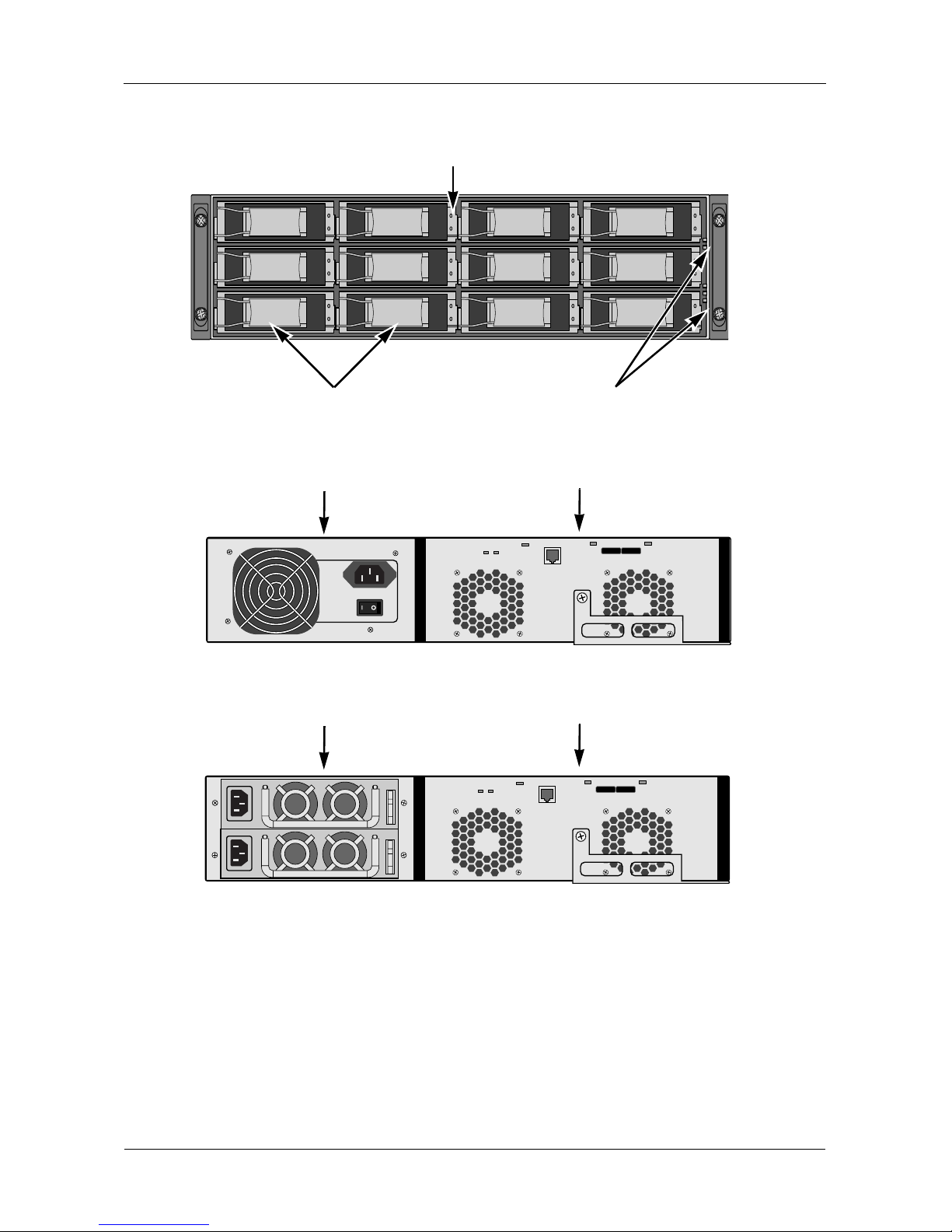
Important data protection information
You should back up all data before installing any drive controller or storage
peripheral. Promise Technology is not responsible for any loss of data resulting
from the use, disuse or misuse of this or any other Promise Technology product.
Notice
Although Promise Technology has attempted to ensure the accuracy of the
content of this manual, it is possible that this document may contain technical
inaccuracies, typographical, or other errors. Promise Technology assumes no
liability for any e rror in thi s p ubl ic ati on, an d fo r damages, whether direct, in dire ct,
incidenta l, c ons eq uen tia l or othe rw is e, t hat m ay res ul t fro m suc h error, including ,
but not limited to loss of data or profits.
Promise Technology provides th is publicat ion “as is ” without w arranty of any kind,
either express or implied, including, but not limited to implied warranties of
merchantability or fitness for a particular purpose.
The published information in the manual is subject to change without notice.
Promise Technology reserves the right to make changes in the product design,
layout, and driver revisions without notification to its users.
This version of the Product Manual supersedes all previous versions.
Recommendations
In this Product Manua l , the appearance of products made by other companies,
including bu t not lim ited to sof tware, serve rs, and d isk driv es, is f or the purp ose of
illustration and explanation only. Promise Technology does not recommend,
endorse, prefer, or support any product made by another manufacturer.

iii
Contents
Chapter 1: Introduction to VessJBOD . . . . . . . . . . . . . . . . . . . . . . . . .1
About This Manual . . . . . . . . . . . . . . . . . . . . . . . . . . . . . . . . . . . . . . .1
VessJBOD Overview . . . . . . . . . . . . . . . . . . . . . . . . . . . . . . . . . . . . .2
Architectural Description . . . . . . . . . . . . . . . . . . . . . . . . . . . . . . . . . .3
Features . . . . . . . . . . . . . . . . . . . . . . . . . . . . . . . . . . . . . . . . . . . . . .3
Specifications . . . . . . . . . . . . . . . . . . . . . . . . . . . . . . . . . . . . . . . . . .3
Power Supply . . . . . . . . . . . . . . . . . . . . . . . . . . . . . . . . . . . . . . .3
Current (maximum) . . . . . . . . . . . . . . . . . . . . . . . . . . . . . . . . . . .4
Power Consumption . . . . . . . . . . . . . . . . . . . . . . . . . . . . . . . . . .4
Temperature . . . . . . . . . . . . . . . . . . . . . . . . . . . . . . . . . . . . . . . .4
Relative Humidity . . . . . . . . . . . . . . . . . . . . . . . . . . . . . . . . . . . .4
Vibration . . . . . . . . . . . . . . . . . . . . . . . . . . . . . . . . . . . . . . . . . . .4
Dimensions (H x W x D) . . . . . . . . . . . . . . . . . . . . . . . . . . . . . . .4
Net Weight . . . . . . . . . . . . . . . . . . . . . . . . . . . . . . . . . . . . . . . . .4
Carton Dimensions (H x W x D) . . . . . . . . . . . . . . . . . . . . . . . . .5
Carton Weight . . . . . . . . . . . . . . . . . . . . . . . . . . . . . . . . . . . . . . .5
Safety . . . . . . . . . . . . . . . . . . . . . . . . . . . . . . . . . . . . . . . . . . . . .5
Environmental . . . . . . . . . . . . . . . . . . . . . . . . . . . . . . . . . . . . . . .5
Warranty and Support . . . . . . . . . . . . . . . . . . . . . . . . . . . . . . . . .5
CE Statement . . . . . . . . . . . . . . . . . . . . . . . . . . . . . . . . . . . . . . .5
FCC Statement . . . . . . . . . . . . . . . . . . . . . . . . . . . . . . . . . . . . . .5
KCC Statement . . . . . . . . . . . . . . . . . . . . . . . . . . . . . . . . . . . . . .6
Chapter 2: VessJBOD Installation . . . . . . . . . . . . . . . . . . . . . . . . . . . .7
Unpacking the VessJBOD . . . . . . . . . . . . . . . . . . . . . . . . . . . . . . . . .7
Mounting VessJBOD in a Rack . . . . . . . . . . . . . . . . . . . . . . . . . . . . .9
Installing Disk Drives . . . . . . . . . . . . . . . . . . . . . . . . . . . . . . . . . . . .11
Drive Slot Numbering . . . . . . . . . . . . . . . . . . . . . . . . . . . . . . . .11
Installing Your Disk Drives . . . . . . . . . . . . . . . . . . . . . . . . . . . .12
Making Data and Management Connections . . . . . . . . . . . . . . . . .13
JBOD Expansion to a VessRAID Subsystem . . . . . . . . . . . . . .13
Drive Enclosures for a SuperTrak RAID Controller . . . . . . . . . .15
Setting Up Serial Cable Connections . . . . . . . . . . . . . . . . . . . . . . .17
Connecting the Power . . . . . . . . . . . . . . . . . . . . . . . . . . . . . . . . . . .18
Front Panel LEDs . . . . . . . . . . . . . . . . . . . . . . . . . . . . . . . . . . .18
Disk Drive LEDs . . . . . . . . . . . . . . . . . . . . . . . . . . . . . . . . . . . .18
I/O Module LEDs . . . . . . . . . . . . . . . . . . . . . . . . . . . . . . . . . . . .19
Setting up the Serial Connection . . . . . . . . . . . . . . . . . . . . . . . . . . .20

VessJBOD 1000 Series Product Manual
iv
Chapter 3: Management . . . . . . . . . . . . . . . . . . . . . . . . . . . . . . . . . . .21
Front Panel LEDs . . . . . . . . . . . . . . . . . . . . . . . . . . . . . . . . . . . . . .21
Disk Drive LEDs . . . . . . . . . . . . . . . . . . . . . . . . . . . . . . . . . . . . . . .22
I/O Module LEDs . . . . . . . . . . . . . . . . . . . . . . . . . . . . . . . . . . . . . . .23
CLI Command Set . . . . . . . . . . . . . . . . . . . . . . . . . . . . . . . . . . . . . .24
Cable Command . . . . . . . . . . . . . . . . . . . . . . . . . . . . . . . . . . . .24
Enclosure Command . . . . . . . . . . . . . . . . . . . . . . . . . . . . . . . .25
Factory Default Command . . . . . . . . . . . . . . . . . . . . . . . . . . . .28
Help Command . . . . . . . . . . . . . . . . . . . . . . . . . . . . . . . . . . . . .29
Link Command . . . . . . . . . . . . . . . . . . . . . . . . . . . . . . . . . . . . .29
Route Command . . . . . . . . . . . . . . . . . . . . . . . . . . . . . . . . . . . .33
Uptime Command . . . . . . . . . . . . . . . . . . . . . . . . . . . . . . . . . . .34
VPDR Command . . . . . . . . . . . . . . . . . . . . . . . . . . . . . . . . . . .35
? Command . . . . . . . . . . . . . . . . . . . . . . . . . . . . . . . . . . . . . . .35
Chapter 4: Maintenance . . . . . . . . . . . . . . . . . . . . . . . . . . . . . . . . . . .37
Updating the Firmware . . . . . . . . . . . . . . . . . . . . . . . . . . . . . . . . . .37
Downloading the Firmware Image File . . . . . . . . . . . . . . . . . . .37
Updating Firmware in WebPAM PROe . . . . . . . . . . . . . . . . . . .37
Updating Firmware with the JBOD Flash Utility . . . . . . . . . . . .39
Replacing a Power Supply . . . . . . . . . . . . . . . . . . . . . . . . . . . . . . .40
VessJBOD 1730 and 1740 . . . . . . . . . . . . . . . . . . . . . . . . . . . .40
VessJBOD 1830 and 1840 . . . . . . . . . . . . . . . . . . . . . . . . . . . .40
Replacing an I/O Module . . . . . . . . . . . . . . . . . . . . . . . . . . . . . . . . .41
Removing the old I/O module . . . . . . . . . . . . . . . . . . . . . . . . . .41
Installing the new I/O module . . . . . . . . . . . . . . . . . . . . . . . . . .42
Replacing a Cooling Fan . . . . . . . . . . . . . . . . . . . . . . . . . . . . . . . . .42
Chapter 5: Support . . . . . . . . . . . . . . . . . . . . . . . . . . . . . . . . . . . . . . .45
Frequently Asked Questions . . . . . . . . . . . . . . . . . . . . . . . . . . . . . .45
Contacting Technical Support . . . . . . . . . . . . . . . . . . . . . . . . . . . . .46
Limited Warranty . . . . . . . . . . . . . . . . . . . . . . . . . . . . . . . . . . . . . . .49
Returning the Product For Repair . . . . . . . . . . . . . . . . . . . . . . . . . .51
Index. . . . . . . . . . . . . . . . . . . . . . . . . . . . . . . . . . . . . . . . . . . . . . . . . . . .53

1
Chapter 1: Introduction to VessJBOD
This chapter covers the following topics:
• About This Manual (below)
• VessJBOD Overview (page 2)
• Architectural Description (page 3)
• Features (page 3)
• Specifications (page 3)
About This Manual
This Product Manual describes how to setup, use, and maintain the VessJBOD
1730, 1740, 1830, and 1840 external disk array subsystems. It also describes
how to use the built-in command-line interface (CLI).
This manual includes a full table of contents, index, chapter task lists, and
numerous cross-references to help you find the specific information you are
looking for.
Also included are four levels of notices:
Note
A Note provides helpful information such as hints or alternative
ways of doing a task.
Important
An Important calls attention to an essential step or point required
to complete a task. Important items include things often missed.
Caution
A Caution informs you of possible equipment damage or loss of
data and how to avoid them.
Warning
A Warning notifies you of probable equipment damage or loss of
data, or the possibility of physical injury, and how to avoid them.
VessJBOD 1000 Series Product Manual
2
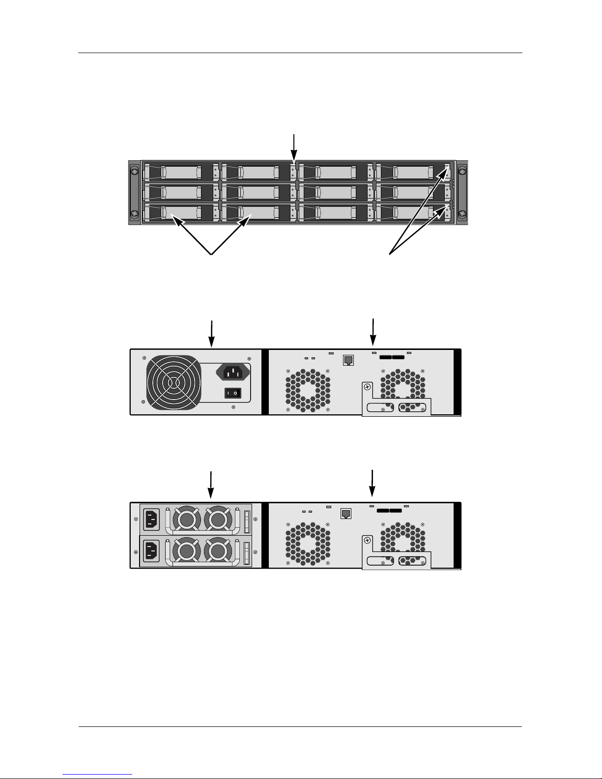
VessJBOD Overview
Figure 1. VessJBOD front view
Figure 2. VessJBOD 1730 rear view
Figure 3. VessJBOD 1830 rear view
Drive Carrier LEDs
Drive Carriers Power and Status LEDs
I/O Module
Power Supply
I/O Module
Power Supplies

Chapter 1: Introduction to VessJBOD
3
Architectural Description
The VessJBOD 1730, 1740, 1830, and 1840 are Serial Attached SCSI (SAS)
subsystems designed for JBOD expansion to a SAS-capable host system.
The VessJBOD subsystems support:
• 3.0 Gb/s SATA disk drives
• 3.0 Gb/s SAS disk drives
All VessJBOD enclosures include a mid-plane, power supply unit, and enclosure
processor all in one cable-less chassis design. Multiple fans and optional power
supplies provide redundancy to ensure continued usage during component
failure.
Features
• RJ11 serial port supports RS232 protocol via adapter cable.
• 12 hot-swappable drive bays in a robust 2U rackmount chassis.
• 16 hot-swappable drive bays in a robust 3U rackmount chassis.
• Redundant, hot-swappable power supplies on 1830 and 1840 models.
• Drive Support: Up to 16 3.5" x 1" SAS or SATA 3 Gb/s hard disk drives.
• Supports any combination of SAS and SATA drives in the system.
• Staggered phys ical drive spin-up.
• Command Line Interface via RJ-11 Serial Port.
• Three years complete system limited warranty includes 24 x 7 email and
phone support w ith hig hl y ex pe rien ce d tec hn ic al s upp ort technicians and an
advanced replac em ents program.
• Compatible with leading SAS hard drives, host bus adapters, and RAID
controllers.
Specifications
Power Supply
1840: 450W, Dual hot-swappable and redundant, 100-240 VAC auto-ranging, 5060 Hz, with PFC
1830: 350W, Dual hot-swappable and redundant, 100-240 VAC auto-ranging, 5060 Hz, with PFC
1740: 450W, Single, 100-240 VAC auto-ranging, 50-60 Hz, with PFC and
80PLUS certification

VessJBOD 1000 Series Product Manual
4
1730: 350W, Single, 100-240 VAC auto-ranging, 50-60 Hz, with PFC and
80PLUS certification
Current (maximum)
1840: 8 A @ 100 VAC or 4 A @ 240 VAC current rating with two power cords
1830: 6A @ 100 VAC or 3 A @ 240 VAC Current rating with two power cords
1740: 7A @ 100 VAC or 3.5 A @ 240 VAC Current rating with one power cord
1730: 6A @ 100 VAC or 3 A @ 240 VAC Current rating with one power cord
Power Consumption
1740, 1840: without disk drives, 72.2 W; with disk drives, 242.3 W
1730, 1830: without disk drives, 80.3 W; with disk drives, 233.4 W
Temperature
Normal conditions:
5° to 40°C operational (-40° to 60°C non-operational)
Conditions of running SAS disk drives with one failed cooling fan:
5° to 35°C operational (-40° to 60°C non-operational)
Relative Humidity
95 percen t maximum
Vibration
Random, 0.21 grms, 5-500 Hz, 30 Mins, X, Y, Z axis.
Dimensions (H x W x D)
1840, 1740: 13 x 45 x 46 cm (5.1 x 17.7 x 18.1 in)
1830, 1730: 8.8 x 45 x 46 cm (3.5 x 17.7 x 18.1 in)
Net Weight
1840: 15.8 kg (34.8 lb) without drives, 23.8 kg (52.5 lb) with 16 drives*
1830: 12.6 kg (27.8 lb) without drives, 18.6 kg (41.0 lb) with 12 drives*
1740: 13.8 kg (30.4 lb) without drives, 21.8 kg (48.1 lb) with 16 drives*
1730: 10.8 kg (23.5 lb) without drives, 16.8 kg (37.1 lb) with 12 drives*
* Assuming 0.5 kg (1.1 lb) per drive.

Chapter 1: Introduction to VessJBOD
5
Carton Dimensions (H x W x D)
All models: 28.5 x 57.2 x 75.2 cm (11.2 x 22.5 x 29.6 in)
Carton Weight
1840: 20.8 kg (45.9 lb)
1830: 18.0 kg (38.8 lb)
1740: 19.2 kg (42.3 lb)
1730: 16.2 kg (35.7 lb)
Safety
BSMI, CB, CCC, CE, FCC Class B, MIC, VCCI, UL, cUL, TUV.
Environmental
RoHS, China RoHS.
Wa rranty and Support
Warranty: Three year limited warranty on all components except the optional
battery backup unit, which has a one-yea r warranty.
Support: 24x7 email and phone support (English only). 24x7 access to Promise
support site for drivers, firmware, and compatibility.
CE Statement
Warning: This is a class B product. In a domestic environment this product may
cause radio interference in which case the user may be required to take
adequate measures.
FCC Statement
This device complies with Part 15 of the FCC Rules. Operation is subject to the
following two conditions: (1) this device may not cause harmful interference, and
(2) this device must accept any interference received, including interference that
may cause undesired operation.

VessJBOD 1000 Series Product Manual
6
KCC Statement
7
Chapter 2: VessJBOD Installation
This chapter covers the following topics:
• Unpacking the Vess JBOD (below)
• Mounting VessJBOD in a Rack (page 9)
• Installing Disk Drives (page 11)
• Making Data and Management Connections (page 13)
• Setti ng Up Serial Cabl e Connections (page 17)
• Connecting the Power (p ag e 18)
• Setting up the Serial Connection (page 20)
Unpacking the VessJBOD
The VessJBOD box contains the following items:
•VessJBOD Unit
• Quick Start Guide printed
• RJ11-to-DB9 serial data cable
• Screws for disk drives
(70 pieces for 16-bay, 50 pieces
for 12-bay)
• 1.5m (4.9 ft) Power cords
(1700 models, 1; 1800 models, 2)
•CD with Product Manual and Quick
Start Guide in PDF format
Warning
The electronic components within the VessJBOD enclosure are
sensitive to damage from Electro-Static Discharge (ESD).
Observe appropriate precautions at all times when handling the
VessJBOD or its subassemblies.
VessJBOD Models and Descriptions
1800
Model
Drive
Slots
Power
Supplies
1700
Model
Drive
Slots
Power
Supplies
1840 16 2 1740 16 1
1830 12 2 1730 12 1
VessJBOD 1000 Series Product Manual
8
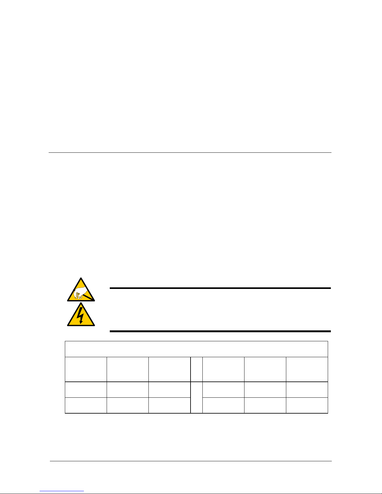
Figure 1. VessJBOD front view
Figure 2. VessJBOD 1730 rear view
Figure 3. VessJBOD 1830 rear view
For a description of the LEDs, see pages 18 and 19.
Drive Carrier LEDs
Drive Carriers Power and Status LEDs
I/O Module
Power Supply
I/O Module
Power Supplies
Chapter 2: VessJBOD Installation
9
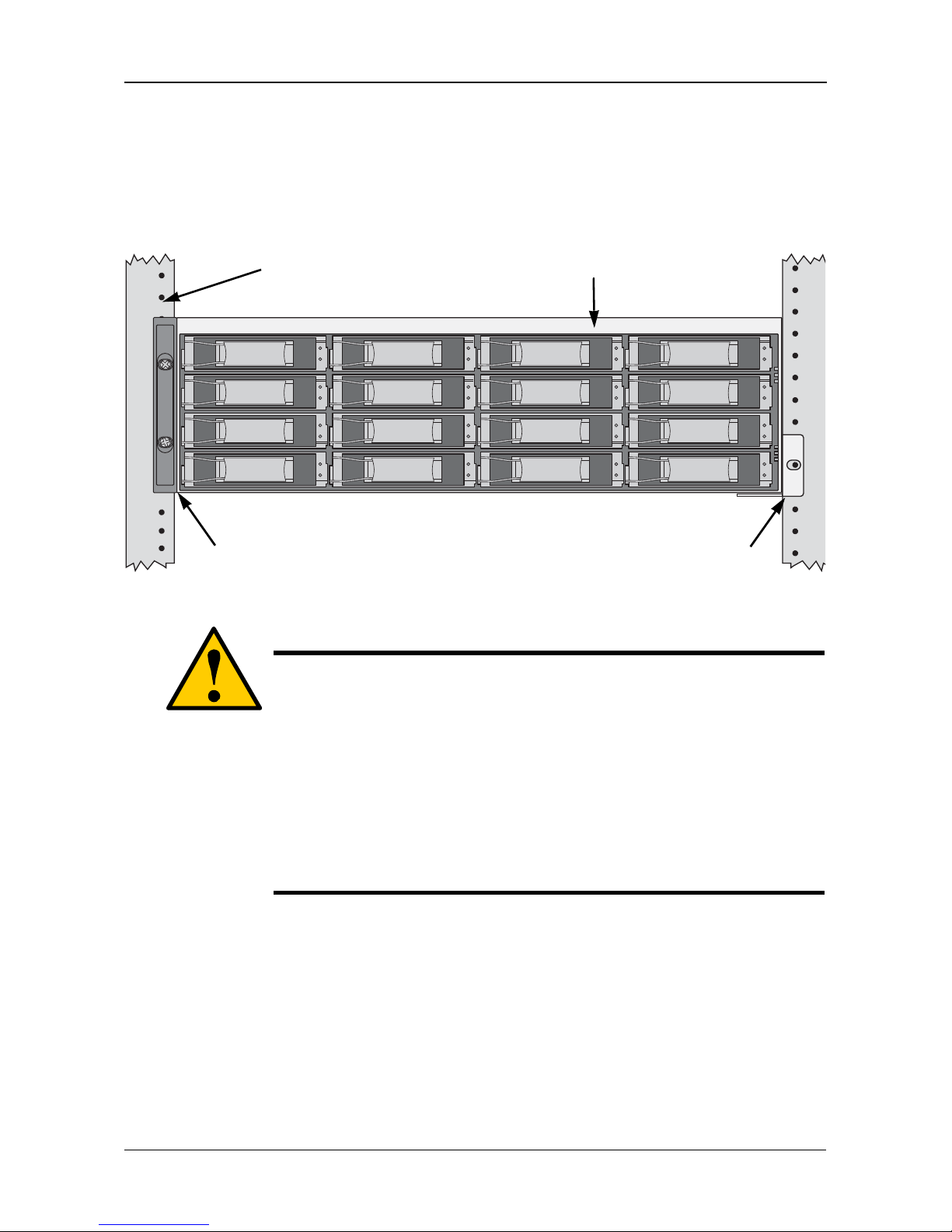
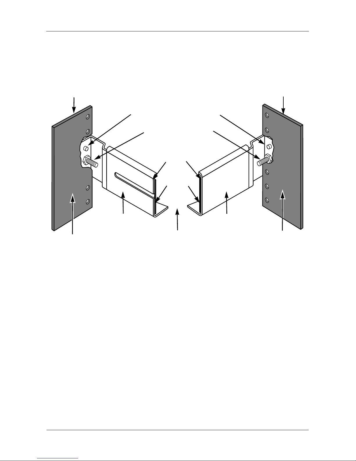
Mounting VessJBOD in a Rack
The VessJBOD subsystem installs to the rack using the available m oun tin g rail s.
You can also use your existing rails.
Figure 4. VessJBOD mounted in a rack with the available rails
To install the VessJBOD subsystem into a rack with the available mounting rails:
1. Check the fit of the mounting rails in your rack system.
2. Adjust the length of the mounting rails as needed.
3. Attach the mounting rail assemblies to the outside of the rack posts, using
the attaching screws from your rack system.
Be sure the support is on the bottom facing inward.
4. Square the rail assemblies in the rack.
5. Tighten the adjustment screws and the attaching screws.
Cautions
• At least two persons are required to safely lift, place, and
attach the VessJBOD subsystem into a rack system.
• Do not lift or mov e the VessJBOD subsys te m by the handles,
power supply or the I/O module. Hold the subsystem itself.
• Only a qualified electrician who is familiar with the installation
procedure should mount and install the VessJBOD
subsystem.
• Be sure all switches are OFF before installing the VessJBOD
subsystem or ex changing components.
V e r tic al Ra ck Post VessJBOD subsystem
Mounting rails mount
outside the rack post
Handles mount
outside the rack post
VessJBOD 1000 Series Product Manual
10
6. Place the VessJBOD subsystem onto the rails.
7. Secure the VessJBOD subsy stem to the rack through each h andle, us ing the
attaching screws from your rack system.
Figure 5. Rack mount assembly diagram
This completes rack mounting. Go to “Installing Disk Drives” on page 11.
Inside of post
Rack front post
Rail attach ing screws
(not included)
Rail adjustment screw
(center, outside of rail)
Flange
Inside of post
Rack back post
Front rail
Rear rail
Support
Locating pins (2 on each end)
Chapter 2: VessJBOD Installation
11
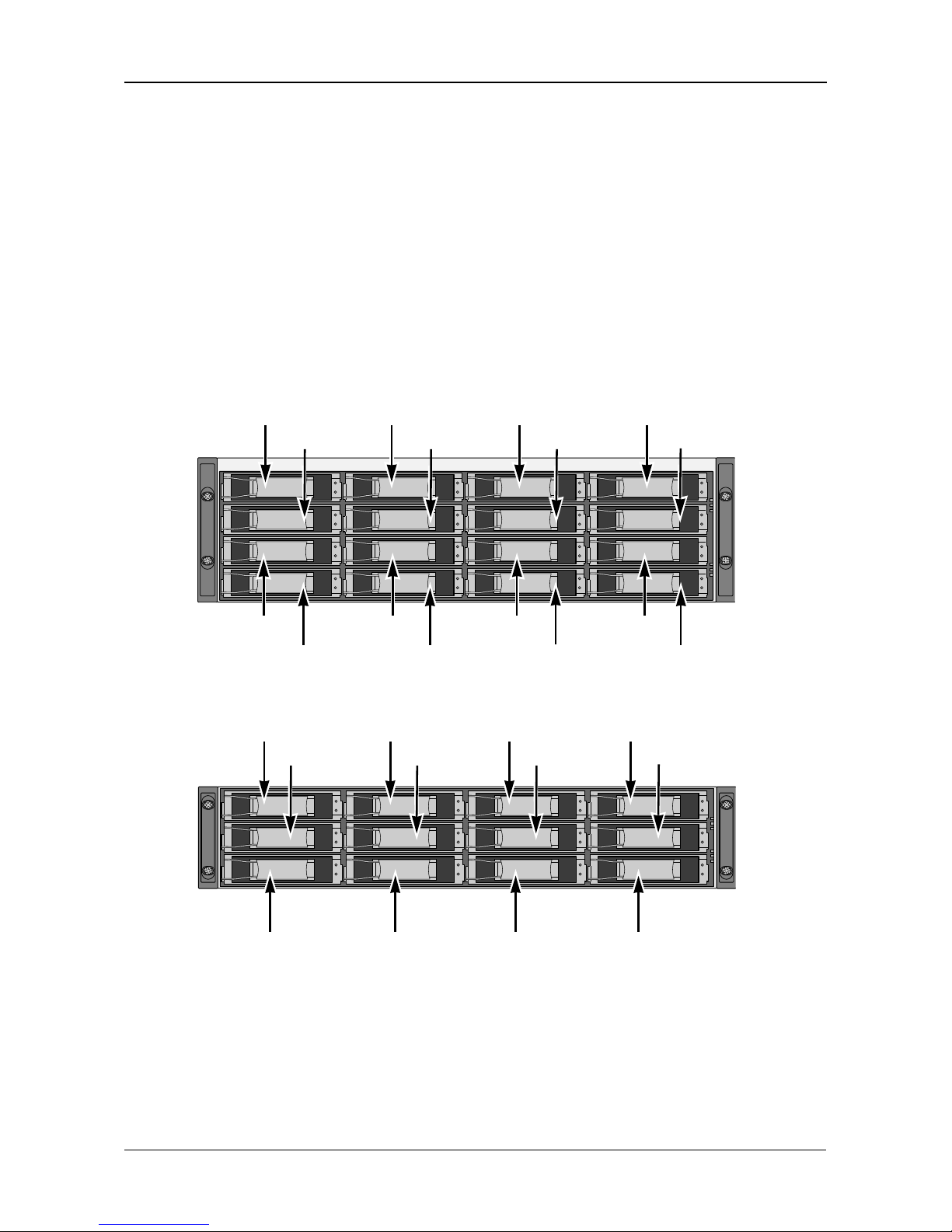
Installing Disk Drives
You can populate the VessJBOD with SAS or SATA ha rd di sk dri ves. Fo r opti ma l
performance, install physical drives of the same model and capacity.
Drive Slot Numbering
You can install any suitable disk drive into any slot in the enclosure. The
diagrams below show how VessJBOD’s drive slots are numbered.
Slot numbering is reflect ed in the W eb PAM PROe and CLU user i nterfac es when
used with a VessRAID subsystem.
Figure 6. VessJBOD drive slot numbering
Figure 7. VessRAID 1730 and 1830 drive slot numbering
Install all of the drive carriers into the VessJBOD enclosure to ensure proper
airflow, even if you do not populate all the carriers with disk drives.
8
65
1234
7
13
14
15
16
9101112
8
65
1234
7
9101112
VessJBOD 1000 Series Product Manual
12
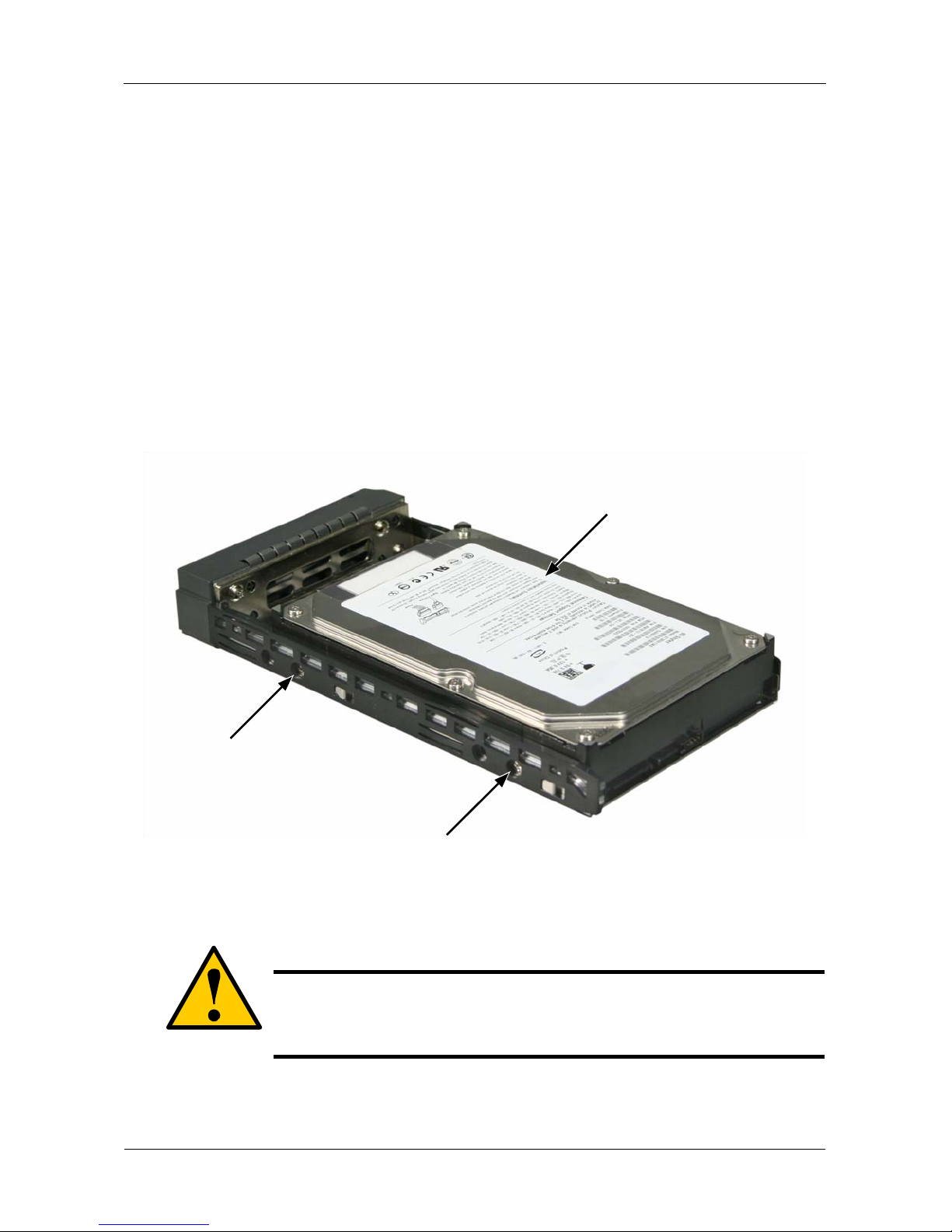
Installing Your Disk Drives
1. Remove a disk drive carrier.
2. Carefully lay the disk drive into the drive carrier at the front, so that the screw
holes on the sides line up.
3. Insert the screws through the holes in the drive carrier and into the sides of
the disk drive.
• Install only the counter-sink screws supplied with the VessJBOD.
• Install four screws per drive.
• Snug each screw. Be careful not to over-tighten.
4. Reinstall the drive carrier into the VessJBOD chassis.
Repeat steps 1 through 3 until all of your disk drives are installed.
Figure 8. Disk drive mounted in a drive carrier
This completes disk drive installation. Go to “Making Data and Management
Connections” on page 13.
Caution
V es sJB OD sup ports disk drive hot-swapping. To avoid hand
contact with an electrical hazard, do not remove more than one
drive carrier a time.
Disk drive
mounting screw
mounting screw

Chapter 2: VessJBOD Installation
13
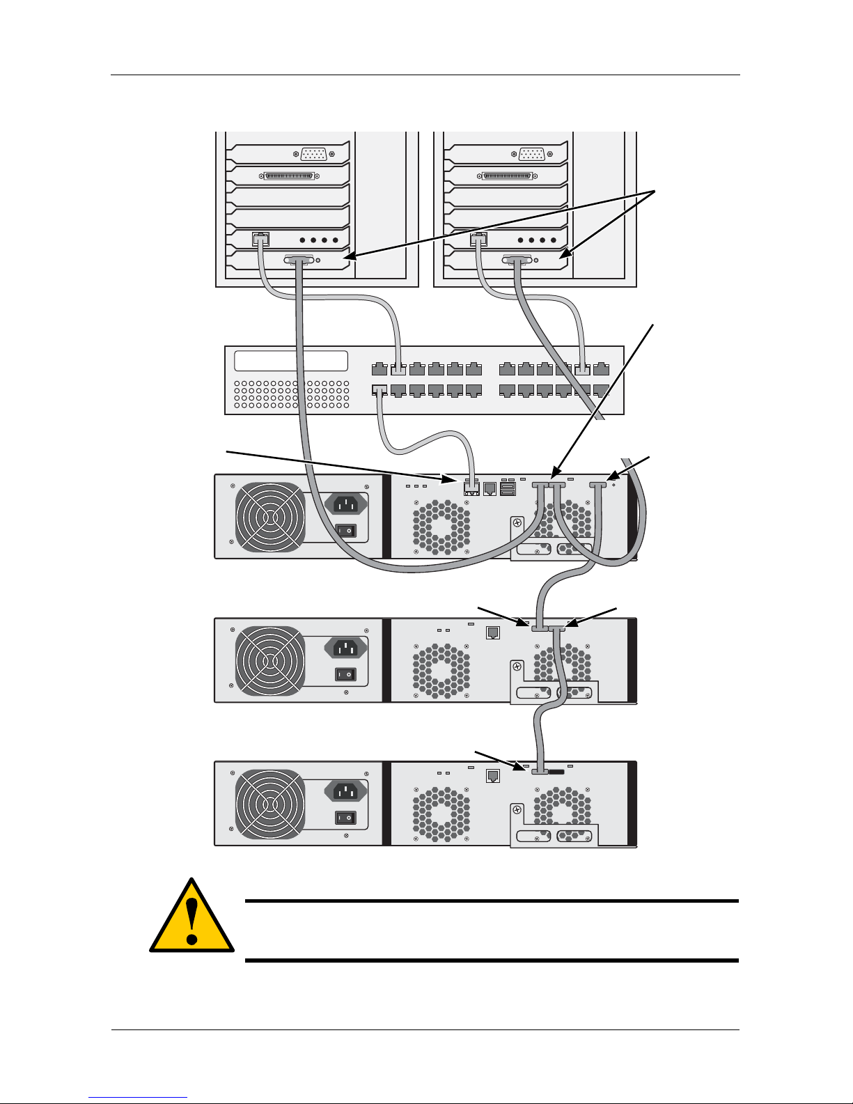
Making Data a nd Management Connections
You can configure your VessJBOD as:
• JBOD Expansion to a VessRAID subsystem
• Drive enclosures for a SuperTrak RAID controller
JBOD Expansion to a VessRAID Subsystem
Configuring a Data Path
To establish the data path:
1. Connect the SAS or iSCSI HBA card in the Host PC to the SAS IN ports or
the iSCSI ports on the VessRAID controller. See page 14, Figure 9.
2. Connect the SAS Expansion port (with a diamond icon) of the VessRAID
controller to the SAS IN p ort (with a circle icon) on the I/O module of the firs t
VessJBOD.
3. Connect the SAS OUT port (with a diamond icon) of the VessJBOD I/O
module of the first VessJBOD to the SAS IN port (with a circle icon) on the
I/O module of the second VessJBOD.
4. Connect the remaining VessJBOD units in the same manner.
Be sure to connect circle icon to diamond icon and vice versa.
All SAS ports have SFF-8088 connectors.
Configuring a Management Path
V e ss RA ID su bs ys tem s ha ve one RAID controller. The c ontr oller has an Ethernet
(RJ45) Management Port connector that enables you to monitor the VessJBOD
subsystems over your network using the WebPAM PROe software.
To establish the management path:
1. Connect the Mana gemen t port on each VessRAID contro ller to y our netwo rk
switch. See Figure 9.
2. Connect the Host PC’s or Server’s NIC to your network switch.
Direct Management of VessJBOD
A management connection directly to the VessJBOD uses a serial connection to
the Host PC. See pages 17 and 20 for more information.
VessJBOD 1000 Series Product Manual
14
Figure 9. Data and management connections with VessRAID
This completes data and management connections. Go to “Setting Up Serial
Cable Connections” on page 17.
Caution
Make data conn ections carefully. If you accidently switch a SAS IN
connection with a SAS OUT, the RAID system cannot function.
Host PCs or
Servers
SAS HBA
cards
Network
Switch
VessRAID
VessJBOD
SAS Expansion por
t
diamond icon
VessJBOD
SAS OUT port
diamond icon
SAS IN port
s
circle icon
SAS IN port
circle icon
SAS IN port
circle icon
Management Port
 Loading...