

Page 1

F
AST
TX4650, TX2650
U
SER
T
M
Version 1.0
ANUAL
RAK
Page 2

FastTrak TX4650, TX2650 User Manual
Copyright
© 2007 Promise Technology, Inc. All Rights Reserved.
Copyright by Promise Technology, Inc. (Promise Technology). No part of this
manual may be reproduced or transmitted in any form without the expressed,
written permission of Promise Technology.
Trademarks
Promise and the Promise logo are registered in U.S. Patent and Trademark
Office. All other product names mentioned herein may be trademarks or
registered trademarks of their respective companies.
Important data protection information
You should back up all data before installing any drive controller or storage
peripheral. Promise Technology is not responsible for any loss of data resulting
from the use, disuse or misuse of this or any other Promise Technology product.
Notice
Although Promise Technology has attempted to ensure the accuracy of the
content of this manual, it is possible that this document may contain technical
inaccuracies, typographical, or other errors. Promise Technology assumes no
liability for any error in this publication, and for damages, whether direct, indirect,
incidental, consequential or otherwise, that may result from such error, including,
but not limited to loss of data or profits.
Promise Technology provides this publication “as is” without warranty of any
kind, either express or implied, including, but not limited to implied warranties of
merchantability or fitness for a particular purpose.
The published information in the manual is subject to change without notice.
Promise Technology reserves the right to make changes in the product design,
layout, and driver revisions without notification to its users.
This version of the User Manual supersedes all previous versions.
Recommendations
The appearance in this manual of products made by other companies, including,
but not limited to, software, servers, and physical (disk) drives, is for the purpose
of illustration and explanation only. Promise Technology does not recommend,
endorse, prefer, or support any product made by another manufacturer.
ii
Page 3

Contents
Chapter 1: Introduction . . . . . . . . . . . . . . . . . . . . . . . . . . . . . . . . . . . . .1
About This Manual . . . . . . . . . . . . . . . . . . . . . . . . . . . . . . . . . . . . . . .1
Overview . . . . . . . . . . . . . . . . . . . . . . . . . . . . . . . . . . . . . . . . . . . . . .2
FastTrak TX Series . . . . . . . . . . . . . . . . . . . . . . . . . . . . . . . . . . . . . .2
FastTrak TX4650 . . . . . . . . . . . . . . . . . . . . . . . . . . . . . . . . . . . .2
FastTrak TX2650 . . . . . . . . . . . . . . . . . . . . . . . . . . . . . . . . . . . .2
WebPAM Software . . . . . . . . . . . . . . . . . . . . . . . . . . . . . . . . . . . . . .3
Key Features and Benefits . . . . . . . . . . . . . . . . . . . . . . . . . . . . . . . .4
Specifications . . . . . . . . . . . . . . . . . . . . . . . . . . . . . . . . . . . . . . . . . .6
Chapter 2: Installation . . . . . . . . . . . . . . . . . . . . . . . . . . . . . . . . . . . . . .7
Unpacking Your FastTrak Card . . . . . . . . . . . . . . . . . . . . . . . . . . . . .7
Installing the FastTrak Card . . . . . . . . . . . . . . . . . . . . . . . . . . . . . . .8
Connecting the FastTrak Card . . . . . . . . . . . . . . . . . . . . . . . . . . . .10
Using a SuperSwap Enclosure . . . . . . . . . . . . . . . . . . . . . . . . .10
Without a SuperSwap Enclosure . . . . . . . . . . . . . . . . . . . . . . .11
Creating Your Logical Drive . . . . . . . . . . . . . . . . . . . . . . . . . . . . . . .12
Installing WebPAM . . . . . . . . . . . . . . . . . . . . . . . . . . . . . . . . . . . . .15
Utility Server . . . . . . . . . . . . . . . . . . . . . . . . . . . . . . . . . . . . . . .15
Java Runtime Environment . . . . . . . . . . . . . . . . . . . . . . . . . . . .16
Operating System Support . . . . . . . . . . . . . . . . . . . . . . . . . . . .16
Browser Support . . . . . . . . . . . . . . . . . . . . . . . . . . . . . . . . . . . .16
Installation . . . . . . . . . . . . . . . . . . . . . . . . . . . . . . . . . . . . . . . . .16
Chapter 3: Installing Drivers . . . . . . . . . . . . . . . . . . . . . . . . . . . . . . . .23
FastTrak Driver Diskette for Windows . . . . . . . . . . . . . . . . . . . . . . .24
USB Memory Stick for Windows . . . . . . . . . . . . . . . . . . . . . . . . . . .24
FastTrak Driver Diskette for Linux . . . . . . . . . . . . . . . . . . . . . . . . . .25
Windows Vista . . . . . . . . . . . . . . . . . . . . . . . . . . . . . . . . . . . . . . . . .26
New OS Installation . . . . . . . . . . . . . . . . . . . . . . . . . . . . . . . . .26
Existing System . . . . . . . . . . . . . . . . . . . . . . . . . . . . . . . . . . . .27
Confirming Driver Installation . . . . . . . . . . . . . . . . . . . . . . . . . .27
Windows Server 2003 . . . . . . . . . . . . . . . . . . . . . . . . . . . . . . . . . . .28
New OS Installation . . . . . . . . . . . . . . . . . . . . . . . . . . . . . . . . .28
Existing System . . . . . . . . . . . . . . . . . . . . . . . . . . . . . . . . . . . .29
Confirming Driver Installation . . . . . . . . . . . . . . . . . . . . . . . . . .29
Windows XP . . . . . . . . . . . . . . . . . . . . . . . . . . . . . . . . . . . . . . . . . .30
New OS Installation . . . . . . . . . . . . . . . . . . . . . . . . . . . . . . . . .30
Existing System . . . . . . . . . . . . . . . . . . . . . . . . . . . . . . . . . . . .31
Confirming Driver Installation . . . . . . . . . . . . . . . . . . . . . . . . . .31
iii
Page 4

FastTrak TX4650, TX2650 User Manual
Chapter 3: Installing Drivers, cont.
Windows 2000 . . . . . . . . . . . . . . . . . . . . . . . . . . . . . . . . . . . . . . . . .32
New OS Installation . . . . . . . . . . . . . . . . . . . . . . . . . . . . . . . . .32
Existing System . . . . . . . . . . . . . . . . . . . . . . . . . . . . . . . . . . . .33
Confirming Driver Installation . . . . . . . . . . . . . . . . . . . . . . . . . .33
Red Hat Linux Enterprise 5.0 . . . . . . . . . . . . . . . . . . . . . . . . . . . . .34
New OS Installation . . . . . . . . . . . . . . . . . . . . . . . . . . . . . . . . .34
Existing System . . . . . . . . . . . . . . . . . . . . . . . . . . . . . . . . . . . .34
SuSE Linux Enterprise Server 10.0 . . . . . . . . . . . . . . . . . . . . . . . . .35
New OS Installation . . . . . . . . . . . . . . . . . . . . . . . . . . . . . . . . .35
Existing System . . . . . . . . . . . . . . . . . . . . . . . . . . . . . . . . . . . .35
Chapter 4: FastBuild™ Utility . . . . . . . . . . . . . . . . . . . . . . . . . . . . . . .37
Using the FastTrak BIOS . . . . . . . . . . . . . . . . . . . . . . . . . . . . . . . . .37
Navigating the Main Menu . . . . . . . . . . . . . . . . . . . . . . . . . . . . . . . .38
Viewing Drive Assignments . . . . . . . . . . . . . . . . . . . . . . . . . . . . . . .39
Creating a Logical Drive . . . . . . . . . . . . . . . . . . . . . . . . . . . . . . . . .40
Creating Two Logical Drives . . . . . . . . . . . . . . . . . . . . . . . . . . . . . .43
Deleting a Logical Drive . . . . . . . . . . . . . . . . . . . . . . . . . . . . . . . . . .49
Viewing the Controller Configuration . . . . . . . . . . . . . . . . . . . . . . . .51
Responding to Logical Drive Problems . . . . . . . . . . . . . . . . . . . . . .52
Finding a Failed Drive in FastBuild . . . . . . . . . . . . . . . . . . . . . .52
Chapter 5: WebPAM . . . . . . . . . . . . . . . . . . . . . . . . . . . . . . . . . . . . . . .53
Logging into WebPAM . . . . . . . . . . . . . . . . . . . . . . . . . . . . . . . . . . .53
Regular Connection . . . . . . . . . . . . . . . . . . . . . . . . . . . . . . . . .53
Secure Connection . . . . . . . . . . . . . . . . . . . . . . . . . . . . . . . . . .53
Logging out of WebPAM . . . . . . . . . . . . . . . . . . . . . . . . . . . . . . . . .55
Managing Users . . . . . . . . . . . . . . . . . . . . . . . . . . . . . . . . . . . . . . .56
Adding a User . . . . . . . . . . . . . . . . . . . . . . . . . . . . . . . . . . . . . .56
Setting Event Notification . . . . . . . . . . . . . . . . . . . . . . . . . . . . .57
Setting a Net Send IP Address . . . . . . . . . . . . . . . . . . . . . . . . .60
Deleting a User . . . . . . . . . . . . . . . . . . . . . . . . . . . . . . . . . . . . .61
Changing a User’s Password . . . . . . . . . . . . . . . . . . . . . . . . . .61
Changing a User’s Email Address . . . . . . . . . . . . . . . . . . . . . .63
Changing a User’s Access Rights . . . . . . . . . . . . . . . . . . . . . . .63
Viewing Host Management . . . . . . . . . . . . . . . . . . . . . . . . . . . . . . .65
Making Utility Configuration Settings . . . . . . . . . . . . . . . . . . . . . . . .66
Viewing the FastTrak Card . . . . . . . . . . . . . . . . . . . . . . . . . . . . . . .67
iv
Page 5

Chapter 5: WebPAM, cont.
Managing the Controller . . . . . . . . . . . . . . . . . . . . . . . . . . . . . . . . .68
Viewing Controller Information . . . . . . . . . . . . . . . . . . . . . . . . .68
Making Controller Settings . . . . . . . . . . . . . . . . . . . . . . . . . . . .68
Viewing Scheduled Actions . . . . . . . . . . . . . . . . . . . . . . . . . . . .70
Deleting a Scheduled Action . . . . . . . . . . . . . . . . . . . . . . . . . . .70
Locking the Controller . . . . . . . . . . . . . . . . . . . . . . . . . . . . . . . .71
Restoring Default Settings . . . . . . . . . . . . . . . . . . . . . . . . . . . .72
Managing Physical Drives . . . . . . . . . . . . . . . . . . . . . . . . . . . . . . . .73
Viewing Physical Drives . . . . . . . . . . . . . . . . . . . . . . . . . . . . . .73
Viewing Physical Drive Information . . . . . . . . . . . . . . . . . . . . . .74
Making Physical Drive Settings . . . . . . . . . . . . . . . . . . . . . . . . .75
Running Media Patrol . . . . . . . . . . . . . . . . . . . . . . . . . . . . . . . .75
Checking the Bad Sector Log . . . . . . . . . . . . . . . . . . . . . . . . . .77
Locating a Physical Drive . . . . . . . . . . . . . . . . . . . . . . . . . . . . .78
Managing Logical Drives . . . . . . . . . . . . . . . . . . . . . . . . . . . . . . . . .80
Viewing All Logical Drives . . . . . . . . . . . . . . . . . . . . . . . . . . . . .80
Creating a Logical Drive . . . . . . . . . . . . . . . . . . . . . . . . . . . . . .80
Creating a JBOD . . . . . . . . . . . . . . . . . . . . . . . . . . . . . . . . . . . .84
Deleting a Logical Drive or JBOD . . . . . . . . . . . . . . . . . . . . . . .88
Viewing Logical Drive Information . . . . . . . . . . . . . . . . . . . . . . .88
Making Logical Drive Settings . . . . . . . . . . . . . . . . . . . . . . . . . .89
Migrating a Logical Drive . . . . . . . . . . . . . . . . . . . . . . . . . . . . .90
Rebuilding a Logical Drive . . . . . . . . . . . . . . . . . . . . . . . . . . . .93
Synchronizing a Logical Drive . . . . . . . . . . . . . . . . . . . . . . . . . .97
Viewing Logical Drive Initialization . . . . . . . . . . . . . . . . . . . . . .99
Activating a Logical Drive . . . . . . . . . . . . . . . . . . . . . . . . . . . .100
Responding to a Critical or Offline Logical Drive . . . . . . . . . .101
Managing Enclosures . . . . . . . . . . . . . . . . . . . . . . . . . . . . . . . . . .105
Viewing Enclosures . . . . . . . . . . . . . . . . . . . . . . . . . . . . . . . . .105
Viewing Enclosure Information . . . . . . . . . . . . . . . . . . . . . . . .105
Managing Spare Drives . . . . . . . . . . . . . . . . . . . . . . . . . . . . . . . . .107
Viewing Spare Drives . . . . . . . . . . . . . . . . . . . . . . . . . . . . . . .107
Creating a Spare Drive . . . . . . . . . . . . . . . . . . . . . . . . . . . . . .107
Deleting a Spare Drive . . . . . . . . . . . . . . . . . . . . . . . . . . . . . .108
Contents
v
Page 6

FastTrak TX4650, TX2650 User Manual
Chapter 6: Technology . . . . . . . . . . . . . . . . . . . . . . . . . . . . . . . . . . .109
About FastTrak . . . . . . . . . . . . . . . . . . . . . . . . . . . . . . . . . . . . . . .109
Adapter BIOS . . . . . . . . . . . . . . . . . . . . . . . . . . . . . . . . . . . . .109
Introduction to RAID . . . . . . . . . . . . . . . . . . . . . . . . . . . . . . . . . . .109
RAID 0 – Stripe . . . . . . . . . . . . . . . . . . . . . . . . . . . . . . . . . . . .110
RAID 1 – Mirror . . . . . . . . . . . . . . . . . . . . . . . . . . . . . . . . . . . .111
RAID 5 – Block Striping with Distributed Parity . . . . . . . . . . . .112
RAID 10 – Mirror / Stripe . . . . . . . . . . . . . . . . . . . . . . . . . . . . .113
JBOD – Single Drive . . . . . . . . . . . . . . . . . . . . . . . . . . . . . . . .115
Choosing a RAID Level . . . . . . . . . . . . . . . . . . . . . . . . . . . . . . . . .116
RAID 0 . . . . . . . . . . . . . . . . . . . . . . . . . . . . . . . . . . . . . . . . . .116
RAID 1 . . . . . . . . . . . . . . . . . . . . . . . . . . . . . . . . . . . . . . . . . .116
RAID 5 . . . . . . . . . . . . . . . . . . . . . . . . . . . . . . . . . . . . . . . . . .117
RAID 10 . . . . . . . . . . . . . . . . . . . . . . . . . . . . . . . . . . . . . . . . .117
JBOD . . . . . . . . . . . . . . . . . . . . . . . . . . . . . . . . . . . . . . . . . . .117
Other Logical Drive Features . . . . . . . . . . . . . . . . . . . . . . . . . . . . .118
Stripe Block Size . . . . . . . . . . . . . . . . . . . . . . . . . . . . . . . . . . .118
Initialization . . . . . . . . . . . . . . . . . . . . . . . . . . . . . . . . . . . . . . .118
Gigabyte Boundary . . . . . . . . . . . . . . . . . . . . . . . . . . . . . . . . .118
Hot Spare Drive . . . . . . . . . . . . . . . . . . . . . . . . . . . . . . . . . . .118
Cache Setting . . . . . . . . . . . . . . . . . . . . . . . . . . . . . . . . . . . . .119
Logical Drive Migration . . . . . . . . . . . . . . . . . . . . . . . . . . . . . .119
Chapter 7: Support . . . . . . . . . . . . . . . . . . . . . . . . . . . . . . . . . . . . . .123
Frequently Asked Questions . . . . . . . . . . . . . . . . . . . . . . . . . . . . .123
Contact Technical Support . . . . . . . . . . . . . . . . . . . . . . . . . . . . . .130
Limited Warranty . . . . . . . . . . . . . . . . . . . . . . . . . . . . . . . . . . . . . .133
Return Product For Repair . . . . . . . . . . . . . . . . . . . . . . . . . . . . . .135
Appendix A: Partition and Format . . . . . . . . . . . . . . . . . . . . . . . . . .137
Appendix B: Upgrades . . . . . . . . . . . . . . . . . . . . . . . . . . . . . . . . . . .141
BIOS and Firmware Upgrade . . . . . . . . . . . . . . . . . . . . . . . . . . . .141
Software Driver Upgrade . . . . . . . . . . . . . . . . . . . . . . . . . . . . . . . .143
WebPAM Upgrade . . . . . . . . . . . . . . . . . . . . . . . . . . . . . . . . . . . . .146
vi
Page 7

Chapter 1: Introduction
• About This Manual, below
• Overview (page 2)
• FastTrak TX Series (page 2)
• WebPAM Software (page 3)
• Key Features and Benefits (page 4)
• Specifications (page 6)
Thank you for purchasing Promise Technology’s FastTrak TX4650 or TX2650
SATA/SAS RAID Controller card.
About This Manual
This User Manual describes how to setup, use and maintain your FastTrak
TX4650 or TX2650 SATA/SAS RAID Controller cards.
This manual includes a full table of contents, chapter task lists and numerous
cross-references to help you find the specific information you are looking for.
Also included are four levels of notices:
Note
A Note provides helpful information such as hints or alternative
ways of doing a task.
Important
An Important calls attention to an essential step or point required
to complete a task. Important items include things often missed.
Caution
A Caution informs you of possible equipment damage or loss of
data and how to avoid them.
Warning
A Warning notifies you of probable equipment damage or loss of
data, or the possibility of physical injury, and how to avoid them.
1
Page 8

FastTrak TX4650, TX2650 User Manual
Overview
The PC which you are using either already contains FastTrak TX4650 or TX2650
card installed by a third-party or you have acquired a FastTrak TX4650 or
TX2650 retail product for your existing PC and plan to install the card yourself.
• For PC owners wishing to install their FastTrak TX4650 or TX2650 card, go
to “Chapter 2: Installation” on page 7.
• For PCs with a FastTrak TX4650 or TX2650 card already installed but the
FastTrak card does not recognize your physical (disk) drives, go to “Chapter
7: Support” on page 123.
• If your operating system has crashed for some reason or you have
downloaded updated drivers from the Promise website http://
www.promise.com/support, you may wish to reinstall software drivers for the
FastTrak TX4650 or TX2650 card. See “Chapter 3: Installing Drivers” on
page 23.
FastTrak TX Series
Promise originally designed the FastTrak TX4650 or TX2650 as cost-effective,
high performance RAID controller cards that add performance and/or reliability to
PC desktops and/or servers using SATA and SAS drives.
FastTrak TX4650
The FastTrak TX4650 has four independent data channels to support up to four
SATA or SAS physical drives and the following RAID levels:
• Stripe (RAID 0) – Identical drives can read and write data in parallel to
increase performance.
• Mirror (RAID 1) – Mirror increases read performance through load balancing
and elevator sorting while creating a complete backup of your files.
• Block Striping with Distributed Parity (RAID 5) – Organizes data and
distributes parity across the physical drives to increase performance and
provide fault tolerance to protect your data.
• Mirror/Stripe (RAID 10) – Combines RAID 0 and RAID 1 to increase
performance by reading and writing data in parallel while protecting data with
duplication.
• JBOD – Just a bunch of disks. Up to four physical drives working
independently.
FastTrak TX2650
The FastTrak TX2650 has two independent data channels to support up to two
SATA or SAS physical drives and the following RAID levels:
2
Page 9

Chapter 1: Introduction
• Stripe (RAID 0) – Identical drives can read and write data in parallel to
increase performance.
• Mirror (RAID 1) – Mirror increases read performance through load balancing
and elevator sorting while creating a complete backup of your files.
• JBOD – Just a bunch of disks. Up to two physical drives working
independently.
A FastTrak TX4650 or TX2650 striped logical drive can double the sustained
data transfer rate of Serial ATA drives.
FastTrak TX4650 and TX2650 offer fault tolerant, data redundancy for entry-level
network file servers or simply for desktop PC users wanting to continually protect
valuable data on their PC.
Should a physical drive in a mirrored logical drive fail, FastTrak TX4650 or
TX2650 use the mirrored drive (which contains identical data) to assume all data
handling. When a replacement physical drive is later installed, FastTrak TX4650
or TX2650 will rebuild the data to the replacement physical drive from the
remaining mirrored drive to restore fault tolerance.
FastTrak TX4650 and TX2650 bootable BIOS supports individual drives larger
than 137 GB. With FAT32 and NTFS partitioning, the logical drive can be
addressed as one large single volume.
WebPAM Software
The Web-based Promise Array Management (WebPAM) RAID management
software offers local management and monitoring of FastTrak logical drives.
Browser-based GUI provides email notification of all major events or alarms,
memory cache management, logging for Windows servers, logical drive
maintenance, rebuild, and access to all related components (server, controller,
data channels, physical drives, and enclosure).
WebPAM also displays messages about critical events on the Host PC’s monitor
screen even if your browser is closed.
For information on using WebPAM, refer to “Chapter 5: WebPAM” on page 53.
3
Page 10

FastTrak TX4650, TX2650 User Manual
Key Features and Benefits
The following information offers an overview of the major features of your new
Promise FastTrak TX4650 and TX2650.
Advanced Hardware Design
Features Benefits
Supports single-lane PCIe
bus motherboards
TX4650 supports: RAID 0,
RAID 1, RAID 5, and RAID 10
TX2650 supports: RAID 0 and
RAID 1
Supports Serial ATA
Specification II
Supports Serial Attached
SCSI Specification
Independent data channels
for SATA and SAS drives
Supports multiple LUNs, two
per physical drive
Supports online logical drive
expansion
Supports online logical drive
migration
Utilizes FastBuild™ automenu
from the FastTrak onboard
BIOS
Displays status and error
checking messages during
bootup
Supports S.M.A.R.T.
monitoring and reporting
Employs the latest Promise
PCI Express SATA/SAS ASIC
technology
Allows maximum data transfers of up to 2.5 Gb/s
in both directions simultaneously to dramatically
reduce the time to save and retrieve large files.
Provides dramatic increase in drive performance
and/or fault tolerant options. Offers performance
customization and data rebuilds from the BIOS
menu.
Burst data transfer rates up to 300 MB/s from
Serial ATA drives to boost overall system
performance.
Burst data transfer rates up to 300 MB/s from
SAS drives to boost overall system
performance.
Drives can multiply their data transfer
performance when striped together and each
drive uses a separate data channel.
TX4650 supports up to 8 logical drives.
TX2650 supports up to 4 logical drives.
Add physical drives to the logical drive without
affecting data availability.
Change RAID level without affecting data
availability.
Has “Auto Setup” option for quick and easy
logical drive builds.
Notifies user of possible errors and allows for
recovery of mirrored drive logical drives directly
from FastBuild™.
Polls status every 15 minutes, reports through
WebPAM.
Fully supports Serial ATA specifications with 150
and 300 MB/sec timing and CRC error-checking
at high speeds.
4
Page 11

Chapter 1: Introduction
Advanced Hardware Design
Features Benefits
Mirror supports automatic
background rebuilds
DOS based flash upgrade of
BIOS
Fault tolerance can be restored automatically
without rebooting.
Verifies proper file, option to backup existing file.
Download files from Promise website.
Gigabyte Boundary Allows easier interchangeability among physical
drive vendors.
System reboot not required
after create, delete, migrate or
System boot process continues without
restarting.
expand logical drive
Compatibility
Features Benefits
Complies with PCIe
®
Base
Provides highest level of hardware compatibility.
Specification 1.1
Complies with SATA
Specification 1.0a
Complies with Serial ATA 2.6
Specification
Tested compatibility to coexist
with motherboards that have
integrated IDE controllers
Compatible with all major
SATA generation 1 and SATA
Provides full compatibility with first generation
SATA hard drives.
Provides enclosure and drive monitoring
compatibility.
Improves system performance and minimizes
system conflicts for new and existing
installations.
Promise performs verification testing with major
drive manufacturers and development partners.
generation 2, phase 1 and
phase 2 physical drives
Features LBA support Supports drives greater than 137 GB capacity.
Supports BIOS Boot
Specification
All logical drives attached to the FastTrak card
appear in the BBS-compliant motherboards
BIOS boot list.
Compatible with Promise
SuperSwap enclosures
Provides enclosure management including fan,
temperature and voltages.
5
Page 12

FastTrak TX4650, TX2650 User Manual
Specifications
• Low-profile printed circuit board
• PCI Express x1 Slot
• Controller card dimensions (H x W): 2.70 x 4.43 inches (68.5 x 112.5 mm)
• Operating temperatures: 32
• Operating humidity: 5% to 95% non-condensing
° to 122°F (0°C to 50°C)
6
Page 13

Chapter 2: Installation
• Unpack Your FastTrak Card (below)
• Installing the FastTrak Card (page 8)
• Connecting the FastTrak Card (page 10)
• Creating Your Logical Drive (page 12)
• Installing WebPAM (page 15)
This Chapter is designed to quickly get your FastTrak TX Series SATA/SAS
RAID Controller card up and running.
If you plan to run the WebPAM software, you must also install the driver
appropriate to your operating system. See “Chapter 3: Installing Drivers” on
page 23.
Unpacking Your FastTrak Card
When you receive the FastTrak TX Series SATA/SAS RAID Controller card, the
package should contain the items listed below:
• FastTrak TX4650 or TX2650 card
• Low profile bracket
• Quick Start Guide
• 0.65 m (26 inch) SATA data to SFF-8482 data/power cables
Four for TX4650, two for TX2650
• CD with Promise RAID Management (WebPAM) software, Windows and
Linux drivers, and FastTrak TX4650, TX2650 User Manual
If any of the items are missing or appear to be damaged, please contact your
dealer or distributor immediately.
Warning
The electronic components on the FastTrak TX4650 or TX2650
card are sensitive to damage from Electro-Static Discharge (ESD).
Observe appropriate precautions at all times when handling the
FastTrak card or its subassemblies.
Warning
Before installing the adapter into an existing system, backup any
important or useful data. Failure to follow this accepted PC
practice could result in data loss.
7
Page 14
FastTrak TX4650, TX2650 User Manual
Note
The FastTrak TX4650 or TX2650 card is a PCI Plug-n-Play (PnP)
device. No changes are necessary in the motherboard CMOS/
BIOS Setup for resources or drive types in most applications.
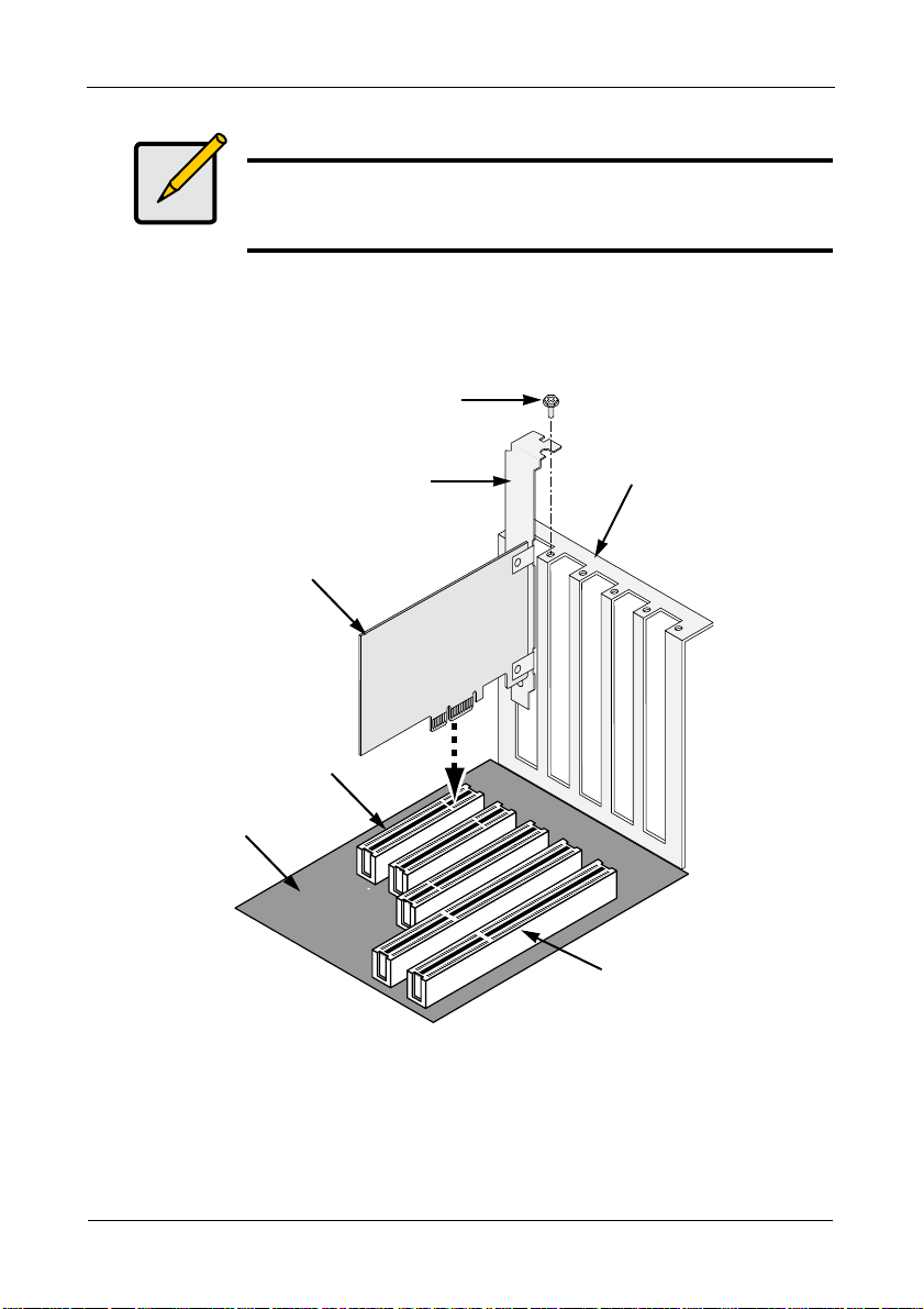
Installing the FastTrak Card
The FastTrak TX4650 or TX2650 card fits into any available PCI-E x1, x4, x8, or
x16 slot in your PC’s motherboard.
Attaching screw
Bracket
FastTrak RAID
Controller card
PCI-E slots
Motherboard
1. Remove the cover of your system.
2. Install the FastTrak TX4650 or TX2650 card into the open PCI-E slot.
3. Fasten the controller card bracket to the system’s frame.
4. Attach your system case’s 2- or 4-pin LED cable to the LED connector on the
FastTrak TX4650 or TX2650 card.
System frame
PCI slots
8
Page 15
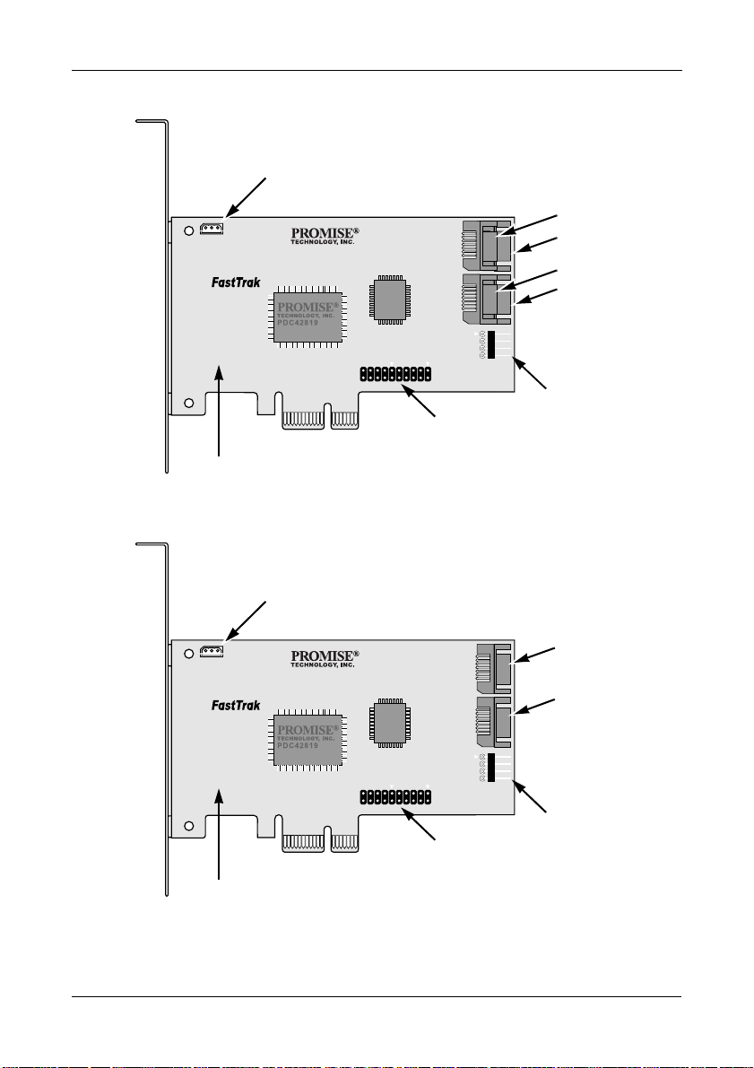
Figure 1. Connectors on the FastTrak TX4650 card
I2C/SMBus Connector
for SuperSwap
Chapter 2: Installation
Port 3
Port 1
TX4650
Individual LED
Connectors
FastTrak TX4650 card
Figure 2. Connectors on the FastTrak TX2650 card
I2C/SMBus Connector
for SuperSwap
TX2650
Port 4
Port 2
Global LED
Connectors
Port 1
Port 2
FastTrak TX2650 card
Global LED
Individual LED
Connectors
Connectors
9
Page 16

FastTrak TX4650, TX2650 User Manual
Connecting the FastTrak Card
The FastTrak TX4650 and TX2650 cards support SATA 1.5Gb/s, SATA 3.0 Gb/s,
and SAS physical (disk) drives. For optimal performance, install drives of the
same model and capacity. The drives’ matched performance allows the logical
drive to function better as a single drive.
TX4650 TX2650
Level Number of Drives Level Number of Drives
RAID 0 any number RAID 0 any number
RAID 1 2 only RAID 1 2 only
RAID 5 3 or 4 JBOD 1 only
RAID 10 4 only
JBOD 1 only
The table above shows the number of drives required for each RAID level and
the RAID levels supported by the two FastTrak cards.
Using a SuperSwap Enclosure
Caution
Use of removable physical (disk) drive enclosures other than
Promise Technology’s SuperSwap is not supported and may
result in performance loss or other undesired results.
For instructions on installing the SuperSwap enclosure and the physical (disk)
drives, refer to the SuperSwap Quick Start Guide or User Manual.
To connect the FastTrak card using a SuperSwap enclosure:
1. Install the SuperSwap enclosure into your system.
2. Install the physical drives into your SuperSwap enclosure.
3. Do one of the following actions:
• SuperSwap 4600: Connect a SATA-to-SATA data cable (not included)
from Port 1 connector on the FastTrak card to the Port 1 connector on
the SuperSwap. See Figures 1 and 2.
Connect the rest of the data cables matching the Port numbers.
10
Page 17
Chapter 2: Installation
• SuperSwap 1600: Connect a SATA-to-SATA data cable (not included)
from one of the Port connectors on the FastTrak card to the Interface
connector on the SuperSwap. See Figures 1 and 2.
Repeat this action for each SuperSwap enclosure in your system.
4. Attach one end of the three-wire management cable (included with
SuperSwap) from the I2C/SMBus connector on the FastTrak card to the
Management connector on the back of the SuperSwap.
The SuperSwap enclosure does not use the LED pins on the FastTrak card.
Without a SuperSwap Enclosure
To connect the FastTrak card without a SuperSwap enclosure:
1. Install the physical drives into the open drive bays of your system.
2. Attach the SATA end of a SATA data to SFF-8482 data/ power cable to one
of the Ports on the FastTrak card. See Figures 1 and 2.
3. Attach the SFF-8482 end of the SATA data to SFF-8482 data/power cable
to your SATA or SAS physical drive.
4. Attach the power end of the SATA data to SFF-8482 data/power cable to
one of the connectors on your power supply.
5. Repeat steps 2 though 4 for all or your physical drives.
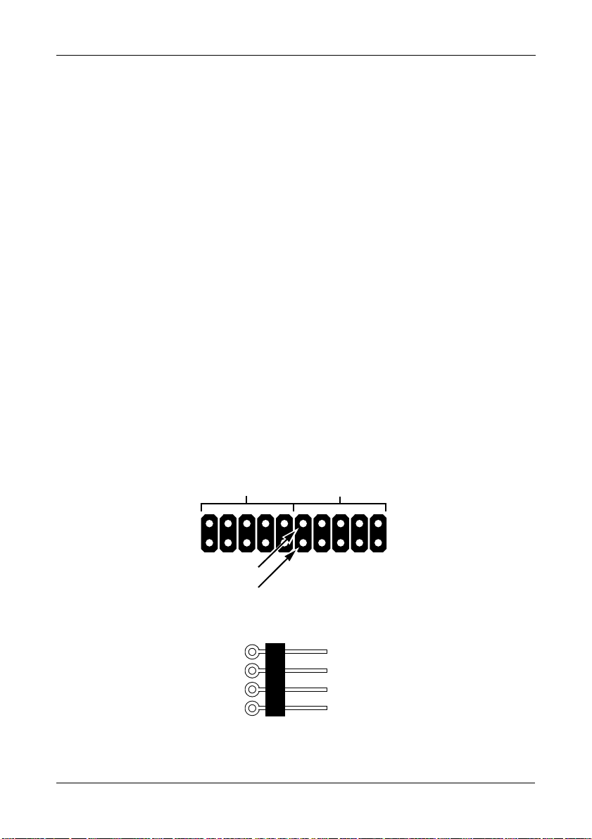
6. Optional. To connect your LEDs, follow one of the following diagrams:
• Individual LEDs.
Fault LEDs – CN7
(planned feature)
–
+
Ground
Unused
• Aggregated or Global Activity LEDs.
Activity LEDs – CN8
Port/Channel
11
–
+
1234
+
–
–
+
Page 18
FastTrak TX4650, TX2650 User Manual
Creating Your Logical Drive
You will now use the onboard FastBuild BIOS utility to create a logical drive with
the attached drives.
For an explanation of the logical drive concepts, see Chapter 6
Note
You can omit this step, proceed with the WebPAM installation on
page 16, then create your logical drive using WebPAM. See
“Creating a Logical Drive” on page 80.
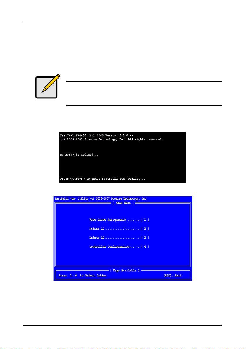
1. Boot your system. If this is the first time you have booted with the FastTrak
card and drives installed, the Promise onboard BIOS will display the
following screen (below).
2. Press the Ctrl-F keys to display the FastBuild Utility Main Menu (below).
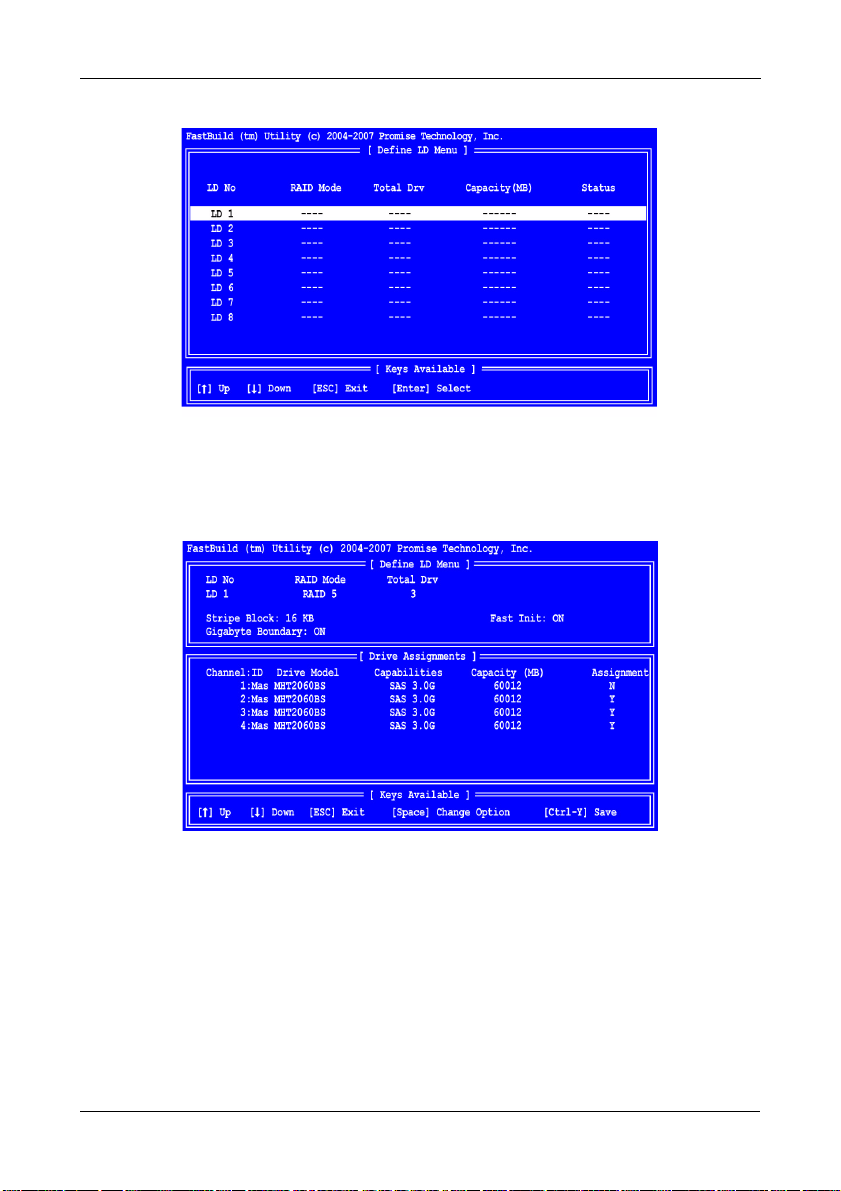
3. Press 2 on the Main Menu screen to display the Define LD Menu (below).
12
Page 19
Chapter 2: Installation
4. Press the arrow keys to highlight an logical drive number you want to define
and press Enter to select it.
The Define LD Menu for the logical drive number you selected will next
appear (below).
5. Choose the RAID Level you want. In the Define LD Menu section, press the
Spacebar to toggle through logical drive types:
•RAID 0 (Stripe)
• RAID 1 (Mirror)
• RAID 5 (Distributed Parity)
• RAID 10 (Stripe/Mirror)
• JBOD (Single Drive)
See “Introduction to RAID” on page 109 for more information.
13
Page 20

FastTrak TX4650, TX2650 User Manual
6. Press the arrow keys to move to the next option. Option choices depend on
the RAID Level you selected.
• Fast Init erases the Master Boot Record (MBR) of the physical drives
when this feature is set to ON. ON is recommended.
• Gigabyte Boundary enables replacement of a failed physical drive with a
slightly smaller physical drive when this feature is set to ON. ON is
recommended.
• Stripe Block Size. Set to 16 KB with no options. Applies to RAID but not
to JBOD.
7. Press the arrow keys to move to Disk Assignments. Press the spacebar to
toggle between N and Y for each available drive. Y means this physical drive
will be assigned to the logical drive.
Assign the appropriate number of physical drives to your logical drive.
8. Press Ctrl-Y to save your logical drive configuration.
If you set Fast Init to ON, the following message displays:
• Press Ctrl-Y to continue logical drive creation and perform the Fast
Initialization.
• Press any other key to cancel logical drive creation.
The Modify Array Capacity message displays:
9. Press any key to continue.
See “Creating a Logical Drive” on page 40 for information about this option.
10. Press Esc to exit to the Main Menu. Press Esc again to exit the Utility.
11. Press Y to restart your computer.
You have successfully created a new RAID logical drive.
Important
You must be partition and format your new logical drive before you
can use it. Use the same method of partitioning and formatting a
logical drive as you would any other fixed disk added to your
computer system.
14
Page 21
Chapter 2: Installation
Installing WebPAM
Important
Install the FastTrak software driver for your operating system
before installing WebPAM. See “Chapter 3: Installing Drivers” on
page 23 for instructions.
WebPAM installation software will install two major components:
• Utility Server – WebPAM RAID monitoring and Networking software
• Java Runtime Environment (if not previously installed)
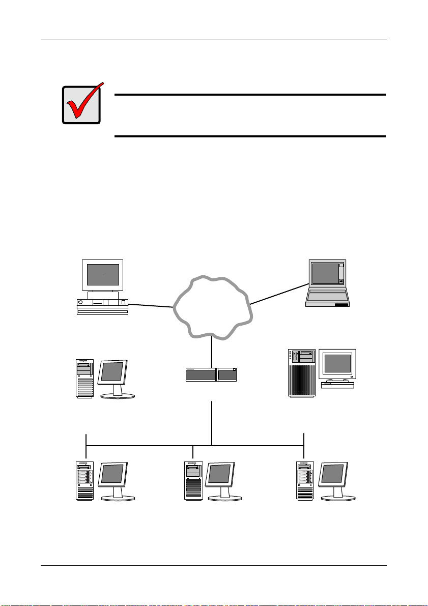
Utility Server
The Utility Server installs on the PC with the FastTrak RAID Controller card (the
“Host PC”).
Figure 3. WebPAM on a network
The
Internet
Desktop PC
with Internet
browser
Laptop PC
with Internet
browser
Networked PC
with Internet browser
Host PC with
FastTrak Controller
Router & Firewall
Host PC with
FastTrak Controller
15
File Server with
Utility Server
Host PC with
FastTrak Controller
Page 22

FastTrak TX4650, TX2650 User Manual
Java Runtime Environment
WebPAM uses a private installation of the Java Runtime Environment (JRE). The
JRE is installed the in WebPAM folder and is only used with WebPAM. Any
existing installation of a JRE or JDK on your PC will not be affected.
Operating System Support
On the Host PC where you install the FastTrak controller and WebPAM, Promise
Technology recommends:
• Windows Vista Business,
Enterprise, or Ultimate
• Windows Server 2003
• Windows XP Professional
WebPAM supports these operating systems. Choose one of them to take full
advantage of all the features of WebPAM.
• Windows 2000
• Red Hat Enterprise 5
• SuSE Linux Enterprise Server 10
Browser Support
On the Host PC where you install the FastTrak card and WebPAM, you must
have one of the following browsers:
• Internet Explorer
• Mozilla
•Firefox
• Netscape Navigator
If you do not have one of the above browsers, install the browser first and make it
the default browser. Then install WebPAM.
Installation
Windows
Follow these steps to install WebPAM on your Windows-based PC or Server.
1. Boot up the PC/server and launch Windows.
If the computer is already running, exit all programs.
2. Insert the software CD into your CD-ROM drive.
3. Double-click the Install CD's icon to open it.
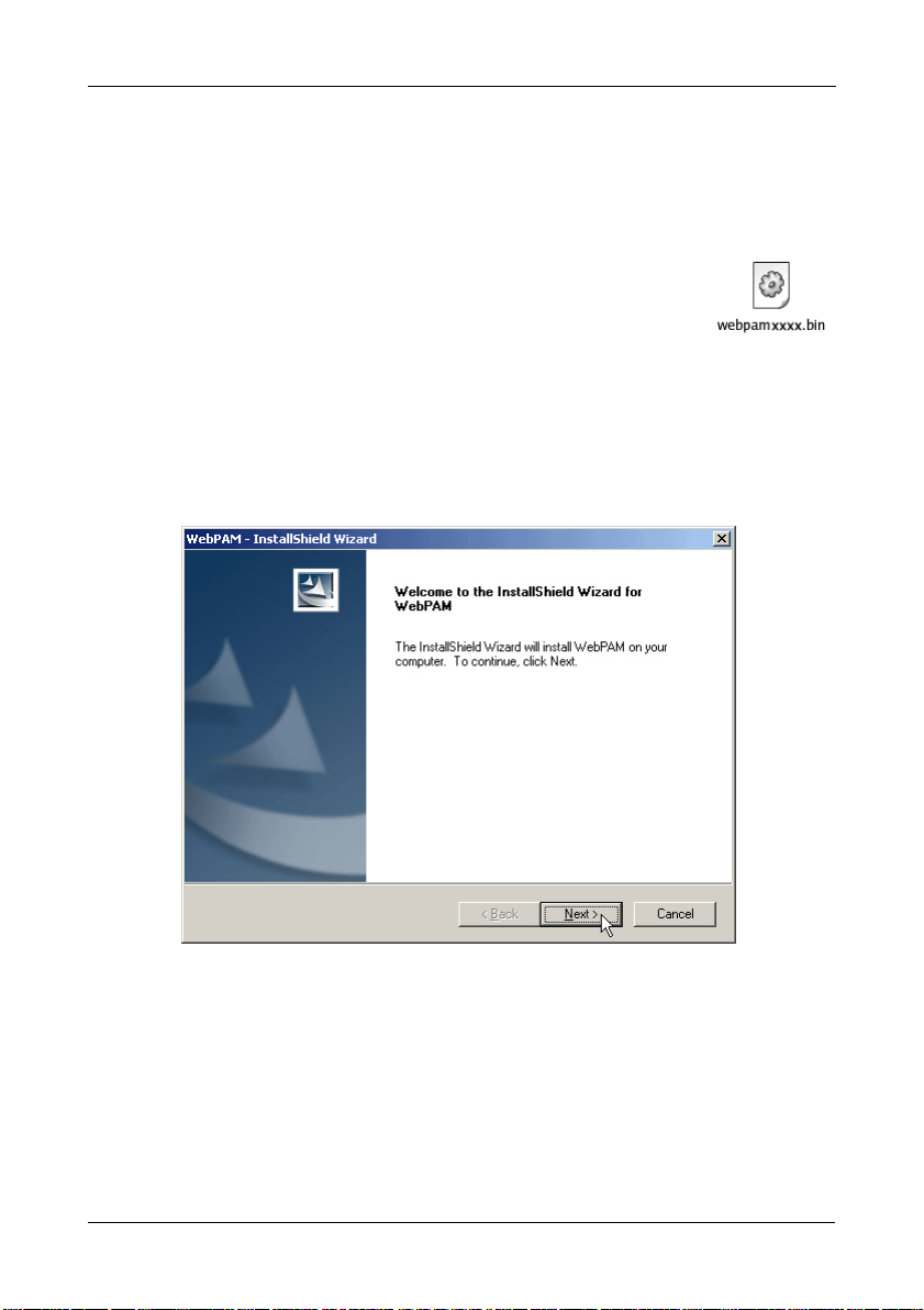
4. Double-click the Installer icon to launch it (right).
The first WebPAM installation dialog box appears. Go to
“WebPAM Installation for Windows and Linux” on page 17
16
Page 23
Chapter 2: Installation
Linux
Follow these steps to install WebPAM on your Linux-based PC or Server.
1. Boot up the PC/server and launch the Linux GUI.
If the computer is already running, exit all programs.
2. Insert the software CD into your CD-ROM drive.
3. In the CD window, double-click the webpam...bin icon to
begin installation (right).
4. When the Run or Display? dialog box appears, click Run in
Terminal.
After several moments, the Terminal window closes and the first WebPAM
installation dialog box appears.
WebPAM Installation for Windows and Linux
The first WebPAM installation dialog box appears, as shown below.
5. When the Introduction screen appears (above), click the Next button.
17
Page 24
FastTrak TX4650, TX2650 User Manual
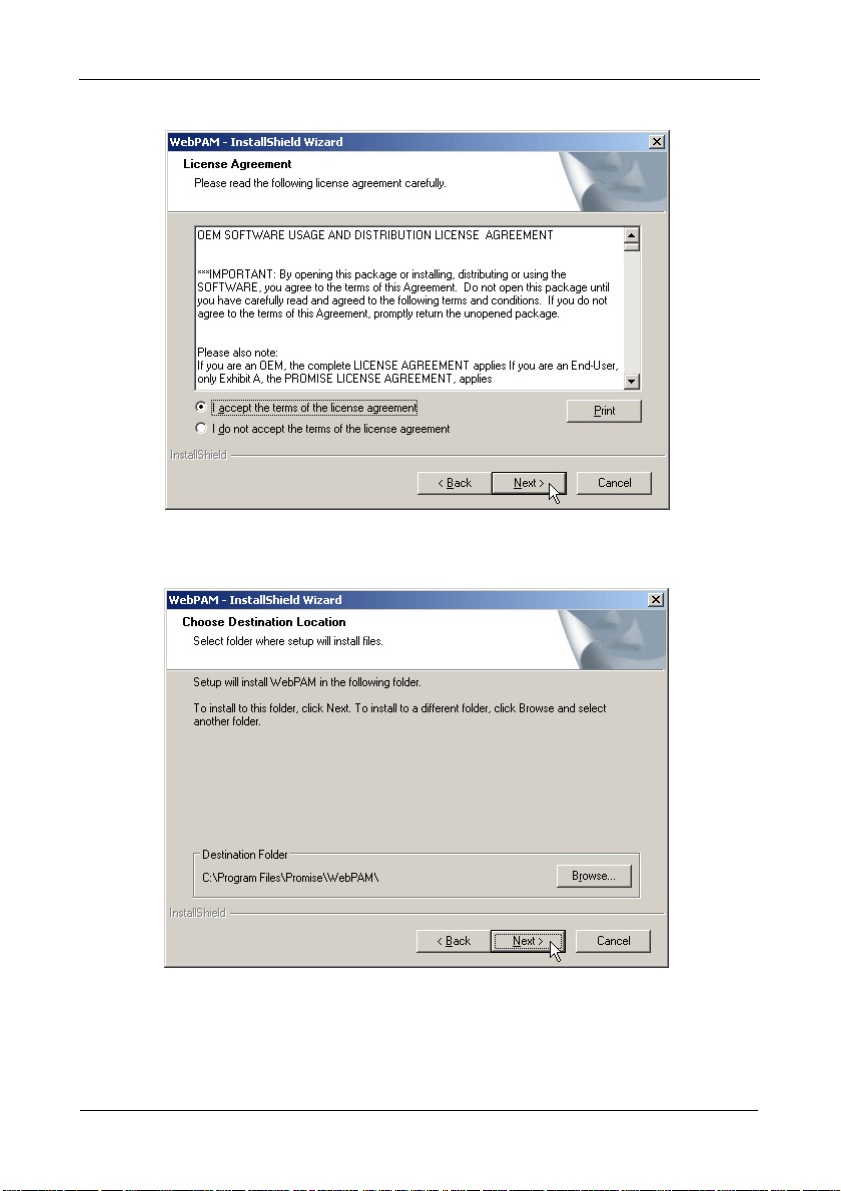
6. When the License Agreement appears (above), click the “I accept the terms
of the license agreement” option. Then click the Next button.
7. When the Choose Install Folder screen appears (above), make your
selection of a folder for the WebPAM applications you are installing. The
default folder is C:\Program Files\Promise\WebPAM\. If you want a
different folder, type its location or click the Browse button and select a new
location.
18
Page 25
Chapter 2: Installation
If you change your mind and want the default location, click the Back button,
then the Next button.
Click the Next button when you are finished.
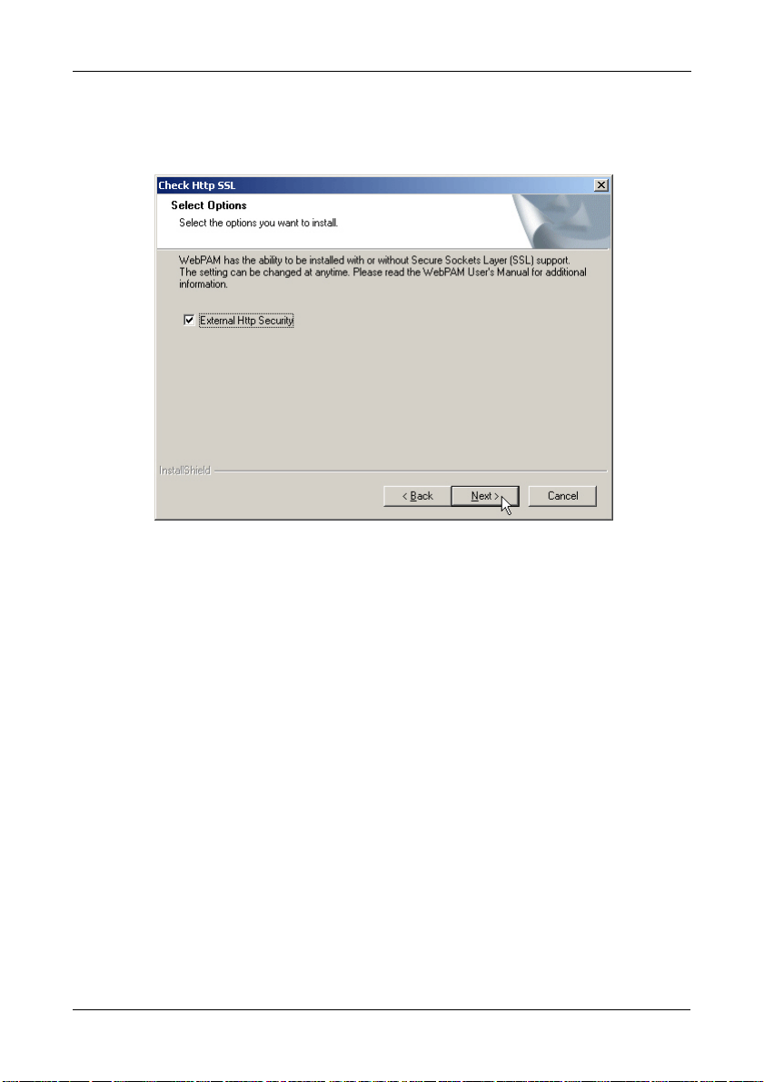
8. When the SSL Security Options screen appears (above), you can check
External Security. An explanation follows.
External SSL Security – Applies security to all connections involving the
Internet or outside your company firewall.
Security options are invisible to authorized users.
Promise Technology provides a default certificate for the server as well as
for internal data communication. However, in some cases, it is better to
install and verify your own certificate for the webserver. And, if possible,
have your certificate verified by a certificate authority such as Verisign or
Thwate. See your MIS Administrator for guidance.
Click the Next button when you have made your choice.
19
Page 26
FastTrak TX4650, TX2650 User Manual
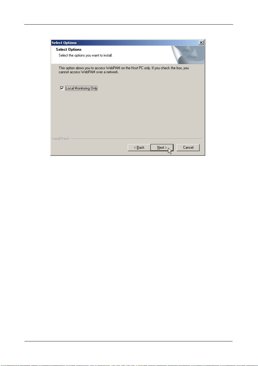
9. When the Select Options screen appears (above), you have the option of
choosing Local Monitoring Only.
• If you check this option, you can only log into WebPAM from the Host
PC. You cannot log into WebPAM over a network.
• If you do not check this option, you can log into WebPAM from the Host
PC or over a network.
To continue, click the Next button.
20
Page 27
Chapter 2: Installation
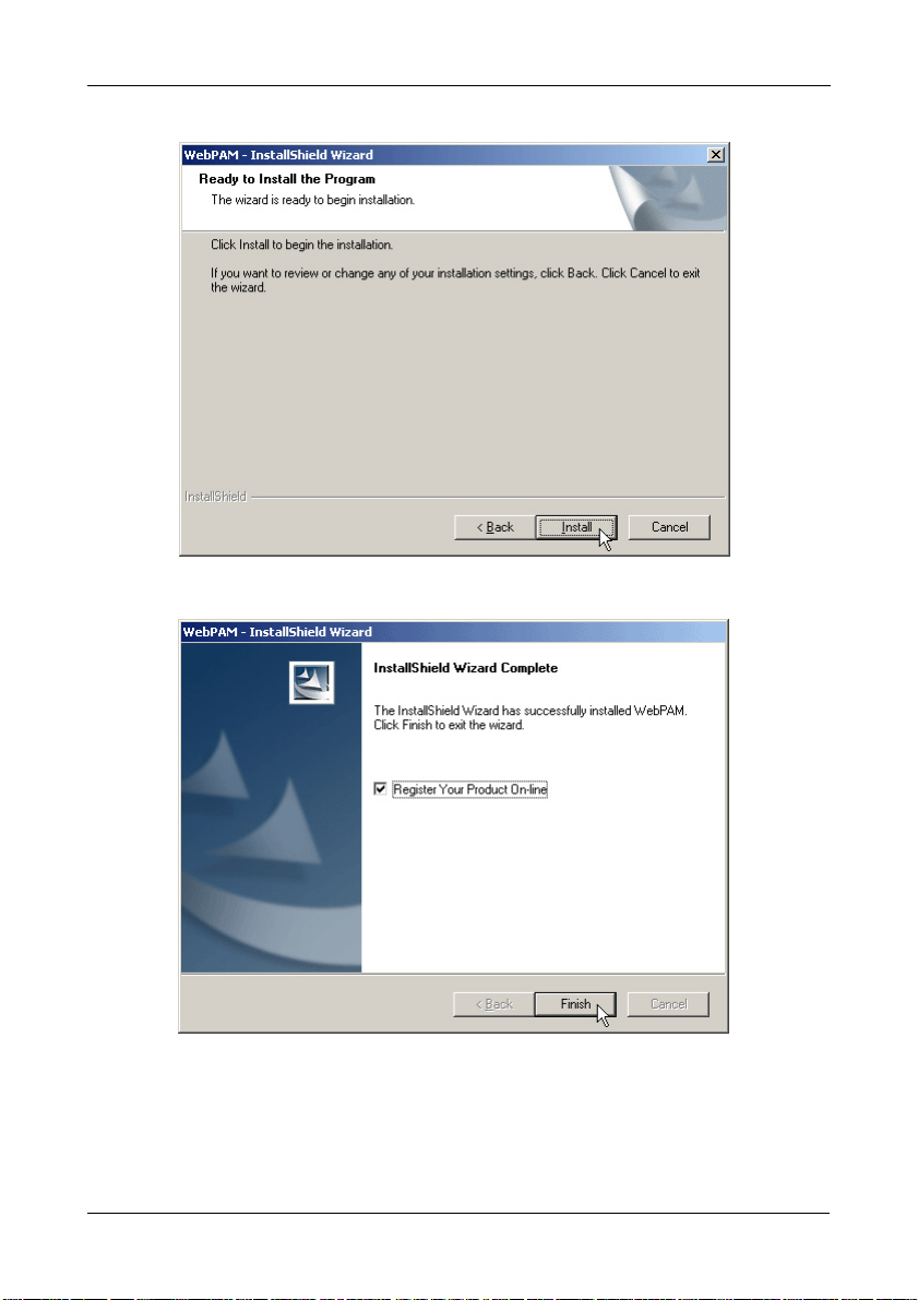
10. When the Ready to Install screen appears (above), click the Install button.
11. When the Install Complete screen appears (above), the installation process
is finished. Click the Finish button to go to the Promise Registration website.
21
Page 28

FastTrak TX4650, TX2650 User Manual
Important
Registration of your FastTrak and WebPAM provides useful
information that helps Promise Technologies to offer better
products and support. Please take a few minutes to register.
Thanks!
This completes the WebPAM installation. Go to “Chapter 5: WebPAM” on
page 53 for information about using WebPAM.
22
Page 29

Chapter 3: Installing Drivers
• FastTrak Driver Diskette for Windows (page 24)
• USB Memory Stick for Windows (page 24)
• FastTrak Driver Diskette for Linux (page 25)
•Windows Vista
• New OS Installation (page 26)
• Existing System (page 27)
• Confirming Driver Installation (page 27)
• Windows Server 2003
• New OS Installation (page 28)
• Existing System (page 29)
• Confirming Driver Installation (page 29)
•Windows XP
• New OS Installation (page 30)
• Existing System (page 31)
• Confirming Driver Installation (page 31)
• Windows 2000
• New OS Installation (page 32)
• Existing System (page 33)
• Confirming Driver Installation (page 33)
• Red Hat Linux Enterprise 5.0
• New OS Installation (page 34)
• Existing System (page 34)
• SuSE Linux Enterprise Server 10.0
• New OS Installation (page 35)
• Existing System (page 35)
Following are driver installation procedures for the Windows operating systems
that support the FastTrak TX Series SATA /SAS RAID Controller card. The
FastTrak drivers for Windows and Linux are included on the CD.
Please download the latest drivers from the Promise website at
http://www.promise.com/support.
23
Page 30

FastTrak TX4650, TX2650 User Manual
FastTrak Driver Diskette for Windows
If you have a Windows PC and plan to install your FastTrak driver from a
diskette, follow this procedure. This procedure requires one write-enabled blank
3.5-inch diskette.
1. Place your blank diskette in the appropriate drive.
2. Insert the Promise CD into your CD-ROM drive.
The display screen should open automatically.
If the display screen does not open, click MyComputer > CD Drive D: and
double-click the Launch.exe icon.
3. Click the Windows Driver button.
The Disk Copy Utility opens.
4. Click the Create button in the Utility.
A confirmation box appears.
5. Click the Yes button in the confirmation box.
The utility prepares your driver diskette.
When the utility is finished, it displays a message.
6. In the message, click the OK button, then click the Exit button to close the
Promise CD.
USB Memory Stick for Windows
If you have a Windows PC and plan to install your FastTrak driver from a USB
memory stick, follow this procedure. This procedure requires one write-enabled
USB memory stick.
1. Attach your USB memory stick to the USB port.
2. Insert the Promise CD into your CD-ROM drive.
3. Click MyComputer > CD Drive D: go to the Windows Driver folder.
4. Manually copy the driver files to you USB memory stick.
24
Page 31

Chapter 3: Installing Drivers
FastTrak Driver Diskette for Linux
If you have a Linux PC and plan to install your FastTrak driver from a diskette,
follow this procedure. This procedure requires one write-enabled blank 3.5-inch
diskette.
1. Place your blank diskette in the appropriate drive.
2. Insert the Promise CD into your CD-ROM drive.
The display screen should open automatically.
If the display screen does not open, open the CD manually in your graphic
user interface.
3. Click the Linux Driver button.
4. Manually copy the driver image file to your PC’s hard drive or a USB memory
stick.
5. Do one of the following actions:
• On a Windows PC – Type rawrite.exe to extract the driver image file to
the blank diskette.
• On a Linux PC – Type dd if=<imageFileName>
of=<floppyDeviceName> bs=10k to extract the driver image file to the
blank diskette.
Where <imageFileName> is the driver image file name and
<floppyDeviceName> is the device name, such as /dev/ fd0.
25
Page 32

FastTrak TX4650, TX2650 User Manual
Windows Vista
New OS Installation
The following details the installation of the FastTrak TX Series RAID Controller
drivers while installing Windows Vista.
1. Start the installation: Boot from the DVD-ROM.
2. When the “Where do you want to install Windows?” dialog box appears, click
Load Driver.
3. Insert the FastTrak driver diskette into drive A: or attach a USB memory stick
with the FastTrak driver to the USB port.
4. In the Load Driver dialog box, click the Browse button.
5. In the Browse for Folder dialog box, click the diskette or USB stick, then click
the OK button.
6. In the “Select the driver to be installed” dialog box, highlight Promise
FastTrak TX [4650, 2650] (tm) Controller, then click the Next button.
7. When the “Where do you want to install Windows?” dialog box appears
again, in the list of Disks, highlight the Disk representing your logical drive
(the Disk with unallocated space), then click the Next button.
8. Continue the Windows installation.
26
Page 33

Chapter 3: Installing Drivers
Existing System
After installing the FastTrak TX Series RAID Controller card and rebooting your
system, Windows Vista setup will show a “Found New Hardware” dialog box.
Under Windows Vista, “RAID Controller” will be displayed.
1. Insert the FastTrak driver diskette into drive A: or attach a USB memory stick
with the FastTrak driver to the USB port.
2. Choose Install the software automatically and press the Enter key.
3. Choose Promise FastTrak TX [4650, 2650] (tm) Controller from the list that
appears on screen, and then press the Enter key.
4. If using a driver that has not been digitally signed by Microsoft, you will be
asked if you want to continue the installation. Click Continue anyway.
5. When the New Hardware Wizard has finished installing the FastTrak driver,
click Finish.
Confirming Driver Installation
1. Right-click the My Computer icon and choose Manage from the popup
menu.
2. From the left panel, choose Device Manager.
3. Click the + in front of Storage controllers. “Promise FastTrak TX [4650, 2650]
(tm) Controller” and “Promise Raid Console” should appear.
27
Page 34

FastTrak TX4650, TX2650 User Manual
Windows Server 2003
New OS Installation
The following details the installation of the FastTrak TX Series RAID Controller
drivers while installing Windows Server 2003.
1. Start the installation:
• Floppy Install: Boot the computer with the Windows Server 2003
installation diskettes.
• CD-ROM Install: Boot from the CD-ROM. Press F6 after the message
“Press F6 if you need to install third party SCSI or RAID driver” appears.
2. When the Windows Server 2003 Setup window is generated, press S to
specify an Additional Device(s).
3. Insert the FastTrak driver diskette into drive A: and press Enter.
4. Choose Promise FastTrak TX [4650, 2650] (tm) Controller from the list that
appears on screen, and then press the Enter.
5. Press S to use the driver on the floppy disk and then press Enter to continue
with installation.
6. The Windows Server 2003 Setup screen will appear again saying “Setup will
load support for the following mass storage devices:” The list will include
“Promise FastTrak TX [4650, 2650] (tm) Controller”.
NOTE: If there are any additional devices to be installed, specify them now.
When all devices are specified, continue to the next step.
7. From the Windows Server 2003 Setup screen, press the Enter. Setup will
now load all device files and then continue the Windows Server 2003
installation.
28
Page 35

Chapter 3: Installing Drivers
Existing System
After installing the FastTrak TX Series RAID Controller card and rebooting your
system, Windows Server 2003 setup will show a “Found New Hardware” dialog
box. Under Windows 2003, “RAID Controller” will be displayed.
1. Insert the FastTrak driver diskette into the A:\ drive.
2. Choose Install the software automatically and press the Enter key.
3. Choose Promise FastTrak TX [4650, 2650] (tm) Controller from the list that
appears on screen, and then press the Enter key.
4. If using a driver that has not been digitally signed by Microsoft, you will be
asked if you want to continue the installation. Click Continue anyway.
5. When the New Hardware Wizard has finished installing the FastTrak driver,
click Finish.
Confirming Driver Installation
1. Right-click the My Computer icon and choose Manage from the popup
menu.
2. From the left panel, choose Device Manager.
3. Click the + in front of SCSI and RAID controllers. “Promise FastTrak TX
[4650, 2650] (tm) Controller” and “Promise Raid Console” should appear.
29
Page 36

FastTrak TX4650, TX2650 User Manual
Windows XP
New OS Installation
The following details the installation of the FastTrak TX Series RAID Controller
drivers while installing Windows XP.
1. Start the installation:
• Floppy Install: Boot the computer with the Windows XP installation
diskettes.
• CD-ROM Install: Boot from the CD-ROM. Press F6 after the message
“Press F6 if you need to install third party SCSI or RAID driver” appears.
2. When the Windows XP Setup window is generated, press S to specify an
Additional Device(s).
3. Insert the FastTrak driver diskette into drive A: and press Enter.
4. Choose Promise FastTrak TX [4650, 2650] (tm) Controller from the list that
appears on screen, and then press the Enter.
5. Press S to use the driver on the floppy disk and then press Enter to continue
with installation.
6. The Windows XP Setup screen will appear again saying “Setup will load
support for the following mass storage devices:” The list will include
“Promise FastTrak TX [4650, 2650] (tm) Controller”.
NOTE: If there are any additional devices to be installed, specify them now.
When all devices are specified, continue to the next step.
7. From the Windows XP Setup screen, press the Enter. Setup will now load all
device files and then continue the Windows XP installation.
30
Page 37

Chapter 3: Installing Drivers
Existing System
After installing the FastTrak TX Series RAID Controller card and rebooting your
system, Windows XP setup will show a “Found New Hardware” dialog box.
1. Insert the FastTrak driver diskette into the A:\ drive.
2. Choose Install the software automatically and press the Enter key.
3. Choose Promise FastTrak TX [4650, 2650] (tm) Controller from the list that
appears on screen, and then press the Enter key.
4. If using a driver that has not been digitally signed by Microsoft, you will be
asked if you want to continue the installation. Click Continue anyway.
5. When the New Hardware Wizard has finished installing the FastTrak driver,
click Finish.
Confirming Driver Installation
1. Right-click the My Computer icon and choose Manage from the popup
menu.
2. From the left panel, choose Device Manager.
3. Click the + in front of SCSI and RAID controllers. “Promise FastTrak TX
[4650, 2650] (tm) Controller” and “Promise Raid Console” should appear.
31
Page 38

FastTrak TX4650, TX2650 User Manual
Windows 2000
New OS Installation
The following details the installation of the FastTrak TX Series RAID Controller
drivers while installing Windows 2000.
1. Start the installation:
• Floppy Install: Boot the computer with the Windows 2000 installation
diskettes.
• CD-ROM Install: Boot from the CD-ROM. Press F6 after the message
“Press F6 if you need to install third party SCSI or RAID driver” appears.
2. When the Windows 2000 Setup window is generated, press S to specify an
Additional Device(s).
3. Insert the FastTrak driver diskette into drive A: and press Enter.
4. Choose Promise FastTrak TX [4650, 2650] (tm) Controller from the list that
appears on screen then press Enter.
5. The Windows 2000 Setup screen will appear again saying “Setup will load
support for the following mass storage devices:” The list will include
“Promise FastTrak TX [4650, 2650] (tm) Controller”.
NOTE: If there are any additional devices to be installed, specify them now.
When all devices are specified, continue to the next step.
6. From the Windows 2000 Setup screen, press Enter. Setup will now load all
device files and then continue the Windows 2000 installation.
32
Page 39

Chapter 3: Installing Drivers
Existing System
After installing the FastTrak TX Series RAID Controller card and rebooting your
system, Windows 2000 setup will show a “New Hardware Found” dialog box.
Under Windows 2000, “PCI Mass Storage Controller” will be displayed.
1. Choose Add New Hardware Wizard from the list, and then press Enter.
2. Choose Add/Troubleshoot a device and click Next. The new hardware
wizard will show device list
3. Choose Mass Storage controller and click Next. At the following screen click
Finish.
4. Choose Display a list the known drivers for this device so that I can choose a
specific driver then click Next.
5. When the Windows 2000 supported SCSI adapter drivers list appears, click
Have disk.
6. Insert the FastTrak driver diskette in drive A:\.
7. Type A:\Win2000 in the text box. Click OK.
8. Choose Promise FastTrak TX [4650, 2650] (tm) Controller from the list that
appears on screen, then click Next.
9. Click Yes to confirm continue the installation and copy the driver to system.
10. Remove the diskette and click Finish to restart the system.
Windows 2000 will then restart for the driver installation to take effect.
Confirming Driver Installation
1. Right-click the My Computer icon and choose Manage from the popup
menu.
2. From the left panel, choose Device Manager.
3. Click the + in front of SCSI controllers. “Promise FastTrak TX [4650, 2650]
(tm) Controller” and “Promise Raid Console” should appear.
33
Page 40

FastTrak TX4650, TX2650 User Manual
Red Hat Linux Enterprise 5.0
New OS Installation
1. Start the RedHat Linux Installation by booting from the install CD.
At the “Welcome to Red Hat Linux...” installation screen, a prompt labeled
boot: will appear at the bottom of the screen.
2. Type linux dd acpi=off and press Enter.
3. When the Installer asks, “Do you have a driver disk?” click Yes .
4. At the “Insert your driver disk and press OK to continue,” insert the driver
diskette into the floppy drive and click OK.
5. Continue with the installation normally.
Note
On first installation mode, do not choose the Virtualization option.
FastTrak does not support it.
Existing System
1. Insert FastTrak driver diskette into the floppy drive.
2. Log in as root.
3. Type mount -r /dev/fd0 /media/floppy.
4. Type cd /media/floppy
5. Type sh ./install.
6. When the installer asks, “You are installing a driver on an existing OS. Is it
true (y/n)?” type Y and press Enter.
7. Type cd; umount /media/floppy.
8. Remove the FastTrak driver diskette.
9. Type reboot to restart the system.
34
Page 41

Chapter 3: Installing Drivers
SuSE Linux Enterprise Server 10.0
New OS Installation
1. Start the SuSE Linux Installation by booting from the install CD.
2. As the system boots, press F5 for the Driver Disk.
3. Move the cursor to the Installation – ACPI Disabled option, and press Enter.
4. When the installer displays, “Please insert the Driver Update floppy/
CDROM,” insert the FastTrak driver disk, then press Enter.
5. When the Driver Update Menu pops up, click OK, then click Back to return
to the installer.
6. Follow the on-screen prompts to complete the installation.
Existing System
1. Insert the FastTrak driver diskette into the floppy drive.
2. Log in as root.
3. Type mount /dev/fd0 /media/floppy.
4. Type cd /media/floppy
5. Type ./install.
6. Type cd; umount /media/floppy.
7. Remove the FastTrak driver diskette.
8. Type reboot to restart the system.
35
Page 42

FastTrak TX4650, TX2650 User Manual
36
Page 43

Chapter 4: FastBuild™ Utility
• Using the FastTrak BIOS (below)
• Navigating the Main Menu
(page 38)
• Viewing Drive Assignments
(page 39)
• Creating a Logical Drive (page 40)
• Creating Two Logical Drives
(page 43)
• Deleting a Logical Drive (page 49)
• Viewing the Controller
Configuration (page 51)
• Responding to Logical Drive
Problems (page 52)
Using the FastTrak BIOS
The FastTrak BIOS is a built-in component of the FastTrak TX Series SAS/SATA
RAID Controller card.
When the FastTrak BIOS loads during bootup, it displays pertinent information
about the RAID logical drives that it finds. At this point, you can press Ctrl-F to
enter the FastBuild Utility.
When the FastTrak BIOS screen appears, press Ctrl-F to enter the FastBuild
Utility.
The FastTrak BIOS screen displays the following information:
ID – An identification number assigned to each logical drive by the BIOS.
Mode – The RAID mode (level) configuration of the logical drive
Size – The data capacity of the logical drive in MB (Megabytes).
Track-Mapping – This is the CHS (Cylinder/Head/Sector) equivalent of the
logical drive geometry as hosted by the FastTrak BIOS int 13h disk services.
Status – Shows one of three logical drive conditions:
37
Page 44

FastTrak TX4650, TX2650 User Manual
Functional – The logical drive is fully operational, and no problems are
present.
Critical – The logical drive is operational, but has lost its fault tolerance. For
RAID 1, 5, or 10, the logical drive contains a failed drive. You must identify
and replace the failed physical (disk) drive.
Offline – The logical drive is no longer operational and the FastBuild utility
cannot rebuild it. You must identify and replace the failed drive(s). Then you
can create a new logical drive and copy your data to it from the last tape
backup or other device.
• For RAID 1, 5, or 10, two or more physical drives in the logical drive
have failed.
• For a RAID 0 or JBOD, one physical drive has failed.
Navigating the Main Menu
When the FastTrak BIOS displays on your computer screen, press Ctrl-F to
launch the FastBuild utility and display the Main Menu.
The Main Menu (above) has five options:
• Press 1 to view physical drive assignments
• Press 2 to create a logical drive or view information about an existing logical
drive.
• Press 3 to delete a logical drive.
• Press 4 to view and change controller configuration.
• Press Esc (Escape) to exit the menu.
38
Page 45

Chapter 4: FastBuild™ Utility
Viewing Drive Assignments
From the Main Menu screen, press 1 to see the View Drive Assignments screen.
The View Drive Assignments screen reports physical (disk) drive assignments
and provides the following information:
Channel: ID – Shows the FastTrak Controller channel (port) ID number to which
each physical drive is attached.
Drive Model – Identifies the manufacturer, model, and model number (if
applicable) of each physical drive.
Capabilities – Refers to the type of physical drive, SAS or SATA, and the drive’s
data rate in Gb/s.
Capacity (MB) – Reflects the capacity in MB (megabytes) of the physical drive.
The effective capacity of the physical drive is slightly smaller than its maximum
rated capacity.
Assignment – This field identifies the logical drive to which the physical drive
belongs. LD 1-2 means logical drive 1, physical drive 2. JBOD also appears as
LD on this screen.
Unassigned physical drives are labeled Free. Unassigned drives may also be
used to create a new logical drive at any time.
Extent – Refers to the all or part of the physical drive’s capacity allocated to a
logical drive. If you create two logical drives using the same set of physical
drives, each physical drive will display two Extents.
39
Page 46

FastTrak TX4650, TX2650 User Manual
Creating a Logical Drive
The following action will create one logical drive on a set of physical drives. You
can also create two logical drives on the same set of physical drives. See
“Creating Two Logical Drives” on page 43.
To create a logical drive:
1. From the Main Menu screen, press 2 to display the Define LD Menu.
2. Press the arrow keys to highlight an logical drive number you want to define
and press Enter to select it.
The Define LD Menu appears for the logical drive number you selected.
40
Page 47

Chapter 4: FastBuild™ Utility
3. Choose the RAID Level you want. In the Define LD Menu section, press the
Spacebar to toggle through logical drive types:
•RAID 0 (Stripe)
• RAID 1 (Mirror)
• RAID 5 (Distributed Parity)
• RAID 10 (Stripe/Mirror)
• JBOD (Single Drive)
Only the FastTrak TX4650 supports RAID 5 and RAID 10. See “Introduction
to RAID” on page 109 for more information.
4. Press the down arrow key to move to the next option. Option choices
depend on the RAID Level you selected.
• Fast Init erases the Master Boot Record (MBR) of the physical drives
when this feature is set to ON. ON is recommended.
• Gigabyte Boundary enables replacement of a failed physical drive with a
slightly smaller physical drive when this feature is set to ON. ON is
recommended.
• Stripe Block Size. Set to 16 KB with no options. Applies to RAID but not
to JBOD.
5. Press the down arrow key to move to Disk Assignments. Press the spacebar
to toggle between N and Y for each available drive. Y means this physical
drive will be assigned to the logical drive.
41
Page 48

FastTrak TX4650, TX2650 User Manual
Assign the appropriate number of physical drives to your logical drive.
6. Press Ctrl-Y to save your logical drive configuration.
If you set Fast Init to ON, the following message displays:
Press Ctrl-Y again to create the logical drive and perform the Fast
Initialization.
The Modify Array Capacity message displays:
7. Press any key to continue.
The Define LD menu displays your new logical drive.
8. Press Esc to exit to the Main Menu. Press Esc again to exit the Utility.
9. Press Y to restart your computer.
You have successfully created a new RAID logical drive.
You must be partition and format your new logical drive before you can use
it. See “Appendix A: Partition and Format” on page 137.
42
Page 49

Chapter 4: FastBuild™ Utility
Creating Two Logical Drives
The following action will create two logical drive on the same set of physical
drives. You can also create one logical drive on a set of physical drives. See
“Creating a Logical Drive” on page 40
To create a logical drive:
1. From the Main Menu screen, press 2 to display the Define LD Menu.
2. Press the arrow keys to highlight LD 1 and press Enter to select it.
The Define LD Menu for LD 1 appears.
43
Page 50

FastTrak TX4650, TX2650 User Manual
3. Choose the RAID Level you want. In the Define LD Menu section, press the
Spacebar to toggle through logical drive types:
•RAID 0 (Stripe)
• RAID 1 (Mirror)
• RAID 5 (Distributed Parity)
• RAID 10 (Stripe/Mirror)
You can create your two logical drives with different RAID levels. But you
cannot combine a logical drive and JBOD.
Only the FastTrak TX4650 supports RAID 5 and RAID 10. See “Introduction
to RAID” on page 109 for more information.
4. Press the down arrow key to move to the next option. Option choices
depend on the RAID Level you selected.
• Fast Init erases the Master Boot Record (MBR) of the physical drives
when this feature is set to ON. ON is recommended.
• Gigabyte Boundary enables replacement of a failed physical drive with a
slightly smaller physical drive when this feature is set to ON. ON is
recommended.
• Stripe Block Size. Set to 16 KB with no options.
5. Press the down arrow key to move to Disk Assignments. Press the spacebar
to toggle between N and Y for each available drive. Y means this physical
drive will be assigned to the logical drive.
44
Page 51

Chapter 4: FastBuild™ Utility
Assign the appropriate number of physical drives to your logical drive.
6. Press Ctrl-Y to save your logical drive configuration.
If you set Fast Init to ON, the following message displays:
Press Ctrl-Y again to create the logical drive and perform the Fast
Initialization.
The Modify Array Capacity message displays:
7. Press Ctrl-Y to continue.
The Define LD Menu displays the maximum available capacity of the
physical drives and prompts you to enter the capacity for the first logical
drive.
8. Type the capacity for the first logical drive, then press Enter.
The Define LD Menu displays the first logical drive.
45
Page 52

FastTrak TX4650, TX2650 User Manual
9. Press the arrow keys to highlight a logical drive number you want to define
and press Enter to select it.
The Define LD Menu appears for the logical drive number you selected. Note
the reduced capacity of the physical drives used for the first logical drive.
10. Choose the RAID Level you want. In the Define LD Menu section, press the
Spacebar to toggle through logical drive types:
46
Page 53

Chapter 4: FastBuild™ Utility
•RAID 0 (Stripe)
• RAID 1 (Mirror)
• RAID 5 (Distributed Parity)
• RAID 10 (Stripe/Mirror)
You can create your two logical drives with different RAID levels. But you
cannot combine a logical drive and JBOD.
Only the FastTrak TX4650 supports RAID 5 and RAID 10. See “Introduction
to RAID” on page 109 for more information.
11. Press the down arrow key to move to the next option. Option choices
depend on the RAID Level you selected.
• Fast Init erases the Master Boot Record (MBR) of the physical drives
when this feature is set to ON. ON is recommended.
• Gigabyte Boundary enables replacement of a failed physical drive with a
slightly smaller physical drive when this feature is set to ON. ON is
recommended.
• Stripe Block Size. Set to 16 KB with no options.
12. Press the down arrow key to move to Disk Assignments. Press the spacebar
to toggle between N and Y for each available drive. Y means this physical
drive will be assigned to the logical drive.
Assign the appropriate number of physical drives to your logical drive.
13. Press Ctrl-Y to save your logical drive configuration.
If you set Fast Init to ON, the following message displays:
Press Ctrl-Y again to create the logical drive and perform the Fast
Initialization.
The Define LD menu displays your new logical drive
47
Page 54

FastTrak TX4650, TX2650 User Manual
.
14. Press Esc to exit to the Main Menu. Press Esc again to exit the Utility.
15. Press Y to restart your computer.
You have successfully created a new RAID logical drives.
You must be partition and format your new logical drive before you can use
it. See “Appendix A: Partition and Format” on page 137.
48
Page 55

Chapter 4: FastBuild™ Utility
Deleting a Logical Drive
Caution
Deletion of an existing logical drive will result in the loss of all data
saved on the logical drive.
Record all logical drive information, including RAID level, disk
members, stripe block size and gigabyte boundary, in case you
wish to undo a deletion.
Logical drives may possibly be recovered after deletion by
immediately re-defining the logical drive with information identical
to the original configuration.
To delete a logical drive:
1. From the Main Menu screen, press 3 to display the Delete LD Menu.
2. Highlight the logical drive you want to delete and press the Del key or Alt-D.
The View LD Definition Menu for the selected logical drive appears.
49
Page 56

FastTrak TX4650, TX2650 User Manual
3. Press Ctrl-Y to confirm deletion of the logical drive.
The screen returns to the Delete LD Menu. The deleted logical drive no
longer appears in the Menu.
Press Esc to return to the Main Menu.
50
Page 57

Chapter 4: FastBuild™ Utility
Viewing the Controller Configuration
From the Main Menu screen, press 4 to display the Controller Configuration
Options screen (below).
The information in the System Resources section might be helpful for
troubleshooting purposes:
• The system IRQ used by the FastTrak card
• ATA IO Base Address
• Host IO Base Address
• Function MMIO Base Address
• Flash ROM Base Address
• AHCI HBA MMIO Base Address
Press Esc to return to the Main Menu.
51
Page 58

FastTrak TX4650, TX2650 User Manual
Responding to Logical Drive Problems
When you boot your system, the FastTrak BIOS screen informs you if there is a
critical or offline logical drive. RAID 1, 5, or 10 logical drives go Critical when one
physical drive fails. RAID 0 and JBOD go Offline when a physical drive fails.
Choose one of the following applications to identify the failed drive:
• FastBuild Utility – See “Finding a Failed Drive in FastBuild” below.
• WebPAM – Allow your PC to finish booting, then launch WebPAM.
See “Responding to a Critical or Offline Logical Drive” on page 101 for more
information.
Finding a Failed Drive in FastBuild
1. Press Ctrl-F to enter the FastBuild Utility.
2. In the Main Menu, press 1 to display View Drive Assignments, then look for a
physical drive that was present before but no longer appears.
The failed drive is attached to the missing channel.
In some cases, the FastTrak Controller will begin to rebuild your logical drive
automatically. From the Main Menu, press 2 to display the Define LD Menu
and look under Status.
• If the Status shows Rebuilding, wait for rebuilding to finish, then shut
down your PC and replace the failed drive. The replacement drive will
be Free (unassigned).
• If the Status shows Critical, shut down your PC and replace the failed
drive as soon as possible. The FastTrak Controller will begin rebuilding
your logical drive automatically.
52
Page 59

Chapter 5: WebPAM
• Logging into WebPAM (page 53)
• Logging out of WebPAM (page 55)
• Managing Users (page 56)
• Viewing Host Management
(page 65)
• Making Utility Configuration
Settings (page 66)
• Viewing the FastTrak Card
(page 67)
WebPAM is a RAID management software application. If you have not installed
WebPAM on your PC, see “Installing WebPAM” on page 15.
• Managing the Controller (page 68)
• Managing Physical Drives
(page 73)
• Managing Logical Drives (page 80)
• Managing Enclosures (page 105)
• Managing Spare Drives (page 107)
Logging into WebPAM
Double-click the WebPAM icon on your desktop (right). Or,
1. Launch your Browser.
2. In the Browser address field, type in the IP address of the Host PC, as
explained below.
If you did not choose the External Security option during WebPAM
installation, use the Regular connection. See page 15.
If you chose the External Security option during WebPAM installation, use
the Secure connection.
Regular Connection
• WebPAM uses an HTTP connection . . . . . . . . . . . . . . . . . . . . .http://
• Enter the Host PC’s IP address . . . . . . . . . . . .127.0.0.1 or localhost
• Enter the Port number . . . . . . . . . . . . . . . . . . . . . . . . . . . . . . . :8080
• Add to launch WebPAM. . . . . . . . . . . . . . . . . . . . . . . . . . . . /promise
Together, your entry looks like this:
http://127.0.0.1:8080/promise or https://localhost:8443/promise
Secure Connection
• WebPAM uses a secure HTTP connection . . . . . . . . . . . . . . .https://
• Enter the Host PC’s IP address . . . . . . . . . . . .127.0.0.1 or localhost
• Enter the Port number . . . . . . . . . . . . . . . . . . . . . . . . . . . . . . . :8443
53
Page 60

FastTrak TX4650, TX2650 User Manual
• Add to launch WebPAM. . . . . . . . . . . . . . . . . . . . . . . . . . . . /promise
Together, your entry looks like this:
https://127.0.0.1:8443/promise or https://localhost:8443/promise
Note that the IP address shown above applies to a log-in at the Host PC. When
you log in over a network, you will enter the Host PC’s actual IP address.
Note
If you chose the Local Monitoring Only option during WebPAM
installation, you can only log into WebPAM from the Host PC. You
cannot log into WebPAM over a network.
Figure 3. The WebPAM login screen
When the login screen appears (above):
1. Type admin in the Login ID field.
54
Page 61

Chapter 5: WebPAM
2. Type admin in the Password field.
3. Click the Sign in button.
The Login ID and Password are case sensitive.
Logging out of WebPAM
There are two ways to log out of WebPAM:
• Close your browser window
•Click Logout on the WebPAM banner (below)
After logging out, you must enter your user name and password to log in again.
Clicking Logout brings you back to the Login Screen.
55
Page 62

FastTrak TX4650, TX2650 User Manual
Managing Users
• Adding a User (below)
• Setting Event Notification (page 57)
• Setting a Net Send IP Address
(page 60)
• Deleting a User (page 61)
Adding a User
1. Under Administrative Tools in Tree View, click the User Management
icon.
2. Click the Create tab.
• Changing a User’s Password
(page 61)
• Changing a User’s Email Address
(page 63)
• Changing a User’s Access Rights
(page 63)
3. Type a User ID into the User ID field.
The User ID is the User’s login name.
4. Type the user’s display name into the Display Name field.
The display name could be the User’s actual name.
5. Type a password into the Password field.
Use up to 8 letters and numbers but no spaces or other characters.
6. Type the same password into the Retype Password field.
56
Page 63

Chapter 5: WebPAM
7. If you plan to set up Event Notification, type the user’s email address in the
Email field.
8. Under Host User Rights, check the boxes to select rights for this user.
Right Meaning
Creation Permission to create a logical drive and a spare drive
Deletion Permission to delete a logical drive and a spare drive
Maintenance Permission to migrate, rebuild and synchronize a logical
drive; to run Media Patrol on a physical drive; make
controller and physical drive settings
Notification Permission to receive notification of events affecting the
logical drive
9. Click the Submit button.
Setting Event Notification
1. Under Administrative Tools in Tree View, click the User Management
icon.
2. Click the User ID link.
The user’s information displays.
3. Click the Events tab.
57
Page 64

FastTrak TX4650, TX2650 User Manual
The image above was shortened to fit into the available space.
4. Check the boxes of the notification events that you want to have reported to
you via email and popup messages.
To select events by their severity, check one of the four Select Events boxes
at the top of the window. See the table on the next page.
5. Click the Submit button.
Event Notification Severity Levels
Error Events
Disk Setdown
Disk NON ECC Error
Disk S.M.A.R.T. Error
Array Offline
Synchronization Aborted with Error
Redundancy Check Aborted with Error
Redundancy Check Inconsistency
Found
58
Error Events, continued
Rebuild Aborted with Error
Rebuild Error Aborted Onstream
Background Initialization Aborted with
Error
Migration Aborted with Error
PCI System Error
Memory Multi Bit Error
Unknown (error)
Page 65

Chapter 5: WebPAM
Warning Events
Disk Unplugged
Disk Timeout
Ta s k E r r o r
Disk Media Patrol Aborted with Error
Bad Block Remapped
Disk Pre Fail
Array Critical
Array Degrade
Synchronization Requested
Redundancy Check Rejected
Enclosure Fan Error
Enclosure Voltage 3.3 Out Of Range
Information Events
Disk Plugged In
Disk BSL Update
Disk BSL Cleared
Disk BSL Accessed
Disk Error Fixed
Disk Patrol Progress
Disk Media Patrol Started
Disk Media Patrol Completed
Disk Media Patrol Paused
Disk Media Patrol Resumed
Disk Media Patrol Aborted
Array Online
Array Created
Array Deleted
Array Cache Mode Changed
Array Auto Cache Mode Changed
Synchronization Started
Synchronization Completed
Synchronization Paused
Synchronization Resumed
Synchronization Aborted
Synchronization Progress
Synchronization Inconsistency Fixed
Redundancy Check Started
Redundancy Check Completed
Warning Events, continued
Enclosure Voltage 5 Out Of Range
Enclosure Voltage 12 Out Of Range
Enclosure Temperature Above
Threshold
Battery Temperature Out Of Range
Battery Temperature Unstable
Battery Voltage Out Of Range
Battery Voltage Unstable
Battery Communication Error
BAttery Not Functioning
PCI Parity Error
Single Bit Memory Error
Information Events, continued
Redundancy Check Paused
Redundancy Check Resumed
Redundancy Check Aborted
Redundancy Check Progress
Rebuild Started
Rebuild Completed
Rebuild Paused
Rebuild Resumed
Rebuild Aborted
Rebuild Restarted
Rebuild Progress
Background Initialization Progress
Background Initialization Started
Background Initialization Completed
Background Initialization Paused
Background Initialization Resumed
Background Initialization Aborted
Migration Started
Migration Completed
Migration Paused
Migration Resumed
Migration Aborted
Migration Progress
Battery Becomes Normal
Battery Not Detected
59
Page 66

FastTrak TX4650, TX2650 User Manual
Setting a Net Send IP Address
In WebPAM, each user can set his/her own Net Send IP address or the
Administrator can do it.
Important
Windows Vista and Server 2008 do not support Messenger
Service. To receive messages on those platforms, you must install
a third-party tool.
To set a user’s Net Send IP address:
1. Under Administrative Tools in Tree View, click the User Management
icon.
2. Click the User ID link for the user whose Net Send IP address you want to
set.
3. Click the Settings tab.
60
Page 67

Chapter 5: WebPAM
4. Type a Net Send IP address in the NETSEND IP field.
5. Click the Submit button.
Deleting a User
1. Under Administrative Tools in Tree View, click the User Management
icon.
2. Click the Delete tab.
3. Check the box to the left of the user you want to delete.
4. Click the Delete button.
5. In the Confirmation box, click the OK button.
Changing a User’s Password
In WebPAM, each user can change his/her own password.
To change a user’s password:
1. Log into WebPAM under the User name.
61
Page 68

FastTrak TX4650, TX2650 User Manual
2. Under Administrative Tools in Tree View, click the User Management
icon.
3. Click your User ID link.
4. Click the Settings tab.
5. Type a new password in the New Password field.
6. Retype the new password in the Retype Password field.
7. Click the Submit button.
Important
If a user forgets his/her password, the Administrator must delete
that User and create a new User, as described above.
62
Page 69

Chapter 5: WebPAM
Changing a User’s Email Address
In WebPAM, each user can change his/her own email address or the
Administrator can do it. To change a user’s email address:
1. Under Administrative Tools in Tree View, click the User Management
icon.
2. Click the User ID link for the user whose email address will change.
3. Click the Settings tab.
4. Type a new email address in the Email field.
5. Click the Submit button.
Changing a User’s Access Rights
In WebPAM, the Administrator can change a user’s access rights. To change a
user’s access rights:
63
Page 70

FastTrak TX4650, TX2650 User Manual
1. Log in as the Administrator.
2. Under Administrative Tools in Tree View, click the User Management
icon.
3. Click the User ID link for the user whose access rights will change.
4. Click the Settings tab.
5. Under Host User Rights, check the boxes to assign rights for this user.
Right Meaning
Creation Permission to create a logical drive and a spare drive
Deletion Permission to delete a logical drive and a spare drive
Maintenance Permission to migrate, rebuild and synchronize a logical
drive; to run Media Patrol on a physical drive; make
controller and physical drive settings
Notification Permission to receive notification of events affecting the
logical drive
Uncheck the boxes to remove rights for this user.
6. Click the Submit button.
64
Page 71

Chapter 5: WebPAM
Viewing Host Management
This function provides information only. There are no user settings.
To access Host Management:
1. Under Administrative Tools in Tree View, click the Host Management
icon.
2. Under Host List, click the IP Address link to the host you want to see.
The Host IP address is always 127.0.0.1. If you log in over a network, the
actual IP address of the PC or server with the FastTrak card is shown.
The Information tab displays with information about the Host PC.
• WebPAM Version – The version number of the WebPAM software.
• Display Name – The display name of the Host PC. “localhost” is the default.
• IP Address – 127.0.0.1 is the IP address of the Host PC, accessed at the
Host PC. Other addresses, such as 192.168.1.204, refer to a Host PC
accessed over the network.
• Java Virtual Machine – The version number of the private JVM used by
WebPAM on the Host PC.
65
Page 72

FastTrak TX4650, TX2650 User Manual
Making Utility Configuration Settings
To make utility configuration settings:
1. Under Administrative Tools in Tree View, click the Utility Configuration
icon.
2. Enter the Sender’s address in the Email Sender field.
Be sure the sender has an account in your email system. See your IT
administrator.
3. Enter your email server in the Email Server field.
4. Keep or change the Email Subject line.
5. Type a new interval (in seconds) in the Event Frame Refresh Time field.
30 seconds is the default interval.
6. Click the Submit button when you are done.
66
Page 73

Chapter 5: WebPAM
Viewing the FastTrak Card
The FastTrak–Information tab displays a photograph of the FastTrak TX4650 or
TX2650 card installed in your system.
To display this screen in Management View, click the FastTrak icon in Tree
View.
If you have multiple FastTrak controller cards in the same system, they will
appear under the FastTrak icon as Controller 1, Controller 2, and so on.
67
Page 74

FastTrak TX4650, TX2650 User Manual
Managing the Controller
• Viewing Controller Information (below)
• Making Controller Settings (page 68)
• Viewing Scheduled Actions (page 70)
• Deleting a Scheduled Action (page 70)
• Locking the Controller (page 71)
Viewing Controller Information
The term Controller refers to the device that controls your RAID.
To access the controller, click the Controller icon in Tree View.
The Information tab displays with information about the controller.
• Product Name – The Promise product name for this controller.
• BIOS Version – Version number of the controller’s BIOS.
• Driver Version – Version number of the controller’s software driver.
• Maximum Number of Ports – The number of ports on the controller.
• Maximum Physical Drives – The maximum number of physical (disk)
drives the controller can support.
• Maximum Logical Drives – The maximum number of logical drives (arrays)
the controller can support.
Making Controller Settings
To make controller settings:
1. Click the Controller icon in Tree View.
2. Click the Settings tab in Management View.
68
Page 75

Chapter 5: WebPAM
The controller settings display.
Click the Settings tab to access controller settings.
• Rates – Allocates system resources between the background process (such
as Rebuild, Expansion/Migration, Initialization, and Synchronization) and the
data read/write activity.
A High setting assigns most of the system resources to background
processes. The process will finished sooner but read/write requests are
handled slower.
A Medium setting tries to balance system resources between the
background processes and data input/output activity.
A Low setting assigns most of the system resources to handling read/write
requests. Read/write requests are handled at nearly normal speed while the
background processes take longer.
• Automatic Rebuild Status – When enabled, a critical or degraded logical
drive will rebuild itself automatically after you replace the failed physical
drive. Automatic Rebuilding applies to RAID 1, 5, and 10 logical drives only.
See “Rebuilding a Logical Drive” on page 93 for more information.
• Automatic Rebuild Policy – Directs WebPAM to use either a Free drive or
a Spare drive, or only a Spare drive to rebuild a logical drive. See “Rebuilding
a Logical Drive” on page 93 for more information.
• Buzzer – When enabled, the FastTrak controller’s buzzer will sound to
report a problem.
69
Page 76

FastTrak TX4650, TX2650 User Manual
• S.M.A.R.T. Status – SMART, an acronym for Self-Monitoring Analysis and
Reporting Technology, is a feature of the physical drive software. When
enabled, the FastTrak controller polls the physical drives for SMART
information and reports it to you.
• S.M.A.R.T. Check Polling Interval – The FastTrak controller periodically
polls the physical drives for SMART information and displays it in WebPAM.
Choose an interval from the dropdown menu. The range is 0 to 120 seconds.
A setting of 0 seconds disables the polling function.
Viewing Scheduled Actions
To view scheduled actions:
1. Click the Controller icon in Tree View.
2. Click the Schedule tab.
The Schedule tab lists all scheduled background processes, such as
Rebuild, Media Patrol, Expansion/Migration, Initialization and
Synchronization.
To begin or schedule a Migration, Rebuild, or Synchronization, click the Logical
Drive icon in Tree View then select the appropriate tab in Management View.
To begin or schedule a Media Patrol, click the Physical Drive icon in Tree
View then select the Media Patrol tab in Management View.
Deleting a Scheduled Action
To delete a scheduled action:
1. Click the Controller icon in Tree View.
2. Select the Schedule tab in Management View.
3. Check the box to the left of the process you want to delete.
70
Page 77

Chapter 5: WebPAM
4. Click the Delete button.
5. In the Confirmation box, click the OK button.
Alternative method to delete a scheduled process:
1. Go to its function tab under the Physical Drive icon or Logical Drive
icon.
2. Under Schedule, click the Disable option.
Locking the Controller
The Lock tab displays lock status and enables you to lock or unlock a subsystem
controller. The locking mechanism isolates the controller during maintenance
operations and other periods when you want to avoid interruption from other
users trying to access the logical drives under this controller.
To lock the Controller on the Host PC:
1. Click the Controller icon in Tree View.
2. Select the Lock tab in Management View.
3. From the dropdown menu, select a period of time to hold the lock.
The lock time range is 1 to 30 minutes.
4. Click the Lock button to set the lock.
The lock will release itself automatically at the end of the period you
specified.
71
Page 78

FastTrak TX4650, TX2650 User Manual
To release the lock before the scheduled time, click the Unlock button.
Restoring Default Settings
The Restore tab enables you to restore all of the controller’s settings to their
default values. Use this function for diagnosis and to clear any erroneous user
settings.
To restore the default controller settings:
1. Click the Controller icon in Tree View.
2. Click the Restore tab in Management View.
3. Click the Restore button.
All controller settings are restored to their default values.
72
Page 79

Managing Physical Drives
Chapter 5: WebPAM
• Viewing Physical Drives (below)
• Viewing Physical Drive Information
(page 74)
• Making Physical Drive Settings
(page 75)
• Running Media Patrol (page 75)
• Checking the Bad Sector Log
(page 77)
• Locating a Physical Drive
(page 78)
Viewing Physical Drives
From this window, you can view information about all of the physical drives
attached to the FastTrak card, including their port numbers, capacity, status, and
assignments.
To access Physical Drive View, click the Physical Drive View icon in Tree
View.
73
Page 80

FastTrak TX4650, TX2650 User Manual
Viewing Physical Drive Information
To view information about a physical drive:
1. Click the Physical Drive View icon in Tree View.
2. Click the Physical Drive icon.
The information tab displays the following information:
• Drive Model – The physical (disk) drive manufacturer’s model name or
number.
• Serial Number – The serial number of this physical drive.
• Port Number – The FastTrak port to which this physical drive is attached.
•Target ID – The SCSI target number of this physical drive.
• Enclosure – The model of SuperSwap enclosure in which the physical drive
is installed. If there is no SuperSwap enclosure, the field says None.
• Drive Status – The operational of this physical drive. Functional means
normal. The alternative status is Offline.
• Background Activity – The current background activity affecting this
physical drive. Idle means no activity. Others include Initializing and
Rebuilding.
• Capacity – The data capacity of this physical drive in GB.
74
Page 81

Chapter 5: WebPAM
• Interface – Identifies whether the physical drive is SATA 1 1.5 Gb/s, SATA II
3.0 Gb/s or SAS.
• S.M.A.R.T. Status – SMART, an acronym for Self-Monitoring Analysis and
Reporting Technology, is a feature of the physical drive’s software. When this
feature is supported, the drive will pass SMART information to the FastTrak
controller when it polls the physical drives.
• Write Cache Status – Indicates whether the physical drive’s write cache is
Enabled or Disabled. You can change this status under the Settings tab (see
below).
Making Physical Drive Settings
Physical Drive Settings allows you to enable or disable the Write Cache and
Native Command Queuing (NCQ) on an individual physical drive. The options
displayed are those features the physical drive supports.
To make physical drive settings:
1. Click the Physical Drive View icon in Tree View.
2. Click the Physical Drive icon.
3. Click the Settings tab in Management View.
4. Click the Write Cache Enable or Disable option.
5. Click the NCQ Enable or Disable option.
6. Click the Submit button.
Running Media Patrol
The Physical Drive–Media Patrol tab allows you to start Media Patrol on an
individual physical (disk) drive. Media Patrol is a routine maintenance procedure
that checks the magnetic media on each physical drive, sector by sector.
Media Patrol checks physical drives assigned to logical drives, spare drives and
currently unassigned physical drives that were once part of a logical drive or a
spare. Media Patrol does not check new physical drives that have never been
configured nor physical drives assigned as JBOD.
75
Page 82

FastTrak TX4650, TX2650 User Manual
Unlike Synchronization and Redundancy Check (see page 97), Media Patrol is
concerned with the condition of the media itself, not the data recorded on the
media.
If Media Patrol encounters a suspect sector, it will attempt to regenerate the data
and write to the suspect sector. If the write operation is successful, Media Patrol
continues checking other sectors.
If the write operation fails, Media Patrol reports the error to your PC's system log
and to the physical drive's Bad Sector Log (see page 77). This action triggers a
BSL update message and an email message if you enabled that notification
option (see page 57).
On Demand
To start Media Patrol:
1. Click the Physical Drive View icon in Tree View.
2. Click the Physical Drive icon.
3. Click the Media Patrol tab in Management View.
4. Click the Start Now button.
Scheduled
Scheduling allows you to perform the Media Patrol at a time when there is less
demand on the RAID system.
To schedule Media Patrol:
1. Click the Physical Drive View icon in Tree View.
2. Click the Physical Drive icon.
3. Click the Media Patrol tab in Management View.
76
Page 83

Chapter 5: WebPAM
4. Click the Enable option.
5. Click the by Day, by Week or by Month option.
From the dropdown menus, select a start time and a day of the Week or
Month, if applicable.
Start time is based on a 24-hour clock.
6. Click the Schedule button.
To cancel the scheduled Media Patrol operation:
1. Click the Physical Drive View icon in Tree View.
2. Click the Physical Drive icon.
3. Click the Media Patrol tab in Management View.
4. Click the Disable option.
Checking the Bad Sector Log
On occasion, an error can arise with the media on a physical drive. WebPAM
keeps track of bad sectors in order to inform you of the condition of individual
physical drives.
To check a physical drive’s bad sector log:
1. Click the Physical Drive View icon in Tree View.
2. Click the Physical Drive icon.
3. Click the BSL tab in Management View.
77
Page 84

FastTrak TX4650, TX2650 User Manual
If any bad sectors are found, they are listed here. WebPAM informs you by popup
and email messages when a bad sector error is logged. See page 57.
After 10 bad sectors have been discovered on a physical drive, WebPAM issues
a warning to replace the drive.
After 20 bad sectors have been discovered:
• On fault-tolerant (RAID 1, 5, and 10) logical drives, the FastTrak controller
will set down the physical drive (take it offline) and the logical drive will go
critical.
Replace the physical drive and rebuild your logical drive. See “Responding
to a Critical or Offline Logical Drive” on page 101.
• On non-fault-tolerant (RAID 0 or JBOD) logical drives, the physical drive
remains online.
Backup your data, replace the physical drive, create a new logical drive, and
copy your data to it.
See “Rebuilding a Logical Drive” on page 93 and “Responding to a Critical or
Offline Logical Drive” on page 101.
See the SuperSwap User Manual for more information about replacing a physical
drive.
Locating a Physical Drive
When it becomes necessary to access a physical drive installed in a SuperSwap
enclosure, this function will help you identify the physical drive you want. To
locate a physical drive:
1. Click the Physical Drive View icon in Tree View.
2. Click the Physical Drive icon.
3. Click the Locate Drive tab in Management View.
78
Page 85

Chapter 5: WebPAM
4. Click the Locate Drive button.
The Management Window will display the message “Identified started” and the
Status LED for this physical drive will flash rapidly on the SuperSwap enclosure.
If you remove the physical drive, the Status LED stops blinking, the Activity LED
goes dark and WebPAM will report that the physical drive was unplugged. When
you replace the drive, the LEDs will return to normal operation.
If you do not remove the physical drive, click the Located Release button to stop
the Status LED from blinking. For more information, see the SuperSwap User
Manual.
79
Page 86

FastTrak TX4650, TX2650 User Manual
Managing Logical Drives
• Viewing All Logical Drives (below)
• Creating a Logical Drive (page 80)
• Creating a JBOD (page 84)
• Deleting a Logical Drive or JBOD
(page 88)
• Viewing Logical Drive Information
(page 88)
• Making Logical Drive Settings
(page 89)
• Migrating a Logical Drive (page 90)
Viewing All Logical Drives
Logical Drive View provides a list of all logical drives currently on the Host PC. To
access Logical Drive View, click the Logical Drive View icon in Tree View.
• Rebuilding a Logical Drive
(page 93)
• Synchronizing a Logical Drive
(page 97)
• Viewing Logical Drive Initialization
(page 99)
• Activating a Logical Drive
(page 100)
• Responding to a Critical or Offline
Logical Drive (page 101)
From this screen, you can click the links to access information and functions of
individual logical drives and use the Create and Delete features.
Creating a Logical Drive
A logical drive is a collection of physical drives in a RAID.
To create a new logical drive:
1. Click the Logical Drive View icon.
2. Click the Create tab.
The Select RAID Level screen appears.
80
Page 87

Chapter 5: WebPAM
3. Click the option button beside the RAID level you want for your logical drive.
WebPAM displays the RAID levels you can use with the available physical
drives. See “Choosing a RAID Level” on page 116 for more information.
Click the Next button to continue. The Select Drive Group screen appears.
4. In the Select Drive Group screen, click the option button for one of the
following:
• Free Drives – Select all Free (unassigned) physical drives.
• Logical Drive – If you previously created a logical drive but did not
choose Use Maximum Capacity (see step 6) this option appears.
Choose Logical Drive to use the unassigned portion of physical drives
that belong to the existing logical drive.
5. Click the Next button.
The Select Drives screen appears.
81
Page 88

FastTrak TX4650, TX2650 User Manual
6. If you want to create a logical drive with unused capacity, enter the assigned
(used) capacity in the Logical Drive Size field.
To use the maximum capacity, check the Use Maximum Capacity box.
7. Click the physical drives to select them.
Available drives have a black frame. Selected drives have a red frame.
8. Click the Next button.
The Assign a Name screen appears.
9. Enter a name for the logical drive in the field provided and click the Next
button.
82
Page 89

Chapter 5: WebPAM
The Final Settings screen appears.
These features have only the default setting:
• Stripe Block Size – Set to 16 KB with no options.
• Write Cache – Set to Write Through with no options.
10. Choose Gigabyte Boundary or None from the Gigabyte Boundary dropdown
menu.
Gigabyte Boundary enables you to replace a failed physical drive with a
slightly smaller physical drive. This option is available only when you have
checked the Use Maximum Capacity box in step 6.
11. Choose an Initialization method from the Initialization dropdown menu:
• Fast Initialization – Erases the Master Boot Record (MBR) of the
physical drives being added to the logical drive.
• Full Initialization – Erases all sectors of the physical drives being
added to the logical drive. Available for RAID 1, 5, and 10.
• None – No initialization. This choice is not recommended.
12. Click the Finish button.
If there are physical drives available, the Select RAID Level screen appears
again, where you can create an additional logical drive.
Click the Logical Drive Icon to see all of the information about your new
logical drive.
83
Page 90

FastTrak TX4650, TX2650 User Manual
Before you can use your new logical drive, you must partition and format the
logical drive using your PC’s operating system. See “Appendix A: Partition and
Format” on page 137 for more information.
Creating a JBOD
With FastTrak, a JBOD is one or more physical drives that function
independently. The is no concatenation among multiple JBOD drives.
If you attach a physical drive that was initialized using Windows disk
management, that drive will be automatically recognized as a JBOD by the
FastTrak controller and WebPAM.
To create a new JBOD:
1. Click the Logical Drive View icon.
2. Click the Create tab.
The Select RAID Level screen appears.
84
Page 91

Chapter 5: WebPAM
3. Click the option button beside JBOD, then click the Next button.
The Select Drive Group screen appears.
4. Click the Next button to continue.
The Select Drives screen appears.
85
Page 92

FastTrak TX4650, TX2650 User Manual
5. Click the physical drives to select them.
Available drives have a black frame. Selected drives have a red frame.
6. Click the Next button.
The Assign a Name screen appears.
7. Click the Next button to continue.
The Final Settings screen appears.
86
Page 93

Chapter 5: WebPAM
8. Choose an Initialization method from the Initialization dropdown menu:
• Fast Initialization – Erases the Master Boot Record (MBR) of the
physical drives being added to the logical drive.
• None – No initialization. This choice is not recommended.
9. Click the Finish button.
If there are physical drives available, the Select RAID Level screen appears
again, where you can create an additional logical drive.
Click the Logical Drive Icon to see the information about your new JBOD.
Before you can use your new JBOD, you must partition and format the logical
drive using your PC’s operating system. See “Appendix A: Partition and Format”
on page 137 for more information.
87
Page 94

FastTrak TX4650, TX2650 User Manual
Deleting a Logical Drive or JBOD
Warning
When you delete a logical drive, you delete all data on the logical
drive. Be sure to backup any important data before you delete a
logical drive!
To delete a logical drive or JBOD:
1. Click the Logical Drive View icon.
2. Select the Delete tab.
3. Check the box to the left of the logical drive you want to delete.
4. Click the Submit button.
5. In the Confirmation box, click the OK button.
6. In the Warning box, click the OK button.
The selected logical drive is deleted.
Viewing Logical Drive Information
Logical Drive View provides a list of all logical drives currently on the Host PC.
To view logical drive information:
1. Click the Logical Drive View icon in Tree View.
2. Click the Logical Drive icon of the logical drive you want to see.
88
Page 95

Chapter 5: WebPAM
From this screen, you can click the links to access the Settings, Migration,
Rebuild, Synchronization, Initialization and Activation features. The features that
apply to this logical drive have blue tabs. Features that do not apply have grayed
tabs.
Making Logical Drive Settings
Logical Drive Settings allows you to assign or change the name of a logical drive.
To make logical drive settings:
1. Click the Logical Drive View icon in Tree View.
2. Click the Logical Drive icon of the logical drive you want to see.
3. Click the Settings tab in Management View.
4. Enter a name in the Assigned Name field, as desired.
5. Click the Submit button.
89
Page 96

FastTrak TX4650, TX2650 User Manual
Migrating a Logical Drive
To migrate a logical drive is to:
• Change its RAID level
• Add one or more physical drives
• Change its RAID level and add physical drives
Migration takes place on an existing Functional logical drive without disturbing
the existing data. While the logical drive is migrating, you can access the data as
before. When migration is complete, your logical drive will have a different RAID
level, a larger capacity, or both.For more information, see “Logical Drive
Migration” on page 119.
The FastTrak TX4650 supports the following logical drive migration:
From To Result
RAID 0: 1 drive RAID 0: 2, 3, or 4 drives Increased performance and
capacity
RAID 1: 2 drives Adds redundancy
RAID 5: 3 or 4 drives Adds capacity and redundancy
RAID 10: 4 drives Adds capacity and redundancy
RAID 0: 2 drives RAID 0: 3 or 4 drives Increased performance and
capacity
RAID 5: 3 or 4 drives Adds capacity and redundancy
RAID 10: 4 drives Adds capacity and redundancy
RAID 0: 3 drives RAID 0: 4 drives Increased performance and
capacity
RAID 5: 4 drives Adds capacity and redundancy
RAID 1: 2 drives RAID 5: 3 or 4 drives Increased performance and
capacity
RAID 10: 4 drives Increased performance and
capacity
RAID 5: 3 drives RAID 5: 4 drives Adds capacity
RAID 10: 4 drives RAID 5: 4 drives Increased performance and
capacity
90
Page 97

Chapter 5: WebPAM
The FastTrak TX2650 supports the following logical drive migration:
From To Result
RAID 0: 1 drive RAID 1: 2 drives Add redundancy
RAID 0: 2 drives Add capacity
You can set up a Migration to:
• Begin immediately (on demand).
• Begin at the time and date you specify. See page 92.
Caution
Before you begin logical drive Migration, back up your important
data.
On Demand
To migrate a logical drive:
1. Click the Logical Drive View icon in Tree View.
2. Click the Logical Drive icon of the logical drive you want to migrate.
3. Click the Migration tab in Management View.
4. Click the free physical drive to select it.
Available drives have a black frame. Selected drives have a red frame.
5. Click the Start Now button.
6. Click the OK button in the confirmation box.
91
Page 98

FastTrak TX4650, TX2650 User Manual
You can monitor Migration progress on the Logical Drive Migration tab.
Click the respective buttons to pause and resume the Migration.
Scheduled
Scheduling allows you to perform the Migration at a time when there is less
demand on the RAID system.
To schedule a Migration:
1. Click the Logical Drive View icon in Tree View.
2. Click the Logical Drive icon of the logical drive you want to migrate or
expand.
3. Click the Migration tab in Management View.
4. Click the free physical drive to select it.
92
Page 99

Chapter 5: WebPAM
Available drives have a black frame. Selected drives have a red frame.
5. Click the Enable option.
6. From the dropdown menus, select a start time.
Start time is based on a 24-hour clock.
7. Click the Start At field to display a popup calendar.
8. Click the start date in the calendar or enter a date manually.
9. Click the Schedule button.
Cancelling a Schedule
To cancel the scheduled Migration:
1. Click the Logical Drive View icon in Tree View.
2. Click the Logical Drive icon.
3. Click the Migration tab in Management View.
4. Click the Disable option.
Rebuilding a Logical Drive
Rebuilding refers to the process of repairing a logical drive by reconstructing the
data on a failed or removed physical drive.This feature applies to RAID 1, 5, and
10 logical drives. It does not apply to RAID 0 or JBOD.
You can set up a Rebuild to:
• Begin immediately (on demand).
• Begin at the time and date you specify. See page 94.
• Begin automatically when you replace the failed physical drive. See page 96.
• Begin automatically using a hot spare drive. See page 96.
• Begin automatically using a free drive. See page 96.
On Demand
To rebuild a logical drive:
1. Click the Logical Drive View icon in Tree View.
2. Click the Logical Drive icon of the logical drive you want to rebuild.
3. Click the Rebuild tab in Management View.
93
Page 100

FastTrak TX4650, TX2650 User Manual
4. Select the physical drive to use in the rebuild.
Available drives have a black frame. Selected drives have a red frame.
5. Click the Start Now button.
You can monitor Rebuild progress on the Logical Drive Rebuild tab.
Click the respective buttons to pause and resume the Rebuild.
Click the Abort button to stop the Rebuild. After an abort, click the Restart button
to start the Rebuild from the beginning (zero percent).
Scheduled
Scheduling allows you to perform the Rebuild at a time when there is less
demand on the RAID system.
To schedule a Rebuild:
1. Click the Logical Drive View icon in Tree View.
2. Click the Logical Drive icon of the logical drive you want to rebuild.
3. Click the Rebuild tab in Management View.
94
 Loading...