

Page 1
Version 1.0
®
User's Manual
Page 2

SuperTrak66™ User's Manual
Copyright
Copyright by Promise Technology, Inc. (“Promise”), 2000. No part of this
manual may be reproduced or transmitted in any form without the
expressed, written permission of Promise.
Trademarks
All trademarks are the property of their respective holders.
IMPORTANT DATA PROTECTION INFO
You should back up all data before installing SuperTrak66. Promise is not
responsible for any loss of data resulting from the use, disuse or misuse of
this or any other Promise product.
Notice
Although Promise has attempted to ensure the accuracy of the content of
this manual, it is possible that this document may contain technical
inaccuracies, typographical, or other errors. Promise Technology, Inc.
assumes no liability for any error in this publication, and for damages,
whether direct, indirect, incidental, consequential or otherwise, that may
result from such error, including, but not limited to loss of data or profits.
Promise provides this publication “as is” without warranty of any kind,
either express or implied, including, but not limited to implied warranties of
merchantability or fitness for a particular purpose.
The published information in the manual is subject to change without
notice. Promise reserves the right to make changes in the product design,
layout, and driver revisions without notification to its users.
i
Page 3

SuperTrak66™ User's Manual
Table of Contents
Introduction _________________________________________1
1.1 Promise Technology, Inc.________________________________1
1.2 What is SuperTrak66?___________________________________ 1
1.3 Key Features __________________________________________2
1.4 System Requirements___________________________________ 3
1.5 Operating System Support_______________________________ 3
Getting Started_______________________________________ 5
2.1 Unpacking SuperTrak66_________________________________5
SuperTrak66 Controller Card________________________________________6
Cables _________________________________________________________6
2.2 Quick Installation Checklist ______________________________7
Hardware Installation ______________________________________________7
Software Installation_______________________________________________7
2.3 Hardware Installation ___________________________________ 8
2.4 Software Installation ____________________________________9
BIOS Utility _____________________________________________________9
Network Connections______________________________________________9
Driver Installation for Existing Windows NT 4.0 System _________________ 11
Driver Installation During New Install of Windows NT 4.0_________________ 12
SuperCheck Installation___________________________________________13
SuperBuild™ ________________________________________15
3.1 Setup Task Quick Reference ___________________________ 15
Setup Checklist _________________________________________________ 15
Common Tasks _________________________________________________ 15
Entering the BIOS SuperBuild utility_________________________________16
Creating a disk array from the Auto Setup screen ______________________16
Creating an array from the View / Define Array screen __________________16
Deleting an array from the Delete Array screen ________________________16
Setting the Halt On Error option ____________________________________16
3.2 SuperTrak BIOS Reference_____________________________17
Main Menu _____________________________________________________ 18
3.3 Auto Setup ___________________________________________ 19
Auto Setup Options Menu_________________________________________19
Auto Setup Configuration__________________________________________20
3.4 View Drive Assignments________________________________21
ii
Page 4

SuperTrak66™ User's Manual
3.5 View / Define Array ____________________________________22
Define Array Definition Menu _______________________________________23
Creating a RAID 0 Array __________________________________________24
Creating a RAID 1 Array __________________________________________24
Creating a RAID 3 Array __________________________________________26
Creating a RAID 5 Array __________________________________________27
Creating a Spanning Array ________________________________________27
"Hot" Spare Drives_______________________________________________28
Setting a Disk Array As Bootable ___________________________________28
Disk Array Recognition Order______________________________________29
Saved Disk Array Information ______________________________________29
3.6 Delete Array __________________________________________ 29
3.7 Controller Configuration _______________________________ 30
SuperCheck™ Setup__________________________________32
4.1 SuperCheck Installation ________________________________34
Installation Scenarios ____________________________________________ 34
Common Component Installation ___________________________________ 36
4.2 SuperCheck Administration _____________________________41
Creating Message Servers & Agents ________________________________41
Adding/Deleting New Users ________________________________________41
Setting Up A New Array __________________________________________41
Array Administration _____________________________________________42
Setting Up Email Notification ______________________________________42
Identifying Problems _____________________________________________43
4.3 SuperCheck Quick Reference __________________________ 44
To Create A New Message Server __________________________________44
Creating A New User _____________________________________________44
Deleting an Existing User _________________________________________45
Accessing Message Agent ________________________________________45
Creating a New Array_____________________________________________45
Deleting an Existing Array_________________________________________46
Setting Up E-mail Alert Notification _________________________________46
Adding an User to an Email Receiver List ____________________________46
Removing an User From an Email Receiver List _______________________47
Adding/Removing Events to/from Email Alert Notification________________47
Using SuperCheck™__________________________________48
5.1 Main Window _________________________________________48
Using Tree View_________________________________________________ 49
Using Object View _______________________________________________51
Using Information View ___________________________________________51
Using Status Bar________________________________________________52
iii
Page 5

SuperTrak66™ User's Manual
v
5.2 SuperCheck Pull-Down Menu/Toolbar____________________52
Using Pull-Down Menu Items ______________________________________52
Using View Pull-Down Menu_______________________________________ 53
Using Connection Pull-Down Menu__________________________________53
Using Preference Pull-Down Menu__________________________________54
Using Help Pull-Down Menu _______________________________________ 54
Using Help Topics _______________________________________________55
Using SuperCheck Toolbar ________________________________________57
5.3 Console Functions ____________________________________59
Creating A New Message Server ___________________________________ 59
Viewing Console Object icons _____________________________________60
5.4 Message Server Functions _____________________________61
Deleting A Message Server________________________________________61
Disconnecting A Message Server ___________________________________61
Connecting The Message Server ___________________________________ 62
Switching to Another Server _______________________________________ 63
Viewing Message Server Object icons _______________________________64
Viewing Message Server Information ________________________________64
5.5 Message Agent Functions ______________________________ 66
Accessing Message Agent ________________________________________66
Creating A New User _____________________________________________66
Setting Up E-mail Alert Notification _________________________________68
Adding an User to an Email Receiver List ____________________________68
Removing an User From an Email Receiver List _______________________69
Adding/Removing Events to/from Email Alert Notification________________69
Message Agent Information View ___________________________________ 71
5.6 User Management Functions____________________________75
Creating A New User _____________________________________________75
Deleting an Existing User _________________________________________75
Changing Passwords _____________________________________________76
Assigning User Rights ____________________________________________76
Viewing User/Admin Object icons __________________________________76
User Information View ____________________________________________ 77
5.7 I2O RAID Functions ____________________________________79
Viewing I2O RAID Object icons _____________________________________79
Information View _________________________________________________79
5.8 IOPx Functions _______________________________________ 80
Creating a New Array_____________________________________________80
Reading/Clearing Events from SuperTrak Memory Buffer ________________81
Using The Event Viewer___________________________________________82
Changing Flush Memory Timing____________________________________82
Changing Dirty Threshold Flush Start Setting _________________________83
Changing Dirty Threshold Flush Stop Setting _________________________83
i
Page 6

SuperTrak66™ User's Manual
v
Viewing IOPx Object icons ________________________________________83
IOPx Information View ____________________________________________ 84
5.9 Channel (chx) Functions _______________________________ 86
Viewing Channel Object icons _____________________________________86
5.10 Hard Drive Functions _________________________________87
Hard Drive Information View ________________________________________87
5.11 Enclosure Functions__________________________________ 88
Enabling Rebuild/Synchronization Beeper____________________________88
Viewing Enclosure Object icons ____________________________________88
Enclosure Information View________________________________________89
5.12 Array Functions ______________________________________ 90
Deleting an Existing Array_________________________________________90
Rebuilding An Array______________________________________________91
Using Rebuild Wizard ____________________________________________ 92
To Stop Rebuild _________________________________________________ 94
Array Synchronization____________________________________________ 94
Halting Synchronization___________________________________________95
Turning On Read Cache __________________________________________96
Turning Off Caching______________________________________________96
Turning On/Off Write Back Cache___________________________________ 96
Viewing Cache Memory Statistics __________________________________97
Information View _________________________________________________98
RAID Setup ________________________________________102
6.1 Application Scenarios_________________________________ 103
High Performance Desktop PCs Working With Large Files _____________103
Corporate Desktop PC Requiring Data Protec tion_____________________103
Windows NT File Server _________________________________________103
Mid-Sized Windows NT Application Server __________________________ 104
Largest Storage Capacity Required ________________________________105
6.2 RAID Implementation__________________________________ 105
Striping (RAID 0) _______________________________________________105
Mirroring (RAID 1) ______________________________________________106
Striping/Mirroring (RAID 0+1) _____________________________________106
Data striping with dedicated parity drive (RAID 3) _____________________ 106
Block and parity striping (RAID 5)__________________________________ 107
Spanning _____________________________________________________ 107
6.3 RAID Management & Operation ________________________108
Critical & Offline Arrays __________________________________________108
Rebuilding/Synchronizing Fault Tolerant Arrays ______________________108
Partitioning & Formatting Arrays___________________________________ 108
6.4 Configuration Ideas___________________________________ 109
Page 7

SuperTrak66™ User's Manual
Fault Tolerance ________________________________________________ 109
Hot Spare Drive(s)______________________________________________109
Troubleshooting____________________________________110
7.1 Buzzer Alarms _______________________________________ 110
7.2 LED Display Codes ___________________________________ 111
7.3 SuperTrak66 BIOS Error Messages_____________________ 112
7.4 Installation & Runtime Problems ________________________113
APPENDIX A............................................................. Technology Background
APPENDIX B........................................... SuperTrak Technical Specifications
APPENDIX C........................................................Frequently Asked Questions
APPENDIX D.....................................................Contacting Technical Support
APPENDIX E........................................................................Limited Warranty
APPENDIX F ...................................................... Returning Product for Repair
APPENDIX G....................................................................... Glossary of Terms
APPENDIX H...........................................................................................Index
Table of Figures
Figure 1: SuperTrak66 controller card.........................................................................................6
Figure 2: Typical controller card installation...............................................................................8
Figure 3: Driver Installed Screen in Existing NT...................................................................... 11
Figure 4: Driver Installed Screen in New NT............................................................................12
Figure 5: SuperTrak6 6 BIOS startup..........................................................................................17
Figure 6: SuperBuild Array Utility Main Menu............................................................................18
Figure 7: Auto setup screen .........................................................................................................19
Figure 8: View Drive Assignments screen ................................................................................21
Figure 9: Define Array Menu screen........................................................................................... 22
Figure 10: Define Array Definition Menu screen ...................................................................... 23
Figure 11: Two -Drive Mirroring Dialogue Window...................................................................25
Figure 12: Source Disk W indow for Mirroring Existing Data..................................................25
Figure 13: Assigning Bootable Array..........................................................................................29
Figure 14: Delete Array Menu ...................................................................................................... 30
Figure 15: Delete Array Dialogue Box ........................................................................................30
Figure 16: Controller configuration screen...............................................................................31
Figure 17: Typical SuperCheck Component Installation.......................................................32
Figure 18: SuperCheck component installation menu..........................................................36
Figure 19: “Choose Destination Location” window...............................................................37
Figure 20: “Select Program Folder” window...........................................................................38
Figure 21: “Start Copying Files” window..................................................................................39
Figure 22: “Setup Needs the Next Disk” pop-up window .....................................................40
Figure 23: SuperCheck utility main window.............................................................................48
Figure 24: Using Tree View.........................................................................................................49
Figure 25: Using Object View...................................................................................................... 51
Figure 26: Using Information View.............................................................................................51
Figure 27: Using Status Bar ........................................................................................................52
vi
Page 8

SuperTrak66™ User's Manual
Figure 28: Array pull -down menu................................................................................................52
Figure 29: Using View Pull -Down Menu....................................................................................53
Figure 30: Using Connection Pull-Down Menu.......................................................................53
Figure 31: Using Preference Pull -Down Menu........................................................................54
Figure 32: Using Help Pull -Down Menu....................................................................................54
Figure 33: Using Help Contents Window................................................................................. 55
Figure 34: Using Help Find Window..........................................................................................56
Figure 35: Toolbar icons..............................................................................................................57
Figure 36: Creating New Message Server pull-downs..........................................................59
Figure 37: Labeling New Message Server...............................................................................60
Figure 38: Console Object View.................................................................................................60
Figure 39: Deleting Message Server pull-down ...................................................................... 61
Figure 40: Disconnecting Message Server pull-down ........................................................... 62
Figure 41: Connecting Message Server pull -down.................................................................63
Figure 42: Message Server Information View..........................................................................64
Figure 43: Setting Password screen.........................................................................................66
Figure 44: Creating New User screen .......................................................................................67
Figure 45: Setting E -mail Alert box.............................................................................................68
Figure 46: Setting Email ID window........................................................................................... 68
Figure 47: Setting Email Address window ................................................................................69
Figure 48: Removing User from E -mail alert...........................................................................69
Figure 49: Adding/Removing Events for Email Alert...............................................................70
Figure 50: Scheduling Array Synchronization...........................................................................70
Figure 51: Message Agent Console icons...............................................................................71
Figure 52: Message Agent Information View ............................................................................72
Figure 53: Alert Events & Schedule Synchronization screen................................................. 74
Figure 54 : Creating New User pull-down.................................................................................75
Figure 55: Deleting User menu..................................................................................................76
Figure 56: User icons in Object View .........................................................................................77
Figure 57: User Information View...............................................................................................78
Figure 58: I2O RAID Object View.................................................................................................79
Figure 59: I2O RAID Information View........................................................................................79
Figure 60: Creating New Array pull-down ................................................................................. 80
Figure 61: Labeling New Array window.....................................................................................80
Figure 62: Read/Clear Events pull-down..................................................................................81
Figure 63: Events Viewer screen................................................................................................82
Figure 64: IOPx Object View icons..............................................................................................83
Figure 65: IOP x Information View...............................................................................................84
Figure 66: Channelx's Object View.............................................................................................86
Figure 67: Hard drive Information View.....................................................................................87
Figure 68: Enclosure Object View..............................................................................................88
Figure 69 : Enclosure Information View.....................................................................................89
Figure 70: Deleting Array pop-up menu....................................................................................90
Figure 71: Array Pull -Down menu...............................................................................................91
Figure 72: Rebuild Wizard Step 1...............................................................................................92
Figure 73: Rebuild Wizard Step 2...............................................................................................93
Figure 74: Array Rebuild Progress Bar ......................................................................................93
Figure 75: Stop Rebuild pull-down.............................................................................................94
Figure 76: Array Synchronization pull -down..............................................................................95
Figure 77: Halt Synchronization pull-down ...............................................................................95
vii
Page 9

SuperTrak66™ User's Manual
Figure 78: Array Object View........................................................................................................97
Figure 79: Array Information View...............................................................................................98
Figure A1: RAID 0 striping interleaves data across multiple drives...................................A-2
Figure A2: RAID 1 mirrors identical data to two drives .........................................................A-3
Figure A3: RAID 0+1 striping and mirroring of two drive pairs............................................A-4
Figure A4: RAID 3 multiple drives stripe data w/ one dedicated parity drive....................A-6
Figure A5: RAID 5 stripes all drives with data and parity info..............................................A-7
Figure A6: Spanning uses full capacity of drives...................................................................A-8
viii
Page 10

SuperTrak66™ User's Manual
Manual Conventions
Common identifiers:
↵ - Press the Enter key
[Key] - Press the key(s) shown within the brackets
Note: - Supplementary note containing important information
Common expressions:
“Left- click ” - move the mouse cursor over the specified target, then click
once with the left mouse button.
“Right-click ” - move the mouse cursor over the specified target, then click
once with the right mouse button.
“Double-click ” - move the mouse cursor over the specified target, then click
twice rapidly with the left mouse button.
“Drag and drop” - position the mouse cursor over the indicated icon,
depress and
hold the left mouse button while moving the cursor. Release
the left mouse button to drop the icon at the new location.
ix
Page 11

SuperTrak66™ User's Manual
NOTES
x
Page 12

SuperTrak66™ User's Manual Chapter 1
Introduction
1.1 Promise Technology, Inc.
Promise Technology, Inc. was founded in San Jose in 1989 and established a
proven track record for leading edge storage controller products. With an innovative
product line, the company has pioneered the ATA RAID storage concept, allowing
users to configure RAID arrays using low-cost Ultra ATA and EIDE drives. Promise
Technology was the first to introduce caching controllers to MFM, and then IDE
drives, first to fully support Ultra ATA/33 and Ultra ATA/66 drives, and the first to
develop a RAID 0,1 card for Ultra ATA drives.
1.2 What is SuperTrak66?
SuperTrak66 is a hardware -based RAID controller and a Windows NT 4.0 software
management suite that provides an enterprise-wide ATA RAID solution. The
SuperTrak66 controller card uses the I2O architecture and employs Intel’s i960RD
RISC processor. When used with its companion software management suite,
SuperTrak66 offers a feature-rich, secure, versatile, and expandable RAID
environment that allows users and administrators to configure, manage, and
monitor everything from single arrays on local systems to array networks residing
in offsite locations.
At its core, SuperTrak66 provides advanced RAID management functions: creating
arrays, monitoring them, keeping them online and operating at optimum efficiency.
SuperTrak66 can also perform many other tasks, such as:
• create arrays at various RAID levels (0, 1, 0+1, 3, 5), depending on the
application being used;
• set up a network of SuperTrak66 RAID servers (all running under different RAID
levels) and monitor those servers from any workstation on the network;
• create a series of SuperTrak66 RAID networks at any number of offsite
locations;
• monitor and/or repair SuperTrak66 RAID arrays using the Internet from an
offsite location -- all without compromising the integrity of secure servers.
The SuperTrak66 controller card features Intel’s i960RD microprocessor and works
in tandem with I2O, a new firmware/software layer that moves much of the I/O
workload off the main CPU and transfers it to the controller card’s processor,
boosting the performance of the entire system. Each SuperTrak66 card can
support up to four (4) Ultra ATA/66 hard drives configured as RAID levels (0, 1, 0+1,
3, or 5). Attached drives can be “hot swapped,” when used with an optional
FastSwap66 or SuperSwap66 drive housings.
- 1 -
Page 13

SuperTrak66™ User's Manual Chapter 1
On the software side, SuperCheck comprises three “modules”: Console, Message
Server , and Message Agent. These modules use TCP/IP connections to
communicate with one another, allowing communication across a network. This
allows system administrators to monitor and rebuild the SuperTrak RAID system
from a local console or a remote workstation over the Internet. With controlled user
group administration, secure data encryption, and flexible control options,
SuperTrak66’s SuperCheck software package is an all-in-one modular solution.
1.3 Key Features
The following are key features of the Promise SuperTrak66 RAID system:
Drive Types
• Supports standard IDE drives (Ultra ATA, DMA, and EIDE)
• Supports Ultra ATA/66, Ultra ATA/33, EIDE, and Fast ATA-2
(UDMA 4/3/2/1/0, PIO 4/3/2/1/0, and DMA 2/1/0, respectively)
RAID Technology
• Data striping (RAID 0), mirroring (RAID 1), striping & mirroring (RAID 0+1),
parity (RAID 3), and parity striping (RAID 5) at hardware level
• Supports automatic background rebuilds for mirrored arrays
Cache
• Complete read/write cache management
• Onboard controller card memory enhances cache size
• Supports 8MB minimum, 128MB maximum, 72- pin EDO RAM memory
• Implements read and write back caching
Hot Swap Support
• Hot swappable hard drives, allowing for easy repair/replacement
Automatic Functions
• Drive fault detection
• Transparent rebuild of fault tolerant arrays in the event of drive fault
Graphical User Interface
• Remote monitoring of all arrays from network stations
• Local maintenance of arrays with drag-and -drop support
I2O
• Implements the I2O architecture
• Onboard Intel i960RD microprocessor offloads I/O burden from the main
system CPU, boosting performance
Optional Enclosure Management (for FastSwap66 or SuperSwap66)
• Monitors enclosure temperature, fan, and power (SuperSwap66 only)
- 2 -
Page 14

SuperTrak66™ User's Manual Chapter 1
1.4 System Requirements
• 1 bus mastering PCI slot (PCI v.2.1 compliant)
• 8MB EDO 72-pin SIMM for cache RAM (units may ship with 16MB)
• One to four Ultra ATA/66, Ultra ATA/33 or EIDE hard drive(s) for dedicated use
in the RAID array
• Windows NT 4.0 (or later) on server stations; Windows NT 4.0 or Windows `95
(or later) on remote monitoring stations
1.5 Operating System Support
While SuperTrak66 was designed to specifically support Windows NT 4.x and later,
users may employ other operating systems to access many of its operational
features. What follows is a brief description of the different support levels available
for each operating system:
Windows NT
NT 4.0 is recommended to take full advantage of all the features of the
SuperTrak66 package. I2O drivers are supplied Promise Technology. The
SuperTrak66 Message Server and Message Agent are NT “Services,” and
will only function on an NT system. Without the Message Server and
Message Agents installed properly on NT stations, the SuperCheck utility
will not permit maintenance and configuration of your RAID systems.
Windows 95/98
Windows 95 and its successors employ the WIN32 interface required by
the SuperCheck monitoring utility software. This means that SuperCheck
may be implemented on a Windows 95/98 station or remote terminal to
connect to Message Servers that exist on a network.
MS DOS
Using the SuperTrak66 int 13h BIOS interface, it is possible to access the
drive data on an array to partition, format, copy files, etc., using DOS 7 or
later. DOS versions earlier than 7.0 have an 8.4GB drive size limit which
cannot be changed.
- 3 -
Page 15

SuperTrak66™ User's Manual Chapter 1
Other Operating Systems
Other operating systems may or may not provide an OSM driver for I2O
sufficient to attach to SuperTrak66 arrays. However, Promise is not
officially supporting any alternative operating system at this time.
- 4 -
Page 16

SuperTrak66™ User's Manual Chapter 2
Getting Started
This chapter is designed to help you prepare SuperTrak66 for installation into
Windows NT 4.0 system servers. Please read through this chapter carefully before
attempting to install SuperTrak66. Users should record their current CMOS
(system setup) settings before making any changes. This preventative measure is
aimed at protecting such information from loss, which may happen unpredictably
and/or periodically during any hardware installation.
2.1 Unpacking SuperTrak66
The SuperTrak66 package should contain the following items:
• SuperTrak66 controller card
• SuperTrak66 User’s Manu al
• SuperTrak66 OS drivers & utility diskettes (3)
• Internal 18” Ultra ATA/66 80-wire/40-pin hard drive cables (4)
NOTE : Unit may ship with 16MB 72-pin EDO SIMM
If any of the items are missing or appear damaged, please contact your dealer or
distributor immediately.
NOTE : The SuperTrak66 controller card ships with two removable protective labels
that cover the audible alarm buzzer device (see Figure 1) and the battery (see
Figure 1) which maintains the non-volatile RAM memory. These labels must be
removed prior to installing the card.
- 5 -
Page 17

SuperTrak66™ User's Manual Chapter 2
IDE channels
SuperTrak66 Controller Card
Seen in Figure 1 , the SuperTrak66 controller card has several physical features of
interest for purposes of installation: A SIMM socket for EDO memory (minimum
8MB required), 4 IDE channel connections (1 “master” drive per channel), an alarm
buzzer, a battery, and 4 LEDs on the card’s backplane.
NOTE: The SuperTrak66 controller card, like every other valuable part of your PC,
is sensitive to static electricity. Be sure that you are properly grounded (Promise
recommends that you wear an anti-static strap, or place a free hand on a grounded
object), and that your PC is unplugged before installing any of the SuperTrak66
components.
EDO Simm Slot
Onboard CPU
LEDs
UDMA/66
ASIC
Battery
Alarm
Figure 1: SuperTrak66 controller card
Cables
Ultra ATA/66 drive cables are provided with the SuperTrak66 controller card. These
cables must be used with Ultra ATA/66 drives in order to realize full Ultra ATA/66
specs. They differ from older 40 -wire/40-pin IDE cables by adding an extra ground
wire between each data wire, resulting in an 80-wire/40-pin cable.
- 6 -
Page 18

SuperTrak66™ User's Manual Chapter 2
2.2 Quick Installation Checklist
Refer to this checklist to ensure that all hardware and software components
necessary for your SuperTrak66 to operate efficiently are installed.
Hardware Installation
þ At least one drive is cabled and attached to the controller.
þ SuperTrak66 controller card is fully inserted into a bus mastering PCI
slot and mounted with a bracket screw
þ Minimum of 8MB EDO RAM is inserted into the SIMM slot on the
controller card
þ A 3V (CR2032 or compatible) battery is installed correctly on the
controller card and the protective label removed.
Software Installation
þ Promise SuperTrak66 BIOS is loading correctly at system boot
þ At least one array has been created with the drive(s) attached to the
SuperTrak66 using SuperBuild or SuperCheck
þ If the array is to be a system drive, it is partitioned & formatted
appropriately
þ SuperTrak66 Message Agent is installed (automatically installs I2O
driver component)
þ If this system is to be a monitoring gateway or server, the SuperTrak66
Message Server is installed
þ If this system is to be used for monitoring SuperTrak66 server systems,
SuperTrak66 SuperCheck utility is installed.
- 7 -
Page 19

SuperTrak66™ User's Manual Chapter 2
2.3 Hardware Installation
1) Install EDO memory into the SIMM slot at SIMM1 (see Figure 1). The
minimum memory requirement is 8MB. For optimal performance, Promise
recommends at least 16MB. Some units may ship with 16MB memory.
2) Remove protective label for 3V (CR2032 or compatible) battery shipped with the
card (see Figure 1 ) that supports NVRAM.
3) Remove protective label for audible alarm buzzer (see Figure 1).
Figure 2 : Typical controller card installation
4) Install the controller card into an available PCI slot on the system motherboard
and secure it in place.
5) Set the hard drives to "Master", "Cable-Select", or “Single” (depending on
drive specification.
6) Next, install hard drives into the PC chassis. Attach black end of Ultra ATA/66
cable and power cable to back of each drive..
7) Connect the blue end of the Ultra ATA/66 cable to any IDE channel available
on the SuperTrak66.
NOTE : Device support for drives is provided by the SuperTrak66 system. No
changes are necessary in the motherboard CMOS/BIOS Setup for resources or
drive types regarding hard drive configuration. Changes may or may not be
necessary for PCI device setup.
- 8 -
Page 20

SuperTrak66™ User's Manual Chapter 2
2.4 Software Installation
This section covers various software-related installation issues for SuperTrak66.
These include: BIOS Utility, Network Connection, Driver Installation, and
Application Installation.
BIOS Utility
The SuperTrak66 BIOS utility (“SuperBuild”) must be used to create the first
array(s) on the SuperTrak66. Arrays may subsequently be created through the
SuperCheck utility. You must have an array on SuperTrak66 in order to use the
drives for data storage. See Chapter 3 for more information about using the
SuperBuild BIOS utility to create an array.
Network Connections
SuperTrak66 may be monitored over a network. The following topics require
attention during the configuration. If you will not be monitoring SuperTrak66 via a
network, you may skip this particular section. Please note that this is NOT
intended as a thorough networking/troubleshooting reference for LAN or WANs.
Firewall
For remote connection to a LAN on which a SuperTrak66 Message Server
is installed, it is very possible that you may be required to communicate
through a firewall. To do this, you must have a communication port open
for the IP address on which the Message Server resides, or the IP address
must be fully open for communication.
The network administrator should either: a) open port 711 (decimal) on the
IP address; or, b) open all ports for the IP address. This will allow the
SuperCheck software to initiate a TCP/IP connection from the remote
location through the firewall port 711 to the Message Server located at the
destination IP.
TCP/IP
Proper TCP/IP setup is crucial for the SuperTrak66 software package to
function correctly. Without TCP/IP installed and configured correctly, the
software will not be able to make connections to the SuperTrak66 RAID
server(s) for remote access and maintenance.
For your reference convenience, we have included an outline of the
Windows NT TCP/IP installation procedure:
1) Open the Control Panel under “Settings..” from the Start Menu.
2) Double-click the “Network” icon.
3) Select Protocol Tab.
4) Press “Add” button.
- 9 -
Page 21

SuperTrak66™ User's Manual Chapter 2
5) Highlight “TCP/IP Protocol” from the listbox, then click on the “OK”
button.
6) Windows NT will proceed to install the TCP/IP protocol stack.
7) Click on the “Configure” button.
8) Enter the network IP address. If you do not know the IP address,
contact your network administrator. An incorrectly configured IP may
result in network conflicts.
9) Enter the Subnet Mask (generally 255.255.255.0, but contact your
network administrator if you are uncertain.)
10) Save all the settings, shut down, and restart the server.
11) You may test the server response by issuing a “ping” command from
the command prompt shell on another workstation on the LAN. (“ping
xxx.xxx.xxx.xxx” where “xxx” corresponds to the IP address you
configured the server for). A reply will be received if both systems are
configured correctly.
NOTE: For further information on IP addressing, and TCP/IP configuration,
consult the Windows NT documentation.
- 10 -
Page 22

SuperTrak66™ User's Manual Chapter 2
Driver Installation for Existing Windows NT 4.0 System
The following procedure details the installation of the SuperTrak66 drivers on a
system with Windows NT version 4.0 or later already installed. Under Windows NT
4.0, insert the included “SuperTrak66 Driver” diskette in drive A: when prompted for
the drivers.
1) Fro m the “Start” menu, choose “Control Panel” in the “Settings.”
2) In the “Control Panel” window, double-click on the “SCSI Adapters” icon.
3) In the “SCSI Adapters” window, choose the “Drivers” tab.
4) Press the “Add” button.
5) Choose “Have Disk” in the “Install Driver” window (insert Driver diskette)
6) Enter the directory location of the driver in the text box (A: or use browse
button to locate file).
7) Click on the filename “sptrak.inf” and press “Open” button.
8) Select “Promise Technology, Inc., SuperTrak IDE Controller” and press “OK.”
9) “Select SCSI Adapter Option” will be displayed. Press “Install,” which
initiates the installation operation.
10) After a successful installation, the “SCSI Adapter Setup” dialog box will
appear which states that the, “Promise Technology, Inc., SuperTrak IDE
Controller” has been installed.
11) Restart the system.
To check if the driver installation was successful, perform the following steps:
1) After restarting the system, return to the Control Panel.
2) Click on the “SCSI Adapters” icon.
3) Once in the “SCSI Adapters” window, click on the “Devices” tab.
4) In the box titled “SCSI Adapters and connected devices are listed below, ”the
Promise Technology, Inc. SuperTrak IDE Controller” should appear.
Figure 3: Driver Installed Screen in Existing NT
- 11 -
Page 23

SuperTrak66™ User's Manual Chapter 2
Driver Installation During New Install of Windows NT 4.0
Under Windows NT 4.0, insert the included “SuperTrak66 Driver” diskette in drive
A: when prompted for the drivers.
1a) Floppy Install: Boot the computer with the Windows NT installation diskettes.
1b) Floppyless Install: Boot from floppy and type “WINNT /B”. After files have
been copied, the system will reboot. On the reboot, press <F6> when the
message “Setup is inspecting your computer’s hardware configuration...”
appears.
1c) CD-ROM Install: Boot from the CD-ROM and press <F6> when the message
“Setup is inspecting your computer’s hardware configuration...”.
2) When the “Welcome to Setup” window is generated, press “Enter.”
3) In the “Setup Method” dialog box, press “Enter” to confirm “Express Setup.”
4) Press “S” to add the SuperTrak66 controller.
5) Select “Other (requires disk provided by hardware
manufacturer).”
6) Specify “a:\”, insert the Promise driver diskette into drive A: and press ENTER.
7) Select the “Promise Technology Inc. SuperTrak Controller” and click “OK”.
NOTE: for CD installations, you must also specify the driver for your CD- ROM
adapter (i.e. if using an ATAPI CD-ROM, specify the IDE 2.1 controller)
8) Follow the normal setup installation procedure.
To check if the driver installation was successful, perform the following steps:
1) After restarting the system, return to the Control Panel.
2) Click on the “SCSI Adapters” icon.
3) Once in the “SCSI Adapters” window, click on the “Devices” tab.
4) In the box titled “SCSI Adapters and connected devices are listed below,” the
Promise Technology, Inc. SuperTrak IDE Controller” should appear.
Figure 4 : Driver Installed Screen in New NT
- 12 -
Page 24

SuperTrak66™ User's Manual Chapter 2
SuperCheck Installation
There are several layers of the SuperCheck software installation which must be
installed on the appropriate network servers/workstations. Make sure the
SuperTrak66 I2O device driver is installed as detailed on p. 9 before moving on to
install the SuperCheck utility software. Chapter 4 covers the complete SuperCheck
installation and reference for network and stand -alone systems.
NOTE: It is important to read over the Chapter 3 introduction before skipping
ahead to Chapter 4. The introduction contains important initialization information.
- 13 -
Page 25

SuperTrak66™ User's Manual Chapter 2
NOTES
- 14 -
Page 26

SuperTrak66™ User's Manual Chapter 3
SuperBuild™
This chapter contains a Setup Task Quick Reference which is a checklist of tasks
needed to initialize your SuperTrak66 system, followed by a step-by-step
instructional breakdown of each task. The second half of this chapter is a visual
and technical description reference including software screen shots.
3.1 Setup Task Quick Reference
Use this reference to make sure you have completed all the tasks necessary to get
your SuperTrak66 server running. See Chapter 4.0 for visual references and
technical descriptions of the SuperBuild™ utility. See Chapter 6 for more information
on RAID arrays (what types of arrays to configure for what applications, etc…).
NOTE: The following checklist is primarily intended for those who require
SuperTrak to provide support for an array as a system or bootable drive. If the
array is only to be used for data storage, then this checklist should be skipped.
Use the SuperCheck utility to create and manage your arrays. It is recommended
that you still read over the “Common tasks” (below) to familiarize yourself with the
functionality of the BIOS SuperBuild utility.
Setup Checklist
þ Power up the system and watch for the Promise SuperTrak66 BIOS
messages.
þ Enter the SuperBuild utility (press Ctrl-F).
þ For easiest configuration, use the “Auto setup” to create a single array
using all drives attached to the SuperTrak66; otherwise, use the
“View/Define array” menu to create a new, custom array.
þ If you are defining more than one array and booting from one of these
arrays, make sure to select the appropriate array as the “boot array” from
the “View/Define array” menu. Use the up/down arrow keys to highlight
the array and press the spacebar.
þ Restart the system for the changes to take effect.
þ Watch for the Promise SuperTrak66 BIOS messages, ensuring that the
messages reflect the array(s) you have created.
Common Tasks
The following portion of the “Quick reference setup” is a listing of steps necessary
to complete each type of task required for setting up the SuperTrak66 system
through the SuperBuild BIOS utility. The tasks are not intended to be a complete,
step-by-step guide to setting up the SuperTrak66 system successfully.
NOTE : There are some advanced RAID array configuration options, such as cache
settings, which require the SuperCheck utility to set up.
- 15 -
Page 27

SuperTrak66™ User's Manual Chapter 3
Entering the BIOS SuperBuild utility
When the system boots, you will see the Promise SuperTrak66 BIOS sign-on
banner appear on the screen. Once the BIOS identifies arrays attached to the
SuperTrak66 controller, it will offer an option to enter the SuperBuild utility. Press
[Ctrl-F] to initialize SuperBuild and display the Main Menu.
Creating a disk array from the Auto Setup screen
1) From the Main Menu press [1] to display the Auto Setup screen.
2) Choose an option in the “Optimize array for:” field. The choices offered are
RAID 0 (striping), RAID 1 (mirroring), RAID3 (striping w/ dedicated parity), and
RAID5 (data striping w/ striped parity), and JBOD (spanning array).
3) Press the [Ctrl-Y] keys. SuperBuild will build an array automatically from the
hard drives connected to the SuperTrak66 controller.
Creating an array from the View / Define Array screen
1) From the Main Menu press [3] to display the View/Define array screen.
2) Select the array number you want to define using the arrow keys, and press
[↵Enter]. This will generate the “Define array menu/View drive assignments”
screen.
3) Highlight the “RAID Level” column using the Tab key, and then cycle through
the choices using the spacebar to select the RAID level you wish to use for the
new array.
4) Using the down arrow, select from the available drives (“Drive assignments”
section) to assign them as members of the new array. Use the spacebar to
toggle between Yes or No or press [Y] under the “Assignment” column to
assign the drive; [N] unassigns the drive.
5) When you are finished assigning drives as array members, press the [Ctrl-Y]
keys to save the array member assignment. The utility will return to the
“Define array” menu and the new array will now be visible in the list.
Deleting an array from the Delete Array screen
1) From the Main Menu press [4] to display the Delete Array screen.
2) To delete an array, highlight the array you wish to delete using the up/down
arrow keys.
3) Press the [Delete] key.
4) Press the [Ctrl-Y] keys to confirm deletion.
Setting the Halt On Error option
1) From the Main Menu press [5] to display the Controller Configuration screen.
2) Use the Space Bar to toggle the Enable/Disable option of the Halt On Error
feature.
- 16 -
Page 28

SuperTrak66™ User's Manual Chapter 3
3.2 SuperTrak BIOS Reference
When the SuperTrak66 BIOS loads during system boot time, it displays pertinent
information about the RAID arrays which it finds, then displays “Press <Ctrl-F> to
enter Array BIOS Configuration Utility” (see below).
Figure 5: SuperTrak66 BIOS startup
The information displayed in the form of a small table contains the following
properties:
ID
These represent a unique ID number assigned to each RAID array
identified by the BIOS.
Mode
This identifies the RAID mode configuration that the array is defined as.
Size
Thi s is the MB (Megabyte) data size of the indicated array.
Track-Mapping
This is the CHS (Cylinder/Head/Sector) equivalent of the array geometry as
hosted by the SuperTrak66 BIOS int 13h disk services.
- 17 -
Page 29

SuperTrak66™ User's Manual Chapter 3
Status
Shows one of three possible array status conditions:
Functional
The array is fully operational, and no problems are present.
Critical
The array is operational, but has lost its fault tolerance. For RAID
array levels 1, 3 and, 5 the array contains a failed drive. The user
should identify and replace the failed drive.
Offline
The array is no longer operational and the SuperBuild utility cannot
rebuild the array. The array must be rebuilt from the last tape
backup or other device. The user should identify and replace the
failed drives. For RAID levels 1, 3, and 5, at least two or more
drives in the array have failed. For a RAID 0 array, at least one
drive has failed.
Main Menu
Figure 6: SuperBuild Array Utility Main Menu
Note: This menu uses number keys 1 through 5 to select options. Many of the
subsequent menu windows use: arrow-pad keys to highlight options. Use the
spacebar to cycle through choices for the selected option. Enter (return) to select
a highlighted option. Escape to exit the menu.
- 18 -
Page 30

SuperTrak66™ User's Manual Chapter 3
3.3 Auto Setup
By pressing the [1] key while in the Main Menu screen, the “Auto Setup” screen
is displayed (see below). It is divided into sections: “Auto setup options menu”,
“Auto setup configuration,” and “Keys Available”.
Figure 7: Auto setup screen
Auto Setup Options Menu
This section of the screen is the only selectable portion. Depending on the number
of drives recognized by SuperTrak66, the Auto Setup Options menu may limit the
number of array types available. You choose a RAID level in the “Opt imize array
for:” field. The choices that may be offered are: RAID 0 (striping), RAID 1
(mirroring), RAID3 (striped data + parity drive), RAID5 (data and parity striping), and
JBOD (spanning).
Optimize Array for:
Selections in this field correspond to the items found in the Mode field in the Array
Setup Configuration section (see table below).
RAID Level Mode
RAID 0 Stripe
RAID 1 Mirror (2 drives)
RAID 0+1 Stripe + Mirror (4 drives)
JBOD Spanning
RAID 3 (needs 3 drives min.) Stripe Data + Parity
- 19 -
Page 31

SuperTrak66™ User's Manual Chapter 3
RAID 5 (needs 3 drives min.) Data/Parity Striping
Auto Setup Configuration
This section of the Auto Setup Menu contains four fields:
Mode
Items in this field correspond to the selections found in the “Optimize
Array For” field in the Auto Setup Menu section (see table on page 19).
Spare Drive
Auto setup does not allow configuring a hot spare drive. If you wish to have
a spare drive, you must use the View/Define Array Menu (see page 22)
and manually assign the exact number of drives you want included. Any
attached drive not configured in a fault tolerant array will be recognized as
a spare drive and will be automatically added to the array when a failed
drive is detected. An automatic data rebuild will be performed to restore
fault tolerance as quickly as possible. At a later time, the failed drive can
be physically removed and an extra drive added in its place to function as
the new spare drive.
Drive(s) Used In Array
This field displays the number of drives used in the array. This does not
include the spare drive(s).
Array Disk Capacity
This field displays the capacity available in the entire array in MB
(megabytes), not counting spare drives.
When you have completed your selections, press the [Ctrl-Y] keys. SuperBuild will
create an array automatically from the hard drives connected to the SuperTrak66
controller. SuperBuild will then ask to reboot the system.
.
- 20 -
Page 32
SuperTrak66™ User's Manual Chapter 3
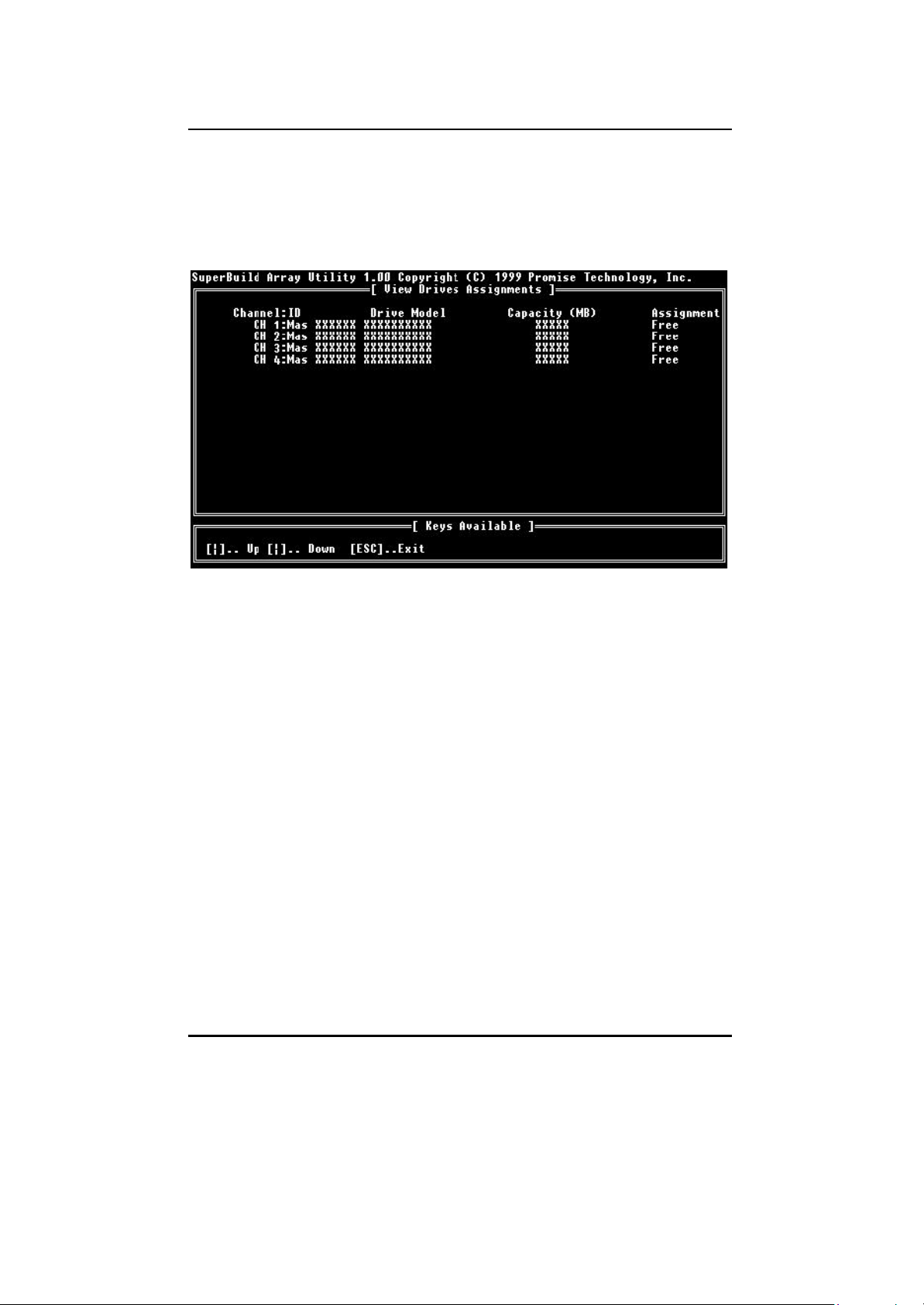
3.4 View Drive Assignments
By pressing [2] on the “Main Menu” screen, the “View Drive Assignments” screen
is displayed (below). This screen does not allow modifications to any of the four
fields.
Figure 8: View Drive Assignments screen
Channel: ID
This field shows the SuperTrak66 controller channel ID (1-4) to which a
particular drive is attached.
Drive Model
This field identifies the manufacturer, model, and model number (if
applicable) of each drive installed on the SuperTrak66 card.
Capacity (MB)
This field reflect s the capacity in MB (megabytes) of each drive.
Assignment
This field identifies the array to which each drive belongs. Assigned drives
are labeled with their disk array (1,2,3, etc...). Unassigned drives are
labeled “free,” and are considered "hot spares" to provide fault tolerance.
Unassigned drives may also be used to create a new array at any time.
- 21 -
Page 33
SuperTrak66™ User's Manual Chapter 3
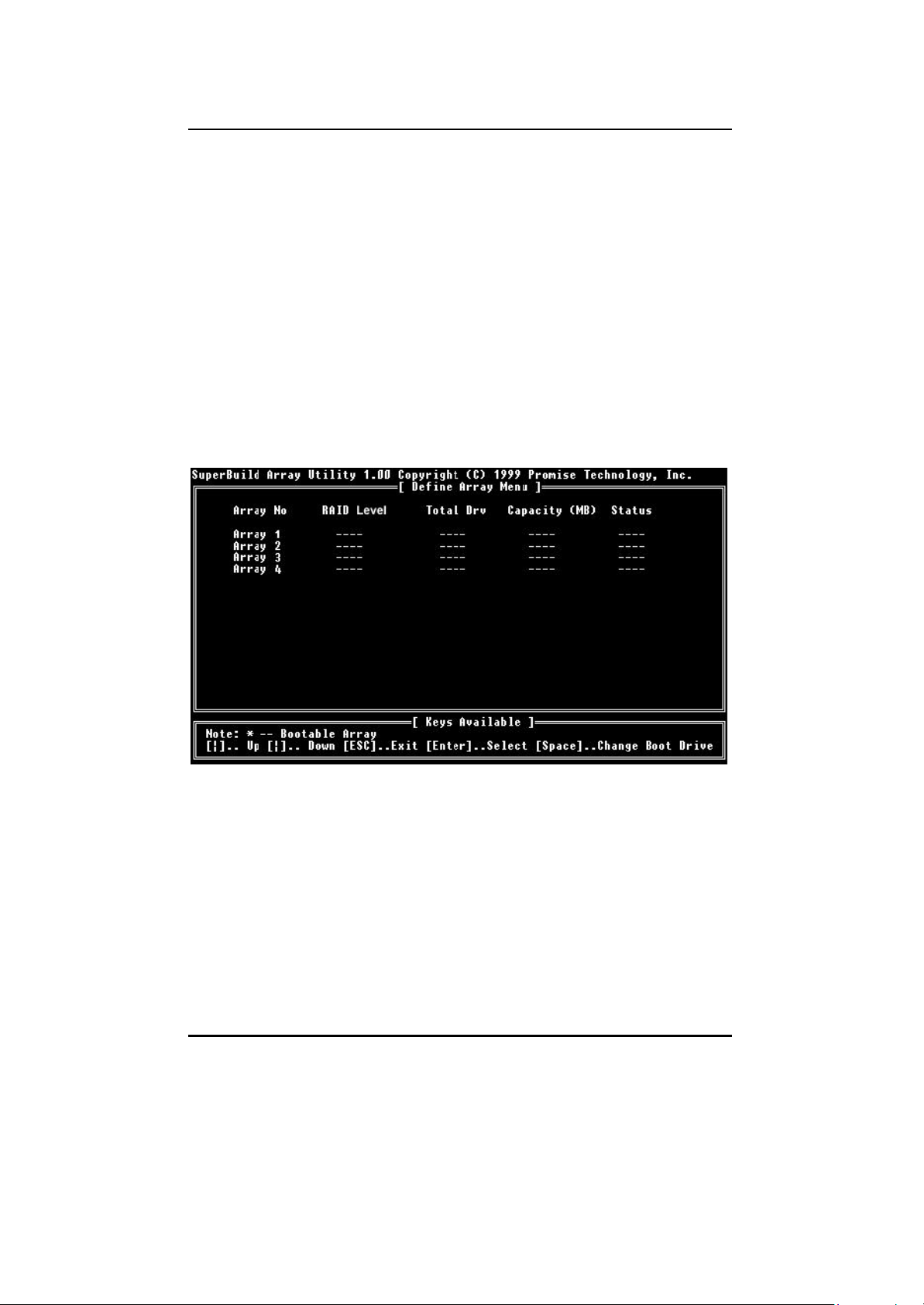
3.5 View / Define Array
By pressing [3] from the “Main Menu” screen, the “Define Array Menu” is
displayed (see Figure 9 below). There may already be existing arrays configured on
this screen or it may appear as indicated in the figure below. The Define Array
screen allows users to manually begin the process of defining both drive elements
and RAID levels for each disk array. Users will commonly create one or two drive
arrays with SuperTrak66.
To manually create arrays from the Define Array Menu below, use the arrow keys
to highlight an array number you wish to define, and press [Enter] to select. The
Define Array Definition Menu will next appear that allows drive assignments to the
disk array (see p.23).
NOTE: Promise recommends that if you are creating a single array using
SuperTrak without a "hot" spare drive, do so through the “Auto setup” screen
under selection [1] of the Main Menu.
Figure 9: Define Array Menu screen
Array No.
The Array Number column displays all arrays (defined or undefined)
addressable by the SuperTrak66.
RAID Level
This column indicates the RAID type applied to a particular array.
Total Drv
This column displays the number of drives configured for array.
- 22 -
Page 34

SuperTrak66™ User's Manual Chapter 3
Capacity (MB)
The values in this column reflect the total capacity in MB (megabytes) for
that array.
Status
This column displays the state information for each array. Status
definitions can be found at the beginning of Section 3.2.
Define Array Definition Menu
Selecting an Array # from the Define Array Menu brings up the Define Array
Definition Menu screen (see Figure 10 below).
You must first assign the type of RAID Level you want. In the Definition Menu
section, use the [Space] key to cycle through array types: RAID 0 (Striping), RAID
1 (Mirroring), RAID 3 (Stripe Data + Parity), RAID 5 (Data/Parity Striping) or JBOD
(Spanning). See Chapter 5 about RAID levels.
NOTE: Promise recommends the use of identical drives when creating a new array
for best results.
Figure 10: Define Array Definition Menu screen
- 23 -
Page 35

SuperTrak66™ User's Manual Chapter 3
Creating a RAID 0 Array
In the Definition Menu section (see Figure 10), use the [Space] key to cycle
through array types and select "RAID 0" for RAID Level. You will be joining the
drives you assign to this array together and splitting (or striping) data writes among
the members of the array. Each member of such an array will no longer be
readable as an independent drive if removed from the array. The capacity of the
array will equal the capacity of the smallest drive multiplied by the number of drives
within the array.
Changing Stripe Block Size
For RAID 0 arrays, SuperTrak66 will allow you to change the stripe block
size. The default is 64K. However, certain application environments may
perform optimally with different values (see drive manufacturer for additional
information on block sizes). To change the block size, use the arrow keys
to highlight the field and the spacebar to cycle through the available size
selections.
Assigning Drives to a RAID 0 Array
Under the [ Drive Assignments ] section, highlight a drive and, with the
[Space] bar, change the Assignable option to “Y” to add the drive to the
disk array. Press <Ctrl-Y> to save the disk array information. The initial
Define Array Menu screen will appear after you have pressed [Ctrl-Y]. You
will see the array defined. You may select another Array number to define
OR you may ESC to exit and return to the Main Menu of SuperBuild.
Creating a RAID 1 Array
In the Definition Menu section, use the [Space] key to cycle through array types
and select "RAID 1" for RAID Level. You will be creating two drives or two pairs of
striped drives (4 drives total) with identical data on them. The capacity of the array
will be half that of the total number of mirrored drives within the array. No stripe
block size option is available when mirroring 2 drives. In a 4- drive RAID 0+1 array,
you can set the stripe size for the two pairs of striped drives.
If you are creating a Mirroring array containing two drives only, you will use either
two brand new drives, or one drive that contains existing data and a second drive
that you wis h to mirror data. There is an additional window that will appear in order
to create such an array.
Creating a Mirroring Array with Two New Drives
As described above, if you select a mirroring array and wish to use two
new assigned drives, follow the directions here. Under the [ Drive
Assignments ] section, assign both new drives to the array and save the
information with <Ctrl-Y>. The following window will appear in order to
create the array. Confirm “N” or “Create Only” to the message shown in
order to proceed.
- 24 -
Page 36

SuperTrak66™ User's Manual Chapter 3
Figure 11: Two -Drive Mirroring Dialogue Window
Once the process is complete, you will be returned to the [ Define Array ]
menu where the array will be shown as defined.
NOTE: you may choose to attach an unassigned third drive to
SuperTrak66 to act as a "hot spare” replacement (see p. 28 ).
Creating a Mirroring Array with an Existing Data Drive
SuperBuild will create a mirrored array using an existing drive with data. In
the [Drive Assignments ] section, you must assign the existing data drive
and another drive of the same or larger capacity to the Mirroring array.
Press [Ctrly-Y]. Create the array by confirming “Y” or “Create and
Duplicate” to the message window that appears (same message as in
Figure 10 above):
You will be prompted to select the Source drive from the two available
drives. Arrow down to the drive that has existing data to be mirrored and
press [Enter] to select at the message window below:
Figure 12: Source Disk Window for Mirroring Existing Data
When prompted, press Y to confirm Yes to start duplicating the existing
source data to the target drive. NOTE: all target drive data will be erased.
Make sure you choose the correct drive.
After the process is complete, SuperBuild will ask you to reboot the
system. You may then return to the [ Define Array ] Menu to create an
additional array.
NOTE: you may choose to attach an unassigned third drive to SuperTrak
to act as a "hot spare” replacement (see p. 28).
- 25 -
Page 37

SuperTrak66™ User's Manual Chapter 3
Assigning Four Drives to a Mirroring Array
Under the [ Drive Assignments ] section, assign all drives to the array and
save the information with <Ctrl-Y>. SuperBuild will automatically create
two striped pairs of drives (RAID 0+1). You will be returned to the [ Define
Array ] Menu where the array will be shown.
Creating a RAID 3 Array
Use the information in Chapter 6 to help determine the selection of a RAID 3 array.
In the [Define Array Definition Menu], use the [Space] key to cycle through array
types and select "RAID 3" for RAID Level. You must configure such an array using
a minimum of three drives since additional parity information must be calculated
and stored on a dedicated "parity" drive.
You will be joining either two (if 3 drives are assigned) or three (if 4 drives are
assigned) of the drives together and splitting (or striping) write data among them.
Each member of such an array will no longer be readable as an independent drive if
removed from the array. The capacity of the array will equal the capacity of the
smallest drive multiplied by the total number of drives assigned to the array minus
one.
NOTE: If you choose to use just three drives, a fourth unassigned drive can be
your "hot" spare drive in case of drive failure (see p. 28).
Changing Stripe Block Size for RAID 3 Array
For RAID 3 arrays, SuperTrak66 will allow you to change the stripe block
size. The default is 64K. However, certain application environments may
perform optimally with different values (see drive manufacturer for additional
information on block sizes). To change the block size, use the arrow keys
to highligh t the field and the spacebar to cycle through the available size
selections.
NOTE: you can not change the block size AFTER the array has been
created.
Assigning Drives to a RAID 3 Array
Under the [ Drive Assignments ] section, highlight a drive and with the
[Space] bar change the Assignable option to “Y” to add the drive to the
disk array. Press <Ctrl-Y> to save the disk array information. The initial
Define Array Menu screen will appear after you have pressed [Ctrl-Y]. You
will see the array defined. You may ESC to exit and return to the Main
Menu of SuperBuild.
- 26 -
Page 38

SuperTrak66™ User's Manual Chapter 3
Creating a RAID 5 Array
Use the information in Chapter 6 to help determine the selection of a RAID 5 array.
In the Definition Menu section, use the [Space] key to cycle through array types
and select "RAID 5" for RAID Mode. You must configure such an array using a
minimum of three drives because of parity data generation.
You will be joining either two (if 3 drives are assigned) or three (if 4 drives are
assigned) of the drives together and splitting (or striping) data written among them.
Each member of such an array will no longer be readable as an independent drive if
removed from the array. The capacity of the array will equal the capacity of the
smallest drive multiplied by one less than the total number of drives assigned to the
array.
NOTE: If you choose to use just three drives, an unassigned fourth drive can be
your "hot spare” drive in case of drive failure (see p. 28).
Changing Stripe Block Size for RAID 5 Array
For RAID 5 arrays, SuperTrak66 will allow you to change the stripe block
size. The default is 64K. However, certain application environments may
perform optimally with different values (see drive manufacturer for additional
information on block sizes). To change the block size, use the arrow keys
to highlight the field and the spacebar to cycle through the available size
selections.
NOTE: you can not change the block size AFTER the array has been
created.
Assigning Drives to a RAID 5 Array
Under the [ Drive Assignments ] section, highlight a drive, and, with the
[Space] bar, change the Assignable option to “Y” to add the drive to the
disk array. Press <Ctrl-Y> to save the disk array information. The initial
Define Array Menu screen will appear after you have pressed [Ctrl-Y]. You
will see the array defined. You may ESC to exit and return to the Main
Menu of SuperBuild.
Creating a Spanning Array
In the [Define Array] section, use the [Space] key to cycle through array types and
select "JBOD" for RAID Level. You will be joining the drives you assign to this array
together as a single "virtual" drive grouping. Data will be stored to the first drive until
it is physically full. SuperTrak66 then will save data on to the next drive in
sequence. Each member of an array will no longer be readable as an independent
drive if removed from the array. The capacity of the Spanning array will equal the
total capacity of all drives assigned.
- 27 -
Page 39

SuperTrak66™ User's Manual Chapter 3
NOTE: Since spanning uses the full capacity of each assigned drive, different
capacity drives may be used without adversely affecting the performance of the
array. No other RAID benefits are provided (see Chapter 6).
Assigning Drives to a Spanning Array
Under the [ Drive Assignments ] section, highlight a drive, and, with the [Space] bar,
change the Assignable option to “Y” to add the drive to the Spanning array. Press
<Ctrl-Y> to save the disk array information. The initial Define Array Menu screen
will appear after you have pressed [Ctrl- Y]. You will see the array defined. You may
press the [ESC] key to exit and return to the Main Menu of SuperBuild.
"Hot" Spare Drives
Any extra drive that is not assigned to a fault tolerant disk array (RAID 1, 3, or 5)
will be recognized as a Spare Drive. In Figure 10 on page 23, the fourth drive shown
is unassigned and would be used as a hot spare for this RAID 3 array. Such a drive
is automatically added to an array once a disk member of the array has been
detected as “failed.” To restore fault tolerance as quickly as possible,
SuperTrak66 begins to perform an automatic data rebuild on the “spare” drive in
the background without the need to restart the system. At a later time, the failed
drive can be physically removed and an extra drive added in its place to function as
the “spare” drive.
Setting a Disk Array As Bootable
You may select which defined array will be used as the bootable array from the
[ Define Array ] menu (Item [3] in the Main Menu). Highlight the desired array and
press the [Space] bar key. The system will now recognize this as the first array
and an * asterisk will appear next to the array number indicating it as bootable (see
Figure 13 below).
NOTE: Your PC or server must be configured to use SuperTrak66 as the bootable
controller. The system will then use the bootable array as the (fixed) boot C: drive.
- 28 -
Page 40

SuperTrak66™ User's Manual Chapter 3
Figure 13: Assigning Bootable Array
Disk Array Recognition Order
During startup, the disk arrays on the SuperTrak66 are recognized in this order:
1) The array set to bootable in the SuperBuildTM setup
2) By the Array number (i.e. Array 1, Array 2…). This would be involved in
determining which drive letters will be assigned to each disk array.
Saved Disk Array Information
NOTE: Promise suggests that users record their disk array information for future
reference.
All disk array data is saved within the reserved sector of each arrayed drive.
Another feature of the SuperTrak66 disk array system is to recognize drive
members even if drives are moved to different IDE channels on SuperTrak66. Since
each drive’s array data identifies itself to the array, it is possible to reorder the
drives without modifying the array setup. This is valuable when adding drives, or
during a rebuild.
3.6 Delete Array
By pressing [4] from the “Main Menu” screen, the “Delete Array Menu” screen is
displayed (see below).
- 29 -
Page 41

SuperTrak66™ User's Manual Chapter 3
Figure 14: Delete Array Menu
NOTE: Deletion of an existing disk array could result in the loss of all dat a from
the hard drives of the affected array. Record all array information, including array
type, disk members, and stripe block size, in case you wish to undo a deletion.
Arrays may possibly be recovered after deletion by immediately re-defining the
array with information identical to the original configuration.
To delete an array, highlight the Array you wish to delete and press the [Del] key.
Confirm yes to the following warning (see Figure 15 message using the <Ctrl-Y>
keys to continue array delete. Press any other key to Abort the deletion process.
Figure 15: Delete Array Dialogue Box
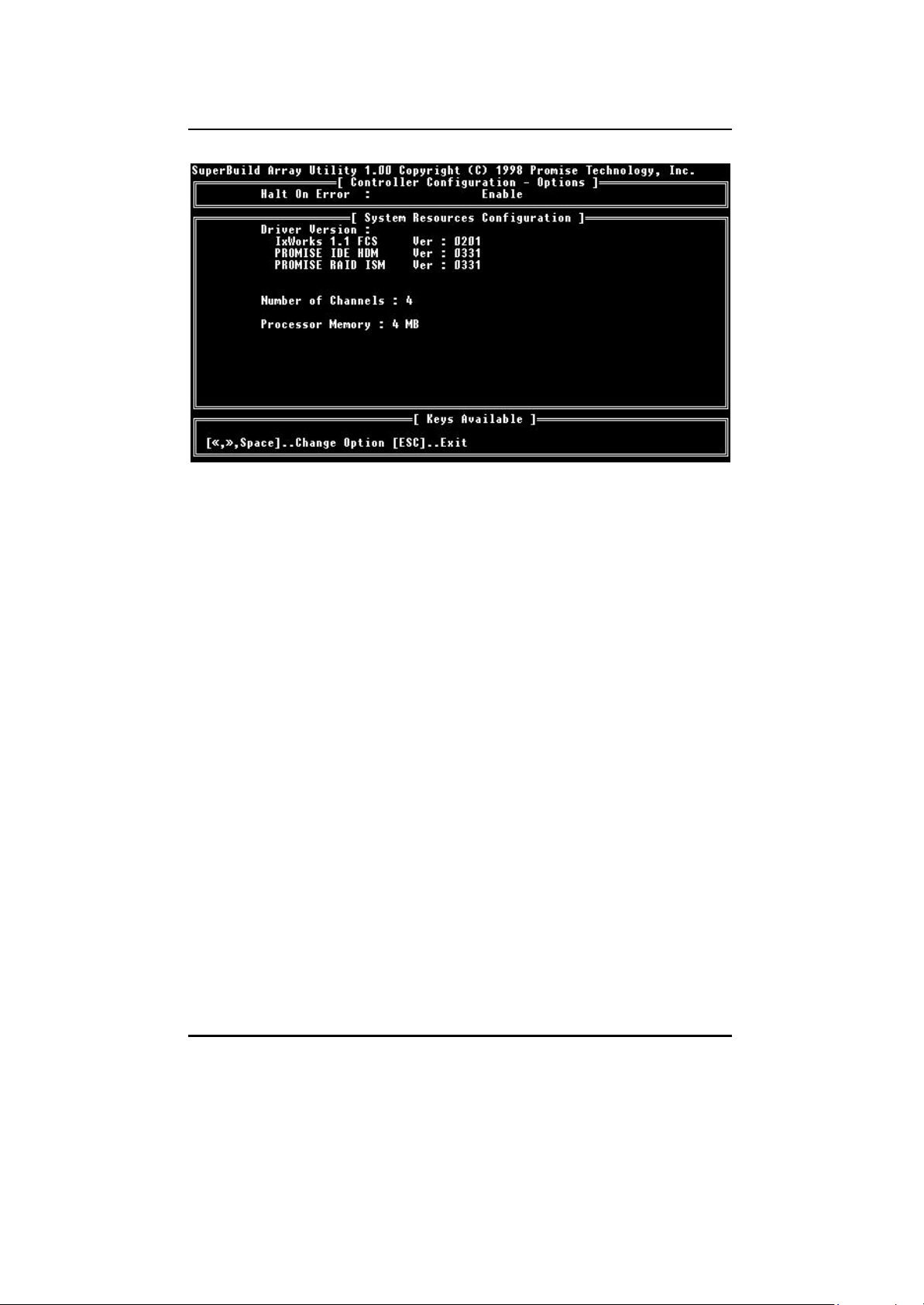
3.7 Controller Configuration
By pressing [5] on the “Main Menu” screen, the “Controller Configuration” screen
will appear (see below).
- 30 -
Page 42
SuperTrak66™ User's Manual Chapter 3
Figure 16: Controller configuration screen
This screen allows you to modify the “Halt On Error” option (enable/disable) by
pressing the spacebar. “Halt On Error” is enabled if you want the system to halt
pro cessing during bootup if the SuperTrak66 BIOS determines that there is an
array error. All other information in the System Resources Configuration section is
for display only. The information presented here is as follows:
Driver Version
Shows the driver software version of the IxWorks operating system,
Promise Hardware Driver Module (HDM), and Promise Intermediate
Software Module (ISM).
Number of Channels
Shows the number of channels attached to the SuperTrak66 controller
which may be used to connect one drive each for use in RAID arrays.
Processor Memory
Shows the size of the SIMM plugged into the SuperTrak66 controller card.
- 31 -
Page 43

SuperTrak66™ User's Manual Chapter 4
SuperCheck™ Setup
SuperCheck™ is Promise Technology’s array and system monitoring utility. With
SuperCheck, you can monitor you’re arrayed hard drives, rebuild arrays, and
check the operation of server-level components (fans, etc.). There are four basic
softwa re components to SuperCheck: the Message Server, the Message Agent,
the I2O driver, and the SuperCheck Monitoring Utility.
Before moving on to the actual installation process, we will describe where
SuperCheck components should be installed in a typical network, what hardware
they should be associated with, and what function each component performs.
Figure 17 : Typical SuperCheck Component Installation
- 32 -
Page 44

SuperTrak66™ User's Manual Chapter 4
A typical installation of the SuperCheck software components on a network might
look like Figure 17 on page 32. The major elements of this network are (from top to
bottom):
− Remote Monitoring Stations (via Internet)
− Main Network File Server (with direct I nternet access via a Firewall)
− Internal SuperTrak stations (connected via Intranet/LAN)
− Internal Monitoring Station
As shown, different components of SuperCheck are installed on each of the
network elements.
(1) SuperCheck Utility - The SuperCheck Monitoring Utility (the GUI that you will
be using) may be installed on any system element with a TCP/IP connection
where you want to perform monitoring. As shown in Figure 17, the SuperCheck
utility is installed on the main File Server, on both SuperTrak66 stations, on
two remote systems over the Internet, and on one internal system. NOTE: For
security reasons, array maintenance features can only be performed at the
actual server location of a SuperTrak66 array and are unavailable at all other
consoles.
(2) Message Server - The Message Server software component serves as the
main link between all SuperTrak arrays residing on the network, the internal
Intranet/LAN (via TCP/IP protocols), and remote monitoring stations
communicating via the Internet. For remote Internet monitoring, the Message
Server component must be installed on a machine with an unique IP address
that is visible to the Internet (as in our example). From its central
communications position, the Message Server software interfaces with all
SuperTrak arrays located on the LAN and allows all system elements (with the
GUI installed) to see those arrays. The File Server where the Message Server
software is installed may or may not house a SuperTrak array. In our example
on Figure 17 , it does not. One reason may be that the File Server is not
running Windows NT 4.0.
(3) Message Agent - The Message Agent software component must be installed
on each file server that will house a SuperTrak array. The Message Agent
communicates with both the Message Server and the SuperTrak66 controller.
Installing the Message Agent automatically installs the I2O device driver. NOTE:
All stations containing SuperTrak66 must be running Windows NT 4.0.
Maintenance on SuperTrak arrays can be performed only using these stations .
(4) I2O Device Driver – Installed automatically with the Message Agent, the driver
allows the station to communicate directly between the Promise SuperTrak
controller card and Windows NT. This permits Windows NT to recognize RAID
arrays attached to it.
- 33 -
Page 45

SuperTrak66™ User's Manual Chapter 4
4.1 SuperCheck Installation
SuperCheck has many component modules, which, depending on your scenario,
may or may not need to be installed on your system. The following “Installation
Scenarios” describe what components are to be installed, and where.
Installation Scenarios
The following installation scenarios each detail a separate software installation
model. Some scenarios are based on a single system, while others involve multiple
systems on a LAN or WAN. Select the scenario(s) which best match your needs,
then follow the installation steps listed for that scenario. Each of these components
may be installed by following the “Common Components” installation procedure
outlined on p.36 . Proceed to section 4.2 once installation is complete to begin
“SuperCheck Administration.”
NOTE: All systems with the SuperTrak66 controller will require the Message Agent
software (includes automatic installation of the I2O device driver). Additionally, the
component installations that follow require TCP/IP to be already properly installed
on the server system. Chapter 2 contains some information about installing
TCP/IP on Windows NT.
NOTE : While you may install multiple systems with the Message Server software,
Promise recommends against it because the same SuperTrak arrays will be
visible from every instance of the Promise Message Server, causing confusion.
All Scenarios:
1) If the system is on a LAN or WAN, use the IP address for which your
TCP/IP is already configured to establish connections. Otherwise, use
IP address 127.0.0.1 for all your TCP/IP configurations; This address
will allow all TCP/IP requests to remain within the system.
2) Install the Message Agent on the station with SuperTrak66
(automatically installs I2O driver component).
3) Reboot the system AFTER all software components have been
installed in order to activate any installed NT services.
To access a SuperTrak system locally
1) Install the Message Server on to this system.
2) Install the Monitoring Utility onto this system.
- 34 -
Page 46

SuperTrak66™ User's Manual Chapter 4
To access a SuperTrak system remotely across a LAN
1) Install the Message Server software on to one (or more) systems on
the LAN. The system(s) chosen for the Message Server may also
include a SuperTrak66 station, be an independent station on the LAN,
or act as a network server for the LAN. All Message Agents connected
on this LAN will be visible from each instance of the Message Server.
2) Install the SuperCheck Monitoring Utility software on to each LAN
station from which you wish to monitor the SuperTrak66 array(s).
When you begin SuperCheck, you will need to perform “Adding a New
Message Server” for each Message Server installed in step 1 that you
want to monitor.
To access a SuperTrak system remotely on a WAN
1) If you have not done so already, install a Promise Message Server on
a system on the LAN. The system chosen for the Promise Message
Server installation may house a SuperTrak66, be an independent
station on the LAN, or house a network server for the LAN. For remote
Internet monitoring, the Message Server component MUST be installed
on a machine with an unique IP address that is visible to the Internet.
All Message Agents connected on this LAN will be visible for each
instance of the Promise Message Server.
2) Install the SuperCheck Monitoring utility on to each remote station
where the SuperTrak system will be monitored. When you begin
SuperCheck, you will need to “Add a New Message Server” for the
Promise server installed in Step 1 that you wish to access.
3) If the WAN to which the Monitoring utility will be connected has any
firewall protection measures, you must open the IP address for the
system (or systems) containing the Promise Message Server software
in order to connect to them over Internet/WAN. TCP/IP port number
710 and 711 are used by the Message Agent to accept in-bound
connections.
- 35 -
Page 47
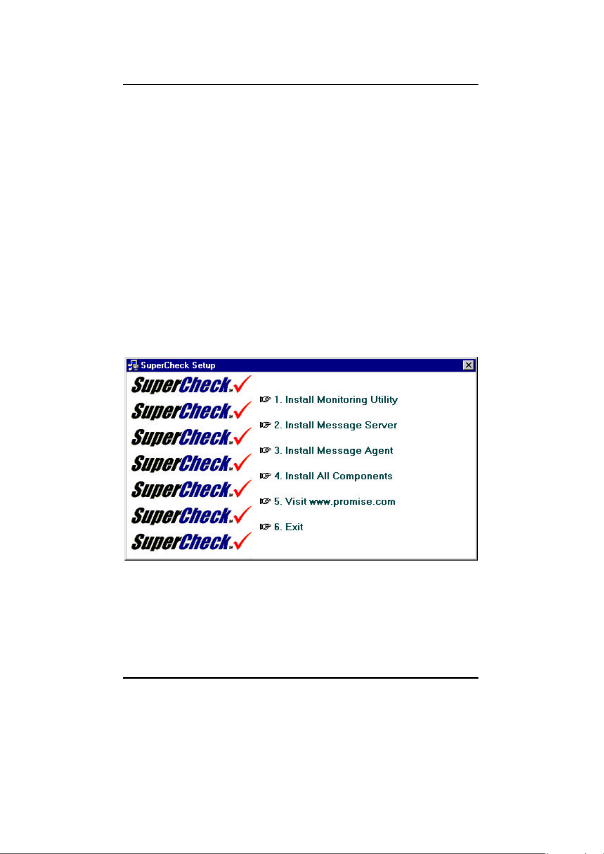
SuperTrak66™ User's Manual Chapter 4
Common Component Installation
This section outlines the installation procedure for a component of the SuperCheck
software package. See the installation scenarios outlined in section 4.1.1 to
determine which components to install.
NOTE : If you are re-installing SuperCheck, you must first stop the services for the
Message Server and Message Agent for installation to work.
For each component to be installed, do the following:
1) Insert the SuperCheck Install Diskette Number 1 into the floppy drive.
2) From Windows NT, go to the Start button, and click on “Run…” from the Start
Menu.
3) Type in:
A:\setup.exe↵
4) The main SuperCheck component installation menu will come up as seen
below.
Figure 18 : SuperCheck component installation menu
5) Select a software component from the menu by clicking it.
- 36 -
Page 48

SuperTrak66™ User's Manual Chapter 4
6) When the “Choose Destination Location” window (see Figure 19 below)
comes up, choose a directory to install this component.
7) Click “Browse” to select a Destination folder on your system other than the
folder suggested by default. Click the “Next” button to accept the location
selected.
Figure 19: “Choose Destination Location” window
- 37 -
Page 49

SuperTrak66™ User's Manual Chapter 4
8) The “Select Program Folder” window comes up next, shown in Figure 20
below. Choose a Start menu folder to list this item under by entering a folder
name, and selecting a “parent” folder from the list under which this new
folder’s contents will reside. Click the “Next” button to proceed.
Figure 20 : “Select Program Folder” window
- 38 -
Page 50

SuperTrak66™ User's Manual Chapter 4
9) The “Start Copying Files” window will then be displayed (see Figure 21 below).
Verify that the proper component(s), destination folder, and program folder you
selected for installation are correct, then click on “Next” to proceed. If
otherwise, click the “Back” button to go back and make changes.
Figure 21: “Start Copying Files” window
10) When you see the “Setup Needs the Next Disk” pop -up window (see Figure
22 below), insert the SuperCheck install diskette number 2 in the floppy drive.
Click on the “OK” button when it is ready. [You may use the “Browse”
button if your installation software resides anywhere other than the floppy
diskette to choose the correct source location.]
- 39 -
Page 51

SuperTrak66™ User's Manual Chapter 4
Figure 22 : “Setup Needs the Next Disk” pop-up window
11) When the installation is complete, you will see the “Setup Complete” window.
Click on the “Finish” button to complete the install process for this component
and restart your system.
- 40 -
Page 52

SuperTrak66™ User's Manual Chapter 4
4.2 SuperCheck Administration
Once installation is complete, you may begin using the SuperCheck utility. There
are still a few things that need to be configured before your SuperCheck install and
administration are complete. This section will outline tasks necessary to complete
SuperCheck Administration. See section 4.3, “SuperCheck Task Quick
Reference” for details on executing each task. Please refer to Chapter 5 for a
complete visual technical reference of the SuperCheck utility.
After you have reviewed and implemented each task below, your SuperCheck
installation will be complete. At this point, you will be ready to use your
SuperTrak66 RAID server for workload I/Os. Configure your array(s) for operation by
partitioning and formatting them under the standard Windows NT “Disk
Administrator .”
Creating Message Servers & Agents
The first time you run SuperCheck, there will be no Message Server, Message
Agent, or array attachments. To establish the server connections, you must
determine the TCP/IP address of the system that is running the SuperTrak66
Message Server. You may need your LAN administrator to provide this information.
See Section 4.1 for installation scenarios to determine where the Message Server
should be installed. Once you have identified the Message Server, perform the
“Create a new message server” task as detailed in the SuperCheck Task Quick
Reference, based on the Message Server system’s IP information.
Once the Message Server has been connected successfully, double -click on the
Message Server icon to expand the hierarchical tree to show all attached Message
Agents. Log into an attached Message Agent for access to the particular
SuperTrak66 system under the Agent’s control.
Adding/Deleting New Use rs
If additional users require access to a SuperTrak66 Message Agent, the system
administrator must create a "new user" under the Message Agent. Each user may
be given access to various levels of control by an admin. A
“User / Administrator” may create/delete other user accounts. “Array
Administration” and “Adapter Maintenance Rights ” boxes allow access to specific
functions of the system.
NOTE: Don’t forget to set a password for any user who has anything more than
viewing privileges on a secure network.
Setting Up A New Array
Setting up an array is considered a simple task. Consideration should be given as
to the type and configuration of the array. Please see Chapter 6 for RAID
configuration ideas and then perform the task of creating the new array (see p. 16)
- 41 -
Page 53

SuperTrak66™ User's Manual Chapter 4
Array Administration
Array administration is the ability to create, view, modify and delete arrays. The
ability to view the status of an array through the utility allows identification of
problems which may require user intervention to prevent the array from going down
or to restore fault tolerance.
NOTE : Actual maintenance of the array (deleting, rebuilding, creating, etc…) may
be performed only from the system housing the SuperTrak array for security
reasons. SuperTrak greys out the maintenance functions for monitoring stations.
The I/O information (IOP or Controller) subpanes (see page 84) of SuperCheck
allow you to see that all drives are functioning correctly. If any drive has failed,
SuperCheck will indicate which drive(s) has failed. You also can see the array
status to determine if it is functioning, or if it requires critical attention, or if it has
begun an automatic rebuild, etc. The array page allows modification of the cache
settings for fine -tuning your server’s performance. The enclosure pane allows you
to verify that the drives are operating within temperature specification, and that the
enclosure cooling fans are operational.
NOTE: Never delete an array unless you have backed up all data which is needed
on the array. It may be possible to restore access to an array after the deletion by
r e-creating the array exactly as it was defined previously. Though the product allows
for this procedure, Promise does not recommend it.
Changing the cache settings will directly affect performance of an array. One way
of determining the cache settings whi ch are appropriate for your SuperTrak66 is to
use a benchmarking utility. Such a utility stresses the array in a manner
consistent with expected typical workload for the array. Choose a configuration that
yields the best performance results. It is difficult to make any solid
recommendations for cache settings since the array workload will differ from
system to system depending on its application.
Setting Up Email Notification
SuperCheck allows the administrator or user to check on array status at anytime.
You can also set up e-mail notification so that SuperCheck will notify you of any
problems via e-mail messaging services. The notification feature is recommended
for any type of array which is to be accessible over a network.
NOTE: E-mail alert notification is Message Agent -based, not array-based. You will
receive e-mail notification for problems related to all arrays connected under the
Message Agent.
The e- mail alert notification may be adjusted for each Message Agent to only send
messages for a particular list of events. The administrator can add or remove
events from the e-mail alert notification as desired.
- 42 -
Page 54

SuperTrak66™ User's Manual Chapter 4
Identifying Problems
There are a variety of problems which can be detected by SuperCheck, allowing
you to possibly prevent a system crash or data loss due to a hardware problem.
The software can determine if an array member has failed, show whether the
housing temperature is within operational parameters, or identify a problem with the
housing cooling fans. If you experience any failures, please see the
Troubleshooting Guide in Chapter 7 for a recommended course of action.
- 43 -
Page 55

SuperTrak66™ User's Manual Chapter 4
4.3 SuperCheck Quick Reference
The following section is a listing of initial steps necessary to complete each task
during administration of a SuperTrak66 server system using the SuperCheck utility.
These tasks are not listed in any particular order, nor is this intended to be a
complete, step-by-step guide to setting up the software successfully. Please refer
to the previous section 4.2, “SuperCheck Administration," for details on what tasks
to execute for basic operations."
To Create A New Message Server
1) Right-click on the “MyConsole” icon located in the Tree View area of the
SuperCheck main menu (or left-click "MyConsole" from the pull- down
selections at the top of the main menu ).
2) Click on “New”, then “Server” in the expanded pop-up menu
3) In the message server Information View, enter “Label,” and “IP address”
information. If you are not sure of the server name, try just entering the IP
address.
4) Click the “Confirm” button. Once a new Message Server is created, it will
create a Message Agent icon automatically.
Creating A New User
1) Log into the Message Agent for which you would like to add a New User.
2) Right-click the “Users” icon in the Tree View area of SuperCheck Main
Menu. Then left -click on “New” and select “User” from the pop-up selection.
3) A “New User” icon will appear. Double-click on it to view the user
Information View.
4) Modify all the user information according to the desired access level for the
new user.
5) If the user has any level of administrative control, and the server is connected
to a WAN, make sure to set a password.
6) C lick the “Commit” button to update the user information.
- 44 -
Page 56
SuperTrak66™ User's Manual Chapter 4
Deleting an Existing User
1) Select the icon representing the user you wish to delete.
2) Right-click the icon and select “Delete” from the pop-up menu.
3) Choose “Yes” if this is a user you wish to delete.
NOTE: SuperCheck will not allow deletion of the last account with admin privileges.
This protects the admin from being locked out of the system and having to reinstall SuperCheck.
Accessing Message Agent
1) When clicking on any Message Agent (if you are not already logged into
the Agent), you will be prompted for password entry.
2) Enter the account/password for this system to access the Agent and to gain
access to the SuperTrak system.
3) Checking the “Save password” box will remember the password for this
Message Agent. Future accesses to this Message Agent from this terminal
w ill not require password input.
4) Click “OK” to submit the password and access the Message Agent.
Creating a New Array
1) Select the IOPx (or Controller) icon on which you want to create an array.
2) Right-click the icon. Click “New”, then select “Array” from the pop-up menu.
3) Enter the pertinent information in the “Name,” RAID Level” and “Block Size”
fields. (Available RAID level selections are based on number of drives to be
used; Block Size is selectable from a pull-down list or use the default 64K)
4) A new array icon will be created in the Tree View, titled with the text
entered into the “Name” field.
5) Drag and drop any unassigned drive icon on top of the array icon which
you have just created in order to add the drive to the array (unassigned drive
icons do not have a red arrow in the upper left corner). Hard drive(s) will then be
assigned to the array in the order that they are dragged on to the array icon.
6) If you incorrectly selected the wrong disk for the array at this time, simply
highlight that disk in Tree View, right-click the mouse, and select Delete from
the pop-up menu. The disk will be removed from this array.
7) Repeat step 5 until the array is completed.
8) Press the “Commit” button and reboot the Operating System for a new array.
- 45 -
Page 57

SuperTrak66™ User's Manual Chapter 4
Deleting an Existing Array
NOTE: Deleting an array may result in the loss of all data contained on it. Be sure
to back up any needed data before deletion.
1) Select the icon of the array you wish to delete
2) Right-click the icon and choose “Delete” from the pop-up menu.
3) Cl ick the “Yes” button if this is an array you wish to delete. Reboot.
Setting Up E-mail Alert Notification
1) Double- click on the Message Agent icon from where you want to receive
email alert notifications. This will reveal the Message Agent main screen.
2) Check the “Email alert on error” box in the Information View (if it is not already
checked).
3) Type in the SMTP server address for your mail server in the “SMTP server”
field. Your network administrator will have this information if you do not know it.
4) Click the “Change” button next to the input field to update SuperCheck
configuration for the SMTP server.
5) Next, set the email address for this machine. The Information View is located
below the "Email alert on error" pane. E-mail reports will seem to originate from
this address. Recipients of these messages may reply to this address.
6) Click on the “Change” button next to the input field to update SuperCheck
configuration for the Email ID.
7) Add users to the “Email Receiver List”.
Adding an User to an Email Receiver List
1) Double- click on the Message Agent . Add any new user(s) needed for
email alert notification. This will open the Message Agent main screen. Find
the Information View of the Message Agent screen.
2) If you have not already done so, set up email alert notification(s).
3) Under the “Email receiver list” segment of the Information View, type in the
email address(es) of the user you wish to receive email alert notification(s) in
the “Email address” field.
4) Click on the “Add” button to add any users to the list.
- 46 -
Page 58

SuperTrak66™ User's Manual Chapter 4
Removing an User From an Email Receiver List
1) Double- click on the Message Agent from which you wish to remove a
user for email alert notification(s). This will open the Message Agent main
screen. Find the Information View of the Message Agent screen.
2) Under the “Email receiver list” segment, select the email address in the
scrollbox which you wish to remove.
3) Click on the “Remove” button or press the Delete key to remove the address
from notification.
Adding/Removing Events to/from Email Alert Notification
1) Double- click on the Message Agent icon to change the alert email
notification events you wish to modify. This will open the Message Agent main
screen. Find the Information View of the Message Agent screen.
2) Select the event you wish to modify in the “Event” column.
3) Right-click on the “Email” column and select “yes” to have this event send
out an email notification. Select “no” to remove the item as an alert event.
4) When you are finished making changes, click the “Change” button next to the
event selection scrollbox to update the SuperCheck configuration for email alert
notification.
NOTE: The "Report" column is used for event reporting to the utility. Events may
be accessed by right-clicking the IOPx (controller) icon .
- 47 -
Page 59

SuperTrak66™ User's Manual Chapter 5
Using SuperCheck™
This section is an in-depth software functionality reference for the SuperCheck
RAID Manager. It contains step-by-step instructions on activating events, modifying
values, and executing all major tasks.
5.1 Main Window
Upon starting SuperCheck, the main window will be displayed. The figure below
shows an example of the entire hierarchical tree.
Figure 23 : SuperCheck utility main window
Along the left side of the window is the Tree View which originates with “Console”
and can display the entire SuperTrak66 system(s), down to individual hard drives
within arrays and server-level components (see Chapter 4 for details on each level).
At the top right corner is the Object View, which displays icons representing
lower- level devices that appear below the highlighted device in the Tree View.
The SuperCheck splash screen is displayed in the Information View of the
window (the lower right hand section of the window.)
- 48 -
Page 60

SuperTrak66™ User's Manual Chapter 5
Using Tree View
The Tree View can display every element of your SuperTrak66 system. This menu
behaves like the Tree View in Windows Explorer (Explorer shows logical drives and
folders, etc… in a hierarchical menu structure). You may also choose to expand or
collapse Tree View items, or hide/display the Tree View pane entirely.
Figure 24: Using Tree View
Expanding/Collapsing Tree View It ems
To open the items below a listed device, click once on the [+] to expand
the tree, [-] to collapse it. Double-clicking an item will not only cause the
tree to expand down, but will also add the sub-items as icons in the Object
View (see Figure 24 above).
Hiding/Displaying Tree View
Users may hide or show the Tree View pane of the SuperTrak66 Main
interface at any time. Navigation can be performed via the Object View
and/or pull-down menus. The hide/show function is accessed either by
right-clicking any icon in the Tree View and selecting “Hide” or “Show”.
The same function may be used with the pull-down menu with any icon
highlighted in Tree View (see Figure 24 above).
Renaming Displayed Levels
Users may rename the array and server names at the Tree View depending
on their administration rights.
The renaming function is accessed either by right -clicking the appropriate
icon in the Tree View and selecting “Rename” or by using the pull- down
menu with the appropriate icon highlighted in Tree View.
- 49 -
Page 61

SuperTrak66™ User's Manual Chapter 5
Console & Server level rights: no special user or administrative rights
are required since the name applies only to the user’s system.
Array & User level rights: requires administrative (password-protected)
rights since other Agents can see the array and potentially access the
levels.
Refreshing SuperTrak Monitoring
Users may manually refresh SuperTrak66’s display of the server
environment shown in Tree View at any time to immediately see system
changes anywhere in the network. The default refresh rate is once every 10
seconds.
The refresh function is accessed either by right -clicking icons in the Tree
View and selecting “Refresh” or by using the pull-down menu with the
appropriate icon highlighted in Tree View. It can also be accessed using
the F5 function key.
- 50 -
Page 62

SuperTrak66™ User's Manual Chapter 5
Using Object View
The device icons generated by a double-click in the Tree View will be
displayed in this portion of the window. Double-clicking an icon in the
Object View highlights the item corresponding to it in the Tree View and
changes the Object View to include any items directly connected to the
icon.
NOTE: Icons shown in this pane of the window which have a red “X” over
them represent an error or failed device.
Using Information View
The lower right portion of the SuperCheck main window is the Information
View. The Information View contains different items (text boxes, list boxes,
information fields and buttons), depending on which device is highlighted in
the Tree View.
Figure 25: Using Object View
Figure 26 : Using Information View
- 51 -
Page 63

SuperTrak66™ User's Manual Chapter 5
Using Status Bar
Figure 27: Using Status Bar
SuperCheck’s status bar is no different than any other Windows program. The
status bar is located just below the Main Window of SuperCheck and provides
status information of various administration functions such as (Ready, Rebuilding,
etc…). The Status Bar can be displayed or hidden using the View pull-down menu.
5.2 SuperCheck Pull-Down Menu/Toolbar
SuperCheck uses a context-sensitive pull-down menu and optional toolbar with
icons located at the top of the SuperCheck Utility Main Menu. They provide access
to all major SuperCheck management functions.
Using Pull- Down Menu Items
In addition to the options accessed from Tree View and the Information View, users
may access the same functions from pull-down menu selections located at the top
of the SuperCheck Utility Main Menu. The options available are context-sensitive
depending on which icon in the Tree View is highlighted (see example below).
Certain functions that are unavailable will appear “greyed out.” Directions on
implementing functions and options in this Manual are based on the Tree View
unless otherwise indicated.
Figure 28 : Array pull-down menu
- 52 -
Page 64

SuperTrak66™ User's Manual Chapter 5
Using View Pull-Down Menu
Figure 29: Using View Pull-Down Menu
By checking or unchecking items with the mouse, this pull-down menu selects or
deselects the appearance of the Toolbar icons, Status Bar, and/or Tree View
window.
Using Connection Pull -Down Menu
Figure 30 : Using Connection Pull-Down Menu
The Connection pull-down screen is available at all times regardless of which icon
is highlighted in the Tree View of the SuperCheck utility. From here, a user may
select from the following functions:
New Server
Creates a new server (see section 5.3 Console Functions on page 59)
Connect
Establishes a connection with an already -created SuperTrak66 server (see
section 5.3 Connecting The Message Server on page 61)
Disconnect
Temporarily halts the connection with a SuperTrak66 server (see section
5.3 Disconnecting A Message Server on page 61 )
- 53 -
Page 65

SuperTrak66™ User's Manual Chapter 5
Using Preference Pull -Down Menu
Figure 31 : Using Preference Pull-Down Menu
The Preference pull-down menu allows users or administrators to change the way
the SuperCheck Main Window is displayed:
Font
Selecting Font allows you to select a different font and/or font color to
display text
Background
Allows changing the color of the SuperCheck View panes.
Using Help Pull-Down Menu
Figure 32: Using Help Pull-Down Menu
Activated from the pull-down menu, the Help Menu allows users to access an
online help index of how-to topics and functions, provides the SuperCheck
version/build identification, and can activate a demonstration of all Main Window
screens.
About SuperCheck
Pull-down menu item provides information on the version and build number
of the SuperCheck utility.
Viewing Autodemo
A level-by-level automatic display of each screen in the SuperCheck Main
Window, starting at the Console level in Tree View. You may also cont rol
the Autodemo via the keyboard as follows:
- 54 -
Page 66

SuperTrak66™ User's Manual Chapter 5
Start/Stop AutoDemo press F12 key
Next Item press F10
Previous Item press F11
Using Help Topics
Activated from the pull- down menu or toolbar icon, online help offers information on
functions and how-to items accessible from the SuperCheck utility. There are two
major areas, Contents and Find.
Contents
Lists SuperCheck functions either by Interface Component (i.e. Tree View
level item or Information View Menus) or by how -to actions (Starting Up,
Managing Arrays, etc…)
Figure 33: Using Help Contents Window
- 55 -
Page 67
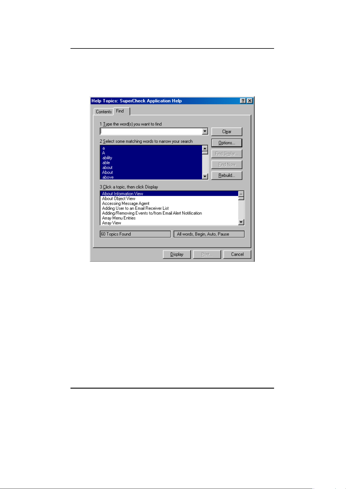
SuperTrak66™ User's Manual Chapter 5
Find
Creates a comprehensive index based on each word and topic found in the
Help file.
Figure 34: Using Help Find Window
- 56 -
Page 68

SuperTrak66™ User's Manual Chapter 5
Using SuperCheck Toolbar
Figure 35: Toolbar icons
Toolbar icons and their associated functions are available depending on which of
the items in the Tree View is highlighted as described in the descriptions below.
New Server: available when the Console icon is active. It allows the user to
create a New Server on the SuperTrak66 system. The user must have “User
Account Rights” (see p. 59 for details).
Connect Server: available when a particular Server icon is active. It allows
the user to recognize the Server on the SuperTrak66 system. The user must have
“User Account Rights” (see p. 61 for details).
Disconnect Server : available when the Server icon is active. It allows the
user to take the Server offline from the SuperTrak66 system. The user must have
“User Account Rights”. Disconnect is the only proper way to shut down the
SuperTrak66 server in order to perform physical maintenance. This also logs off the
Server from being recognized by any other SuperCheck monitoring utility online
(see p. 61 for details).
Rebuild Array : available when an Array icon for a RAID Level 1, 3, or 5 is
active. This begins the process of restoring data to a replaced drive from remaining
drives in the array. The user must have “User Account Rights” (see p. 91 for
details).
Synchronize Array: available when an Array icon for a RAID 1 or 0+1 level
array is active. This allows user to write data from primary mirrored drive(s) to
secondary mirrored drive(s) to assure both have identical data as a maintenance
procedure. The user must have “User Account Rights” (see p. 94 for details).
Delete Array : available when an Array icon is active. This allows the user to
delete the array from the SuperTrak66 system The user must have “User Account
Rights” (see p. 90 for details).
- 57 -
Page 69

SuperTrak66™ User's Manual Chapter 5
Create Array : available when an Message Agent icon is active. This allows
user to create a New Array on the SuperTrak66 system. The user must have “User
Account Rights” (see p. 80 for details).
Delete User: available when a User icon is active. This allows an
administrator to delete the user from SuperTrak66 monitoring/alert e- mail rights
access. Only administrators may delete an user (see p. 75 for details).
Create User: available when a Message Agent icon is active. This allows
the admin to create and add a new user to the SuperTrak66 system for
monitoring/alert e-mail. The user must have “User Account Rights” (see p. 66 for
details).
Start/Continue Button: available when Array icon is active. This allows
start/continuation of rebuild (see p. 94 for details) or array synchronization process
(see p. 95 for details).
Pause Button: available when Array icon is active. This allows pausing of
rebuild (see p. 94 for details) or array synchronization process (see p. 95 for
details).
Stop Button: available when Array icon is active. This allows
start/continuation of rebuild (see p. 94 for details) or array synchronization process
(see p. 95 for details).
About SuperCheck: provides information on the version and build number of
the SuperCheck interface (see p. 54 for details).
Help Button: loads SuperCheck’s Help contents and index. (see p. 55 for
details).
- 58 -
Page 70

SuperTrak66™ User's Manual Chapter 5
5.3 Console Functions
The SuperCheck “Console” in the SuperCheck utility main screen
represents the system from which you are monitoring your SuperTrak66
system(s). Its icon appears at the top of the Tree View (see below). When
this icon is highlighted, you may also access all Console functions from the
pull-down menus at the top of the main menu or context-sensitive menus enabled
by a right-click of the mouse.
Creating A New Message Server
1) Right-click on the “MyConsole” icon in the Tree View area of the SuperCheck
main menu (or left-click "MyConsole" from the pull -down selections at the top
of the main menu).
2) Left-click on “New” in the console menu, then choose “Server” in the pop -up
menu.
Figure 36: Creating New Message Server pull- downs
3) In the Message Server Information View (see below), enter “Label,” “Server
Name” and “IP address” information. If you are not sure of the actual Server
name, try just entering the IP address of the machine where the Message
Server is installed. Enter 127- 0-0-1 for a local machine connection.
4) Click the “Confirm” button.
- 59 -
Page 71

SuperTrak66™ User's Manual Chapter 5
Figure 37: Labeling New Message Server
Viewing Console Object icons
Once a Message Server has been created, double-clicking on the Console icon will
display the associated “Message Server” icon(s) in the Object View. These
represent the message server(s) connected to the SuperTrak66 console (see figure
below). Clicking on the server icon(s) will display the Information View screen for
the Message Server (see above).
Figure 38 : Console Object View
- 60 -
Page 72
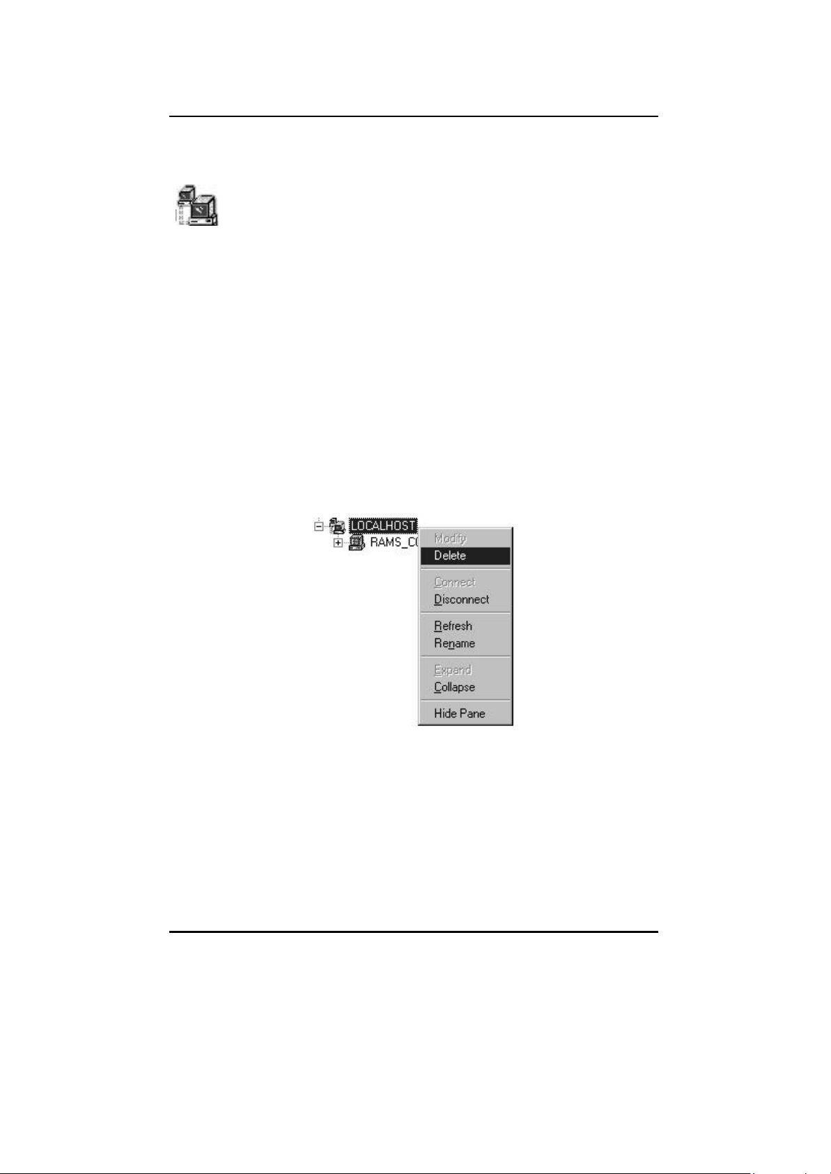
SuperTrak66™ User's Manual Chapter 5
5.4 Message Server Functions
The “Message Server” icon in the SuperCheck Tree View represents the
server that acts as a “gateway” into a particular SuperTrak Pro system.
The system may be composed of one server (the “gateway” server itself),
or multiple servers. Message Servers may or may not have a SuperTrak66
controller card and hard disk array installed. Once created, the Message Server will
automatically recognize all associated Message Agents that exist on the network.
Through the Message Server icon, users can delete a Message Server, and
connect/disconnect the Message Server from system. When this icon is
highlighted, you may also access all Message Server functions from the pull- down
menus at the top of the main window.
Deleting A Message Server
NOTE: If the server's designated IP address is changed because of a physical
move or system change, the Message Server must be deleted and a new Message
Server created with the new IP address and Server name.
1) Right-click on the “Message Server” icon in the Tree View area of the
SuperCheck main menu (or left-click "Server" from the pull-down selections at
the top of the main menu with the "Server" icon highlighted in Tree View).
2) Left-click on “Delete” in the pull-down/pop -up menu.
Figure 39 : Deleting Message Server pull-down
3) Click the “Confirm” button. The Server name and icon will be removed from the
SuperCheck Main menu screen. This change will take effect on the next
system reboot.
Disconnecting A Message Server
1) Right-click on the “Message Server” icon in the Tree View area of the
SuperCheck main menu (or left-click "Server" from the pull-down selections at
the top of the main menu with the "Server" icon highlighted in Tree View).
- 61 -
Page 73

SuperTrak66™ User's Manual Chapter 5
2) Left-click on “Disconnect” in the pull-down/pop -up menu.
Figure 40: Disconnecting Message Server pull-down
3) Click the “Confirm” button. The Server connection from the SuperTrak66 will
be taken "offline." This change will take effect immediately.
NOTE: Disconnecting the Server from the SuperTrak66 system prevents all
SuperCheck utilities from accessing data contained on the Server array(s). This
allows server maintenance to be performed but does not require deleting and recreating the Message Server data. This is also the only way to officially log out the
SuperTrak66 Server from the system. The utility will still see the Message Server,
but in a "disconnect" status.
Connecting The Message Server
1) To connect a Message Server that has been taken "offline", right -click on the
“Message Server” icon in the Tree View area of the SuperCheck main menu
(see below) or left- click "Server" from the pull-down selections at the top of the
main menu with the "Server" icon highlighted in Tree View.
2) Left-click on “Connect” in the pull-down/pop -up menu.
- 62 -
Page 74

SuperTrak66™ User's Manual Chapter 5
Figure 41: Connecting Message Server pull-down
Switching to Another Server
1) To connect to a Message Server in a different location, make sure the
Message Server icon is highlighted, then enter the IP address and label name
of the desired server in the Information View (see Figure 37 ).
2) Click the “Confirm” button. You will now be connected to another SuperTrak66
system location's Message Server and perform administrative functions
(assuming you have password authority).
NOTE: You wo uld switch Message Servers if the physical location of a Server or IP
address has changed.
- 63 -
Page 75

SuperTrak66™ User's Manual Chapter 5
Viewing Message Server Object icons
Double -clicking on the “Message Server” icon will display the SuperTrak66 system
server icons connected to the highlighted message server within the Object View
(see top of figure below). Clicking on the individual icons here reveals the Message
Agent Information View (see section 5.5).
Figure 42 : Message Server Information View
Viewing Message Server Information
In the Information View of the SuperCheck window, several text boxes will appear.
The fields for the Message Server Information View are defined as follows:
Label
In the “Label” text box, the name of the message server can be entered or
modif ied, and will be displayed within the Tree View.
Server Name
The “Server name” text box contains the internal operating system name
of the message server currently highlighted. This entry is obtained from the
server itself and cannot be modified.
- 64 -
Page 76

SuperTrak66™ User's Manual Chapter 5
IP Address
This series of four text boxes contains the IP address of the message
server currently highlighted. The IP address field is greyed out so you can
not change the IP address.
Version Information
This field contains information pertaining to the build version of SuperCheck
currently operating. This field cannot be modified.
Confirm / Reset
These buttons relate to the text boxes titled “Label,” “Server name,” and
“IP address”. Selecting “Confirm” saves the entries in these fields after
they have been modified. Selecting “Reset” clears the text boxes and
allows the user to modify old information.
- 65 -
Page 77

SuperTrak66™ User's Manual Chapter 5
5.5 Message Agent Functions
The “Message Agent” icon(s) in the SuperCheck utility main screen
represent the SuperTrak66 servers connected to the Message Server in a
particular SuperTrak66 system. There may be only one member in a
network (the server itself), or there may be additional servers connected (remote
systems). The Message Agent allows you to create new users, establish events for
notification, create e-mail addresses for notification, and schedule array
synchronization.
Accessing Message Agent
1) By clicking on any Message Agent icon in Tree View or Message Server
Object View (if you are not already accessing the Agent), you will be prompted
for password entry.
Figure 43: Setting Password screen
2) Enter the account/password for this system to access the Agent and gain
permission to the SuperTrak66 system.
3) Checking the “Save password” box will remember the password for this
Message Agent. Future access to this Message Agent from this terminal will
not require password input.
4) Click “OK” to submit the password and access the Message Agent.
NOTE: This Message Agent will remain accessible for the duration of the
SuperCheck session. Note: the utility will NOT automatically log out. You must
perform this manually.
Creating A New User
1) Log into the Message Agent for which you would like to add a New User.
2) Right-click the “Users” icon in the Tree View area of SuperCheck Main Menu.
Then left-click on “New” and select “User” from the pop-up selection (see
below).
- 66 -
Page 78

SuperTrak66™ User's Manual Chapter 5
Figure 44: Creating New User screen
3) A “New User ” icon will appear. Double -click on it to view the user Information
View.
4) Modify all the user information according to the desired access level for the
new user (see section 5.6 for more details on “User Rights”)
5) If the user has any level of administrative control, and the server is connected
to a WAN, make sure to set a password.
6) Click the “Commit ” button to update the user information.
- 67 -
Page 79

SuperTrak66™ User's Manual Chapter 5
Setting Up E-mail Alert Notification
1) Double- click on the Message Agent icon from where you want to receive email
alert notifications. This will reveal the Message Agent main screen. Find the
Information View of the Message Agent screen similar to below.
Figure 45 : Setting E-mail Alert box
2) Check the “Email alert on error” box in the Information View (if it is not already
checked).
3) Type in the SMTP server address for your mail server in the “SMTP server”
field. Your network administrator will have this information if you do not know it.
4) Click the “Change” button next to the input field to update SuperCheck
configuration for the SMTP server.
5) Next, set the email address for this machine. The email address section is
located below the "Email alert on error" pane. It appears below. E-mail reports
will seem to originate from this address. Recipients of these messages may
reply to this address.
Figure 46 : Setting Email ID window
6) Click on the “Change” button next to the input field to update SuperCheck
configuration for the Email ID.
5) Add users to the “Email receiver list”.
Adding an User to an Email Receiver List
1) Double- click on the Message Agent to which you wish to add a user for email
alert notification. This will reveal the Message Agent main screen. Find the
section of the Message Agent Information View screen similar to Figure 47 .
2) If you have not done so already, set up email alert notification.
- 68 -
Page 80

SuperTrak66™ User's Manual Chapter 5
Figure 47: Setting Email Address window
3) Under the “Email receiver list” segment of the Information View, type in the
email address of the user you wish to receive email alert notification in the
“Email address” field.
4) Click on the “Add” button to add this user to the list.
Removing an User From an Email Receiver List
1) Double- click on the Message Agent from which you wish to remove a user for
email alert notification. This will reveal the Message Agent main screen. Find
the Information View of the Message Agent screen similar to figure below.
Figure 48 : Removing User from E-mail alert
2) Under the “Email receiver list” segment, select the email address in the
scrollbox which you wish to remove.
3) Click on the “Remove” button to remove the address from notification.
Adding/Removing Events to/from Email Alert Notification
1) Double- click on the Message Agent icon whose alert email notification events
you wish to modify. This will reveal the Message Agent main screen. Find the
Information View of the Message Agent screen similar to Figure 49.
- 69 -
Page 81
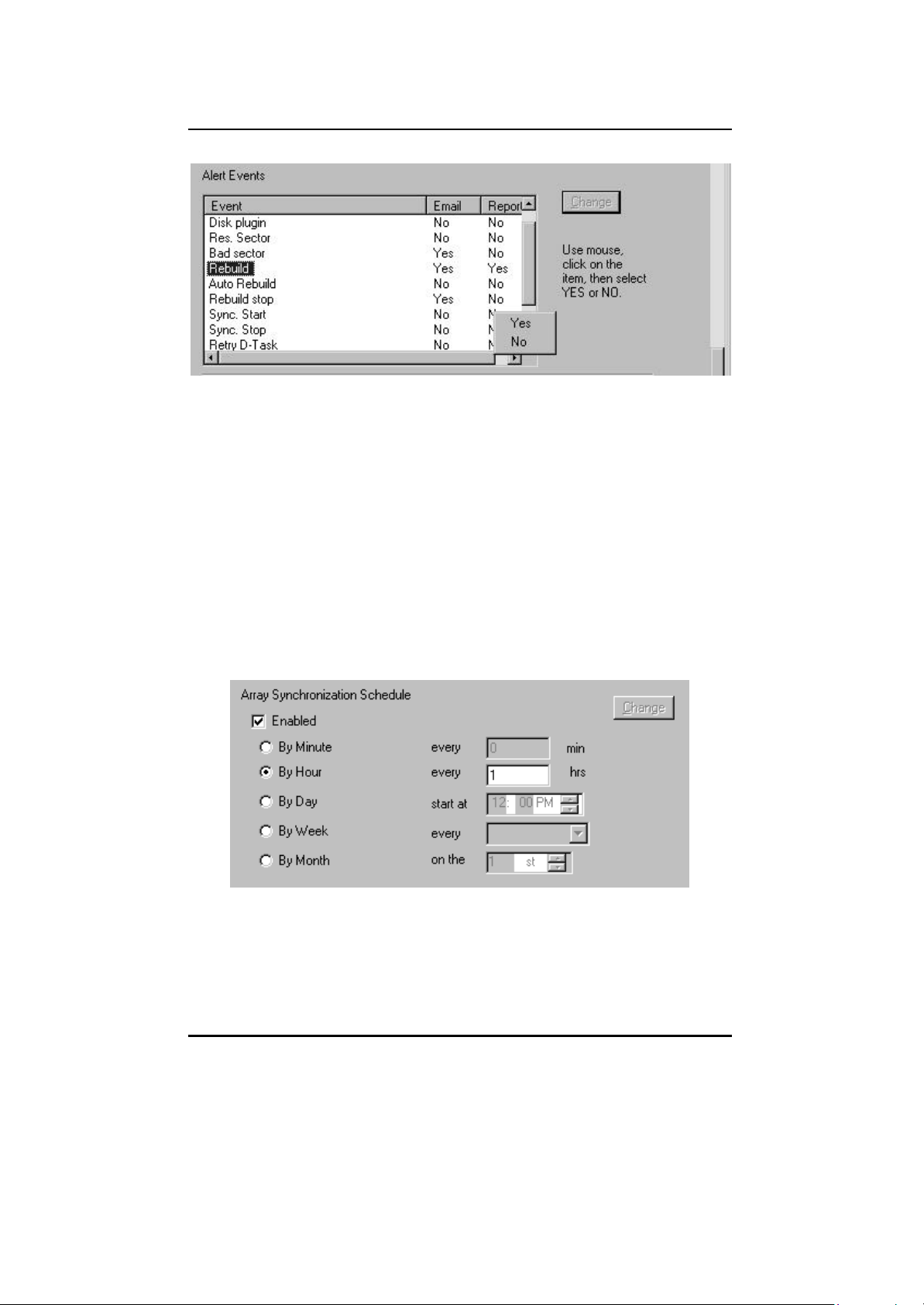
SuperTrak66™ User's Manual Chapter 5
Figure 49: Adding/Removing Events for Email Alert
2) Select the event you wish to modify in the “Event” column.
3) Right-click on the “Email” column and select “yes” to have this event send
alert email notification. Otherwise, select “no” to remove it as an alert event.
4) When you are finished making changes, click the “Change” button next to the
event selection scrollbox to update the SuperCheck configuration for email alert
notification.
NOTE: The "Report" column is used for event reporting to the utility. Events may
be accessed by right-clicking the IPOx item.
Scheduling Array Synchronization
The Schedule Array Synchronization section (see below) allows the administrator
to perform synchronization on a regularly-scheduled basis (by minute, by hour, by
day, by week, or by month).
Figure 50 : Scheduling Array Synchronization
1) To schedule synchronization, check the Enable box,
2) Select the scheduling options appropriate to your timetable
3) Click the "Change" button for the new schedule to take place.
- 70 -
Page 82

SuperTrak66™ User's Manual Chapter 5
NOTE: During Array Synchronization, users may continue to access the working
array and perform normal PC functions. However, system performance will be
slightly degraded and the process will take longer. Scheduling allows
synchronization to take place at off-peak time periods.
Viewing Message Agent Object icons
Double -clicking on a “Message Agent” icon will generate “I2O_RAID” and “User”
icons in the Object View. Left-clicking the I2O icon (left) will reveal specific Agent
information in the Information View (see next section). Left-clicking User icon(s) will
reveal User information.
Figure 51 : Message Agent Console icons
Message Agent Information View
The Message Agent Information View (see Figure 52 below) is a very long screen
and requires the use of the scroll bar to view all contained fields. Descriptions of
the sections within the Message Agent Information View are as follows:
NOTE: To see all the fields in the Information View pane, minimize the Console
View by placing the mouse cursor between the two panes so that the cursor
changes to the window control cursor, hold down the left mouse button, and drag
the boundary up until it disappears.
- 71 -
Page 83

SuperTrak66™ User's Manual Chapter 5
Figure 52 : Message Agent Information View
DNS Name, IP Address & Version Info
These three fields correspond to the “Server name,” “IP address,” and
“Version information” fields in the Message server information box above.
They cannot be modified from here.
Save User Password
By checking this option, your password will be saved. The next time you
use this console, you will not have to input your password again.
Email Alert on Error
By checking this option, notification through email can be implemented
when an error occurs on the currently highlighted SuperTrak66 Message
Agent. You will then need to enter the email address information of the
- 72 -
Page 84

SuperTrak66™ User's Manual Chapter 5
SuperTrak66 server in question in the two boxes directly below (“SMTP
server” and “Email ID”.)
SMTP Server
Enter the SMTP server name or IP address of your mail server. Contact the
System Administrator if you need this information. If you need to change
information already entered, press the “Change” button next to the text
box after typing in any new information.
Email ID
Enter the email ID of the email location for the specific machine housing
SuperTrak66 in this field. Email alerts will originate from this address. If
you need to change information already entered, press the “Change”
button next to the box after typing in any new information.
Alert Reci pients Email Address List
Enter the email addresses of all individuals that need notification when an
error occurs in a particular SuperTrak66 station in this field. If you are
monitoring multiple SuperTrak66 station, you must create a separate email
list for each SuperTrak66 station. After entering an email address, press
the “Add” button to confirm the entry.
Current Recipients List
This area of the Information View contains all email addresses to which an
alert will be sent in the event of an error occurring on the SuperTrak
system. To add a new address, enter it in the box; to remove an address,
highlight it and then press the “Remove” button.
- 73 -
Page 85

SuperTrak66™ User's Manual Chapter 5
Figure 53: Alert Events & Schedule Synchronization screen
Alert Events
This area (see above) allows you to choose which types of events will
generate an email alert and/or report. To do this, highlight a particular event
in the “Event” column, then click once in the same row on either the
“Email” or “Report” columns to toggle their active states between “Yes”
and “No”. The email notification sends email to the alert recipients. The
"Report" column affects which events are stored in the Event List on the
Message Agent. The Event list may be retrieved by right -clicking the IOPx
item. It may also be deleted from here.
Schedule Array Synchronization
Array synchronization is a periodic maintenance procedure for mirroring
(RAID 1, 0+1, 3, and 5) arrays to maintain data consistency on all mirrored
drives. In operation, array synchronization compares data on the mirrored
drives for any differences. If there are differences detected, data from the
primary drive(s) is automatically copied to the secondary drive(s). This
assures that all mirrored drives will contain the exact information.
- 74 -
Page 86

SuperTrak66™ User's Manual Chapter 5
5.6 User Management Functions
The “Users” icon in the Tree View is a folder containing a list of users
and administrators who are permitted access to a particular SuperTrak66
system’s status.
Creating A New User
1) Right-click the “Users” icon in the Tree View area of SuperCheck Main Menu.
Then left-click on “New” and select “User” from the pop-up selection.
Figure 54: Creating New User pull- down
2) A “New User ” icon will appear. Double -click on it to view the user Information
View.
3) Modify all the user information according to the desired access level for the
new user.
4) If the user has any level of administrative control, and the server is connected
to a WAN, make sure to set a password.
5) Click the “Commit ” button to update the user information.
Deleting an Existing User
1) Select the User icon in the Object View or Tree View representing the
particular user you wish to delete.
- 75 -
Page 87

SuperTrak66™ User's Manual Chapter 5
Figure 55 : Deleting User menu
2) Right-click the icon and select “Delete” from the pop-up menu.
3) Choose “Yes” if this is a user you wish to delete.
NOTE: SuperCheck will not allow deletion of the last account with admin privileges.
This protects the admin from being locked out of the system and having to reinstall SuperCheck.
Changing Passwords
1) Double- click the Admin/User icon in Tree View or Object View of the person for
which you want to change passwords.
2) In the Information View (see), type the new password in the labeled box and
confirm the password in the box below it.
3) Click “Commit” to enable the change or continue with other selections.
Assigning User Rights
1) Double- click the Admin/User icon in Tree View or Object View of the person for
which you want to assign Array Rights.
2) In the Information View (see figure 5-23), you may select from the following
rights: "Create Array," "Delete Array," "Maintain Array," "Array Statistics,"
"Adapter Maintenance," and "User Account." Click the appropriate boxes to
enable/disable these rights. See section 5.6.5 for a more detailed explanation
of these rights.
3) Click “Commit” to enable the change.
Viewing User/Admin Object icons
Double -clicking on the “Users” icon will generate “User” and “Admin” icons in the
Object View (see figure below). Clicking on the individual "User" and "Admin" icons
will reveal their access rights (see page 77).
- 76 -
Page 88

SuperTrak66™ User's Manual Chapter 5
Figure 56: User icons in Object View
The “Admin” icon in the Tree View represents the configuration of a user
who has “User Account Rights” on a particular SuperTrak66 system.
Double-clicking on the icon will display an “Administrator Information
View”, as shown in Figure 57 next page.
NOTE: No Object View will appear since this is the lowest level in this portion of
the Tree View.
User Information View
The User Information View screen (see Figure 57) offers the admin/user the ability
to assign passwords, array maintenance, adapter maintenance, and user account
rights. What follows is a description of the fields in the Information View.
User Name
This text box contains the name of the administrator / user.
Password
The “Password” text box contains the (mask hidden) password of the
administrator / user.
Confirm Password
The “Confirm password” text box is used when changing the password.
After entering the new password in the “Password” text box, enter it again
in the “Confirm password ” text box to ensure accuracy.
Array Administration Rights
By checking the boxes, the user will be able to create, delete, and
maintain arrays, and view array statistics.
NOTE: Array maintenance, creation, and deletion must be performed
locally on the actual machine where the SuperTrak66 card is physically
located. Such functions are greyed out on a remote monitoring station.
- 77 -
Page 89
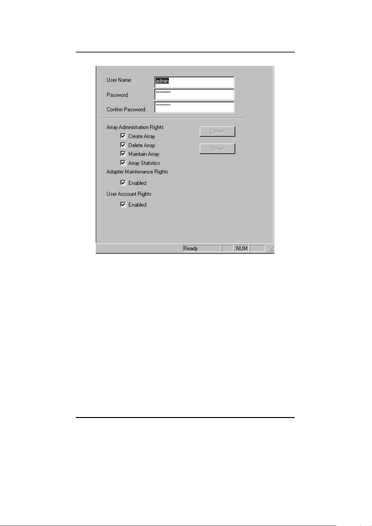
SuperTrak66™ User's Manual Chapter 5
Figure 57 : User Information View
Adapter Maintenance Rights
By checking the “Enabled” box, the user will be able to modify cache and
performance tuning parameters for the SuperTrak66 card.
User Account Rights
By checking the “Enabled” box, the user will be able to assign or modify
user “rights” (such as “Array Administration” or “Adapter Maintenance”
rights) of the users listed. This user will also be able to add or remove
other users.
Commit / Reset
If, as an administrator / user, you need to change your password, change
it as described above. If a mistake is made, press the “Reset” button to
revert to previously saved values. After correctly typing the new password
text, press the “Commit” button. The new password will then be
operational.
- 78 -
Page 90

SuperTrak66™ User's Manual Chapter 5
5.7 I2O RAID Functions
The “I2O RAID” icon(s) in the Tree View represents the I2O component
installed on a Message Agent. Through here, you can identify model
information and hardware/firmware versions.
Viewing I2O RAID Object icons
D ouble-clicking on an “I2O RAID” icon generates the “IOPx” icon in the Object
View (see below).
Figure 58 : I2O RAID Object View
Information View
In the Information View (see below), two fields are displayed: “Type” and “Version
information” which reflect the model number, name of the controller installed in the
system, and version information concerning the hardware and firmware. No fields
may be modified here.
Figure 59: I2O RAID Information View
- 79 -
Page 91
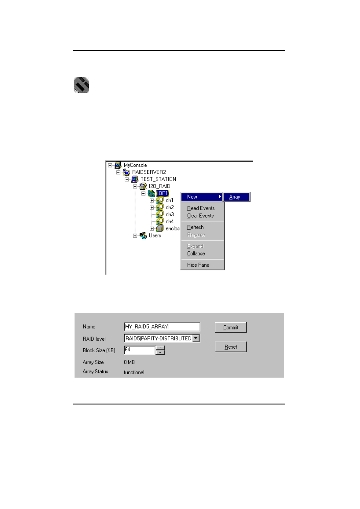
SuperTrak66™ User's Manual Chapter 5
5.8 IOPx Functions
The “IOPx” (I/O Platform #x) icon(s) represent individual SuperTrak66
controller cards which may be installed as part of a single or multiple
SuperTrak66 server system as seen by SuperCheck. From here, users may
create a new array, can view information on specific servers and SuperTrak66 cards.
In addition, the user may choose to alter how often and what conditions of all
SuperTrak66 cards' onboard memory will flush their data during operation
Creating a New Array
1) Select the IOPx icon in the Tree View where you want to create an array.
2) Right-click the icon. Click “New”, then select “Array” from the pop-up menu
as show in figure below.
Figure 60: Creating New Array pull-down
2) Enter the pertinent information in the “Name,” RAID Level” and “Block Size”
fields (see figure below)
Figure 61: Labeling New Array window
- 80 -
Page 92

SuperTrak66™ User's Manual Chapter 5
4) The new array icon will be created in the Tree View, titled with the text entered
into the “Name” field.
5) Drag and drop any unassigned drive icon within the Tree View area on top of
the array icon which you have just created in order to add the drive to the array
(unassigned drive icons do not have a red arrow in the upper left corner). Hard
drive(s) will then be assigned to the array in the order that they are dragged on
to the array icon.
6) If you have incorrectly selected a disk for this array, highlight that disk in Tree
View, righ t-click mouse, and select Delete. The disk will be removed from this
array.
7) Repeat step 5 until the array is completed.
8) Press the “Commit” button and reboot the Operating System to establish the
new array.
Reading/Clearing Events from SuperTrak Memory Buff er
SuperCheck allows the user to read alarm/maintenance events maintained by
SuperTrak66's onboard memory log, print a listing of these events, save the log to a
file, or clear all events from memory. Clearing events should be performed on a
periodic basis in order to reduce the length and size of the event buffer log.
1) To read events from the log, make sure the IOPx icon of the correct
SuperTrak66 controller card in Tree View is highlighted.
2) Left-click "Read Events" or "Clear Event" or use pull-down menu at top.
3) Clicking "Read Events" will enable the Event Viewer screen (see figure below)
Figure 62: Read/Clear Events pull- down
- 81 -
Page 93
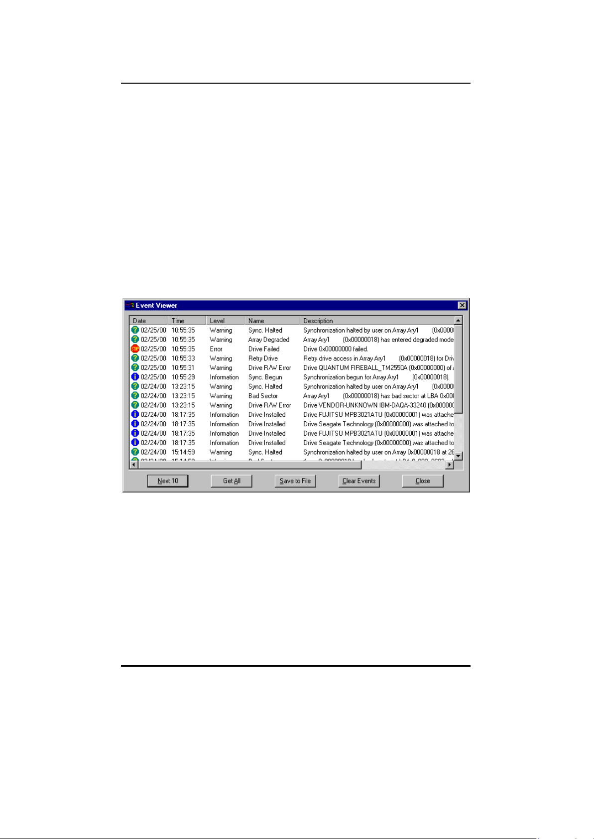
SuperTrak66™ User's Manual Chapter 5
Using The Event Viewer
After "Read Events" has been selected, the Event Viewer window appears (see
below). The Event Viewer lists events according to type, date, status, and array
status. The entire events log is not shown or accessed from the memory buffer
since it can be quite large.
1) To sort the list according to category, click on the heading names
2) To navigate through the events listing, use the "Next 10" buttons to go forward
through events.
3) To capture all events contained in the buffer prior to printing, click on the “Get
All” button.
4) To save the Events log to a file, click the “Save As” button. Input a filename
and click “Close” button.
5) Press "Finish" button to close the Event Viewer and return to the SuperCheck
Main Menu.
Figure 63 : Events Viewer screen
Changing Flush Memory Timing
As part of the System Cache Policy settings, a user is able to change the amount
of time the SuperTrak66 card holds cached data in its onboard memory.
1) Double- click the IOPx icon in Tree View.
2) In the Information View (see Figure 65 on p. 84), enter a new number to change
the maximum number of seconds in which data in SuperTrak66's cache
memory is held before being cleared.
3) Click “Commit” to enable the change or continue with other selections.
- 82 -
Page 94

SuperTrak66™ User's Manual Chapter 5
Changing Dirty Threshold Flush Start Setting
As part of the System Cache Policy settings, a user is able to change the
maximum percentage of the total onboard SuperTrak66 memory that can be
occupied by data that has not yet been written to disk (i.e. "dirty" data) before it is
flushed from memory.
1) Double- click the IOPx icon in Tree View.
2) In the Information View (see Figure 65 on p. 84), enter a new number to change
the maximum percentage of cache memory that can be occupied by "dirty"
data before being cleared automatically.
3) Click “Commit” to enable the change or continue with other selections.
Changing Dirty Threshold Flush Stop Setting
As part of the System Cache Policy settings, a user is able to set the minimum
percentage of memory allowed by SuperTrak66 for data that has not yet been
written to disk (i.e. "dirty" data). This will stop SuperTrak66 from cleansing "dirty"
data from memory beyond this percentage point.
1) Double- click the IOPx icon in Tree View.
2) In the Information View (see Figure 65 on p. 84), enter a new number to change
the minimum percentage level of cache memory that can be occupied by
"dirty" data and stop flushing automatically.
3) Click “Commit” to enable the change or continue with other selections.
Viewing IOPx Object icons
Double -clicking on this icon generates the components connected to the controller
card – (from left) hard drive channels (first, second, and third icons below),
enclosure components (fifth icon below), and arrays (sixth icon below) in Object
View. Clicking on these icons will generate different information screens. See
section 5.10 for drive channels, section 5.11 for enclosures, and section 5.12 for
array.
Figure 64 : IOPx Object View icons
- 83 -
Page 95

SuperTrak66™ User's Manual Chapter 5
IOPx Information View
The Information View displays the “IOPx Information View” as seen in Figure 65.
The fi elds displayed in the “IOPx Information View” are defined as follows:
System Information
The “System information” section contains a list box which holds
information concerning the controller’s name, version number, timestamps,
and size of file. Below it are three text fields: “Processor,” “Memory size”
and “Hardware”. They show the type of CPU running on the controller, the
amount of EDO memory present on the controller, and the type of inter face
chip on the controller respectively. Fields may not be modified.
Figure 65 : IOPx Information View
- 84 -
Page 96

SuperTrak66™ User's Manual Chapter 5
System Cache Policy
The “System cache policy” section contains a series of fields and text
boxes as follows:
Cache block size (KB)
This field reflects the size of a unit block in the cache module. It
cannot be modified from here.
Total cache size (MB)
This field indicates how much of the SuperTrak66 EDO memory is
being used for R/W caching plus RAID XOR data space.
NOTE : Not all installed memory is available. A portion of cache
memory is used to house I2O and other components of the
Promise driver.
RW cache size (MB)
This field indicates how much of the SuperTrak66 EDO memory is
being used for R/W caching only.
Flush frequency timer (sec)
This field shows how long (in seconds) a block of “dirty” data can
remain in memory without being flushed. This field affects the
cache configurations of any array attached to this IOP.
Dirty threshold flush start
This field indicates the flush start threshold percentage of dirty
blocks. When the percentage of dirty blocks residing in memory
exceeds the threshold, flushing will begin automatically. This field
affects the cache configurations of any array attached to this IOP.
Dirty threshold flush stop
This field shows the flush stop threshold percentage of dirty blocks.
When the percentage of dirty blocks residing in memory falls
below the threshold, flushing will stop automatically. This field
affe cts the cache configurations of any array attached to this IOP.
Commit / Reset
If changes are made to any of the “System Cache Policy” fields,
press the “Commit” button to save the new settings, or “Reset”
to make the values revert to their saved settings.
NOTE: The new settings will NOT be enabled until the next
system boot.
- 85 -
Page 97

SuperTrak66™ User's Manual Chapter 5
5.9 Channel (chx) Functions
The “chx” icons represent particular drive channels (i.e. 1,2,3,4) on the
SuperTrak66 controller card.
Viewing Channel Object icons
Double -clicking on the icon displays the icons of the hard drives connected to the
channel in the Object View. There is no Information View for Channel (chx). Double-
click on the drive icons in the Object View to obtain a drive’s Information View (see
p. 87).
Assigned drive icon indicates drive that is already part of an existing
SuperTrak66 array.
Unassigned drive icon indicates drive is not a part of an existing
SuperTrak66 array. User may choose to leave drive to be used as a "hot"
spare for a RAID 1, 3, or 5 level array. Unassigned drives may be assigned
to create new arrays.
Figure 66 : Channelx's Object View
- 86 -
Page 98

SuperTrak66™ User's Manual Chapter 5
5.10 Hard Drive Function s
The hard drive icons represent hard drives connected to the SuperTrak66
controller card. The icons will be identified by the drive’s make, model,
status, size, DMA mode, and array configuration.
Hard Drive Information View
Since the hard drives are the last level in the SuperCheck Tree View, the Object
View will not contain any information. Double-clicking on a hard drive icon updates
the Information View with information regarding the particular drive, as depicted
below.
Figure 67: Hard drive Information View
This Information View simply displays information about the drive. None of the fields
may be modified. The field descriptions are as follows:
Disk Model Name
This field shows the make and model of the disk.
Disk Status
This field shows the disk’s operational status.
Disk Size
This field reflects the disk’s total physical capacity.
Mode Setting
This field identifies what transfer mode the disk is set for read/writes
Configuration
This field shows whether the drive is free (“hot spare”) or is assigned to an
array.
- 87 -
Page 99
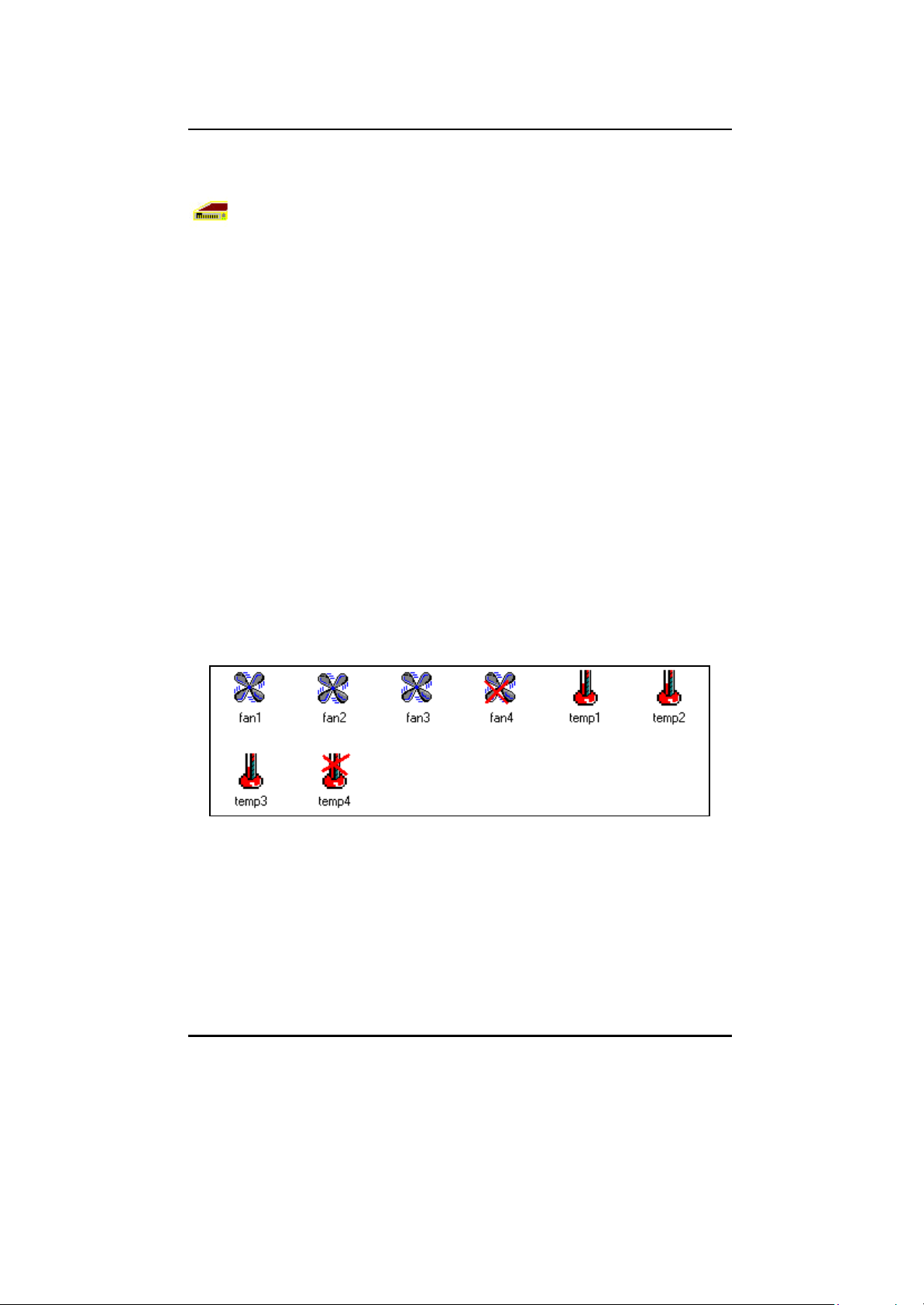
SuperTrak66™ User's Manual Chapter 5
5.11 Enclosure Functions
The “Enclosure X” icon(s) represent the server-level monitoring capabilities
of SuperCheck. From this icon, users may choose to enable alerting alarms
during rebuilding and synchronizing of arrays. In addition, they may monitor
enclosure status if the user has mounted the hard drives inside optional
FastSwap66 or SuperSwap66 “hot” swap boxes (one drive per box) manufactured
by Promise. FastSwap66 permits monitoring fan and housing temperature status.
SuperSwap66 allows monitoring fan, temperature, and power.
Enabling Rebuild/Synchronization Beeper
System administrators may wish to enable or disable an audible beeper alert that
the SuperTrak66 emits during rebuild of drives and synchronization of drives. The
beeper warns the admin that the system is in a degraded status during these
processes and alerts admin when the process is complete.
1) Double- click the Enclosure icon in Tree View.
2) In the Information View (see Figure 69), check or uncheck the
Rebuild/synchronization Beeper box.
Viewing Enclosure Object icons
Double -clicking on the “Enclosure” icon in Tree View will display “fan” and
“temp” icons in the Object View associated with that enclosure. Clicking on any of
the Object View icons will display an Information View nearly identical to the
“Enclosure” Information View. The only difference is that the Object View will not
appear.
Figure 68 : Enclosure Object View
- 88 -
Page 100

SuperTrak66™ User's Manual Chapter 5
Enclosure Information View
The Information View shows a graphical representation of the FastSwap66 or
SuperSwap66 “hot” swap enclosures, along with the monitored components (fan,
temperature, or power), as shown below.
Figure 69: Enclosure Information View
The “fan” icons will display either a “working” fan, or a failed (“error”) fan. The
temperature icon will display a “working” thermometer (with the internal
temperature in °F, or an “error” thermometer (if the temperature inside the
enclosure exceeds 122° F). The “power” icons (not shown here) will display eithe r
“on” or “off” when using the SuperSwap66 enclosure.
- 89 -
 Loading...