

Page 1
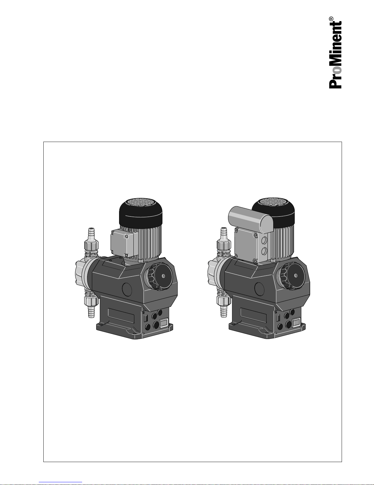
Metering pumps
Vario C, VAMC
Operating instructions
EN
Original operating instructions (2006/42/EC)Part no. 987096 BA VA 022 08/18 EN
Please carefully read these operating instructions before use. · Do not discard.
The operator shall be liable for any damage caused by installation or operating errors.
The latest version of the operating instructions are available on our homepage.
Page 2

Read the following supplementary information in its entirety! Should you
already know this information, you will benefit more from referring to the
operating instructions.
The following are highlighted separately in the document:
n Enumerated lists
Operating guidelines
ð
Outcome of the operating guidelines
- see (reference)
Information
This provides important information relating to the cor‐
rect operation of the unit or is intended to make your
work easier.
Safety notes
Safety notes are identified by pictograms - see Safety Chapter.
These operating instructions conform to current EU regulations applicable
at the time of publication.
Please state identity code and serial number, which you can find on the
nameplate when you contact us or order spare parts. This enables the
device type and material versions to be clearly identified.
Supplementary information
Fig. 1: Please read!
Validity
State the identity code and serial number
Supplemental directives
2
Page 3

Table of contents
1
Identity code.................................................................................... 4
2 Safety Chapter................................................................................. 5
3 Carrying out repairs......................................................................... 9
4 Information on disposal................................................................. 12
5 Technical Data............................................................................... 13
5.1 Performance data.................................................................. 13
5.2 Precision............................................................................... 13
5.3 Shipping weight..................................................................... 13
5.4 Wetted materials................................................................... 14
5.5 Ambient conditions................................................................ 14
5.5.1 Ambient temperatures........................................................ 14
5.5.2 Media temperatures........................................................... 14
5.5.3 Air humidity........................................................................ 14
5.6 Motor data............................................................................. 14
5.7 Stroke sensor "Sigma".......................................................... 15
5.8 Sound pressure level............................................................ 15
5.9 Supplementary information for modified versions................. 15
6 Dimensional Drawings................................................................... 16
7
Diagrams for Setting the Capacity................................................. 17
8 Wear parts Vario C, VAMC............................................................ 18
8.1 Spare parts kits..................................................................... 18
8.2 Diaphragms........................................................................... 18
9 Declaration of Conformity for Machinery....................................... 19
Table of contents
3
Page 4
1 Identity code
Product range Vario, Version c
VAMC Capacity
_ _ _ _ _ Performance data at maximum back pressure and type: refer to nameplate on the pump housing
Material of dosing head/valves
PPE Polypropylene with EPDM seal
PCB PVC with EPDM seal
PVT PVDF with PTFE seal
SST Stainless steel with PTFE seal
Dosing head design
0 no valve spring (standard)
1 with 2 valve springs, Hastelloy C4
Hydraulic connector
0 Standard connection - Union nut with hose connection
1 Union nut and PVC insert
2 Union nut and PP insert
3 Union nut and PVDF insert
4 Union nut and stainless steel insert
5 Union nut and PVC tube nozzle
6 Union nut and PP tube nozzle
7 Union nut and PVDF tube nozzle
8 Union nut and stainless steel tube nozzle
Design
0
with ProMinent® logo (standard)
M Modified
Motor connector
_ refer to nameplate on motor
Stroke sensor
0 No stroke sensor
3 with stroke sensor (Namur)
Setting the stroke length
0 Manual (standard)
Identity code
4
Page 5

2 Safety Chapter
WARNING!
We should like to remind the operator of the pump that
he has a duty to use the advice on safety and operation
of the pump for operating instructions for his staff.
The following signal words are used in these operating instructions to
denote different severities of danger:
Signal word Meaning
WARNING Denotes a possibly dangerous sit‐
uation. If this is disregarded, you
are in a life-threatening situation
and this can result in serious inju‐
ries.
CAUTION Denotes a possibly dangerous sit‐
uation. If this is disregarded, it
could result in slight or minor inju‐
ries or material damage.
The following warning signs are used in these operating instructions to
denote different types of danger:
Warning signs Type of danger
Warning – high-voltage.
Warning – danger zone.
n Only use the pump to meter liquid feed chemicals.
n Only use the pump after it has been correctly installed and started up
in accordance with the technical data and specifications contained in
the operating instructions.
n Observe the general limitations with regard to viscosity limits, chem‐
ical resistance and density - see also ProMinent® resistance list (In the
product equipment catalogue or at
www.prominent.com
!
n All other uses or modifications are prohibited.
n The pump is not intended for the metering of gaseous media and
solids.
n The pump is not intended to meter extremely hazardous media or
media harmful to life.
n The pump is not intended to meter flammable media.
n The pump is not intended to meter oxidants without the use of suitable
protective equipment.
n The pump is not intended for the metering of explosive media.
n The pump is not intended for operation in areas at risk from explosion.
n The pump is not intended for unprotected outside use.
n The pump is only intended for industrial use.
n The pump should only be operated by trained and authorised per‐
sonnel.
n You have a responsibility to adhere to the information contained in the
operating instructions at the different phases of the unit's service life.
General
Identification of safety notes
Warning signs denoting different types of
danger
Intended use
Safety Chapter
5
Page 6

Action Qualification
Storage, transport, unpacking Instructed person
Assembly Technical personnel, service
Planning hydraulic installation Qualified personnel who have a
thorough knowledge of metering
pumps.
Hydraulic installation Technical personnel, service
Installation, electrical Electrical technician
Operation Instructed person
Maintenance, repair Technical personnel, service
Decommissioning, disposal Technical personnel, service
Troubleshooting Technical personnel, electrical
technician, instructed person,
service
Explanation of the terms:
Technical personnel
A qualified employee is deemed to be a person who is able to assess the
tasks assigned to him and recognise possible dangers based on his/her
technical training, knowledge and experience, as well as knowledge of
pertinent regulations.
Note:
A qualification of equal validity to a technical qualification can also be
gained by several years employment in the relevant work area.
Electrical technician
Electrical technicians are deemed to be people, who are able to complete
work on electrical systems and recognise and avoid possible dangers
independently based on their technical training and experience, as well as
knowledge of pertinent standards and regulations.
Electrical technicians should be specifically trained for the working envi‐
ronment in which they are employed and know the relevant standards and
regulations.
Electrical technicians must comply with the provisions of the applicable
statutory directives on accident prevention.
Instructed person
An instructed person is deemed to be a person who has been instructed
and, if required, trained in the tasks assigned to him/her and possible dan‐
gers that could result from improper behaviour, as well as having been
instructed in the required protective equipment and protective measures.
Service
Customer Service department refers to service technicians, who have
received proven training and have been authorised by ProMinent or Pro‐
Maqua to work on the system.
Qualification of personnel
Safety Chapter
6
Page 7

WARNING!
Warning of hazardous feed chemical
Should a dangerous feed chemical be used: it may
escape from the hydraulic components when working on
the pump, material failure or incorrect handling of the
pump.
– Take appropriate protective measures before
working on the pump (e.g. safety glasses, safety
gloves, ...). Adhere to the material safety data sheet
for the feed chemical.
–
Drain and flush the liquid end before working on the
pump.
WARNING!
Danger from hazardous substances!
Possible consequence: Fatal or very serious injuries.
Please ensure when handling hazardous substances
that you have read the latest safety data sheets provided
by the manufacture of the hazardous substance. The
actions required are described in the safety data sheet.
Check the safety data sheet regularly and replace, if
necessary, as the hazard potential of a substance can
be re-evaluated at any time based on new findings.
The system operator is responsible for ensuring that
these safety data sheets are available and that they are
kept up to date, as well as for producing an associated
hazard assessment for the workstations affected.
WARNING!
Danger of electric shock
A mains voltage may exist inside the pump housing.
– If the pump housing has been damaged, you must
disconnect it from the mains immediately. It may
only be returned to service after an authorised
repair.
CAUTION!
Warning of feed chemical spraying around
Feed chemical can spray out of the hydraulic compo‐
nents if they are manipulated or opened due to pressure
in the liquid end and adjacent parts of the system.
– Disconnect the pump from the mains power supply
and ensure that it cannot be switched on again by
unauthorised persons.
–
Depressurise the system before commencing any
work on hydraulic parts.
CAUTION!
Warning of feed chemical spraying around
An unsuitable feed chemical can damage the parts of
the pump that come into contact with the chemical.
– Take into account the resistance of the wetted mate‐
rials and the ProMinent Resistance List when
selecting the feed chemical - see the ProMinent
Product Catalogue or visit ProMinent.
Safety information
Safety Chapter
7
Page 8

CAUTION!
Danger of personnel injury and material damage
The use of untested third party parts can result in per‐
sonnel injuries and material damage.
– Only fit parts to metering pumps, which have been
tested and recommended by ProMinent.
CAUTION!
Danger from incorrectly operated or inadequately main‐
tained pumps
Danger can arise from a poorly accessible pump due to
incorrect operation and poor maintenance.
– Ensure that the pump is accessible at all times.
– Adhere to the maintenance intervals.
All isolating protective equipment must be installed for operation:
n Drive front cover
n Motor fan cowling
n Motor terminal box cover
n Plug (Pos. 9 in Fig. 6 in Chap. "Repair")
In the event of an electrical accident, disconnect the mains cable from the
mains or press the emergency cut-off switch fitted on the side of the
system!
If feed chemical escapes, also depressurise the hydraulic system around
the pump as necessary. Adhere to the safety data sheet for the feed
chemical.
Sound pressure level LpA < 70 dB according to EN ISO 20361
at maximum stroke length, maximum stroke rate, maximum back pressure
(water)
Isolating protective equipment
Information in the event of an emergency
Sound pressure level
Safety Chapter
8
Page 9

3 Carrying out repairs
WARNING!
Only return the metering pump for repair in a cleaned
state and with a flushed liquid end - refer to the chapter
"Decommissioning"!
Only return metering pumps with a completed Decon‐
tamination Declaration form. The Decontamination Dec‐
laration constitutes an integral part of an inspection /
repair order. A unit can only be inspected or repaired
when a Declaration of Decontamination Form is sub‐
mitted that has been completed correctly and in full by
an authorised and qualified person on behalf of the
pump operator.
The "Decontamination Declaration Form" can be found
at www.prominent.de.
WARNING!
Warning of hazardous feed chemical
Should a dangerous feed chemical be used: it may
escape from the hydraulic components when working on
the pump, material failure or incorrect handling of the
pump.
– Take appropriate protective measures before
working on the pump (e.g. safety glasses, safety
gloves, ...). Adhere to the material safety data sheet
for the feed chemical.
– Drain and flush the liquid end before working on the
pump.
CAUTION!
Warning of feed chemical spraying around
Feed chemical can spray out of the hydraulic compo‐
nents if they are manipulated or opened due to pressure
in the liquid end and adjacent parts of the system.
– Disconnect the pump from the mains power supply
and ensure that it cannot be switched on again by
unauthorised persons.
–
Depressurise the system before commencing any
work on hydraulic parts.
CAUTION!
Warning of feed chemical spraying around
An unsuitable feed chemical can damage the parts of
the pump that come into contact with the chemical.
– Take into account the resistance of the wetted mate‐
rials and the ProMinent Resistance List when
selecting the feed chemical - see the ProMinent
Product Catalogue or visit ProMinent.
Safety information
Carrying out repairs
9
Page 10

CAUTION!
Warning of feed chemical spraying around
PTFE seals, which have already been used / com‐
pressed, can no longer reliably seal a hydraulic connec‐
tion.
– New, unused PTFE seals must always be used.
CAUTION!
Danger of personnel injury and material damage
The use of untested third party parts can result in per‐
sonnel injuries and material damage.
– Only fit parts to metering pumps, which have been
tested and recommended by ProMinent.
P_VA_0005_SW
1
2
3
9
4
6
5
Fig. 2: Liquid end parts
1 Suction connector
2 Dosing head
3 Pressure connector
4 Diaphragm
5 Backplate
6 Slide rod
9 Plug
n If necessary take protective measures.
n Adhere to the material safety data sheet for the feed chemical.
n Ensure that the system is at atmospheric pressure.
1. Empty the liquid end (turn the liquid end upside down and allow the
feed chemical to run out; flush out with a suitable medium; flush the
liquid end thoroughly when using hazardous feed chemicals!)
2. Turn the stroke adjustment dial as far as 0% stroke length when the
pump is running (the drive axle is then difficult to turn).
3. Switch off the pump and secure it to prevent it being switched on
again.
4. Unscrew the hydraulic connectors on the discharge and suction
side.
5. Remove the screws.
Carrying out repairs
10
Page 11

6. Loosen the dosing head (2) and the backplate (5) from the pump
housing - but only loosen!
7. Hold the pump housing with one hand and clamp the diaphragm (4)
with the other hand between the dosing head (2) and the backplate
(5).
8. Loosen the diaphragm (4) from the drive axle with a gentle back‐
wards turn of the dosing head (2), diaphragm (4) and backplate (5)
in an anticlockwise direction. (Possibly hold the slide rod (6) using
an appropriate wrench through the opening for the plug (9).)
9. Unscrew the diaphragm (4) completely from the drive axle.
10. Clean the sealing surfaces.
11. Place the diaphragm (4) into the backplate (4).
12. Position the dosing head (2) so that the suction connector (1) lies
above the leakage hole of the backplate (5).
13. Insert the screws and manually tighten the diaphragm in a clockwise
direction up to the slide rod (6).
14. Switch the pump on.
15. Set the stroke length to 100%.
16. Place the dosing head (2) with the screws onto the diaphragm (4)
and the backplate (5) - the suction connector must be pointing
downwards in the pump's subsequent fitting position.
17. When the pump is running, rotate the liquid end as far to the right
until the suction connection (1) is pointing vertically downwards.
18. Now disconnect the pump from the power supply so that the slide
rod (6) comes to a standstill approximately at the rear end position.
19. Gently tighten the screws (1) and then tighten them diagonally. See
below for the tightening torque.
20. With PP types with bleed valve: Allow the cover of the liquid end to
rest in the dosing head, then press the grip on the bleed valve into
the dosing head.
CAUTION!
Leakage possible
– Check the tightening torque of the screws
after 24 hours of operation!
–
With PP dosing heads, recheck the tightening
torque again after three months!
Data Value Unit
Tightening torque for screws: 4.5 ... 5.0 Nm
Tightening torque
Carrying out repairs
11
Page 12

4 Information on disposal
In accordance with the European Directive 2012/19/EU on waste electrical
and electronic equipment, this device features the symbol showing a
waste bin with a line through it. The device must not be disposed of along
with domestic waste. To return the device, use the return and collection
systems available and observe the local legal requirements.
Sign indicating EU collection system
Information on disposal
12
Page 13

5 Technical Data
WARNING!
Risk of personal injuries
Please observe the ”Supplement for modified version“ at
the end of the chapter!
It replaces and supplements the technical data!
5.1 Performance data
The capacity at maximum back pressure can be found on the nameplate
on the housing.
VAMC Type Suction lift Permissible priming pressure, suction
side
m WS bar
10008, 10016, 07026, 07042 7 2.8
07012, 07024, 04039, 04063 6 1.7
All figures refer to water at 20 °C.
The suction lift applies to filled suction line and filled liquid end - when
installed correctly.
5.2
Precision
Data Value Unit
Reproducibility ±2 % *
* - when installed correctly, under constant conditions, at least 30%
stroke length and water at 20 °C
5.3 Shipping weight
Material version Shipping weight
kg
PVT 6.0
SST 7.2
Only for "M - modified" design:
Precision
Technical Data
13
Page 14

5.4 Wetted materials
Material version Liquid end Suction/pressure
connector
Seals Balls Valve seat
PPE PP PP EPDM Glass PP
PCB PVC PVC FPM-B Glass PVC
PVT PVDF PVDF PTFE Ceramic PTFE
SST Stainless steel
1.4404
/1.4571
Stainless steel
1.4581/1.4571
PTFE Stainless steel
1.4404
PTFE
Diaphragm is PTFE coated.
5.5
Ambient conditions
5.5.1 Ambient temperatures
Data Value Unit
Storage and transport temperature -10 ... +50 °C
Ambient temperature in operation (drive +
motor):
-10 ... +45 °C
5.5.2 Media temperatures
Material version PPE PCB PVT SST
Long-term temperature*
[°C]
-10 ... +50 -10 ... +45 -10 ... +50 -10 ... +50
Max. temperature for 15
min** [°C]
100 60 100 120
* at max. operating pressure
** at max. 2 bar
5.5.3
Air humidity
Maximum air humidity*: 95% rel. humidity
*non-condensing
5.6
Motor data
The key electrical data for the motor can be found on the nameplate on
the motor.
Motor data sheets, special motors, special motor flanges
–
Further information on motors can be found on our
homepage under motor data sheet.
Pump, compl.
Air humidity
Electrical data
Technical Data
14
Page 15

5.7 Stroke sensor "Sigma"
Install the sensor according to the chapter "Installation,
electrical".
5–25 V DC, in accordance with Namur or DIN 60947-5-6, potential-free
design.
Data Value Unit
Nominal voltage * 8 VDC
Power consumption - active surface
uncovered
> 3 mA
Power consumption - active surface cov‐
ered
< 1 mA
Rated switching distance 1.5 mm
* Ri ~ 1 kΩ
Cable colour Polarity
blue -
brown +
5.8 Sound pressure level
Sound pressure level LpA < 70 dB according to EN ISO 20361
at maximum stroke length, maximum stroke rate, maximum back pressure
(water)
5.9
Supplementary information for modified versions
(With identity code specification "Version": "M" - "modified")
Technical data of pumps in the modified version can deviate from those of
the standard pumps. They can be queried by stating the details of the
serial number.
During operation with an automatic stroke length adjustment control
together with a variable speed motor, the stroke rate must not fall below
30 strokes / min. Otherwise technical problems occur, because the
mechanical resistance of the stroke adjustment spindle becomes too high.
The motor data sheets for the modified version are valid. They may
deviate from the standard motor data sheets.
With a modified version, it is absolutely necessary to specify the details of
the serial number requesting and ordering the spare and replacement
parts.
Namur sensor (identity code characteristic
"stroke sensor": 3)
Sound pressure level
Technical data
motor
Spare parts
Technical Data
15
Page 16

6 Dimensional Drawings
–
Compare the dimensions on the dimension sheet
and pump.
–
All dimensions are in mm.
61_01_101_00_53_72_05
P_VA_0003_SW
Fig. 3: Dimensional drawing of Vario C
Material ver‐
sion
A B C D E * F ** Connector
PCB 191 142 92 243 226 176 DN10
PPE 191 142 92 243 226 178 DN10
PVT 191 142 95 246 228 180 DN10
SST 190 140 90 241 226 180 DN10
* with hose nozzle
** with insert
Dimensional drawing of Vario C
Dimensional Drawings
16
Page 17

7 Diagrams for Setting the Capacity
Vario (FM 042)
0
5
0 20 40 60 80 100 120
S [%]
Q (l/h)
VAMc 07042
VAMc 07026
VAMc 10008
VAMc 10016
0
5
10
15
20
25
30
35
40
45
0 2 4 6 8 10 12
p [bar]
Q (l/h)
VAMc 07042
VAMc 07026
VAMc 10008
VAMc 10016
Vario (FM 063)
0
5
10
15
20
25
30
35
40
45
50
Q (l/h)
0 20 40 60 80 100 120
s (%)
55
60
65
VAMc 04063
VAMc 04039
VAMc 07012
VAMc 07024
0
5
10
15
20
25
30
35
40
45
50
Q [l/h]
0 2 4 6 8 10 12
s [bar]
55
60
65
VAMc 04063
VAMc 04039
VAMc 07012
VAMc 07024
Fig. 4: Capacity Q at minimum back pressure dependent on the stroke length s and capacity Q dependent on the back
pressure p.
Diagrams for Setting the Capacity
17
Page 18

8 Wear parts Vario C, VAMC
The spare parts kit generally includes the wear parts for the liquid ends.
8.1
Spare parts kits
Scope of delivery PPE, PCB, PVT:
1 diaphragm
1 suction valve, complete
1 discharge valve, complete
2 valve balls
1 sealing sets complete (cover rings, ball seat housings)
Scope of delivery SST:
1 diaphragm
2 valve balls
1 complete sealing set (cover rings, gaskets, ball seat)
Tab. 1: Types 10008, 10016, 07026, 07042
Liquid end Material version Order no.
FM 042 - DN 10 PPE 910753
FM 042 - DN 10 PCB 910754
FM 042 - DN 10 PVT 1003641
FM 042 - DN 10 SST 910751
Tab. 2: Types 07012, 07024, 04039, 04063
Liquid end Material version Order no.
FM 063 - DN 10 PPE 910758
FM 063 - DN 10 PCB 910759
FM 063 - DN 10 PVT 1003642
FM 063 - DN 10 SST 910756
8.2 Diaphragms
Tab. 3: Diaphragms for ...
Liquid end Order no.
FM 042, Types 10008, 10016, 07026, 07042 811458
FM 063, Types 07012, 07024, 04039, 04063 811459
Wear parts Vario C, VAMC
18
Page 19

9 Declaration of Conformity for Machinery
In accordance with DIRECTIVE 2006/42/EC OF THE EUROPEAN PAR‐
LIAMENT AND OF THE COUNCIL, Appendix I, BASIC HEALTH AND
SAFETY REQUIREMENTS, section 1.7.4.2. C.
We,
n ProMinent GmbH
n Im Schuhmachergewann 5 - 11
n DE - 69123 Heidelberg,
hereby declare that the product specified in the following, complies with
the relevant basic health and safety requirements of the EC Directive, on
the basis of its functional concept and design and in the version distributed
by us.
Any modification to the product not approved by us will invalidate this dec‐
laration.
Tab. 4: Extract from the Declaration of Conformity
Designation of the product: Metering pump, Vario C product range
Product type: VAMc...
Serial number: see nameplate on the device
Relevant EC directives: EC Machinery Directive (2006/42/EC)
Compliance with the protection targets of the Low Voltage Directive 2014/35/EU
according to Appendix I, No. 1.5.1 of the Machinery Directive 2006/42/EC
EC EMC Directive (2014/30/EU)
Harmonised standards applied, in
particular:
EN ISO 12100:2010
EN 809:1998 + A1:2009 + AC:2010
EN 6100-6-2:2005 + AC:2005
EN 6100-6-3:2007 + A1:2011 + AC:2012
Date: 20.04.2016
You will find the EC Declaration of Conformity to download on our home‐
page.
Declaration of Conformity for Machinery
19
Page 20

987096, 3, en_GB
© 2012
ProMinent GmbH
Im Schuhmachergewann 5-11
69123 Heidelberg
Germany
Telephone: ++49 6221 842-0
Fax: ++49 6221 842-419
Email: info@prominent.com
Internet: www.prominent.com
 Loading...