

ProMinent DULCO turb C Series, TUC 1, TUC 2, TUC 4, TUC 3 Assembly And Operating Instructions Manual
Page 1

Assembly and operating instructions
DULCO® turb C
Turbidity sensor
Please carefully read these operating instructions before use! · Do not discard!
The operator shall be liable for any damage caused by installation or operating errors!
Technical changes reserved.
Part no. 986062 BA DT 034 01/11 EN
Page 2

ProMinent Dosiertechnik Heidelberg GmbH
Im Schuhmachergewann 5 - 11
69123 Heidelberg
Telephone: +49 6221 842-0
Fax: +49 6221 842-419
email: info@prominent.de
Internet: www.prominent.com
986062, 1, en_GB
© 2011
2
Page 3

Supplemental instructions
General non-discriminatory approach
In order to make it easier to read, this
document uses the male form in
grammatical structures but with an
implied neutral sense. It is aimed
equally at both men and women. We
kindly ask female readers for their
understanding in this simplification of
the text.
Supplementary information
Read the following supplementary
information in its entirety!
The following are highlighted sepa‐
rately in the document:
n Enumerated lists
Instructions
Results of the instructions
ð
Information
Safety information are provided with
detailed descriptions of the endan‐
gering situation, see
Ä Chapter 1.1
„Explanation of the safety informa‐
tion“ on page 6
This provides important informa‐
tion relating to the correct opera‐
tion of the system or is intended to
make your work easier.
Safety information
3
Page 4

Table of contents
Table of contents
Introduction................................................................................................ 6
1
1.1 Explanation of the safety information................................................. 6
1.2 Users' qualifications........................................................................... 8
2 Safety and responsibility.......................................................................... 10
2.1 General safety information .............................................................. 10
2.2 Correct and proper use.................................................................... 11
3 Functional description / product identification.......................................... 12
3.1 Scope of delivery............................................................................. 16
4 Mounting and Installation......................................................................... 17
4.1 Wall mounting.................................................................................. 18
4.2 Installation (hydraulic)...................................................................... 21
4.3 Installation (electrical)...................................................................... 23
5 Operating diagram................................................................................... 26
5.1 Overview of device /Control elements............................................. 26
5.2 Overview of operating structure....................................................... 27
6 Commissioning........................................................................................ 30
6.1 Load drying agent............................................................................ 30
6.2 Routine measurement..................................................................... 33
6.3 Access code.................................................................................... 34
6.4 Device configuration........................................................................ 35
6.4.1 Selecting the output...................................................................... 35
6.4.2 Configuration of fault current (ERLV)............................................ 37
6.4.3 Configure alarm ........................................................................... 38
6.4.4 OFFSET configuration.................................................................. 41
6.4.5 Extended settings......................................................................... 43
7 Operation................................................................................................. 55
7.1 Calibrate sensor............................................................................... 55
7.1.1 Standard solutions for calibration................................................. 55
4
Page 5

Table of contents
7.1.2 Perform calibration........................................................................ 59
8 Maintenance, troubleshooting and repair................................................ 66
8.1 Information about fault maintenance............................................... 66
8.1.1 System error messages................................................................ 67
8.1.2 Faults in the process..................................................................... 67
9 Spare parts and accessories................................................................... 69
Standards complied with.......................................................................... 70
10
11 Disposal of used parts............................................................................. 71
12 Declaration of Conformity........................................................................ 72
13 Index........................................................................................................ 73
5
Page 6
Introduction
1 Introduction
Data and functions
This operating manual provides infor‐
mation on the technical data and
functions of the DULCO®
bidity sensor.
turb C tur‐
DANGER!
Nature and source of the danger
Consequence: Fatal or very
serious injuries.
1.1 Explanation of the safety information
Introduction
These operating instructions provide
information on the technical data and
functions of the product. These oper‐
ating instructions provide detailed
safety information and are provided
as clear step-by-step instructions.
The safety information and notes are
categorised according to the following
scheme. A number of different sym‐
bols are used to denote different sit‐
uations. The symbols shown here
serve only as examples.
Measure to be taken to avoid this
danger
Danger!
Denotes an immediate threat‐
–
ening danger. If this is disre‐
garded, it will result in fatal or
very serious injuries.
WARNING!
Nature and source of the danger
Possible consequence: Fatal or
very serious injuries.
Measure to be taken to avoid this
danger
Warning!
Denotes a possibly hazardous
–
situation. If this is disregarded,
it could result in fatal or very
serious injuries.
6
Page 7

Introduction
CAUTION!
Nature and source of the danger
Possible consequence: Slight or
minor injuries, material damage.
Measure to be taken to avoid this
danger
Caution!
Denotes a possibly hazardous
–
situation. If this is disregarded,
it could result in slight or minor
injuries. May also be used as
a warning about material
damage.
NOTICE!
Nature and source of the danger
Damage to the product or its sur‐
roundings
Measure to be taken to avoid this
danger
Type of information
Hints on use and additional infor‐
mation
Source of the information, addi‐
tional measures
Information!
–
Denotes hints on use and
other useful information. It
does not indicate a hazardous
or damaging situation.
Note!
Denotes a possibly damaging
–
situation. If this is disregarded,
the product or an object in its
vicinity could be damaged.
7
Page 8

Introduction
1.2 Users' qualifications
WARNING!
Danger of injury with inadequately qualified personnel!
The operator of the plant / device is responsible for ensuring that the qualifi‐
cations are fulfilled.
If inadequately qualified personnel work on the unit or loiter in the hazard
zone of the unit, this could result in dangers that could cause serious injuries
and material damage.
– All work on the unit should therefore only be conducted by qualified per‐
sonnel.
Unqualified personnel should be kept away from the hazard zone
–
Training Definition
Instructed per‐
sonnel
An instructed person is deemed to be a person who has
been instructed and, if required, trained in the tasks
assigned to him/her and possible dangers that could
result from improper behaviour, as well as having been
instructed in the required protective equipment and pro‐
tective measures.
Trained user A trained user is a person who fulfils the requirements
made of an instructed person and who has also received
additional training specific to the system from ProMinent
or another authorised distribution partner.
Trained qualified
personnel
A qualified employee is deemed to be a person who is
able to assess the tasks assigned to him and recognize
possible hazards based on his/her training, knowledge
and experience, as well as knowledge of pertinent regu‐
lations. The assessment of a person's technical training
can also be based on several years of work in the rele‐
vant field.
8
Page 9

Introduction
Training Definition
Electrician Electricians are deemed to be people, who are able to
complete work on electrical systems and recognize and
avoid possible hazards independently based on his/her
technical training and experience, as well as knowledge
of pertinent standards and regulations.
Electricians should be specifically trained for the working
environment in which the are employed and know the
relevant standards and regulations.
Electricians must comply with the provisions of the appli‐
cable statutory directives on accident prevention.
Customer Service
department
Customer Service department refers to service techni‐
cians, who have received proven training and have been
authorised by ProMinent to work on the system.
Note for the system operator
The pertinent accident prevention regulations, as well as all other generally
acknowledged safety regulations, must be adhered to!
9
Page 10
Safety and responsibility
2 Safety and responsibility
2.1 General safety information
WARNING!
WARNING!
Live parts!
Possible consequence: Fatal or
very serious injuries
– Measure: Disconnect the
mains power supply prior to
opening the housing
Disconnect damaged, defec‐
–
tive or manipulated devices
from the power supply
WARNING!
Unauthorised access!
Possible consequence: Fatal or
very serious injuries.
– Measure: Ensure that there
can be no unauthorised
access to the unit
Operating errors!
Possible consequence: Fatal or
very serious injuries.
– The unit should only be oper‐
ated by adequately qualified
and technically expert per‐
sonnel
Please also observe the oper‐
–
ating instructions for control‐
lers and fittings and any other
component groups, such as
sensors, sample water
pumps ...
– The operator is responsible
for ensuring that personnel
are qualified
CAUTION!
Electronic malfunctions
Possible consequence: Material
damage right through to destruc‐
tion of the unit
10
– The mains connection cable
and data cable should not be
laid together with cables that
are prone to interference
Measure: Take appropriate
–
interference suppression
measures
Page 11

NOTICE!
Safety and responsibility
2.2 Correct and proper use
Correct and proper use
Damage to the product or its sur‐
roundings
– The unit is not intended to
measure or regulate gaseous
or solid media
The unit may only be used in
–
accordance with the technical
details and specifications pro‐
vided in these operating
instructions and in the oper‐
ating instructions for the indi‐
vidual components
NOTICE!
Correct sensor operation
Damage to the product or its sur‐
roundings
– Correct measuring and control
is only possible if the sensor is
working perfectly
Check and calibrate the
–
sensor regularly
NOTICE!
Correct and proper use
The device is designed to
measure the turbidity of water.
The unit may only be used in
accordance with the technical
details and specifications provided
in this operating manual and in
the operating manuals for the indi‐
vidual components (such as, for
example, controllers, sensors, fit‐
tings, calibration devices,
metering pumps, etc.).
Any other uses or modifications
are prohibited.
11
Page 12

Functional description / product identification
3 Functional description / product identification
Brief functional description
The DULCO® turb C is designed for the online measuring of turbidity in
untreated water, process water and treated process water in drinking water pro‐
cessing plants.
The DULCO® turb C product range is comprised of four device types:
Types TUC 1 and TUC 3 work with infrared light and fulfil the requirements of
the international standards ISO 7027 and DIN EN 27027.
Types TUC 2 and TUC 4 work with white light and fulfil USA standard US EPA
180.1.
Both device types can be equipped with ultrasonic cleaning (TUC 3 / TUC 4) or
without ultrasonic cleaning (TUC 1 / TUC 2). The sample cell ultrasonic cleaning
system extends the calibration and maintenance intervals in media where
coating formation is common.
DULCO® turb C
Part
number
IOS
7027
US EPA
180.1
Ultrasonic cleaning
DIN EN
27027
TUC 1 1037696 Infrared No
TUC 2 1037695 White
No
light
TUC 3 1037698 Infrared Yes
TUC 4 1037697 White
Yes
light
12
Page 13

Functional description / product identification
An inlet side pressure regulating valve is standard. The DULCO turb C pressure
regulating valve reduces the pressure from up to 13.8 bar (200 PSI) to 1.0 bar
(15 PSI).
Specifications
Measuring
0 – 1000.0 NTU
range
Accuracy limit ± 2 % of the displayed value or ± 0.02 NTU under 40 NTU,
depending on which value is the greater.
± 5 % of the displayed value above 40 NTU
Resolution 0.0001 NTU below 10 NTU
Response time configurable
Display Multiple row LCD display with backlighting
Alarm Two programmable alarms, 120 - 240 VAC, 2 A Form C
relay
Analogue
4 ... 20 mA, 600 Ω
output
Communication
Bi-directional RS-485, Modbus
interface
Maximum
water pressure
Integrated pressure regulating valve regulates 1380 kPa
(200 PSI). in relation to the flow rate
Flow rate 6 l/h ... 60 l/h
Operating tem‐
1 °C ... 50 °C
perature
13
Page 14

Functional description / product identification
Materials that
come into con‐
Polyimide (PA), silicone, polypropylene (PP), stainless steel,
borosilicate glass
tact with the
media
Voltage supply 100 – 240 VAC, 47 – 63 Hz, 80VA
Galvanic Isola‐
tion
Ambient condi‐
tions
dual insulation, degree of interference overvoltage category
II
Not suitable for operation outdoors.
Operation altitude maximum 2000 m (above sea level).
maximum 95 % relative air humidity (non-condensing).
Enclosure
IP 66
rating
Standards
compliant with
Shipping
USEPA 180.1 for type
27027 for type
„White light“
approx. 2.5 kg
„Infrared“
weight
Option: ultrasonic cleaning (TUC 3 /
TUC 4)
The
„Ultrasonic cleaning“
option is
used in order to continuously clean
the sample chamber. It serves neither
to clean previously soiled sample
chambers, nor can it replace manual
operate the system. The system emits
an ultrasonic frequency via a spring to
a piezoelectric transducer, which is
connected to the base of the flowthrough cuvette. The cuvette's detec‐
tion system only works in
[AUTO mode]
cleaning. However, the cleaning inter‐
vals for manual cleaning can be sig‐
nificantly extended by the use of this
system. The use of a sample
chamber with an
transducer“
„ultrasound
is necessary in order to
; ISO 7027 and DIN EN
.
14
Page 15

Functional description / product identification
The system can detect the following
fault states:
n Incorrect cuvette installed
n Error occurred in transducer
n Transducer has no contact to the
spring
If an error occurs, the message
[CLN]
appears in the lower part of the LCD
display. An alarm is triggered and 2
mA is applied to the current output.
The alarm relay is triggered if the
alarm funktion in
to
[ERROR]
[ALM1/ALM2]
is set
The 4 ... 20 mA output is set to 0, 2, 4
mA if the funktion
[error level] [ERLV]
was set to the corresponding mAlevel.
Interface RS-485
The DULCO® turb C
offers basic com‐
munications functions in combination
with straightforward applications, such
as
[Hilgraeve HyperTerminal]
(included with most
[Microsoft Windows software]
pack‐
ages). In addition, you can also use
[Visual Basic]
as well as other pro‐
grams.
15
Page 16

Functional description / product identification
3.1 Scope of delivery
Packaging material
Dispose of packaging material environmentally. All packaging components
are provided with their corresponding recycling
code.
The following components are included as standard with a DULCO® turb C:
Description Quan‐
tity
DULCO® turb C with terminal boxes and integrated und flow fittings
1
Operating Manual 1
Packet drying agent 1
Cuvette 1
Hose kit
1
n Shut-off clamp (1 piece)
n Back-pressure valve (1 piece)
n Connection hoses with connection pieces for pressure regu‐
lating valves (2 pieces)
n Bleed screw (used in pressurised systems) (1 piece)
Remove the DULCO® turb C from the packaging. Carefully check the compo‐
nents. Ensure that no visible damage has been caused during shipping. If the
components supplied fail to comply with the order, please contact your local dis‐
tributor or the ProMinent customer services department immediately.
16
Page 17
4 Mounting and Installation
Mounting and Installation
NOTICE!
Drying agent
Possible device malfunctions due
to moisture in the device.
Install the drying agent bag before
initial commissioning, see
Ä Chapter 6.1 „Load drying
agent“ on page 30
NOTICE!
Mounting position and conditions
– The installation (electrical)
may only take place after
mounting (mechanical)
Ensure that there is unim‐
–
peded access for operation
– Ensure for secure and vibra‐
tion-free fastening.
– Avoid direct sunlight
– Permissible ambient tempera‐
ture for the sensor at fitting
position: 1 ... 50℃ at max.
95% relative air humidity (non-
condensing)
– Consider the permissible
ambient temperature and the
connected components
Reading and operating posi‐
tion
–
Install the device in a favour‐
able position for reading and
operating (preferably at eye
level)
Mounting position
–
Leave sufficient free space for
the cables and necessary
work
Packaging material
Dispose of packaging material
environmentally. All packaging
components are provided with
their corresponding recycling
code.
17
Page 18

Mounting and Installation
4.1 Wall mounting
Installation (mechanical)
NOTICE!
Distance to the sampling site
Install the sensor no further than maximum 3 meters from the sampling site.
This is the only way to ensure a quick response time from the system.
Free space above the sensor
Allow for at least 200mm free space above the sensor for all required work
on the sensor.
Fasten the sensor with four M6 screws and the terminal box with two M4
screws.
18
Page 19

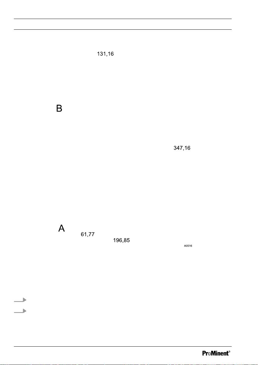
Mounting and Installation
Fig. 1: The diagram is not to scale. It is for information only. All values given in
millimetres.
A Terminal box
B
DULCO® turb C housing
19
Page 20
Mounting and Installation
Fig. 2: The diagram is not to scale. It is for information only. All values given in
millimetres.
A Terminal box
B
DULCO® turb C housing
1. Fasten the terminal box (A) to the wall with two M4 screws
2.
Fasten the DULCO® turb C housing (B) above the terminal box to the wall
with four M6 screws
20
Page 21
4.2 Installation (hydraulic)
Mounting and Installation
Leakage on the bleed screw
CAUTION!
Free outlet at sensor outlet
Feed the sample water which has
flowed through the sensor to a
free drain. The sampled water
may not be fed back into the
process.
CAUTION!
Algae growth under the influence
of light
Possible algae growth if unsuit‐
able hoses are used.
Do not use transparent hoses if
the installation is subjected to
powerful sources of light. This
prevents the formation of algae in
the installation.
Slight leakage may occur at the
bore hole for the bleed screw
during the installation process.
This will cease as soon as normal
flow is established.
In the event that the installation
continues to leak permanently at
this point due to the high pressure
in this area, we recommend
sealing off the bore hole with the
sealing plug supplied. In order to
ensure free drainage, a bleed
option must be installed at
another area of the outlet in order
to avoid overpressure or under‐
pressure in the system.
Permissible operating param‐
eters
–
Maximum liquid temperature
50 °C
–
Maximum pressure 13.8 bar
–
Flow rate 6 ... 60 l/h
21
Page 22

Mounting and Installation
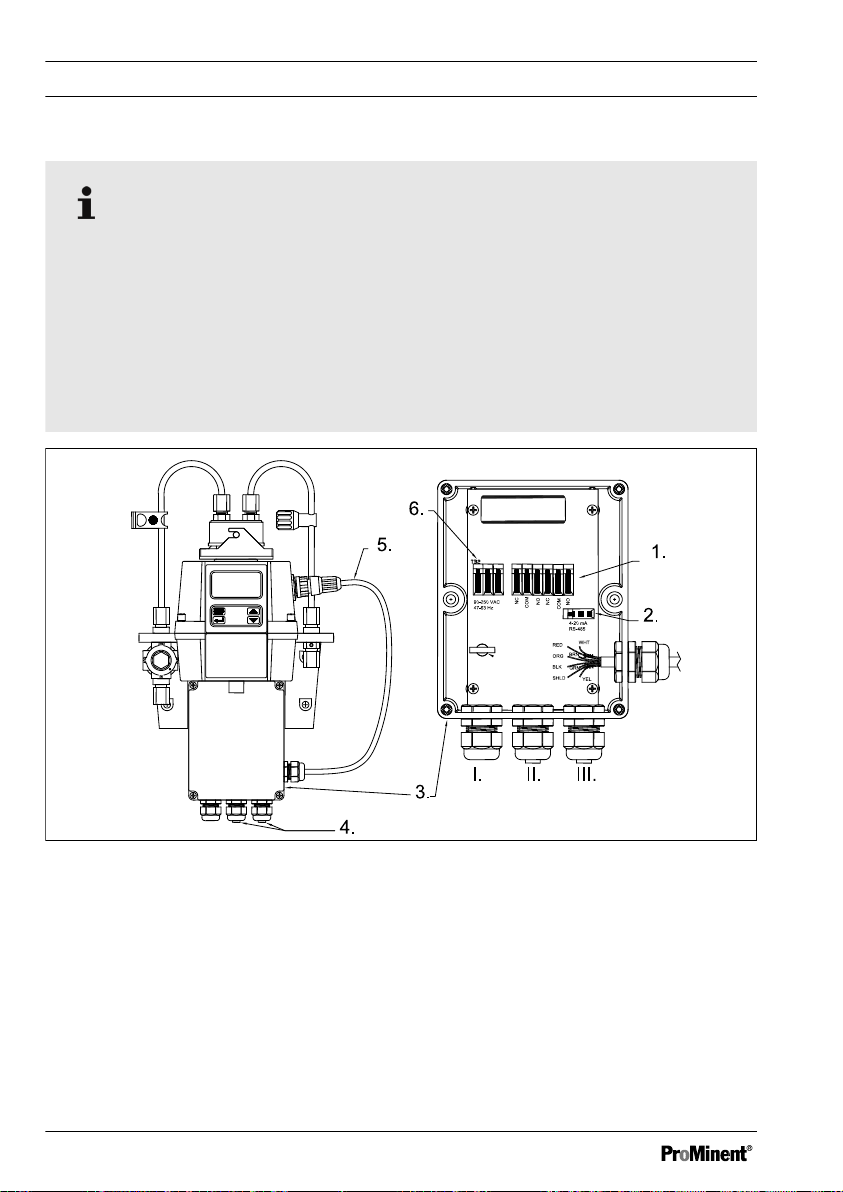
Fig. 3: Recommended pipes for the sensor
I. Flow unit
4. Hose connector. 4.75 mm interior
II. Sensor unit with operating unit
III. Terminal box
1. Backpressure valve. To regulate
the flow and in order to remove
small air bubbles
22
5. Detail: Hose
6. Detail: Union nut hose connection
diameter, 8 mm external diam‐
eter. Hose connection to the sam‐
pling site
Page 23
Mounting and Installation
2. Vent screw. For use on pressur‐
ised systems. Not used for pres‐
sureless systems
3. Hose connector. 4.75 mm interior
diameter, 8 mm external diam‐
eter. Hose connection for free
sample water outlet
4.3 Installation (electrical)
WARNING!
Live parts!
Possible consequence: Fatal or
very serious injuries
– Measure: Disconnect the
power supply before opening
the housing
Disconnect damaged, defec‐
–
tive or manipulated devices
from the power supply
– The provision of a suitable
isolating device (emergencyoff switch, etc.) is the respon‐
sibility of the plant operator
7. Detail: Replacement hose con‐
nection
8. Shut-off clamp. To shut-off the
inlet in an emergency or for nec‐
essary work
The signal leads of the
DULCO® turb C may not be
routed alongside faulty cabling.
Faults could lead to malfunctions
in the DULCO® turb C.
NOTICE!
Do not route any RS-485 cables
in the same cable duct as the
power supply cable. This may
result in major anomalies.
23
Page 24
A0518
Mounting and Installation
RS-485
The RS-485 digital interface (2 leads / half duplex) is characterised by a very
high tolerance to electromagnetic interference due to the symmetrical signal
transmission. This means that cable lengths of up to 900m can be used. The
final device on a bus must be equipped with a 120 ohm resistor, in order to
avoid signal overlapping.
In order to avoid damage, only separate and connect the RS-485 cable if the
DULCO® turb C is switched off.
Fig. 4: Cable assignment of the sensor
I. Power cable threaded connection
(supplied without power cable)
II. Alarm cable threaded connection
III. Sensor cable threaded connec‐
tion
1. Terminal Alarm 1 and Alarm 2
(0.25 - 1.5 mm2) maximum 2
ampere
24
3. Terminal box
4. Liquid-tight threaded connection
5. Sensor cable
6. Terminal power cable (0.25 - 1.5
mm2)
Page 25

Mounting and Installation
2. Terminal 4-20 mA / RS 485 (0.25
- 1.5 mm2)
All terminals in the terminal box are labelled and are self-explanatory.
All cable bushings are equipped with blanks on shipping. These must be
removed as required.
Strip the Insulation on all cables to a length of 6 mm.
Equip all cables with strain relief.
Supply voltage: 100 - 240 VAC at 47 - 63 Hz
1. Release the four housing screws from the corners of the terminal box.
2. Lift off the terminal box cover.
3. Remove the blanks from the required bore holes
4. Guide the cables into the threaded connections
5. Connect the cables with the designated terminals.
6. Tighten the clamping nuts of the threaded connections so that they are
properly sealed
7. Place the terminal box cover back onto the terminal box
8. Manually tighten the housing screws
9. Once again check the seating of the seals and threaded connections. Pro‐
tection class IP 66 is only achieved if the control panel mounting is correct
25
Page 26

Operating diagram
5 Operating diagram
Overview of device /Control elements
5.1
n Users' qualification: Instructed person, see
tions“ on page 8
Fig. 5: Overview of device /Control elements
1. LCD display
2. UP key
4. ENTER button
5. MODE/EXIT button
3. DOWN key
Ä Chapter 1.2 „Users' qualifica‐
Function Description
LCD display The parameters of the respective mode are shown on the
LCD display.
UP key To increase a displayed number
26
Page 27

Operating diagram
Function Description
DOWN key To decrease a displayed number
ENTER button To apply, confirm or save a displayed value or status or
MODE/EXIT
button
In order to call-up and select the three optional modes
[CAL], [CONFIG]
5.2 Overview of operating struc‐
ture
The sensor is equipped with three
modes, which can be selected by
means of the MODE/EXIT button:
n
[AUTO mode]
display of the current measured
values
n
[CAL]
: Calibration mode for exe‐
cuting the calibration process
n
[CONFIG]
configuring customer-specific set‐
tings. Automatic switchover into
the mode
undertaken within 15 minutes
: Standard mode,
: Configuration mode for
[AUTO mode]
if no entry
and
[AUTO]
(measurement)
27
Page 28

Operating diagram
Fig. 6: Overview of operating structure
28
Page 29

Configuration menu
The configuration menu is subdivided
into several submenus, in order to
facilitate configuration.
The following submenus are avail‐
able:
Operating diagram
n Select the output
[O/P]
n Configuration of 4 ... 20 mA inter‐
face
[ERLV]
n Configuration of the alarm
[ALM1 / ALM2]
n Configuration of the offset
[OFST]
n Configuration of access protection
[CODE]
n Extended settings
[EXTD]
The procedure for configuring the
menu settings is described here
Ä Chapter 6.4 „Device configura‐
tion“ on page 35
.
The extended settings are grouped
together in order to prevent accidental
alteration.
n Speed of response
n Screen resolution
n LCD illumination brightness
n Displayed units
n Ultrasonic cleaning
n RS-485 parameters
n Drying agent alarm
[RESP]
[RES]
[BRT]
[UNIT]
[CLN]
[BITS]
[DESC]
The procedure for configuring the
extended settings is described here
Ä Chapter 6.4.5 „Extended set‐
tings“ on page 43
.
29
Page 30

Commissioning
6 Commissioning
Unit NTU (optionally FNU)
NTU (Nephelometric Turbidity Unit) is a unit of measurement for measuring the
turbidity of liquids. Alternatively, the measurement can be expressed as FNU
(Formazine Nephelometric Unit), see
undertaken 1:1.
Measured values over 1000 NTU are outside of the sensor's measurement
range. Measured values over 1100 NTU cause the display to flash and a mes‐
sage to be displayed warning of excessive measured values.
Ä „Units“ on page 48
. The calculation is
During normal operation of the sensor, an arrow is positioned next to
[AUTO]
.
In this state, the lower row indicates the unit of measurement and the upper row
shows the current measured value.
Fig. 7: Display in automatic mode
6.1 Load drying agent
Remove transport mounting
The transport mounting must be removed before initial insertion of the drying
agent bag. This pipe can be subsequently disposed of.
30
Page 31

Commissioning
The DULCO® turb C is equipped with an dehumidifying device. A drying agent
bag in the sensor serves to dry the air. The thermal discharge from the sensor is
used to heat the air. A fan mounted in the inner part of the sensor serves to cir‐
culate the warm air around the optical sleeve and cuvette. The DULCO® turb C
continuously monitors the state of the drying agent bag. As soon as the drying
agent needs to be exchanged, this is indicated in the lower row of the LCD dis‐
play; Warning
[DESC]
(for desiccant). Replacement drying agent bags can be
obtained from Prominent or from your local representative.
Saturated drying agent can cause an alarm to be triggered, in order to indicate
the requirement for exchange. Refer to
Ä „Drying agent alarm“ on page 51
31
Page 32

Commissioning
NOTICE!
Seal sensor housing
Possibility of premature drying agent saturation.
A damaged seal can lead to premature saturation of the drying agent.
Check the seal every time the drying agent is exchanged. Correct the seal
seating or exchange it if necessary.
1. Release the four screws from the corners of the housing and remove the
upper part of the sensor
Fig. 8: Load drying agent
2.
Insert the drying agent immediately after opening the packaging, in
order to avoid premature saturation.
Remove the new drying agent bag (2) from the packaging and place it
together with the humidity indicator card (3) in the lower part of the sensor
(1). In doing so, place the humidity indicator card (3) on the new drying
agent bag (2).
32
Page 33

Commissioning
3. Place the upper part back on the lower part and tighten the four screws
hand-tight.
The sensor must be reset in order to enable detection of the new
ð
drying agent. In order to do so, remove the sensor connection cable
for 2 seconds and then re-connect it. Otherwise the
[DESC]
warning
may be shown on the LCD display.
6.2 Routine measurement
Routine measurement: The turbidity
can be correctly measured approx. 45
- 60 minutes after beginning measure‐
ment / commissioning (warm-up
phase).
If a continuous process water flow
passes through the sensor, then the
sensor shows you the measured tur‐
bidity level of the sample on the LCD
display. In addition, a 4-20 mA signal
or a digital signal is given, depending
on the selected option.
33
Page 34
A0519
Commissioning
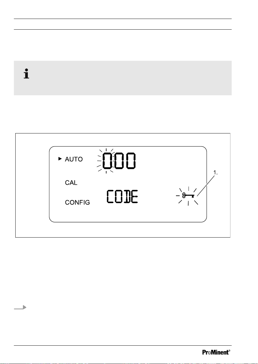
6.3 Access code
The access code cannot be changed.
You can activate the access code for the sensor in the configuration menu. If
the access code is activated, then this is indicated in the lower right-hand sec‐
tion of the LCD display.
[MODE/EXIT button]
„Security“
.
-Symbol (1) displays, if you press the
Fig. 9: Access code
When one of the access code numbers if flashing, you can change the number
with the UP or DOWN button and confirm with the ENTER button.
Entering the access code
The access code (333) has to be entered in order to access the
„CONFIG“
menus.
„CAL“
or
1. The first number of the access code flashes. Select the correct number
with the UP or DOWN button and then press ENTER
The second number of the access code flashes.
ð
34
Page 35
A0530
Commissioning
2. Select the correct number with the UP or DOWN button and then press
ENTER
The third number of the access code flashes.
ð
3. Select the correct number with the UP or DOWN button and then press
ENTER
If you have selected the valid access code, then you will now have
ð
access to the sensor's calibration mode. In the event that the access
code is incorrect, the sensor returns to AUTO mode.
Device configuration
6.4
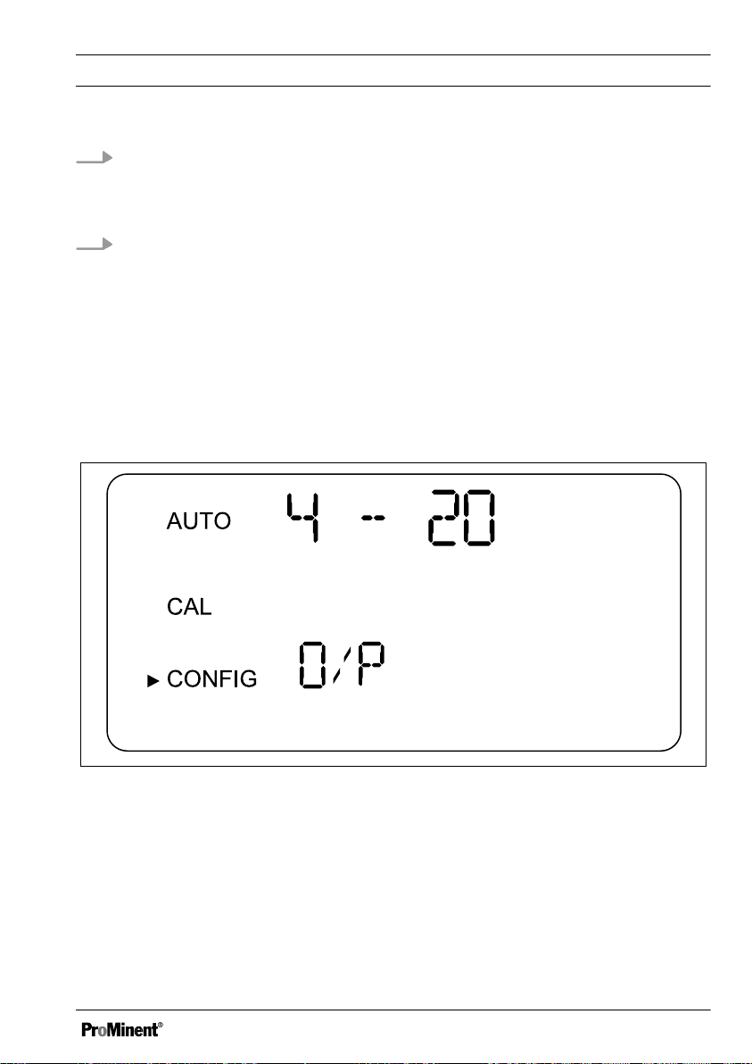
6.4.1 Selecting the output
Fig. 10: Selecting the output
35
Page 36

Commissioning
Function Options Info
Output (O/P)
n 4 - 20 mA
n 485
n off
4 - 20 mA
Value 4 mA 0 ... 1000 NTU Selection of the lower
turbidity limit value
(LOLM)✱, which corre‐
sponds to the output
value 4 mA.
Value 20 mA 0 ... 1000 NTU Selection of the upper
turbidity limit value
(UPLM)✱✱
, which corre‐
sponds to the output
value 20 mA.
✱ = a higher NTU value can be entered than for
„value 20 mA“
, in order to
reverse the sign of the output current
✱✱ = a lower NTU value can be entered than for
„value 4 mA“
, in order to
reverse the sign of the output current
485
Baud Value baud
n 1200
Selection of the baud
rate for the I/O interface
n 2400
n 4800
n 9600
n 19200
36
Page 37
A0625
Commissioning
Function Options Info
Addr 1 ... 255 Selection of the device
address
MBUS ASCII
Selection ASCII or RTU
RTU
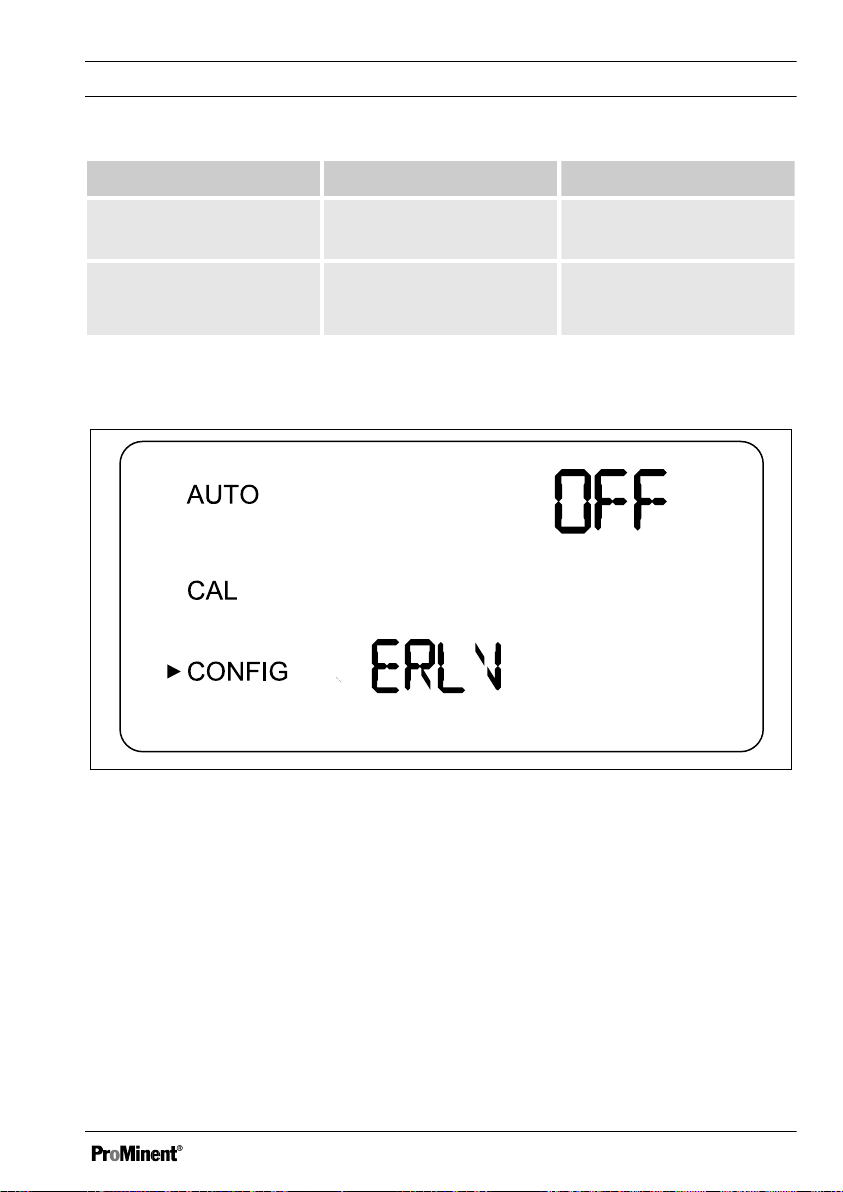
6.4.2 Configuration of fault current (ERLV)
Fig. 11: Configuration of fault current (ERLV)
The 4-20 mA signal output can be utilized in the event of a system error on the
DULCO® turb C in order to indicate the problem by activating the
[ERLV ON]
function. In doing so, fault currents of 4.00 mA, 2.00 mA or 0 mA can be
selected. In the event of an error, the configured current value is output to the
controller, regardless of which measured value is pending. If the function is
switched off by setting
[OFF]
then the 4-20 mA signal output remains unaffected
by fault conditions.
37
Page 38

Commissioning
Select the desired fault current by pressing the buttons ▲
the ↲, in order to store the selected setting.
Function Options Info
Error Level (ERLV) OFF
0 mA
2 mA
4 mA
6.4.3 Configure alarm
Alarm function
The sensor is equipped with two inde‐
pendently programmable alarm
relays. Three items of information
have to be entered in order to fully
configure the alarms:
Alarm triggering in the event
of an internal system error
The relay produces an alarm in
the event of an internal system
n Alarm function: HI, LO, OFF or
ERROR
error, regardless of the configured
turbidity values.
n Alarm limit value (limit value at
which the alarm becomes active)
n Alarm delay time (how long the
limit value must be exceeded
before the alarm is activated and
the period of time before the
alarm is reset)
and ▼ and then press
38
Page 39

Commissioning
You can either deactivate the alarm
(OFF) or program it so that it works in
accordance with one of the following
modes:
n Alarm HI: The relay triggers the
alarm in the event that the tur‐
bidity value exceeds the pro‐
grammed alarm value for at least
the specified period of time
n Alarm LO: The relay triggers the
alarm in the event that the tur‐
bidity value drops below the pro‐
grammed alarm value for at least
the specified period of time
n Alarm ERROR: The relay triggers
the alarm when an internal system
error occurs
Limit value alarm
The turbidity threshold at which the
alarm is triggered is referred to as the
„Limit value alarm“
. You can con‐
figure the limit value across the entire
display range of the device in steps of
0.01 NTU.
Delay period alarm
The alarm delay times prevent the
alarm from being triggered in the
event that the turbidity briefly exceeds
or drops below the threshold value.
The delay function works as follows:
n Delay time
bidity must exceed the
value alarm“
„Alarm on“
: The tur‐
„Limit
for a period of at
least the time configured here,
before the alarm will be triggered.
If the time for
„Delay alarm on“
is
set to 5 seconds and the turbidity
only exceeds
„Limit value alarm“
for 4 seconds, then the alarm will
not be triggered. However, if the
turbidity exceeds the
alarm“
for 5 seconds or longer,
„Limit value
then the sensor triggers an alarm.
n Delay time
bidity must drop below
value alarm“
„Alarm off“
: The tur‐
„Limit
for a period of at
least the number of seconds con‐
figured here, before the alarm will
be triggered. If the time for
alarm off“
is set to 5 seconds and
the turbidity only exceeds
value alarm“
for 4 seconds, then
„Delay
„Limit
the alarm will not be deactivated.
As soon as the turbidity remains
below
„Limit value alarm“
for at
least 5 seconds, the sensor deac‐
tivates the alarm.
39
Page 40
A0531
Commissioning
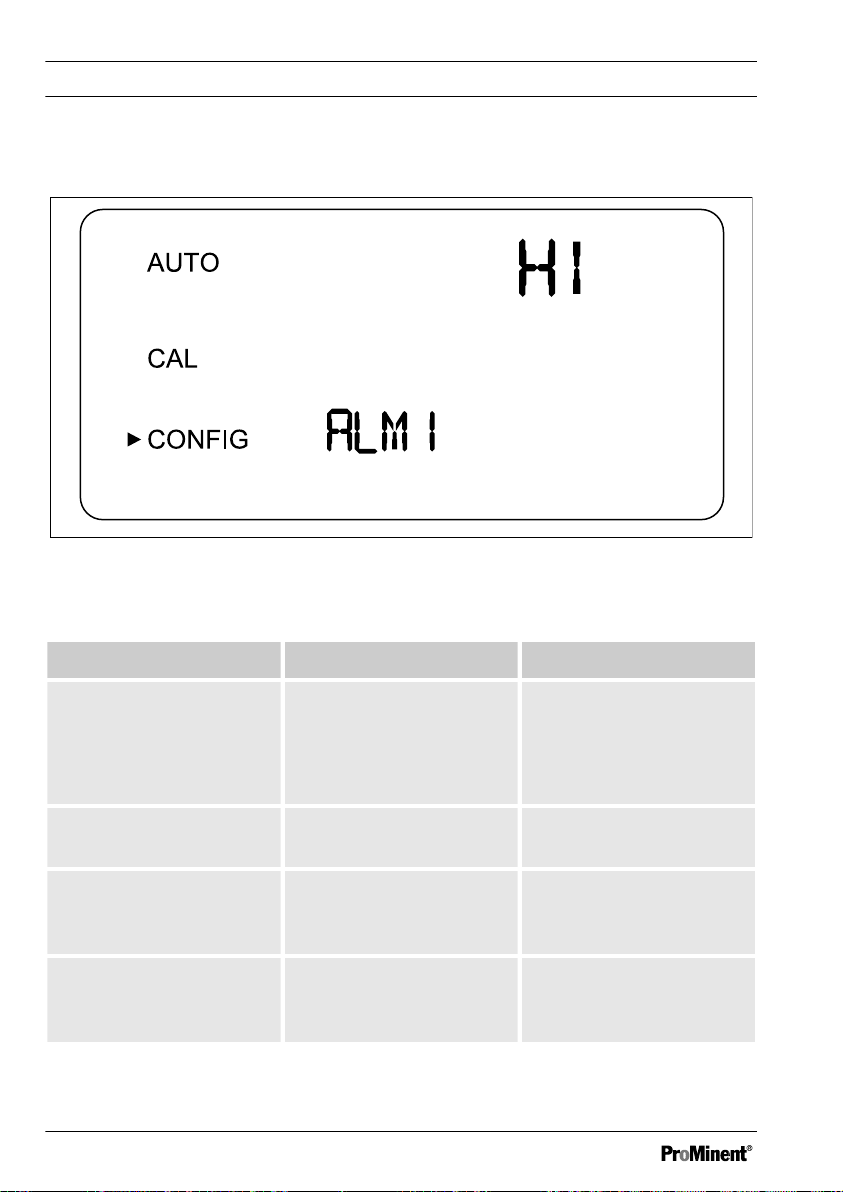
Menu Alarm
Fig. 12: Menu Alarm
Function Options Info
Alarm 1 (ALM1)
or
Alarm 2 (ALM2)
n HI
n LO
n OFF
n ERROR
Select the alarm function
Limit value (S/P) 0 ... 1000 NTU Set the
alarm“
delay time alarm on
(DLY▲)
1 ... 30 s For the function
alarm on“
number of seconds.
Delay time alarm off
(DLY▼)
1 ... 30 s For the function
alarm off“
number of seconds.
40
„Limit value
on
„Delay
set the
„Delay
set the
Page 41
A0624
Commissioning
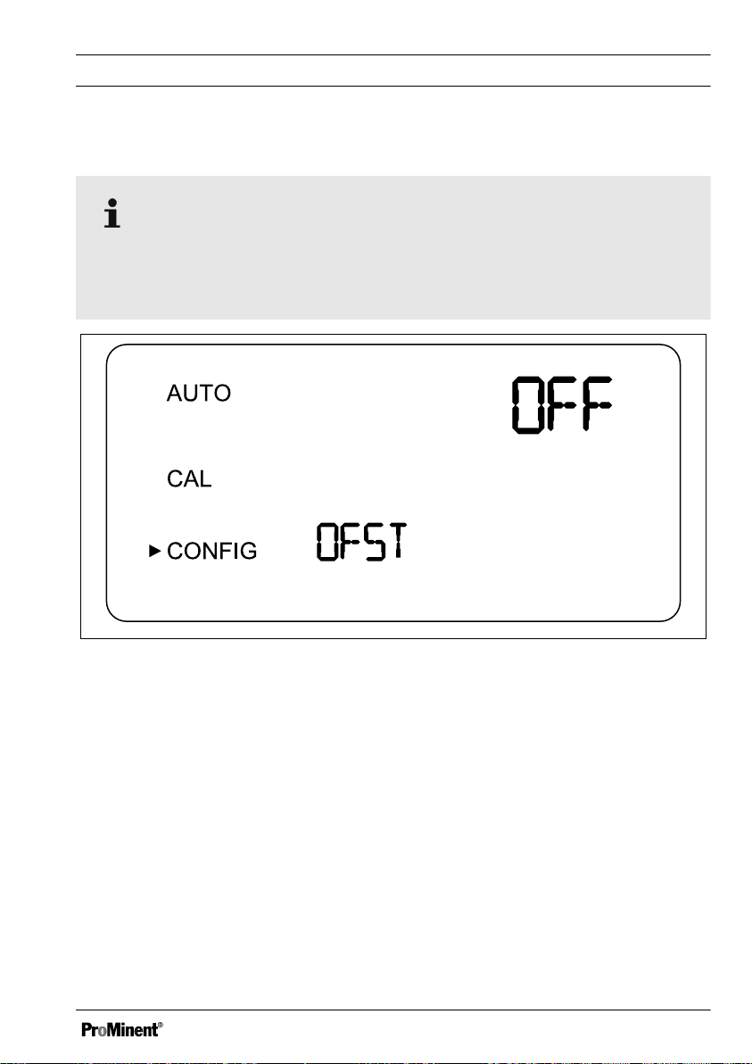
6.4.4 OFFSET configuration
The OFFSET symbol is shows as soon as an offset is being used. The max‐
imum offset amounts to 1.00 NTU. If the device deviation is greater than 1
NTU, then it is recommended to carry out a complete calibration.
Fig. 13: OFFSET configuration
41
Page 42

Commissioning
In certain circumstances it may be desirable to use an offset function in order to
balance the device, instead of performing a complete calibration (as described
under
Ä Chapter 7.1 „Calibrate sensor“ on page 55
). This procedure is not rec‐
ommended as a replacement for regular calibration, however, it can be used in
order to compensate for known minor deviations where measuring operations
cannot be interrupted. This balancing method means that the device only dis‐
plays precise turbidity values in the immediate vicinity of the sample value and
not across the entire measured range.
Proceed as follows in order to configure the offset:
1. Take a sample of the process water being monitored by the device and
make a note of the turbidity as indicated by the device.
2. Measure the turbidity value of the sample with the help of a calibrated
manual laboratory measuring device (reference device)
3. Compare the turbidity value indicated by the device with the value meas‐
ured by the reference device. If the values are extremely close to each
other (depending on the accuracy of the reference device), then no offset
configuration or calibration is required and the procedure can be aborted
at this point.
However, if the values differ significantly (however, less than 1 NTU),
ð
then proceed as follows in order to improve the turbidity value for the
device, so that the device matches the laboratory value.
4. Select the offset function by pressing
is positioned next to
5. Press the key ↲, until
At this point, the upper row of the display indicates the operating con‐
ð
[CONFIG]
[OFST]
is shown in the lower row
[MODE/EXIT button]
dition of the offset function.
6. If the function is switched off, then switch it
7. Select the desired offset value with ▼ or ▲
Press the key ↲, to accept the value.
ð
42
until the arrow
[ON]
, by pressing ▼ or ▲ .
Page 43

A0532
Commissioning
The difference between the value measured by the DULCO® turb
C NTU-value and the value measured by the reference device is
the offset value.
For example, if the DULCO® turb C measures a value of 0.016
NTU for the process water, and the reference device measures a
value of 0.012 NTU for the sample, then entering an offset value of
-0.04 will cause the DULCO® turb C to display the value 0.012
NTU
8. At this point, the offset configuration is completed. At this stage, the device
remains in configuration mode
[MODE/EXIT button]
in order to return to
[CONFIG]
. Press the key
[AUTO]
6.4.5 Extended settings
Extended settings
Fig. 14: Extended settings
43
Page 44

A0533
Commissioning
Function Options Info
[ON]
[OFF]
(On)
(Off)
Select the function
"Extended settings" in
order to access configu‐
Extended settings
ration for the following
options:
n Speed of response
n Screen resolution
n LCD illumination
n Units
n Ultrasonic cleaning
n RS-485 parameters
n Alarm drying agent
brightness
Response time
Fig. 15: Response time
44
Page 45

Function Options Info
Commissioning
Reaction time
(RESP)
1 ... 100 %
Factory setting: 10
%
Select a reaction time for the dis‐
played and output NTU values.
Select the highest reaction time (i.e.
the highest number) in order to avoid
anomalies caused by air or other influ‐
ences.
Select the lowest reaction time (i.e.
the lowest number) if rapid changes
are to be expected, which are to be
monitored.
The displayed number is a relative
reaction time. The approximate reac‐
tion time (in seconds) can be calcu‐
lated by the displayed number multi‐
plied by 5.
45
Page 46

A0534
Commissioning
Screen resolution
Fig. 16: Screen resolution
Function Options Info
Screen resolution (RES) 1 ... 0.001
Factory setting: 0,01
For displayed values
under 10 NTU the
DULCO® turb C is able
to display a value with
up to four digits after the
decimal point
46
Page 47

LCD illumination brightness
A0535
Fig. 17: LCD illumination brightness
Commissioning
Function Options Info
LCD illumination bright‐
ness (BRT)
1 ... 10
Factory setting: 8
Adjust the backlighting
for the LCD display as
required
47
Page 48
A0536
Commissioning
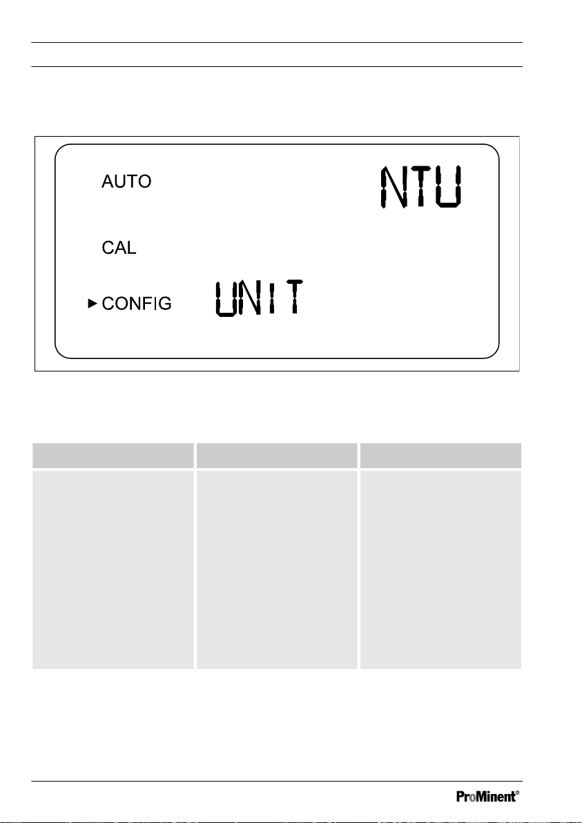
Units
Fig. 18: Units
Function Options Info
Units (UNIT)
n NTU
n FNU
Select a unit for dis‐
playing the turbidity
measurement:
Factory setting: NTU
NTU
[Nephelometric Turbidity
Units]
or
FNU
[Formazin Nephelo‐
metric Units]
48
Page 49
A0537
Commissioning
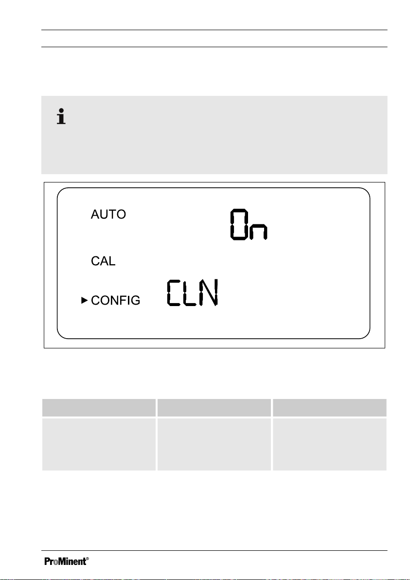
Ultrasonic cleaning (models TUC 3 and TUC 4)
Error message in the event of incorrect cuvette
Only active if a corresponding cuvette with ultrasound transducer is used. If
you use a cuvette without an ultrasound transducer, then an error message
will be shown on the LCD display.
Fig. 19: Ultrasonic cleaning
Function Options Info
Ultrasonic cleaning
(CLN)
[ON]
(On)
[OFF]
(Off)
Factory setting:
[ON]
If the ultrasonic cleaning function is working normally
Switching the ultrasonic
cleaning function on and
off
„AUTO“
matic measuring mode (AUTO)
flashes in auto‐
49
Page 50
A0538
Commissioning
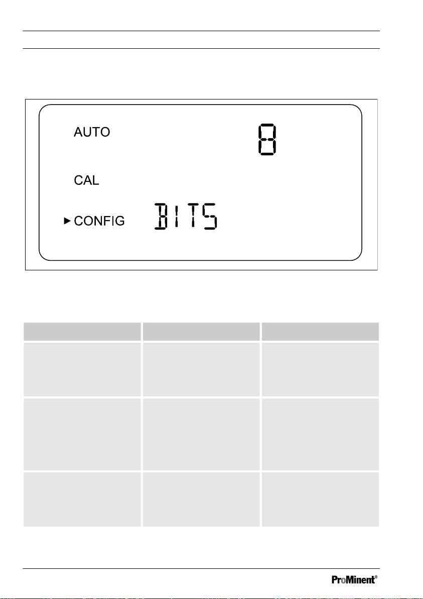
RS-485 parameters
Fig. 20: RS-485 parameters
Function Options Info
Bits (BITS) 7
8
Factory setting: 8
Parity (PRTY) nOnE
ODD
The required number of
data bits for the commu‐
nications software
deployed
The parity bit required
for the communications
software.
E
Factory setting: nOnE
Stop 1
2
The stop bit required for
the communications
software.
Factory setting: 1
50
Page 51
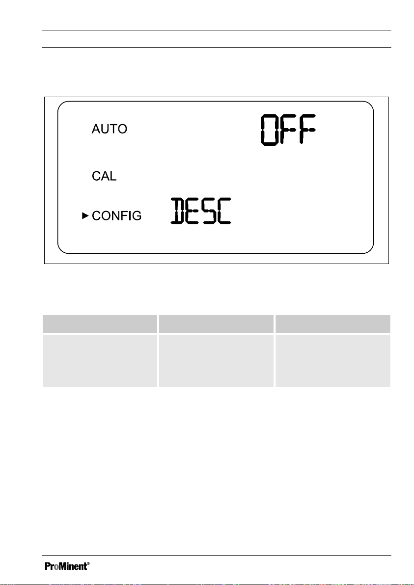
Drying agent alarm
A0539
Fig. 21: Drying agent alarm
Commissioning
Function Options Info
Drying agent alarm
(DESC)
[ON]
(On)
[OFF]
(Off)
Factory setting:
[OFF]
In order to activate one or both alarms, then you must configure
Ä Chapter 6.4.3 „Configure alarm “ on page 38
.
In order to indicate an error via the 4-20 mA signal,
must be selected in alarm current, see
“ on page 38
.
Ä Chapter 6.4.3 „Configure alarm
Select
[ON,]
in order to
trigger an alarm when
the drying agent is satu‐
rated
„ERROR“
, see
„ERROR ALARM (ERLV)“
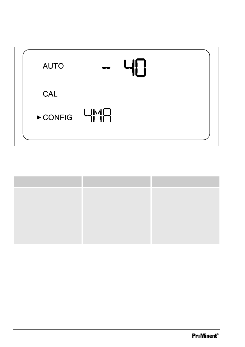
Configuration of 4 mA output
Allow a constant output of 4 mA and will allow you to calibrate or adjust the 4
mA signal.
51
Page 52
A0607
Commissioning
Fig. 22: Configuration of 4 mA output
Function Options Info
Configuration of 4 mA
output
- 40 ... + 40 Configure the mA value
in order to adapt to the
superordinated control
system (e.g. SPC or
SCADA)
One count number cor‐
responds to 0.01 mA
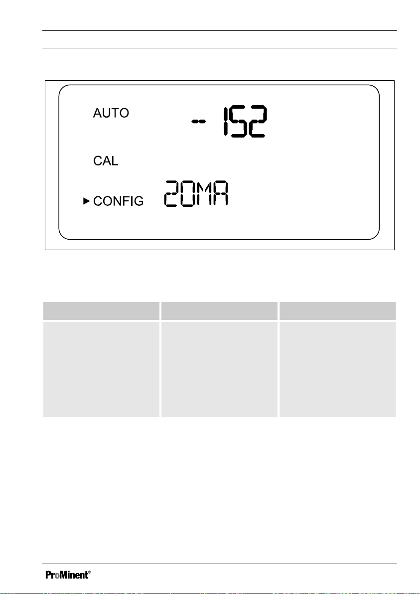
Configuration of 20 mA output
Allow a constant output of 20 mA and will allow you to calibrate or adjust the 20
mA signal.
52
Page 53
A0608
Fig. 23: Configuration of 20 mA output
Function Options Info
Commissioning
Configuration of 20 mA
- 1000 ... + 1000 Configure the mA value
output
Save configuration settings
If you have set the extended settings
(EXTD) to
the
[↲]
„OFF“
then you can use
-button to save the settings and
return to the permanent display in
„AUTO“
mode, see figure Fig. 6
in order to adapt to the
superordinated control
system (e.g. SPC or
SCADA)
One count number cor‐
responds to 0.01 mA
53
Page 54

Commissioning
If you have set the extended settings
„ON“
(EXTD) to
[↲]
-button after the final menu in the
then you can use the
extended settings to save your set‐
tings and return to the permanent dis‐
play in
„AUTO“
mode, see figure
Fig. 6. All changes previously under‐
taken in the configuration menu can
be stored in this manner.
You can access the configuration
menu at any time in order to reset or
modify some or all of the parameters.
You can exit the configuration menu
at any time by pressing the
[MODE/EXIT button]
. In doing so,
any changes to the parameters that
you have modified will be stored.
Flow controller
The flow controller (part number
1037880) limits high-pressure sys‐
tems to a flow of less than 1 l/min.
54
Page 55

7 Operation
Operation
7.1 Calibrate sensor
The sensor was tested and cali‐
brated before leaving the factory.
For this reason, you can use the
sensor right away. Under normal
conditions, it is recommended to
carry out calibration at least once
every three months.
The alarm relay switches over to
alarm state if the sensor is in
[CAL] or [CONFIG] mode. If no
entry is made in [CAL] mode
within a period of 15 minutes, the
sensor automatically toggles back
over to [AUTO] mode.
7.1.1 Standard solutions for cali‐
bration
If you operate the sensor across
its entire measurement range
from 0.02 NTU to 1000 NTU, then
you must perform calibration with
all three standard solutions (0.02
NTU, 10.0 NTU and 1000 NTU). If
the sensor is only operated in
measurement ranges under 10
NTU, then you may perform a
simplified calibration with standard
solutions 0.02 NTU and 10.0
NTU.
55
Page 56

Operation
CAUTION!
Use of diluted formazine
Possible consequences: Inaccu‐
rate calibration. Malfunctions in
dependent processes.
Diluted formazine is instable.
Ensure that freshly prepared for‐
mazine solution is used when per‐
forming calibration.
If possible, use a standard solu‐
tion from Prominent for calibra‐
tion. These standard solutions are
more stable than formazine and
have a minimum shelf-life of 12
months. In doing so, observe the
use-by-date on the standard solu‐
tion packaging.
Indexing the standard solution with
your cuvette
CAUTION!
Malfunction of the control circuit
Possible consequence: Poor endproduct quality
Ensure that your controller or
other measuring equipment is
configured so that the indexing
process does not lead to uninten‐
tional control functions in the
measurement and control system.
The controller connected to the
sensor may not process the sig‐
nals and use them for control pur‐
poses during indexing of the sig‐
nals.
Calibration set order number:
1037699
56
NOTICE!
Screen resolution
We recommend indexing the
DULCO® turb C in the "Commis‐
sioning / Display resolution"
menu, so that the following resolu‐
tion is achieved
1000 NTU: No digits after the
–
decimal point on the display
– 10 NTU: Two digits after the
decimal point on the display
– 0.02 NTU: Four digits after the
decimal point on the display
Page 57

Operation
Handling the standard solu‐
tion
The standard solution 1000 NTU
must be lightly shaken before use
for calibration.
Standard solution 10 NTU must
be transferred to the cuvette from
the supply bottle before it is used
for the first time. The filling for the
10 NTU cuvette is then usable for
3 months.
Do not use the standard solution
once the use-by-date has expired.
Purpose of indexing
The standard solution cuvettes
have minimal manufacturing toler‐
ances. This results from the man‐
ufacturing process and is unavoid‐
able.
In order to minimise the effects of
these manufacturing tolerances
on the calibration process, you
must index and mark the position
on the cuvette with the lowest tur‐
bidity value (lowest NTU value).
You can mark the index points
with the help of the marking rings
supplied. These marking rings are
included with the calibration set
packaging. The marking ring must
first be placed around the plastic
cover of the respective cuvette.
57
Page 58

Operation
Prerequisites: The sensor is opera‐
tional and is switched to
[AUTO]
mode.
1. Open the flow unit by screwing
it clockwise and remove the inline flow fitting from the cuvette.
2. Place the
[1000 NTU]
calibra‐
tion cuvette in the DULCO® turb
C
3. Rotate the
[1000 NTU]
calibra‐
tion cuvette one full turn in 20°
steps. On each step, wait until
the displayed measured value
has stabilised.
Mark the point on the cuv‐
ð
ette with the lowest NTU
value with the help of the
marking ring supplied, so
that the marker points
towards yourself.
4. Remove the
[1000 NTU]
calibra‐
tion cuvette and place the
[10 NTU]
calibration cuvette in
the DULCO® turb C
6. Remove the
[10 NTU]
calibra‐
tion cuvette and place the
[0.02 NTU]
calibration cuvette in
the DULCO® turb C
7. Rotate the
[0.02 NTU]
calibra‐
tion cuvette one full turn in 20°
steps. On each step, wait until
the displayed measured value
has stabilised.
Mark the point on the cuv‐
ð
ette with the lowest NTU
value with the help of the
marking ring supplied, so
that the marker points
towards yourself.
8. Place the cuvette sample with
the cuvette into the DULCO
®
turb C
9. Close the in-line flow fitting by
screwing it in an anticlockwise
direction.
ð
The DULCO® turb C is in
[AUTO]
mode.
5. Rotate the
[10 NTU]
cuvette one full turn in 20°
steps. On each step, wait until
the displayed measured value
has stabilised.
Mark the point on the cuv‐
ð
ette with the lowest NTU
value with the help of the
marking ring supplied, so
that the marker points
towards yourself.
58
calibration
For subsequent calibra‐
tion, place the calibra‐
tion cuvette into the
DULCO® turb C so that
the marking ring marker
points towards yourself.
Page 59

Operation
7.1.2 Perform calibration
CAUTION!
Malfunction of the control circuit
Possible consequence: Poor end-product quality
Ensure that your controller or other measuring equipment is configured so
that the calibration process does not lead to unintentional control functions
in the measurement and control system. The controller connected to the
sensor may not process the signals and use them for control purposes
during calibration of the signals.
NOTICE!
Fan standstill
The sensor fan is switched off during the calibration process, in order to
extend the service life of the drying agent.
The fan is switched on:
during the calibration countdown
–
– after returning to
[AUTO]
mode.
– After 5 minutes without input from the operator
– Whichever occurs first.
Keep the measurement chamber covered if no cuvette is inserted and only
place a cuvette into the measurement chamber if it is completely dry, in
order to avoid premature saturation of the drying agent.
59
Page 60

Operation
NOTICE!
Cleaning the cuvette
Possibility measurement value distortion
Before inserting the respective cuvette, it must be thoroughly cleaned with
the cleaning cloth provided with the calibration set. Even minimal traces of
foreign bodies on the surface of the cuvette can cause the measured result
to be falsified.
Prerequisites: The sensor is operational and is switched to
[AUTO]
mode.
Fig. 24: Display [Calibration 1000 NTU]
1. Use the
ð
[MODE/EXIT button]
key to select
[CAL]
mode.
The LCD display (see Fig. 24) shows an arrow next to
[CAL]
. The
lower display value (1000) is the selected calibration point. The upper
displayed value is the currently measured NTU value.
2. Open the flow unit by screwing it in a clockwise direction and remove the
cuvette sample together with the cuvette.
60
Page 61

A0523
Operation
3.
Place the
[1000 NTU]
calibration cuvette in the DULCO® turb C so that the
marking ring marker points towards yourself, see
Ä „Indexing the standard solution with your cuvette“ on page 56
4. Slowly rotate the calibration cuvette 20° from the centre point to the left
and then 20° from the centre point to the right
Leave the calibration cuvette in the position with the lowest measured
ð
value.
Fig. 25: Display [Start calibration ]
5. Press the ↲-key in order to start calibration to
ð
A 30 second countdown begins, after which the DULCO® turb C is
calibrated to
[1000 NTU]
.
[1000 NTU]
61
Page 62

A0525
Operation
Fig. 26: Display [Calibration 10 NTU]
6. Remove the
7.
Place the
[1000 NTU]
[10 NTU]
Calibration cuvette
calibration cuvette in the DULCO® turb C so that the
marking ring marker points towards yourself, see
Ä „Indexing the standard solution with your cuvette“ on page 56
8. Slowly rotate the calibration cuvette 20° from the centre point to the left
and then 20° from the centre point to the right
Leave the calibration cuvette in the position with the lowest measured
ð
value.
62
Page 63

A0524
Fig. 27: Display [Start calibration ]
A0526
Operation
9. Press the ↲-key in order to start calibration to
ð
A 60 second countdown begins, after which the DULCO® turb C is
calibrated to
[10 NTU]
.
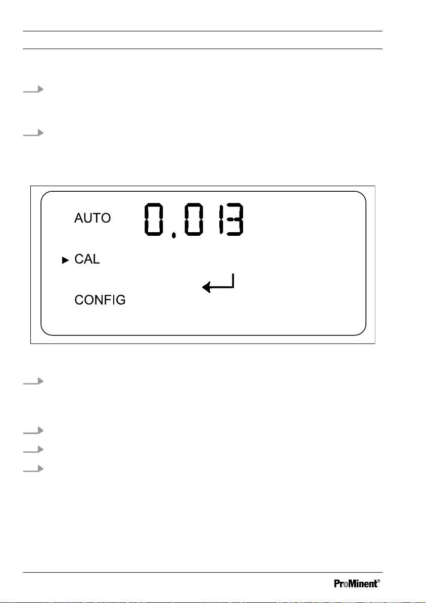
Fig. 28: Display [Calibration 0.02 NTU]
10. Remove the
[10 NTU]
Calibration cuvette
[10 NTU]
63
Page 64
A0527
Operation
11.
Place the
[0.02 NTU]
calibration cuvette in the DULCO® turb C so that the
marking ring marker points towards yourself, see
Ä „Indexing the standard solution with your cuvette“ on page 56
12. Slowly rotate the calibration cuvette 20° from the centre point to the left
and then 20 ° from the centre point to the right
Leave the calibration cuvette in the position with the lowest measured
ð
value.
Fig. 29: Display [Start calibration ]
13. Press the ↲-key in order to start calibration to
[0.02 NTU]
ð
A 30 second countdown begins, after which the DULCO® turb C is
calibrated to
14.
Remove the
15.
Place the cuvette sample with the cuvette into the
[0.02 NTU]
[0.02 NTU]
.
calibration cuvette from the DULCO® turb C
DULCO® turb C.
16. Close the in-line flow fitting by screwing it in an anticlockwise direction
ð
The DULCO®
turb C is now calibrated and is returned to
[AUTO]
mode.
64
Page 65
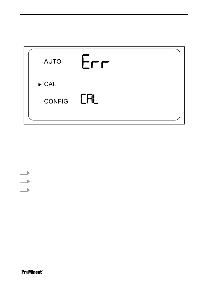
Incorrect calibration
A0528
Fig. 30: Display [Incorrect calibration]
If the
[Err CAL]
message is shown, then the DULCO® turb C internal diagnostics
system has determined that an error has occurred during calibration.
Operation
Press the
[MODE/EXIT button]
in order to repeat the calibration process.
Restoring the factory calibration settings
1. In order to restore the factory calibration, press and hold the ▲-key
2. Now press the ↲-key and release it again
3. Now release the ▲-key.
The sensor will now work with the factory calibration values.
ð
65
Page 66

Maintenance, troubleshooting and repair
8 Maintenance, troubleshooting and repair
8.1 Information about fault main‐
tenance
The sensor continuously carries out
self-diagnostic checks. Any errors are
displayed in the bottom row of the dis‐
play.
The sensor has a three-stage fault
detection system:
n Warning
A warning is merely a mes‐
–
sage on the display which
serves to indicate a pending
problem. No alarms are
issued. For example, if the
drying agent alarm is deacti‐
vated and the drying agent is
saturated, the LCD display
shows the following warning:
[DESC]
n Fault
– An error indicates a malfunc‐
tion or problem which can
generally be rectified by the
operator. This includes, for
example, a lamp failure
[LAMP]
[CAL]
or incorrect calibration
. If an error occurs, the
sensor continues to indicate
values, however, the accuracy
of these measured values is
uncertain, meaning that you
cannot rely on the values
given.
n Malfunction
A malfunction is a system
–
error. This problem cannot be
rectified by the operator. The
sensor must be sent back to
the factory for repair. These
faults relate to malfunctions in
the
[CPU], [A/D], [EEPROM]
or other units, which are inte‐
grated into the sensor. In the
case of malfunction, the
device will no longer work cor‐
rectly and the message
will be shown on the LCD dis‐
play. Both alarm relays are
activated and the current
output is set to 2 mA.
[FAIL]
66
Page 67

8.1.1 System error messages
Maintenance, troubleshooting and repair
Fault mes‐
Possible cause Measure
sage
[MA]
[DESC]
4 ... 20 mA circuit open Check cabling
Drying agent saturated Exchange drying agent. Refer
to
Ä Chapter 6.1 „Load drying
agent“ on page 30
[LAMP]
Lamp failure Exchange lamp. Contact cus‐
tomer service
[FLOW]
[CLN]
Flow interrupted Establish flow
Cuvette ultrasound trans‐
ducer has no contact
Rotate the cuvette slightly in
order to improve contact.
Exchange the cuvette if the
problem persists.
Cuvette removed Insert cuvette
[FAIL]
Fatal system errors Contact customer service
8.1.2 Faults in the process
Fault Possible cause Process error
Displayed
values higher
Air bubbles in the
sample water
than expected
Condensate or cuvette
not airtight
Cuvette soiled Clean cuvette
Ensure that the outlet bleed valve is
open and not blocked
Create backpressure
Install air bubble trap, accessories,
order number 1037790
Check cuvette for condensate or
leaks
67
Page 68

Maintenance, troubleshooting and repair
Fault Possible cause Process error
Displayed
values incor‐
rect
Displayed
values lower
than expected
Upper row of
display
flashes
Sensor not correctly
calibrated
Air bubbles in the
sample water
Particles of dirt in the
cuvette
Sensor not correctly
calibrated
Sample has exceeded
the permissible meas‐
urement range
Calibrate sensor, see
Ä Chapter
7.1.2 „Perform calibra‐
tion“ on page 59
Ensure that the outlet bleed valve is
open and not blocked
Create backpressure
Install air bubble trap, accessories,
order number 1037790
Clean the cuvette of any particles of
dirt.
Calibrate sensor, see
Ä Chapter
7.1.2 „Perform calibra‐
tion“ on page 59
Check sample. Turbidity of the
sample may be too high in order to
be read by the sensor
68
Page 69

Spare parts and accessories
9 Spare parts and accessories
Spare parts
Spare part Part number
Drying agent 1037701
Cuvette TUC1 / TUC2 1037877
Cuvette TUC3 / TUC4 1037878
Infrared lamp TUC1 / TUC3 1037702
White light lamp TUC2 / TUC4 1037703
Hose kit 1037879
Pressure regulating valve 1037885
Accessories
Accessories Part number
Calibration set 1037699
Flow controller 1037880
Air bubble trap 1037700
69
Page 70

Standards complied with
10 Standards complied with
EN 60529 Specification for degrees of
protection provided by enclosures (IPCode)
EN 60746-1 Expression of perform‐
ance of electrochemical analyzers Part 1: General
EN 61000 Electromagnetic compati‐
bility (EMC)
EN 61010 Safety requirements for
electrical equipment for measure‐
ment, control and laboratory use Part 1: General requirements
EN 61326 Electrical equipment for
measuring, control and laboratory use
- EMC requirements (for class A and
B devices)
70
Page 71

11 Disposal of used parts
n Users' qualification: instructed
persons, see
„Users' qualifications“ on page 8
NOTICE!
Regulations governing disposal of
used parts
– Note the current national reg‐
ulations and legal standards
which apply in your country
ProMinent Dosiertechnik GmbH, Hei‐
delberg will take back decontami‐
nated used devices providing that
they are covered by adequate
postage.
Ä Chapter 1.2
Disposal of used parts
71
Page 72
Declaration of Conformity
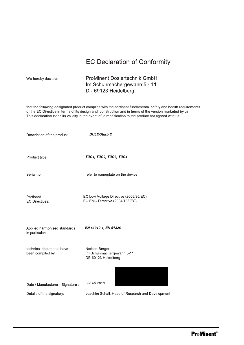
12 Declaration of Conformity
Fig. 31: Declaration of Conformity
72
Page 73

13 Index
Index
A
Accessibility................................... 17
Accessories................................... 69
Alarm delay period........................ 39
Alarm ERROR............................... 39
Alarm function............................... 38
Alarm HI........................................ 39
Alarm limit value............................ 39
Alarm LO....................................... 39
Alarm menu................................... 40
Ambient temperature..................... 17
C
Calibration erroneous.................... 65
D
Data................................................. 6
Delay period alarm........................ 39
F
Flow............................................... 21
FNU............................................... 30
Functions......................................... 6
G
General non-discriminatory
approach......................................... 3
I
Incorrect calibration....................... 65
L
Limit value alarm........................... 39
Liquid temperature........................ 21
M
Menu Alarm................................... 40
Mounting position.......................... 17
N
non-discriminatory approach........... 3
NTU............................................... 30
O
Operating position......................... 17
P
Pressure........................................ 21
Protection class IP 66 ...................
25
R
Radiant exposure.......................... 17
Reading position............................ 17
Recycling................................. 16, 17
S
Safety information........................... 6
Spare parts.................................... 69
Strain relief.................................... 24
T
Turbidity threshold......................... 39
U
Unit NTU ....................................... 30
Users' qualifications......................... 8
73
Page 74

Page 75

Page 76

 Loading...