

Page 1
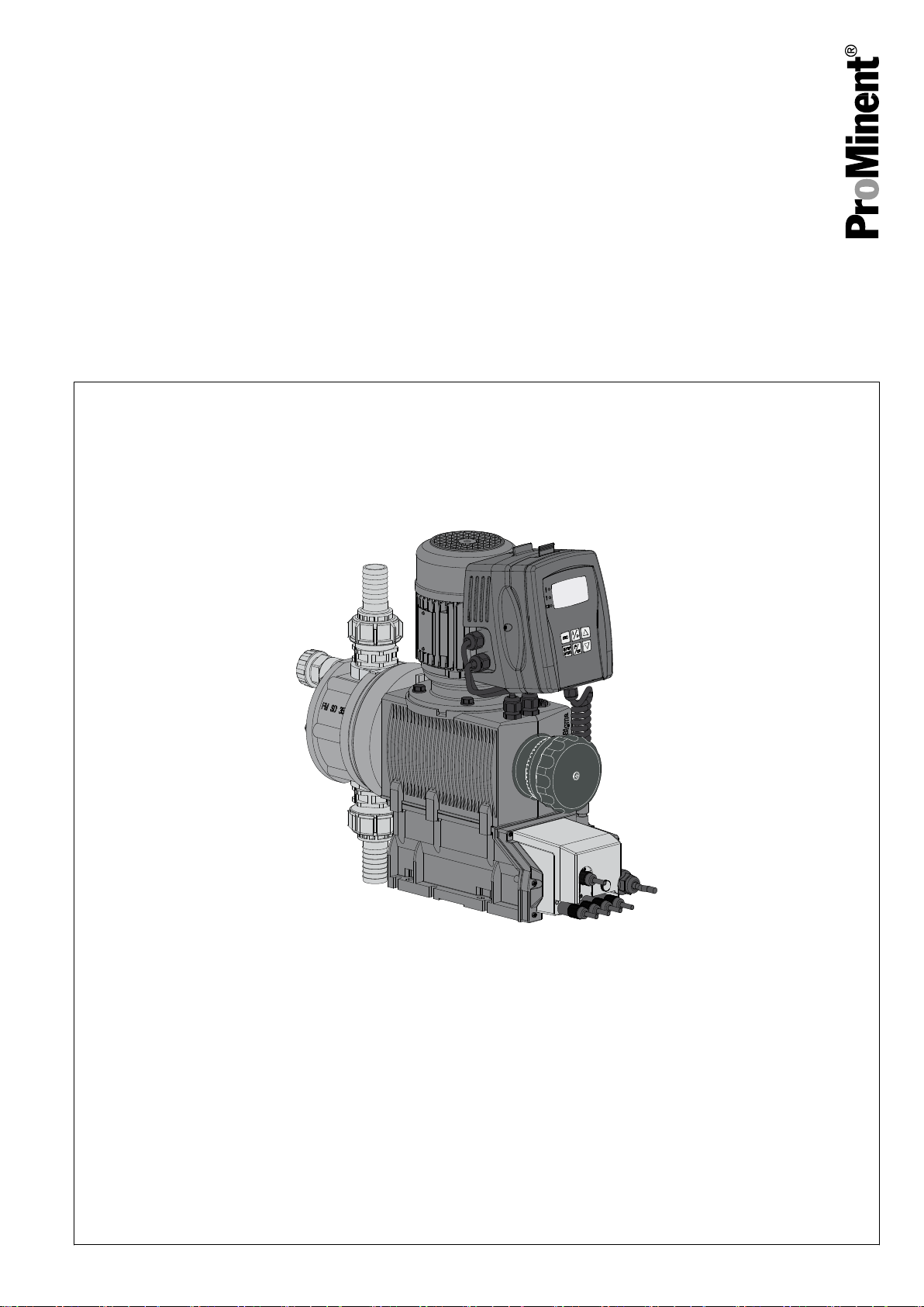
Operating instructions
Diaphragm Motor-driven Metering Pump
Sigma/ 2 Control type S2Cb
EN
Please carefully read these operating instructions before use. · Do not discard.
The operator shall be liable for any damage caused by installation or operating errors.
The latest version of the operating instructions are available on our homepage.
Original Operating Instructions (2006/42/EC)Part no. 985454 BA SI 073 03/17 EN
Page 2

Supplemental directives
Supplementary information
Fig. 1: Please read!
Read the following supplementary information in its entirety! Should you
already know this information, you will benefit more from referring to the
operating instructions.
The following are highlighted separately in the document:
n Enumerated lists
Handling instructions
Outcome of the operation guidelines
ð
- see (reference)
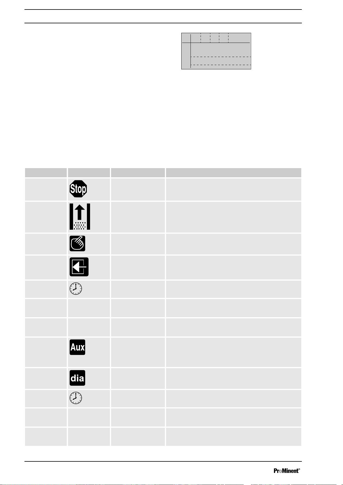
Information
This provides important information relating to the cor‐
rect operation of the device or is intended to make your
work easier.
Validity
State the identity code and serial number
Safety notes
Safety notes are identified by pictograms - see Safety Chapter.
At the time of going to press, these operating instructions conformed to the
current EU regulations.
Please state identity code and serial number, which you can find on the
nameplate when you contact us or order spare parts. This enables the
device type and material versions to be clearly identified.
2
Page 3

Table of contents
Table of contents
Identity Code................................................................................... 5
1
2 Safety Chapter................................................................................. 8
3 Storage, Transport and Unpacking................................................ 12
4 Overview of equipment and control elements............................... 13
4.1 Key functions......................................................................... 15
4.2 LCD screen identifiers........................................................... 15
5 Functional Description................................................................... 18
5.1 Pump..................................................................................... 18
5.2 Liquid end.............................................................................. 19
5.3 Bleed valve and integrated relief valve ................................ 19
5.4 Multi-layer safety diaphragm................................................. 20
5.5 Operating modes................................................................... 20
5.6 Functions............................................................................... 21
5.7 Options.................................................................................. 22
5.8 Function and fault indicator................................................... 22
5.9 LCD screen........................................................................... 23
5.10 LED Displays....................................................................... 23
5.11 Hierarchy of operating modes, functions and fault sta‐
tuses....................................................................................
6 Assembly....................................................................................... 24
7 Installation..................................................................................... 26
7.1 Installation, hydraulic............................................................. 26
7.1.1 Basic installation notes....................................................... 30
7.2 Installation, electrical............................................................. 31
7.2.1 Control connectors............................................................. 32
7.2.2 HMI operating unit.............................................................. 39
7.2.3 Pump, power supply........................................................... 40
7.2.4 Other units.......................................................................... 41
8 Setting........................................................................................... 42
8.1 Basic Principles for Setting up the Control............................ 42
8.2 Checking adjustable values / error messages...................... 42
8.3 Changing to set up mode...................................................... 43
8.4 Selecting the operating mode (Menu "Mode")...................... 44
8.5 Operating mode settings (menu "Settings").......................... 44
8.5.1 "Manual" operating mode settings..................................... 45
8.5.2 "Batch" mode settings ....................................................... 45
8.5.3 "Contact" operating mode settings..................................... 46
8.5.4 "Analog" operating mode settings...................................... 49
8.6 Programmable function settings ("Settings" menu ).............. 52
8.6.1 “Auxiliary frequency” function settings (AUX menu)........... 52
8.6.2 Settings for the “Calibration” function (CALIBRATION
menu).................................................................................
8.6.3 Settings for the “Metering” function (DOSING menu)........ 54
8.6.4 Settings for the “Dosing monitor” function (DOSING
MONITOR menu)............................................................... 56
8.6.5 Settings for the “Relay” function (RELAY menu)................ 57
8.6.6 Settings for the “Analog output” function (ANALOG
OUTPUT menu)................................................................. 58
8.6.7 Settings for the “Diaphragm break” function (DIA‐
PHRAGM BREAK menu)................................................... 59
8.6.8 Settings in the "System" menu" (SYSTEM menu)............. 59
8.7 Service (SERVICE menu)..................................................... 59
8.7.1 Clear counters (CLEAR COUNTERS menu)..................... 60
8.7.2 Adjusting the Display (DISPLAY menu)............................. 60
23
53
3
Page 4

Table of contents
8.7.3 HMI logout.......................................................................... 60
8.7.4 Security (SECURITY menu)............................................... 61
8.8 Information about the pump (INFORMATION menu)............ 62
8.9 Set language (LANGUAGE menu)........................................ 62
9 Start Up......................................................................................... 64
10
Operation....................................................................................... 67
10.1 Manual................................................................................ 67
10.2 Remote operation................................................................ 69
11 Maintenance.................................................................................. 70
Carrying out repairs....................................................................... 73
12
12.1 Cleaning valves................................................................... 73
12.2 Replacing the diaphragm.................................................... 75
13 Troubleshooting............................................................................. 79
13.1 Faults without a fault message............................................ 79
13.2 Fault messages................................................................... 80
13.3 Warning messages............................................................. 81
13.4 All Other Faults................................................................... 82
14 Decommissioning.......................................................................... 83
15 Technical data............................................................................... 86
15.1 Performance data................................................................ 86
15.2 Viscosity.............................................................................. 87
15.3 Shipping weight................................................................... 87
15.4 Wetted materials................................................................. 87
15.5 Ambient conditions.............................................................. 87
15.5.1 Ambient temperatures...................................................... 87
15.5.2 Media temperatures......................................................... 88
15.5.3 Air humidity...................................................................... 88
15.5.4 Degree of Protection and Safety Requirements............... 88
15.6 Installation height................................................................ 88
15.7 Electrical connection........................................................... 89
15.8 Diaphragm rupture sensor.................................................. 89
15.9 Relay................................................................................... 90
15.10 Gear oil.............................................................................. 90
15.11 Sound pressure level........................................................ 90
16 Design Documents........................................................................ 91
Declaration of Conformity for Machinery....................................... 92
17
18 Operating / adjustment overview................................................... 93
19 Continuous displays...................................................................... 94
20 Index.............................................................................................. 96
4
Page 5

1 Identity Code
S2Cb Sigma 2, Control Type, Version b
Product range
S2Cb
Power end type
H Main power end, diaphragm
Type Capacity
Identity Code
_ _ _ _ __Performance data at maximum back pressure and type: refer to nameplate on the pump
Dosing head material
housing
PV PVDF
SS Stainless steel
Seal material
T PTFE
Displacement body
Ste
Multi-layer safety diaphragm with optical rupture indicator
ckk
opf,
A Multi-layer safety diaphragm with rupture signalling by electrical signal
H Diaphragm for hygienic pump head
Dosing head design
0 without bleed valve, without valve springs
1 without bleed valve, with valve springs
2 with bleed valve, without valve springs
3 with bleed valve, with valve springs
4 with relief valve, FPM, without valve springs***
5 with relief valve, FPM, with valve springs***
6 with relief valve, EPDM, without valve springs***
7 with relief valve, EPDM, with valve springs***
8 with bleed valve, EPDM, without valve springs***
9 with bleed valve, EPDM, with valve springs***
H Hygienic pump head with tri-clamp connectors (max. 10 bar)
Hydraulic connector
0 Standard threaded connector (in line with technical data)
1 Union nut and PVC insert
2 Union nut and PP insert
3 Union nut and PVDF insert
4 Union nut and SS insert
7 Union nut and PVDF tube nozzle
8 Union nut and SS tube nozzle
9 Union nut and SS welding sleeve
Design
5
Page 6

Identity Code
S2Cb Sigma 2, Control Type, Version b
0
With ProMinent®
1
Without ProMinent® logo
logo
F Physiological safety with
regard to wetted materials
Electric power supply
U 1 ph, 100-230 V ± 10%, 50/60 Hz
Cable and plug
A 2 m European
B 2 m Swiss
C 2 m Australian
D 2 m USA
Relay
0 No relay
1 Fault indicating relay (230V - 8A)
3 Fault indicating relay + pacing relay (24V
- 100mA)
8 0/4-20 mA analogue output + fault indi‐
cating / pacing relay (24V - 100mA)
Control version
FDA No. 21 CFR §177.1550
(PTFE)
FDA No. 21 CFR §177.2510
(PVDF)
0 Manual + external contact with
pulse control
1 Manual + external contact with
pulse control + analog + dosing
profiles
5 as 1 + timer
6
as 1 + PROFIBUS®-DP interface
(M12 plug)
7 as 1 + CANopen (M12 plug) **
Overload switch-off
0 without overload switch-off
1 with overload switch-off
Operating unit (HMI)
Ste
HMI (0.5 m cable)
ckk
opf,
1 HMI + 2 m cable
2 HMI + 5 m cable
3 HMI + 10 m cable
X without HMI
Safety options
0 Dosing monitor,
dynamic, without
access control
6
Page 7

S2Cb Sigma 2, Control Type, Version b
Identity Code
1 Dosing monitor,
dynamic, with
access control
Language
EN German
EN English
ES Spanish
FR French
FPM = fluorine rubber
** Pump without HMI control unit
7
Page 8
Safety Chapter
2 Safety Chapter
Identification of safety notes
Warning signs denoting different types of
danger
The following signal words are used in these operating instructions to
denote different severities of danger:
Signal word Meaning
WARNING Denotes a possibly dangerous sit‐
uation. If this is disregarded, you
are in a life-threatening situation
and this can result in serious inju‐
ries.
CAUTION Denotes a possibly dangerous sit‐
uation. If this is disregarded, it
could result in slight or minor inju‐
ries or material damage.
The following warning signs are used in these operating instructions to
denote different types of danger:
Warning signs Type of danger
Warning – high-voltage.
Warning – danger zone.
Intended use
n Only use the pump to meter liquid feed chemicals.
n Only use the pump after it has been correctly installed and started up
in accordance with the technical data and specifications contained in
the operating instructions.
n Only pumps with the identity code option "Multi-layer safety diaphragm
with rupture signalling by electrical signal" are approved for use with
flammable feed chemicals, at back pressures of over 2 bar, software
setting
„Diaphragm rupture“
priate safety measures.
n Only pumps with the design "F - Physiological safety with regard to
wetted materials" are approved for use with physiologically harmless
applications.
n Only “H - Hygienic head” design pumps may be used for applications
in accordance with the hygienic requirements of the EHEDG
(www.ededg.org).
n Observe the general limitations with regard to viscosity limits, chem‐
ical resistance and density - see also the ProMinent Resistance List
(in the Product Catalogue or at www.prominent.com)!
n All other uses or modifications are prohibited.
n The pump is not intended for the metering of gaseous media and
solids.
n The pump is not intended for the metering of flammable feed chemi‐
cals.
n The pump is not intended for operation in areas at risk from explosion.
n The pump is not intended for unprotected outside use.
n The pump is only intended for industrial use.
n The pump should only be operated by trained and authorised per‐
sonnel, see the following "Qualifications" table.
n You have a responsibility to adhere to the information contained in the
operating instructions at the different phases of the unit's service life.
-
„Error“
and if the operator takes appro‐
8
Page 9

Qualification of personnel
Safety Chapter
Task Qualification
Storage, transport, unpacking Instructed person
Assembly Technical personnel, Service
Planning the hydraulic installation Qualified personnel who have a
thorough knowledge of oscillating
diaphragm pumps.
Hydraulic installation Technical personnel, Service
Electrical Installation Electrical technician
Operation Instructed person
Maintenance, repair Technical personnel, Service
Decommissioning, disposal Technical personnel, Service
Troubleshooting Technical personnel, electrical
technician, instructed person,
service
Explanation of the table:
Technical personnel
A qualified employee is deemed to be a person who is able to assess the
tasks assigned to him and recognise possible dangers based on his tech‐
nical training, knowledge and experience, as well as knowledge of perti‐
nent regulations.
Note:
A qualification of equal validity to a technical qualification can also be
gained by several years of employment in the relevant field of work.
Electrical technician
An electrical technician is able to complete work on electrical systems and
recognise and avoid possible dangers independently based on his tech‐
nical training and experience as well as knowledge of pertinent standards
and regulations.
The electrical technician must be specifically trained for the working envi‐
ronment in which he is employed and be conversant with the relevant
standards and regulations.
The electrical technician must comply with the provisions of the applicable
statutory directives on accident prevention.
Instructed person
An instructed person is deemed to be a person who has been instructed
and, if required, trained in the tasks assigned to him and any possible dan‐
gers that could result from improper behaviour, as well as having been
instructed in the required protective equipment and protective measures.
Service
Customer Service department refers to service technicians, who have
received proven training and have been authorised by ProMinent or Pro‐
Maqua to work on the system.
9
Page 10
Safety Chapter
Safety information
WARNING!
Warning of hazardous feed chemical
Should a dangerous feed chemical be used: it may
escape from the hydraulic components when working on
the pump, material failure or incorrect handling of the
pump.
– Take appropriate protective measures before
working on the pump (e.g. safety glasses, safety
gloves, ...). Adhere to the material safety data sheet
for the feed chemical.
Drain and flush the liquid end before working on the
–
pump.
WARNING!
Danger from hazardous substances!
Possible consequence: Fatal or very serious injuries.
Please ensure when handling hazardous substances
that you have read the latest safety data sheets provided
by the manufacture of the hazardous substance. The
actions required are described in the safety data sheet.
Check the safety data sheet regularly and replace, if
necessary, as the hazard potential of a substance can
be re-evaluated at any time based on new findings.
The system operator is responsible for ensuring that
these safety data sheets are available and that they are
kept up to date, as well as for producing an associated
hazard assessment for the workstations affected.
CAUTION!
Warning of feed chemical spraying around
Feed chemical can spray out of the hydraulic compo‐
nents if they are manipulated or opened due to pressure
in the liquid end and adjacent parts of the system.
– Disconnect the pump from the mains power supply
and ensure that it cannot be switched on again by
unauthorised persons.
–
Depressurise the system before commencing any
work on hydraulic parts.
CAUTION!
Warning of feed chemical spraying around
An unsuitable feed chemical can damage the parts of
the pump that come into contact with the chemical.
– Take into account the resistance of the wetted mate‐
rials and the [ERROR: Missing definition for variable
"Hersteller"!] Resistance List when selecting the
feed chemical - see the [ERROR: Missing definition
for variable "Hersteller"!] Product Catalogue or visit
[ERROR: Missing definition for variable "Hers‐
teller"!].
10
Page 11
Safety Chapter
CAUTION!
Danger of personnel injury and material damage
The use of untested third party parts can result in per‐
sonnel injuries and material damage.
– Only fit parts to metering pumps, which have been
tested and recommended by ProMinent.
CAUTION!
Danger from incorrectly operated or inadequately main‐
tained pumps
Danger can arise from a poorly accessible pump due to
incorrect operation and poor maintenance.
– Ensure that the pump is accessible at all times.
– Adhere to the maintenance intervals.
WARNING!
An on/off switch may not be fitted on the pump,
dependent on the identity code and installation.
Isolating protective equipment
Information in the event of an emergency
Sound pressure level
All isolating protective equipment must be installed for operation:
n Drive front cover
n Motor fan cowling
n Motor terminal box cover
n Hood
In exactly the same way, plug all relays, modules and options into the
hood - if available.
Only remove them when the operating instructions request you to do so.
In the event of an electrical accident, disconnect the mains cable from the
mains or press the emergency cut-off switch fitted on the side of the
system!
If feed chemical escapes, also depressurise the hydraulic system around
the pump as necessary. Adhere to the safety data sheet for the feed
chemical.
Sound pressure level LpA < 70 dB according to EN ISO 20361
at maximum stroke length, maximum stroke rate, maximum back pressure
(water)
11
Page 12
Storage, Transport and Unpacking
3 Storage, Transport and Unpacking
Safety information
WARNING!
Only return the metering pump for repair in a cleaned
state and with a flushed liquid end - refer to the chapter
"Decommissioning"!
Only return metering pumps with a completed Decon‐
tamination Declaration form. The Decontamination Dec‐
laration constitutes an integral part of an inspection /
repair order. A unit can only be inspected or repaired
when a Declaration of Decontamination Form is sub‐
mitted that has been completed correctly and in full by
an authorised and qualified person on behalf of the
pump operator.
The "Decontamination Declaration Form" can be found
at www.prominent.com.
WARNING!
Slings can tear
ProMinent only supplies “non-reusable slings” in accord‐
ance with DIN EN 60005. They can tear with repeated
use.
– Destroy and remove the slings as soon as the pump
has been lifted into its final position.
Scope of delivery
Storage
CAUTION!
Danger of material damage
The device can be damaged by incorrect or improper
storage or transportation!
– The unit should only be stored or transported in a
well packaged state - preferably in its original pack‐
aging.
–
Only transport the unit when the red gear bleeding
plug is pushed in.
– The packaged unit should also only be stored or
transported in accordance with the stipulated
storage conditions.
– The packaged unit should be protected from mois‐
ture and the ingress of chemicals.
Compare the delivery note with the scope of supply:
Personnel:
1. Plug the caps on the valves.
2. Check if the red gear bleeding plug is pushed in.
3. Preferably place the pump standing vertically on a pallet and secure
against falling over.
4. Cover the pump with a tarpaulin cover - allowing rear ventilation.
Technical personnel
n
Store the pump in a dry, sealed place under the ambient conditions
according to chapter "Technical Data".
12
Page 13
P_SI_0125_SW
1
2
5
6
7
3
4
1
2
P_SI_0088_SW
Overview of equipment and control elements
4 Overview of equipment and control elements
Overview of Equipment
Control elements
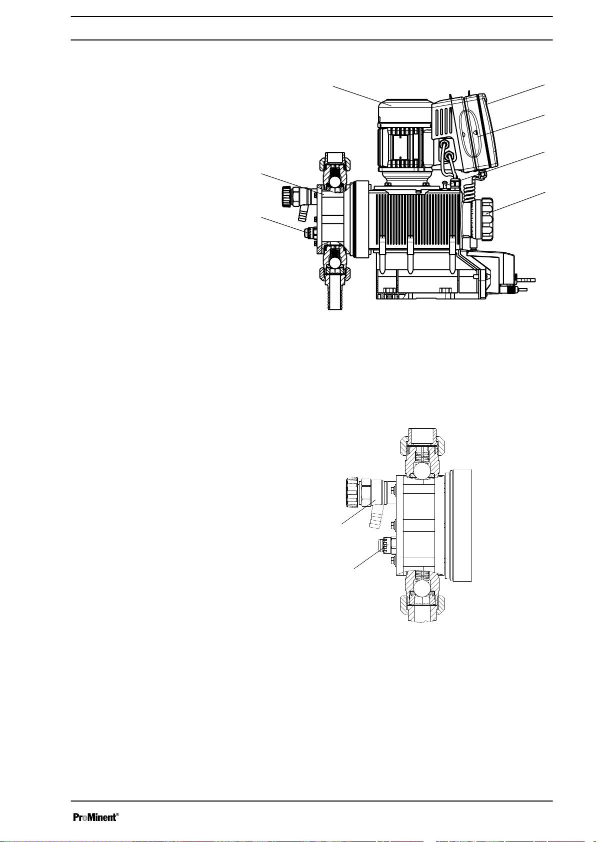
Fig. 2: Overview of equipment S2Cb
1 HMI control unit
2 Frequency converter
3 Drive unit
4 Stroke length adjustment wheel
5 Drive motor
6 Liquid end
7 Diaphragm rupture sensor
Fig. 3: Sigma control elements
1 Bleed valve or relief valve (dependent on identity code)
2 Diaphragm rupture sensor (visual)
13
Page 14
2
1
5
10
8
9
6
7
3
4
P_SI_0105_SW
P_SI_0106_SW_2
6
7
543
2
1
8
Overview of equipment and control elements
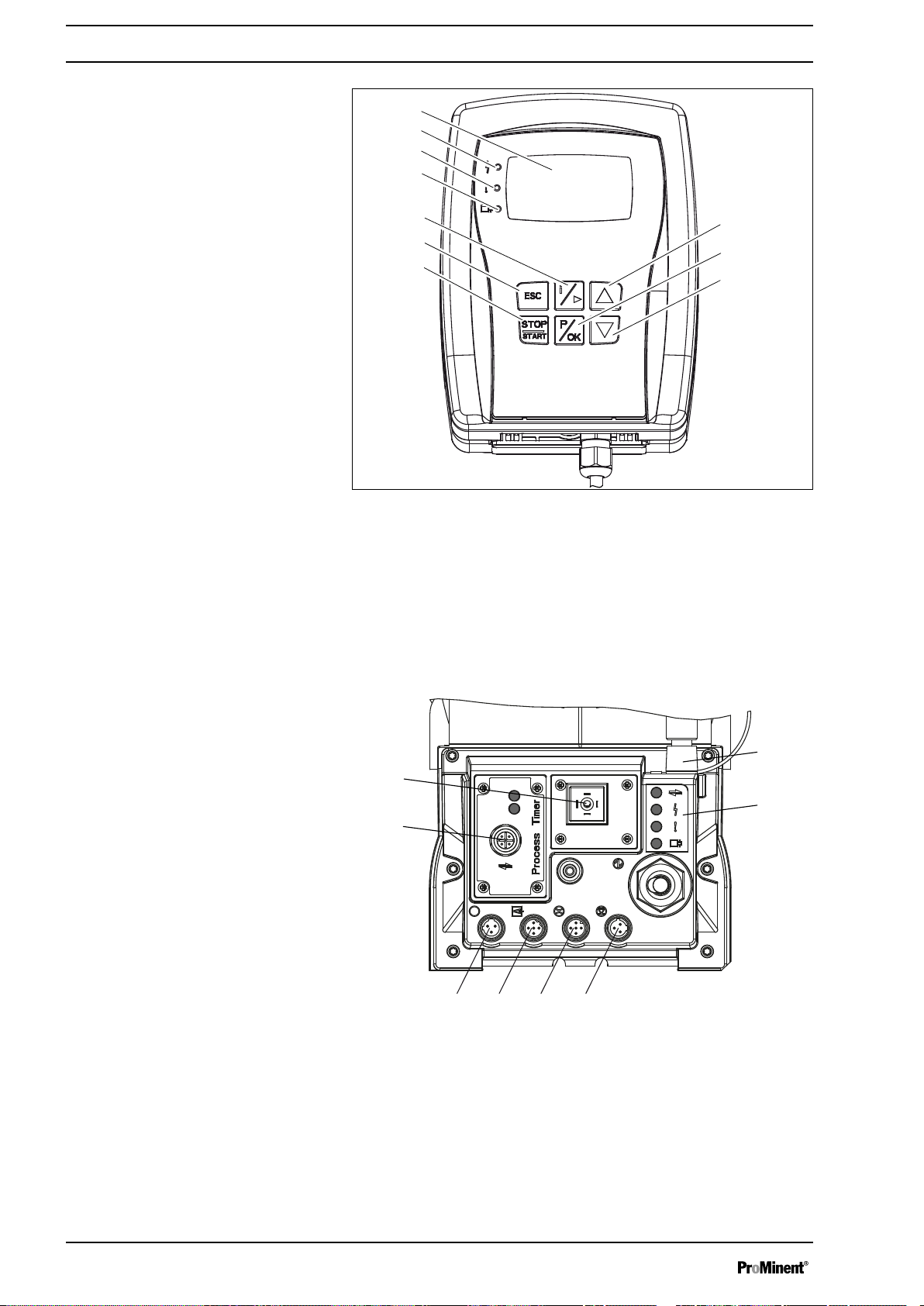
Fig. 4: HMI control elements
1 LCD screen
2 Fault indicator (red)
3 Warning indicator (yellow)
4 Operating indicator (green)
5
[i]
key / Cursor to right
6
[ESC]
7
8
9
10
key
[START/STOP]
[DOWN]
[P / OK]
[UP]
key
key
key
key
Fig. 5: Connector cover control elements
1 Relay and mA-output (option)
2
3 "Diaphragm rupture" terminal
4 "External control" terminal
5 "Dosing monitor" terminal
6 "Level Switch" terminal
7 "CAN-bus" port (external)
8 LEDs (as Fig. 4) and status LED CAN bus (external)
not shown Stroke length adjustment wheel
Optional module slot (timer, PROFIBUS®)
14
Page 15
10548
Manual
180
/min
Stop
Aux
B0412
Overview of equipment and control elements
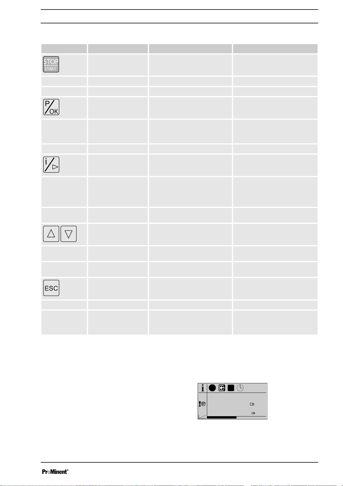
4.1 Key functions
Key Application In continuous displays (operation) In adjustment mode (set up)
[STOP/START]
start pump start pump
[P / OK]
Pressed for 2 s Change to adjustment mode -
[ i / >]
1x long press Change from the continuous dis‐
Pressed briefly Stop pump, Stop pump,
Pressed briefly Start batch (only in
ating mode),
Acknowledge errors
1x short press Change between the continuous
displays
Change between the secondary
displays
plays to the secondary displays
„Batch“
oper‐
Confirm entry - jump to next menu
option or to continuous display
Change between "Changing indi‐
vidual numbers" and "Changing a
number"
Change to the next digit
[UP], [DOWN]
Simultaneous long
[ESC]
Pressed for 2s - Jumps to a continuous display
Pressed briefly Change directly changeable varia‐
bles
Priming -
press
Pressed briefly - Jumps back one menu level
Select another setting, change
individual number or number.
Exit the setting menu without
saving
4.2 LCD screen identifiers
The LCD screen supports the operation and adjustment of the pump using
different identifiers:
The identifiers and information in the various fields of the LCD screen
have different meanings:
15
Page 16
1 2 3 4 5
6
9
10
7
8
B0413
Overview of equipment and control elements
1 Operating main display
2 Source indicator for stop
3 Auxiliary operation / Diaphragm break sensor deactivated
4 Module option
5 Mode
6 Main display
7 Secondary display
8 Display type (number of pages)
9 Other identifiers, error source indicator
10 Continuous display identifier (" i " as "Info")
The identifiers have the following meanings:
Field no. Icon Name Meaning
1 Stop The pump is stopped. Cause see field 2.
1 Priming The pump is currently priming (both
2
2
2
2 CAN
open
2 Profi
bus
3 Auxiliary The pump is currently pumping with the auxiliary fre‐
3
Manual The pump was stopped manually.
External signal The pump was externally stopped by the Pause contact.
Timer The pump was stopped via the timer.
CANopen The pump was stopped via the external CAN bus.
PROFIBUS
Diaphragm rupture A diaphragm rupture sensor is connected, but deacti‐
®
pressed).
The pump was externally stopped by the PROFIBUS®.
quency as the stroke rate.
During this time, the pump is in
mode.
vated.
[arrow keys]
„Manual“
operating
4 Timer The "Timer" option is active.
4 CAN
4 Profi
CANopen The "CANopen" option is active.
open
PROFIBUS
bus
®
The "PROFIBUS®" option is active.
16
Page 17
mm
0..200..20
4..204..20
Overview of equipment and control elements
Field no. Icon Name Meaning
5 MANUAL
5 CONTACT
5 BATCH
5 ANALOG
9
9 Stroke length adjust‐
9 Flow control A flow control is connected.
9
9
9
9
„Manual“ „Manual“
„Contact“ „Contact“
„Batch“ „Batch“
„Analog“ „Analog“
Error A fault exists.
ment
Memory The pump is in operating mode
0...20 mA The pump is in operating mode
4...20 mA The pump is in operating mode
Linear The pump is in operating mode
Deviation in the stroke length from the value set at the
time of the last locking of the setting menu.
the auxiliary function "Memory" is set.
cessing type
cessing type
The processing type
operating mode
operating mode
operating mode
operating mode
„0...20“
„4...20“
is set.
is set.
„Curve“-„Linear“
„Contact“
„Analog“
„Analog“
„Analog“
is set.
or
„Batch“
. The pro‐
. The pro‐
.
and
9 Upper sideband The pump is in operating mode
The processing type
9
10
10 Security Security lock (if a code was set).
Lower sideband The pump is in operating mode
Continuous display A continuous display appears on the LCD screen.
cessing type
For identifiers which appear in response to errors, see
the "Troubleshooting" chapter.
„Curve“-„Lower sideband“
„Curve“-„Upper sideband“
„Analog“
„Analog“
.
is set.
. The pro‐
is set.
17
Page 18
0
s s
a)
180 360 0
b)
180 360
ω ω
P_PL_0009_SW
P_SI_0120_SW
s
t
P_SI_0103_SW
s
t
Functional Description
5 Functional Description
Pump
5.1
The metering pump is an oscillating diaphragm pump, the stroke length of
which can be adjusted. An electric motor drives the pump. The slide rod
transmits the stoke motion to the diaphragms.
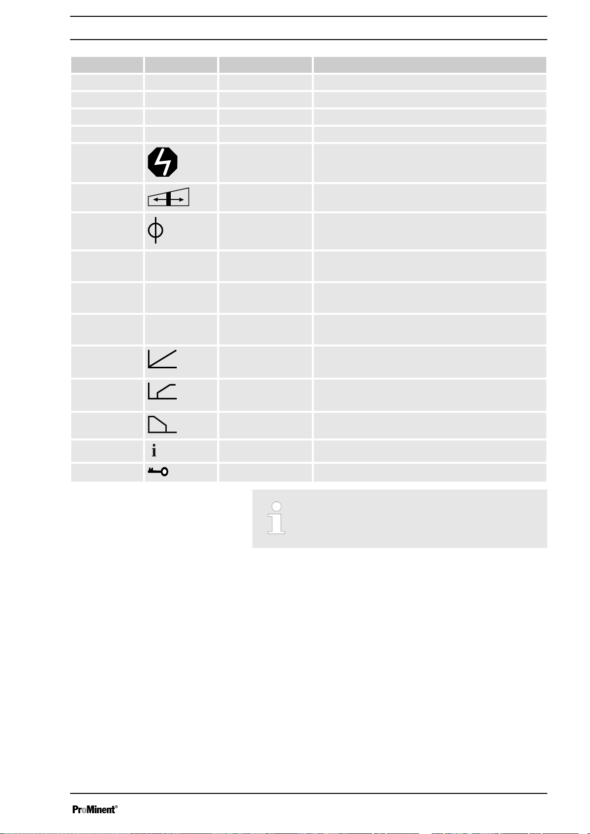
Illustration of the stroke movement
The stroke movement of the displacement body is continuously measured
and regulated so that the stroke is executed according to a previously set
dosing profile, see chapter
„Metering“ „setting“
.
The following dosing profiles are available:
n Normal
n Discharge opti.
n Suction opti.
Every metering profile is ineffective below the switchover frequency for Start/Stop mode.
Normal
Fig. 6: Stroke movement at a) maximum stroke length and b) reduced
stroke length.
s Stroke velocity
⍵ Cam rotational angle
+ Discharge stroke
- Suction stroke
Discharge opti.
With a discharge optimised dosing profile, the discharge stroke is elon‐
gated, the suction stroke is executed as quickly as possible. This setting is
for example suitable for those applications that require optimum mixing
ratios and as continuous as possible chemical mixing.
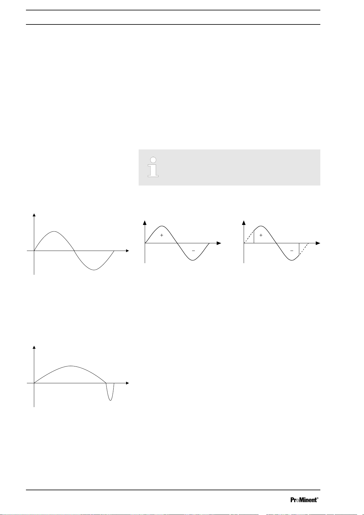
Suction opti.
18
Page 19
5.2
4
2
1
5
3
13
P_SI_0104_SW
s
t
Functional Description
With a suction optimised dosing profile, the suction stroke is elongated as
much as possible, which makes possible a precise and problem-free
dosing of viscous and gaseous media. Select this setting to minimise the
NPSH value as well.
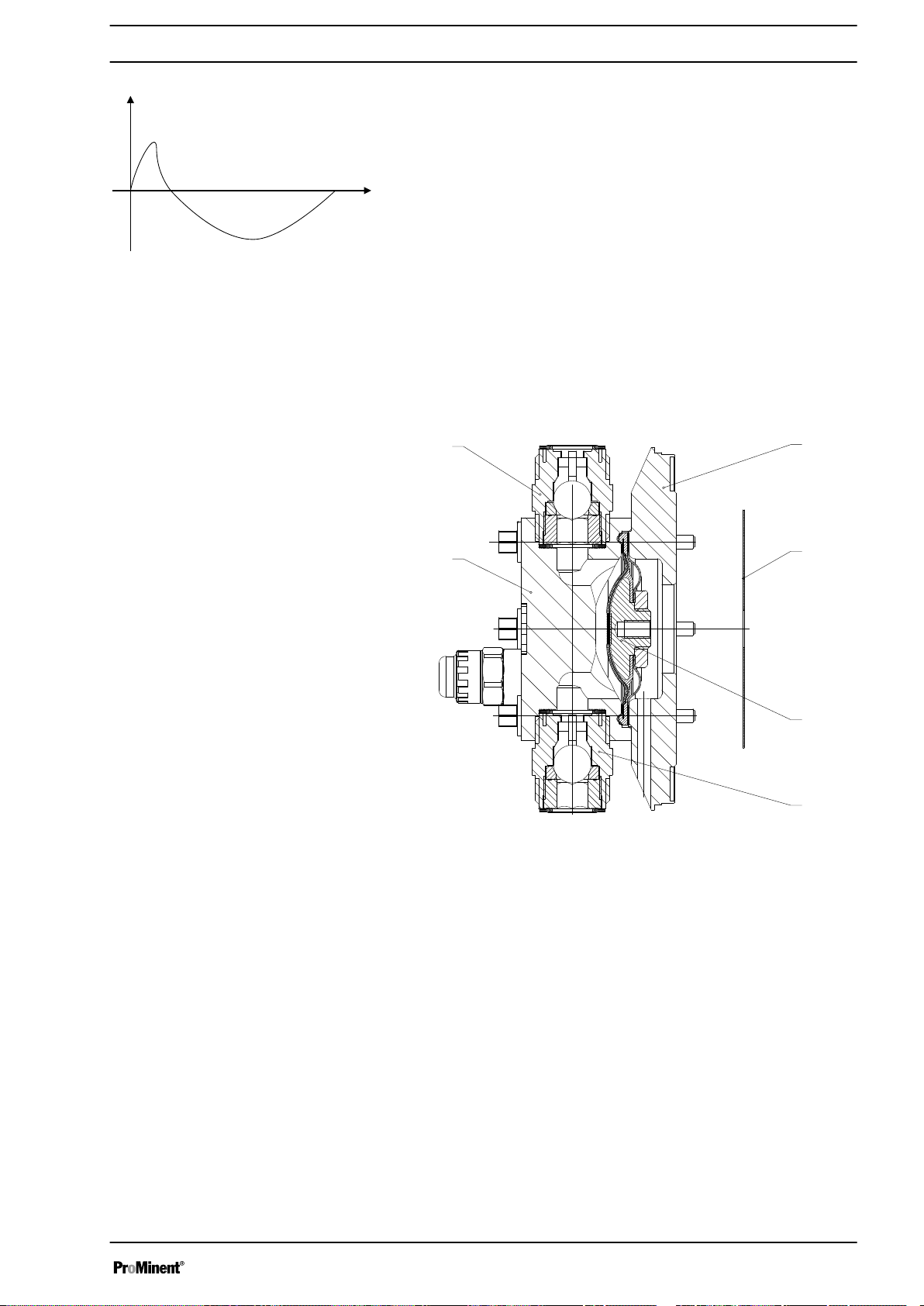
Liquid end
The diaphragm (2) hermetically shuts off the pump volume of the dosing
head (4) towards the outside. The suction valve (1) closes as soon as the
diaphragm (2) is moved in to the dosing head (4) and the feed chemical
flows through the discharge valve (3) out of the dosing head. The dis‐
charge valve (3) closes as soon as the diaphragm (2) is moved in the
opposite direction due to the vacuum pressure in the dosing head and
fresh feed chemical flows through the suction valve (1) into the dosing
head. One cycle is thus completed.
Fig. 7: Cross-section through the liquid end
1 Suction valve
2 Diaphragm
3 Discharge valve
4 Dosing head
5 Backplate
13 Safety diaphragm
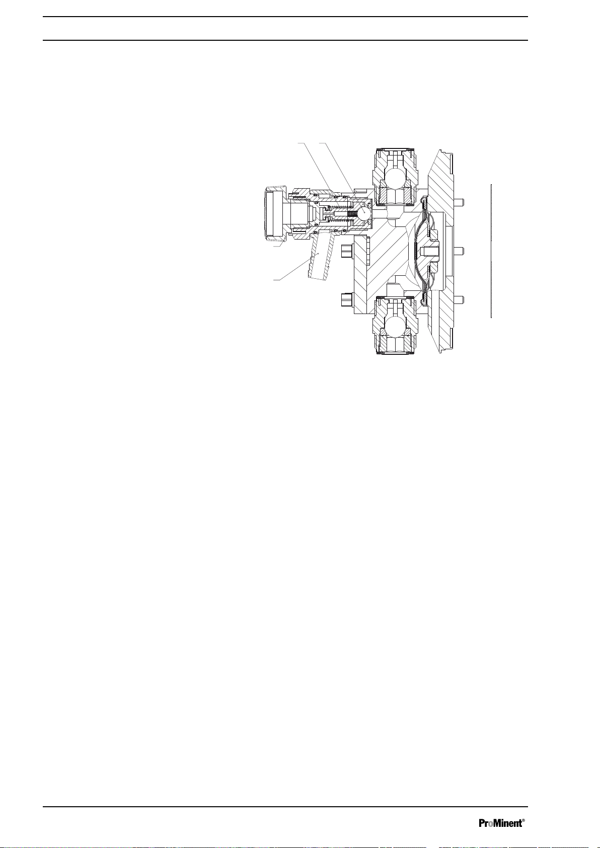
5.3 Bleed valve and integrated relief valve
Bleed valve
Integral relief valve
Turning the rotary dial (3) on the bleed valve to "open" causes it to open
and the liquid end can be bled. Or it is used as a priming aid for priming
against pressure. The feed chemical flows out through the hose connec‐
tion (5), e.g. into a storage tank.
The integral relief valve operates in the "close" position as a simple,
directly controlled relief valve. As soon as the pressure exceeds the pres‐
sure value, which is preset using the large spring (1), it lifts the ball (2).
The feed chemical flows out through the hose connection (5), e.g. into a
storage tank.
19
Page 20
1 2
5
3
P_SI_0109
Functional Description
The integral relief valve can only protect the motor and the gear, and then
only against impermissible positive pressure that is caused by the
metering pump itself. It cannot protect the system against positive pres‐
sure.
The integral relief valve works as a bleed valve as soon as the rotary dial
(3) is turned to "open": The valve opens and the liquid end can be bled. Or
it is used as a priming aid for priming against pressure.
5.4 Multi-layer safety diaphragm
Fig. 8: Relief valve and integrated relief valve
1 Spring, large
2 Ball
3 Rotary dial
5 Hose connection
With the visual diaphragm rupture sensor, the lowered red cylinder (6)
springs forward beneath the transparent cover (7) so that it then becomes
clearly visible
Fig. 9.
With the electrical diaphragm rupture sensor, a switch is switched. A con‐
nected signalling device must signal the diaphragm rupture.
Fig. 9: Visual diaphragm rupture sensor, triggered and untriggered
The electrical diaphragm rupture sensor is connected to the "diaphragm
rupture indicator" terminal. If a diaphragm ruptures, the red LED "Fault"
display lights up on the pump and the identifier "Error" and
„dia“
flash on
the LCD screen.
5.5 Operating modes
The operating modes are selected via the
„Mode“
the identity code, some operating modes may not be present):
20
menu (dependent on
Page 21

Functional Description
„Analog“
current signal via the "External control" terminal The processing of the cur‐
rent signal can be preselected via the control unit.
operating mode The stroke rate is controlled using an analog
„Manual“
unit.
„Contact“
making fine adjustments using small scaling or transfer factors. Metering
can be triggered either by a pulse received via the "External control" ter‐
minal or through a contact or a semiconductor switching element. A
metering quantity (batch) or a number of strokes (scaling or transfer factor
0.01 to 100.00) can be pre-selected via the control unit using the
„Factor“
„Batch“
working with large transfer factors (up to 99,999). The metering can be
triggered either by pressing the
"External control" terminal or through a contact or a semiconductor
switching element. It is possible to pre-select a metering quantity (batch)
or a number of strokes via the control unit.
„BUS“
FIBUS® DP interface). This operating mode provides the option of control‐
ling the pump via BUS (see “Supplementary instructions for ProMinent
delta and Sigma with PROFIBUS®".
operating mode The stroke rate is set manually via the control
operating mode: This operating mode provides the option of
setting.
operating mode: This operating mode provides the option of
[P]
key or by a pulse received via the
operating mode (Identity code, control variant: CANopen or PRO‐
5.6 Functions
The following function can be ordered via the identity code:
Booster pump (optional): The pump can issue an electronic warning and
switch off if a tolerance range is exceeded. The overload switch-off is to
protect the pump, not the system. In the event of overloading, the pump
signals an error via the LED displays, the LCD screen (
„blockade“
The following functions can be selected using the
"Calibrate" function: The pump can also be operated in the calibrated state
in all operating modes. In this case, the corresponding continuous displays
can then indicate the metering volume or the capacity directly. Calibration
is maintained throughout the stroke rate range. The calibration is also
maintained when the stroke length is altered by up to ±10% scale divi‐
sions.
"Auxiliary frequency" function: Enables a freely selectable and program‐
mable stroke rate to be switched on in the
controlled via the "external control" terminal. This auxiliary frequency has
priority over the operating mode stroke rate settings.
) and - if fitted – the fault indicating relay.
„Settings“
„p+“
or
„Settings“
menu:
menu, which can be
"Flow" function: Stops the pump when the flow is insufficient, provided a
dosing monitor is connected. The number of defective strokes, after which
the pump is switched off, can be set in the
The following functions are available as standard:
21
„Settings“
menu.
Page 22

Functional Description
"Level switch" function: Information about the liquid/powder level in the
chemical feed container is reported to the pump control. To do so, a twostage level switch must be fitted; it is connected to the "Level switch" ter‐
minal.
5.7 Options
Relay option
"Pause" function:
Control" terminal. The "Pause" function only works via the "External Con‐
trol" terminal.
The following functions are triggered by a key press:
"Stop" function: The pump can be stopped without disconnecting it from
the mains/power supply by pressing the
"Priming" function: Priming (short-term transport at maximum frequency)
can be triggered by simultaneous pressing of the two arrow keys.
The pump has several connection possibilities for the following options:
"Output relay" option: In the event of fault signals, warning signals, stop‐
ping of the pump or tripped level switches, the relay connects to complete
an electric circuit (for alarm horns etc.).
The relay can be retrofitted via a knock-out in the drive unit.
The various functions can be adjusted, see "Settings" - "Relay".
The pump can be remotely stopped via the "External
[STOP/START]
key.
Option "0/4-20 mA analog current output
and fault indicating relay"
5.8
Function and fault indicator
"Fault indicating and semiconductor relay" option In the event of fault sig‐
nals, warning signals, stopping of the pump or tripped level switches, the
fault indicating relay connects to complete an electric circuit (for control
panel etc.).
In addition to the fault indicating relay, the pacing relay can be used to
make a contact every stroke.
Other functions can be adjusted, see "Settings" - "Relay". The option can
be retrofitted via a knock-out in the drive unit.
The current output I signal indicates the pump's actual calculated metering
volume.
The option "0/4-20 mA analog current output and fault indicating relay" can
be retrofitted via a knock-out in the control unit.
Additionally the option always provides a semiconductor relay, see above.
Other functions can be adjusted, see "Settings" - "Relay".
The operating and fault statuses are indicated by the three LED indicators
and the
shooting" chapter.
„Error“
identifier on the LCD screen, see also the "Trouble‐
22
Page 23

5.9 LCD screen
5.10 LED Displays
Functional Description
„Error“
If a fault occurs, the identifier
sage.
CANopen status display (green): The CANopen status indicator shows the
status of the CANopen bus.
appears and an additional error mes‐
Colour Flash code Cause Conse‐
green illuminated Bus status
OPERA‐
TIONAL
green flashing Bus status
PREOPERA‐
TIONAL
red any Bus error no meas‐
Contact customer service in the event of all other flash codes.
Fault indicator (red): The fault indicator illuminates if a fault occurs e.g.
liquid level low 2nd stage".
Warning indicator (yellow): The warning indicator illuminates if the pump
electronics detect a condition which may lead to a fault, e.g. "liquid level
low 1st stage".
Operating indicator (green):
the pump is correctly connected to the operating voltage. The operating
indicator goes out briefly with every stroke.
The operating indicator illuminates provided
quence
Normal bus
mode
currently no
measured
value com‐
munication
ured value
transmission
Remedy
-
wait briefly.
Disconnect
HMI then
reconnect
Check
whether the
CAN con‐
nection is
faulty.
Notify
Service
5.11 Hierarchy of operating modes, functions and fault statuses
The different operating modes, functions and fault statuses have a dif‐
ferent effect on if and how the pump reacts.
The following list shows the order:
1. - Priming
2. - Fault, Stop, Pause
3. - Auxiliary frequency (external frequency changeover)
4. - Manual, external contact, batch, external analog
Comments:
re 1 - "Priming" can take place in any mode of the pump (providing it is
functioning).
re 2 - "Fault", "Stop" and "Pause" stop everything apart from "Priming".
re 3 - The "Auxiliary frequency" stroke rate always has priority over the
stroke rate specified by an operating mode listed under 4.
23
Page 24
h
P_MOZ_0016_SW
A
A
P_MOZ_0018_SW
Assembly
6 Assembly
Base
Refer to the correct dimensional drawings on our web‐
site www.prominent.com for assistance.
Compare the dimensions on the dimension sheet with
those of the pump.
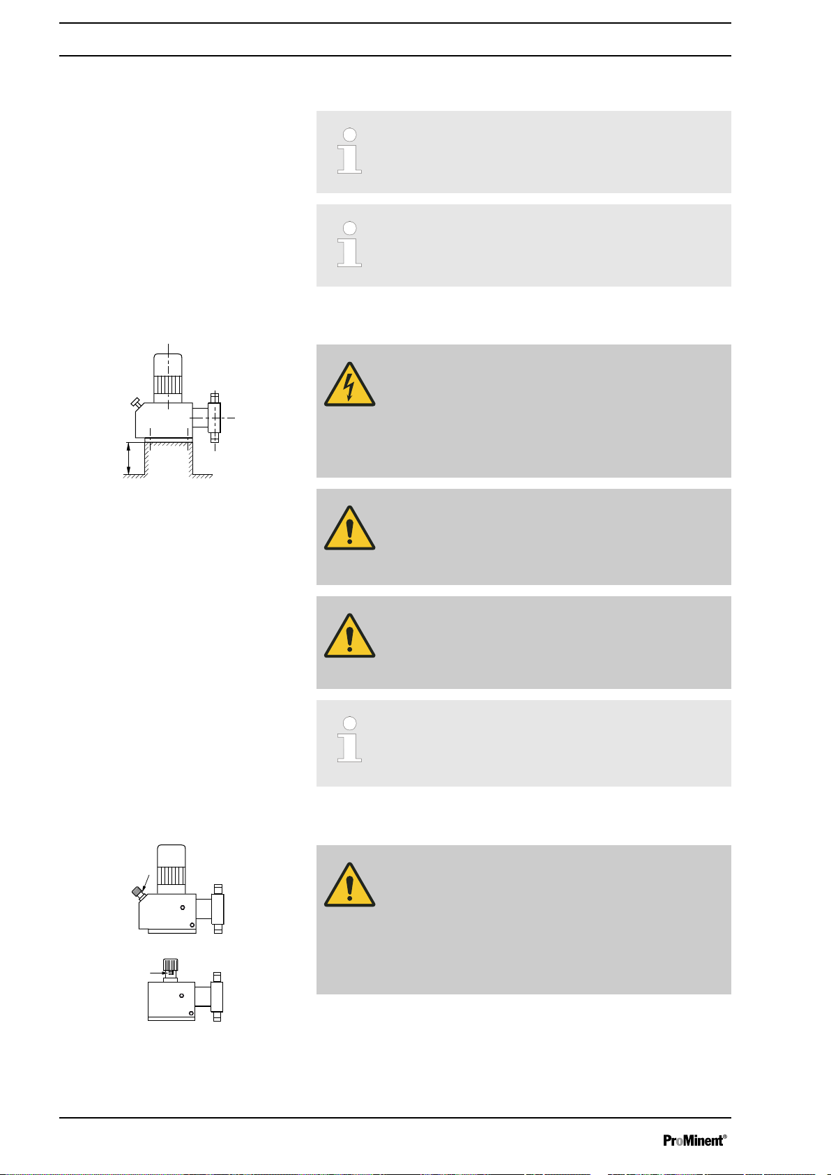
WARNING!
Danger of electric shock
If water or other electrically conducting liquids penetrate
into the drive housing, in any other manner than via the
pump's suction connection, an electric shock may occur.
– Position the pump so that it cannot be flooded.
Fig. 10
Space requirement
WARNING!
The pump can break through the base or slide off it
– Ensure that the base is horizontal, flat and perma‐
nently load-bearing.
CAUTION!
If your Sigma S2Cb is to be installed in place of a Sigma
S2Ca, a base plate order no. 1044841 is possibly
needed to lift the liquid end.
Capacity too low
Vibrations can disturb the liquid end valves.
–
Do not allow the base to vibrate.
CAUTION!
Danger from incorrectly operated or inadequately main‐
tained pumps
Danger can arise from a poorly accessible pump due to
incorrect operation and poor maintenance.
– Ensure that the pump is accessible at all times.
–
Adhere to the maintenance intervals.
Fig. 11
Position the pump so that control elements, such as the stroke length
adjustment knob, the indicating dial A or the oil inspection window, are
accessible.
In so doing, ensure there is enough space to carry out an oil change (vent
screws, oil drain plugs, oil trough ...).
24
Page 25

1
3
2
f
f
f
P_MOZ_0017_SW
Fig. 12
DNm
m
P_MOZ_0015_SW
Liquid end alignment
Assembly
If the HMI is mounted remotely from the pump: a clearly marked Stop
mechanism must be installed in the direct vicinity of the pump for emer‐
gencies!
1 Discharge valve
2 Dosing head
3 Suction valve
Ensure there is sufficient free space (f) around the dosing head as well as
the suction and discharge valve so that maintenance and repair work can
be carried out on these components.
Capacity too low
The liquid end valves cannot close correctly if they are
not upright.
–
Ensure that the discharge valve is upright.
Fastening
Fig. 13
Capacity too low
Vibrations can disturb the liquid end valves.
–
Secure the metering pump so that no vibrations can
occur.
Take the dimensions (m) for the fastening holes from the appropriate
dimensions- or data sheets.
Use appropriate bolts to fix the pump base to the supporting floor.
Mounting the HMI user control
If ordered with the wall mounting, the HMI can be mounted directly on a
wall.
Install the HMI in the immediate vicinity of the pump. If not provided for, fit
a circuit breaker there - refer to the "Installation, electrical" chapter. Ensure
that the system is arranged ergonomically.
When doing so, consider the available cable length.
Prevent tripping hazards.
Refer to the relevant dimensional drawing for the dimensions of the HMI
and fixing holes.
CAUTION!
Warning of faulty operation
– Do not install the HMI and cable too close to devices
and cabling that emit strong electrical interference.
25
Page 26
Installation
7 Installation
7.1 Installation, hydraulic
CAUTION!
Danger of injury to personnel and material damage
The disregard of technical data during installation may
lead to personal injuries or damage to property.
– Observe the technical data- refer to chapter "Tech‐
nical Data" and, where applicable, the operating
instructions of the accessories.
WARNING!
Danger of fire with flammable feed chemicals
– Only metering pumps with the identity code option
"Multi-layer safety diaphragm with rupture signalling
with electrical signal" are permitted to meter flam‐
mable media, with back pressures over 2 bar and if
the operator takes appropriate safety precautions.
WARNING!
Warning of feed chemical reactions to water
Feed chemicals that should not come into contact with
water may react to residual water in the liquid end that
may originate from works testing.
– Blow the liquid end dry with compressed air through
the suction connector.
–
Then flush the liquid end with a suitable medium
through the suction connector.
WARNING!
The following measures are an advantage when working
with highly aggressive or hazardous feed chemicals:
– Install a bleed valve with recirculation in the storage
tank.
Install an additional shut-off valve on the discharge
–
or suction ends.
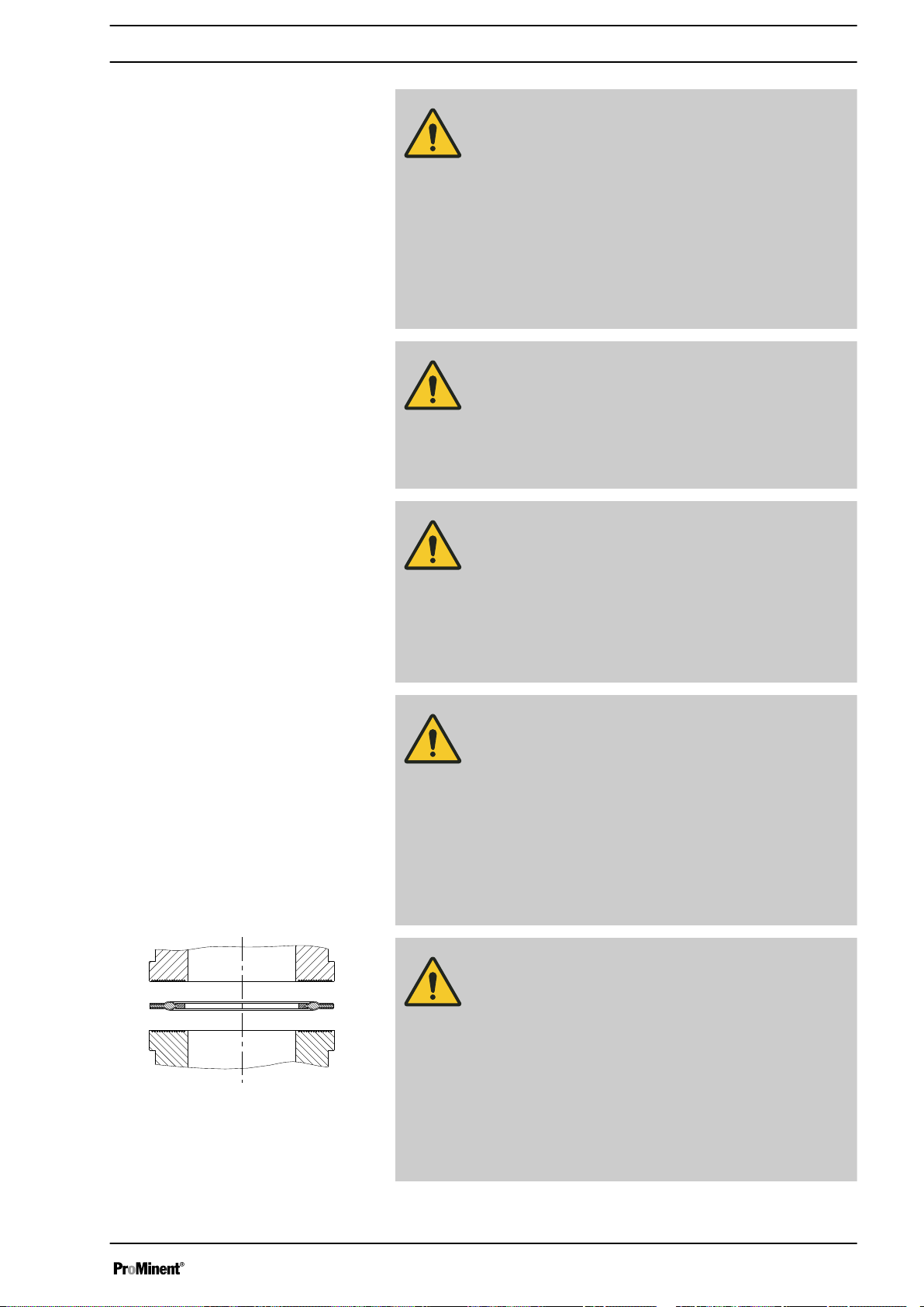
CAUTION!
Warning of feed chemical spraying around
PTFE seals, which have already been used / com‐
pressed, can no longer reliably seal a hydraulic connec‐
tion.
– New, unused PTFE seals must always be used.
CAUTION!
Suction problems are possible
The valves may no longer close properly with feed
chemicals with a particle size of greater than 0.3 mm.
– Install a suitable filter in the suction line.
26
Page 27
P_SI_0021
Installation
CAUTION!
Warning of the discharge line rupturing
With a closed discharge line (e.g. from a clogged dis‐
charge line or by closing a valve), the pressure that the
metering pump generates can reach several times more
than the permissible pressure of the system or the
metering pump. This could lead to lines bursting
resulting in dangerous consequences with aggressive or
hazardous feed chemicals.
– Install a relief valve that limits the pressure of the
pump to the maximum permissible operating pres‐
sure of the system.
CAUTION!
Warning against bursting of the suction or discharge
lines
Hose lines with insufficient pressure rating may burst.
– Only use hose lines with the required pressure
rating.
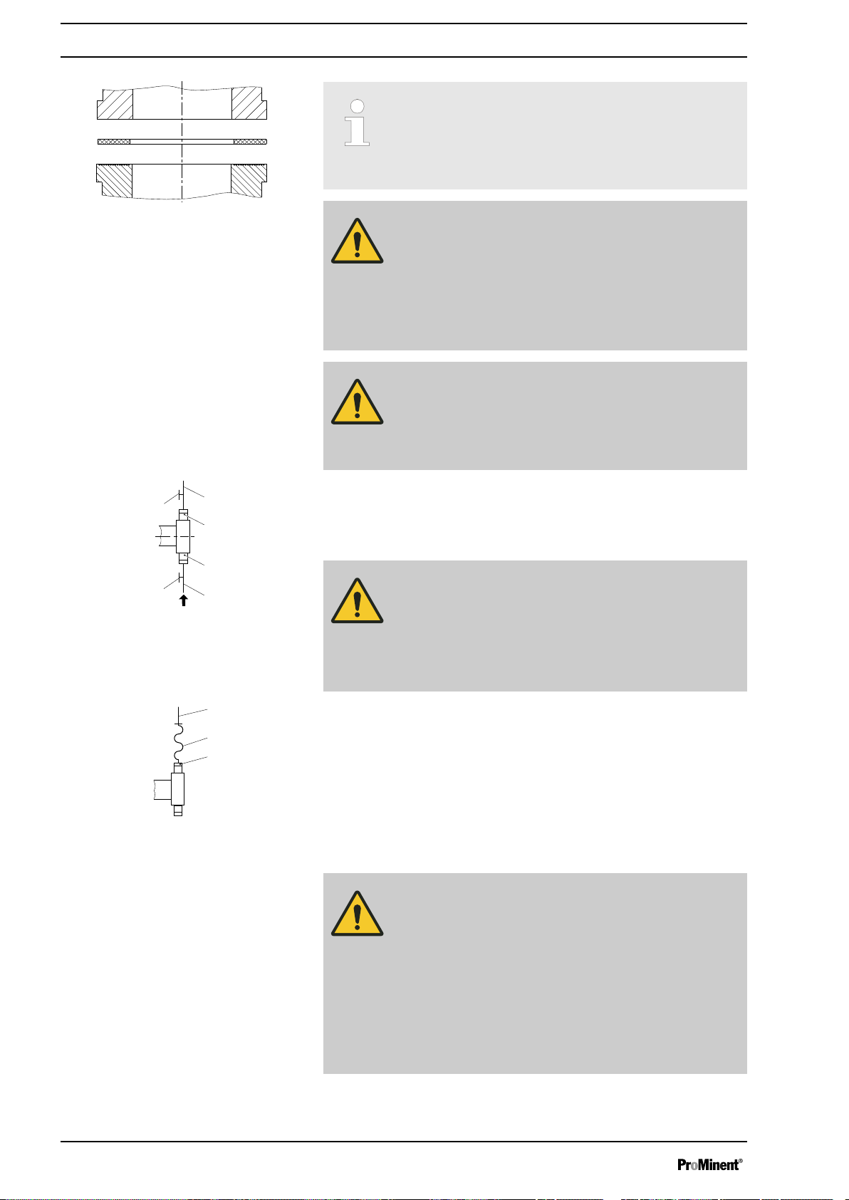
Fig. 14: Moulded composite seals with
corrugated insert
CAUTION!
Uncontrolled flow of feed chemical
Feed chemical can press through the metering pump in
an uncontrolled manner in the event of excessive pri‐
ming pressure on the suction side of the metering pump.
– Do not exceed the maximum permissible priming
pressure for the metering pump.
–
Set up the installation properly.
CAUTION!
Warning about lines coming loose
If suction, discharge and relief lines are installed incor‐
rectly, they can loosen / disconnect from the pump con‐
nection.
– Only use original hoses with the specified hose
diameter and wall thickness.
Only use clamp rings and hose nozzles that fit the
–
respective hose diameter.
– Always connect the lines without mechanical ten‐
sion.
CAUTION!
Warning against leaks
Leaks can occur on the pump connection depending on
the insert used.
– The pump is supplied with PTFE moulded compo‐
site seals with a flare, which are used for the pump
connections. They seal the connections between
grooved pump valves and the grooved inserts from
ProMinent - see
Ä Further information on page 26
– In the event that an unflared insert is used (e.g. third
party part), an elastomer flat seal must be used see
Ä Further information on page 26
.
.
27
Page 28
P_SI_0022
1
1
2
3
4
5
P_MOZ_0020_SW
1
2
3
P_MOZ_0021_SW
Installation
Precise metering is only possible when the back
–
pressure is maintained above 1 bar at all times.
–
If metering at atmospheric pressure, a back pres‐
sure valve should be used to create a back pressure
of approx. 1.5 bar.
Fig. 15: Elastomer flat seal for a smooth
insert
Fig. 16: Manometer connecting options
CAUTION!
Warning of backflow
A back pressure valve, spring-loaded injection valve,
relief valve, foot valve or a liquid end do not represent
absolutely leak-tight closing elements.
– Use a shut-off valve, a solenoid valve or a vacuum
breaker for this purpose.
CAUTION!
To check the pressure conditions in the piping system it
is recommended that connecting options are provided
for a manometer close to the suction and pressure con‐
nector.
1 Manometer socket
2 Discharge line (pipe)
3 Discharge valve
4 Suction valve
5 Suction line (pipe)
CAUTION!
Connect the pipelines to the pump so that no residual
forces act on the pump, e.g. due to the offsetting, weight
or expansion of the line.
Only connect steel or stainless steel piping via a flexible
piping section to a plastic liquid end.
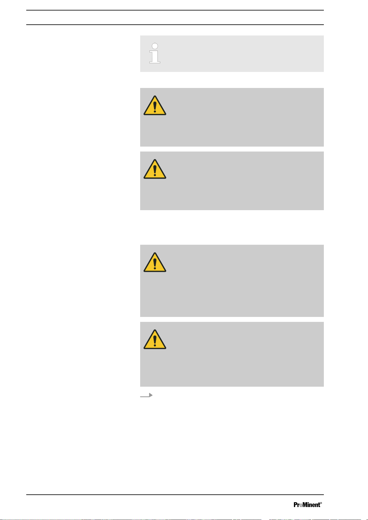
Fig. 17: Steel pipeline at the liquid end
Integral relief valve or integral bleeder
valve
1 Steel piping
2 Flexible pipe section
3 Plastic liquid end
WARNING!
Product can be dangerously contaminated
Only with the design "Physiologically safety with regard
to wetted materials".
If the integral bleed valve or the integral relief valve
opens, the feed chemical comes into contact with phys‐
iologically harmful seals.
– Do not route feed chemical that escapes from the
integral bleed valve or the integral relief valve back
into the process.
28
Page 29
P_SI_0023
Installation
CAUTION!
Danger due to incorrect use of the integral relief valve
The integral relief valve can only protect the motor and
the gear, and then only against impermissible positive
pressure that is caused by the metering pump itself. It
cannot protect the system against positive pressure.
– Protect the motor and gear of the system against
positive pressure using other mechanisms.
Protect the system against illegal positive pressure
–
using other mechanisms.
CAUTION!
Warning of feed chemical spraying around
If no overflow line is connected to the integral relief valve
or the integral bleeder valve, feed chemical will spray out
of the hose connector as soon as the relief valve opens.
– Always connect an overflow line to the integral relief
valve or the integral bleeder valve and feed it back
into the storage tank or - if required by the regula‐
tions - into a special storage tank.
CAUTION!
Danger of cracking
Cracking of the PVT liquid end can occur if a metal over‐
flow line is connected to the relief valve.
– Never connect a metal overflow line to the relief
valve.
CAUTION!
Danger of the integral relief valve failing
The integral relief valve no longer operates reliably with
feed chemicals having a viscosity of greater than 200
mPa s.
– Only use the integral relief valve with feed chemicals
having a viscosity up to 200 mPa s.
CAUTION!
Warning against leaks
Feed chemical, which remains in the overflow line at the
relief valve or bleeder valve, can attack the valve or
cause it to leak
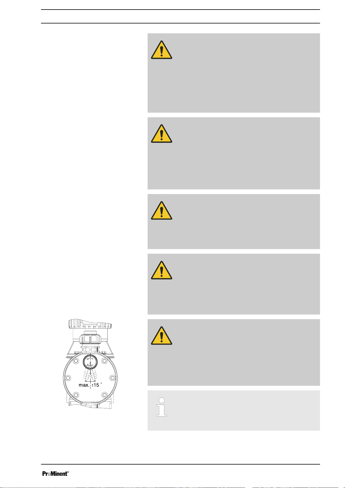
– Route the overflow line with a continuous slope and
moreover with the tube nozzle pointed downwards see .
Fig. 18: Permissible alignment of the relief
valve
If the overflow line is fed into the suction line, the bleed
function is blocked.
Therefore lead the overflow line back into the storage
tank.
29
Page 30
Installation
Diaphragm rupture sensor
When operating the integral relief valve close to the
opening pressure, a minimal overflow into the overflow
line can occur.
CAUTION!
Danger resulting from unnoticed diaphragm rupture
If the pump has been ordered with an electric diaphragm
rupture sensor, it still has to be installed.
– Screw the enclosed diaphragm rupture sensor into
the liquid end.
CAUTION!
Warning of unnoticed diaphragm rupture
Only above approximately 2 bar system back pressure is
a signal generated upon a diaphragm rupture.
– Only rely on the diaphragm rupture sensor at back
pressures greater than 2 bar.
7.1.1 Basic installation notes
Safety notes
CAUTION!
Danger resulting from rupturing hydraulic components
Hydraulic components can rupture if the maximum per‐
missible operating pressure is exceeded.
– Never allow the metering pump to run against a
closed shut-off device.
–
With metering pumps without integral relief valve:
Install a relief valve in the discharge line.
CAUTION!
Hazardous feed chemicals can escape
With hazardous feed chemicals: Hazardous feed chem‐
ical can leak out when using conventional bleeding pro‐
cedures with metering pumps.
– Install a bleed line with a return into the storage
tank.
Shorten the return line so that it does not dip into the feed chemical
in the storage tank.
30
Page 31

P_MOZ_0043_SW
2
1
A)
B)
*
PD
1
2
Fig. 19: (A) standard installation, (B) with pulsation damper
1 Main line
2 Storage tank
Installation
Legend for hydraulic diagram
Symbol Explanation Symbol Explanation
Metering pump Foot valve with filter meshes
Injection valve Level switch
Multifunctional valve Manometer
7.2 Installation, electrical
General safety notes
WARNING!
Danger of electric shock
Unprofessional installation may lead to electric shocks.
– Crimp cable end sleeves onto all shortened cable
cores.
–
Only allow technically trained personnel to under‐
take the electrical installation of the device.
WARNING!
Danger of electric shock
A mains voltage may exist inside the motor or electrical
ancillaries.
– If the housing of the motor or electrical ancillaries
has been damaged, you must disconnect it from the
mains immediately. Only return the pump to service
after an authorised repair.
CAUTION!
Use ProMinent cables to avoid unnecessary problems.
31
Page 32

Installation
What requires electrical installation?
What requires electrical installation?
n Level switch
n Diaphragm rupture sensor, electrical (option)
n Metering monitoring (option)
n Relay (option)
n External control
n mA Output (Optional)
n Bus connector (optional)
n Timer (option)
n Pump, power supply
7.2.1
Level switch, diaphragm rupture sensor
(option) and dosing monitor (option)
Control connectors
CAUTION!
Incoming signals can remain without effect
If the universal control wire, the external/pacing cable or
the level monitoring cable is shortened below 1.20 m,
the pump does not detect that it is connected. Conse‐
quently a warning message (for example) can be sup‐
pressed.
– Do not shorten this cable below 1.20 m.
Connect the plugs of the level switch, diaphragm rupture sensor and
dosing monitor to the corresponding sockets on the front side of the con‐
trol. In case of uncertainty - see chapter "Overview of equipment and con‐
trol elements"
CAUTION!
Danger resulting from unnoticed diaphragm rupture
All pumps ordered with an electric diaphragm rupture
sensor need to be electrically installed.
– Electrically connect the enclosed diaphragm rupture
sensor.
Only with flammable media:
WARNING!
Fire danger
The electric diaphragm rupture sensor must stop the
pump immediately after a diaphragm rupture and trigger
an alarm.
The pump must only be returned to service once a new
diaphragm has been fitted.
32
Page 33

7.2.1.1 Relay
2
3
1
4
P_SI_0111_SW
P_SI_0043
2
3
1
4
P_SI_0111_SW
7.2.1.1.1
Fault indicating relay 230 V
Fig. 20: Pump assignment
Installation
If another switching function is required, the pump can be reprogrammed
„Relay“
in the
The relay can be retrofitted and operates once it is plugged into the relay
board.
menu.
Fault indicating relay 230 V
Data Value Unit
Maximum contact load at 230 V and 50/60
Hz:
Minimum mechanical lifespan: 200,000 switching
Fault indicating relay 230 V
Pin assignment
To pin VDE cable Contact CSA cable
1 white NO (normally open) white
Fig. 21: Cable assignment
2 green NC (normally closed) red
4 brown C (common) black
7.2.1.1.2 Fault indicating and pacing relay option
The first switch is a relay. The pacing output is electrically-isolated by
means of an optocoupler with a semiconductor switch.
If another switching function is required, the pump can be reprogrammed
in the
The relay can be retrofitted and operates once it is plugged into the relay
board.
„Relay“
8 A (resis‐
tive)
operations
menu.
Fig. 22: Pump assignment
Fault indicating relay (24 V)
Pacing relay
Data Value Unit
Maximum contact load at 24 V and 50/60
100 mA
Hz:
Minimum mechanical lifespan: 200,000 switching
operations
Data Value Unit
Residual voltage max. at I
= 1 µA 0.4 V
off max
Maximum current 100 mA
33
Page 34

P_SI_0044
2
3
1
4
P_SI_0010_SW
Installation
Fault indicating and pacing relay option
Data Value Unit
Maximum voltage 24 VDC
Closing duration 100 ms
Pin assignment
To pin VDE cable Contact Relay
1 yellow NC (normally closed) or
Fig. 23: Cable assignment
4 green C (common) Fault indi‐
3 white NC (normally closed) or
2 brown C (common) Pacing relay
7.2.1.1.3 Current output and fault indicating / pacing relay (24 V)
The module can be retrofitted and operates once it is plugged into the
module board.
„ANALOG OUTPUT“
In the
rent output can be selected.
If another switching function is required, the relay can be reprogrammed in
the
„Relay“
menu.
Fig. 24: Pump assignment
Fault indi‐
NO (normally open)
cating relay
cating relay
Pacing relay
NO (normally open)
menu, the variable to be signalled by the cur‐
Current output
Fault indicating / pacing relay (24 V)
Data Value Unit
Open circuit voltage: 8 V
Current range: 4 ... 20 mA
Ripple, max.: 80 μA pp
Ripple, max.: 250 Ω
Data Value Unit
Residual voltage max. at I
= 1 µA 0.4 V
off max
Maximum current 100 mA
Maximum voltage 24 VDC
Closing duration 100 ms
34
Page 35

Current output and fault indicating / pacing
P_SI_0044
relay (24 V)
Installation
To pin VDE cable Contact Relay
Fig. 25: Cable assignment
1 yellow "+" Current
output
4 green "-" Current
output
3 white NC (normally closed) or
NO (normally open)
Fault indi‐
cating /
pacing relay
2 brown C (common) Fault indi‐
cating /
pacing relay
35
Page 36

Universal control wire connection diagramUniversal control wire connection diagram
Site endSite end
CableCable
Pump, insidePump, inside
2 white / Contact
4 brown / GND
GND
External
activation
Function "External Contact"
(ProMinent external/contact cable)
2-core
1 brown / Pause
2 white / Contact
4 black / GND
3 blue / Analog
5 grey /Auxiliary
GND
GND
External
activation
1 brown / Pause
2 white / Contact
4 black / GND
3 blue / Analog
5 grey /Auxiliary
External
activation
1 brown / Pause
2 white / Contact
4 black / GND
3 blue / Analog
5 grey /Auxiliary
External
activation
1 brown / Pause
2 white / Contact
4 black / GND
3 blue / Analog
5 grey /Auxiliary
External
activation
GND
GND
+
-
Function "External Contact"
(ProMinent universal control wire)
5-core
"Pause" function
"Auxiliary rate" function
Function "External Contact"
Pulse frequency,
e.g. contact water meter, PLC etc.
Pulse frequency,
e.g. contact water meter, PLC etc.
Continuous contact (potential-free)
E.g. external on/off of control panel
Continuous contact (potential-free)
e.g. of control panel
0/4-20 mA
Analog signal,
e.g. of magnetic inductive
Flow meter
P_SI_0091_SW
Installation
7.2.1.2 External control
External control
36
Page 37

Technical data "external control"
1
54
2
3
P_BE_0014_SW
Semi-conductor switch elements with a residual voltage of -0.7 V (e.g.
transistors in open-collector circuits) or contacts (relays) can be used as
input switch elements.
Pin
Installation
Pin 1 = Pause input (activating func‐
Voltage with open contacts: approx. 5 V
tion)
Input resistance: 10 kΩ
Control:
n Potential-free contact (approx. 0.5
mA)
n Semiconductor switch (residual
voltage < 0.7 V)
2 = contact input Voltage with open contacts: approx. 5 V
Input resistance: 10 kΩ
Control:
n Potential-free contact (approx. 0.5
mA)
n Semiconductor switch (residual
voltage < 0.7 V)
min. contact duration: 20 ms
Max. pulse frequency: 25 pulses/s
3 =Analog input Input apparent ohmic resistance approx. 120 Ω
4 = GND
5 = auxiliary input Voltage with open contacts: approx. 5 V
Input resistance: 10 kΩ
Control:
n Potential-free contact (approx. 0.5
mA)
n Semiconductor switch (residual
voltage < 0.7 V)
The metering pump makes its first metering stroke at approx. 0.4 mA (4.4
mA) and enters into continuous operation at approx. 19.2 mA.
37
Page 38

GND
Inputs Outputs
Pump, inside
Block diagram Sigma Control
External
activation
Diaphragm
rupture
sensor
Stroke
sensor
Level
sensor
Fault indicating
relay
Warning
Network
Wiring connection
examples:
next page
Stroke
sensor
Flow Control
Diaphragm
rupture
sensor
3 white / NO (pacing relay)
Fault indicating
and
Pacing
relay
VDE cable:
Empty signal
2 brown / C (pacing relay)
1 white / NO
4 brown / C
1 yellow / NO (fault alert)
4 green / C (fault alert)
2 green / NC (fault alert)
3 brown / Pause
2 blue / Alarm
1 black / GND
1 brown / 5 V
2 white / Cod.
4 black / GND
3 blue
2 blue / Alarm
1 black / GND
VDE cable:
1 brown / Pause
2 white / Contact
4 black / GND
3 blue / Analog
5 grey /Auxiliary
P_SI_0089_SW
Installation
Fig. 26: Block diagram Sigma Control
38
Page 39

Universal control wire connection diagramUniversal control wire connection diagram
Site endSite end
CableCable
Pump, insidePump, inside
2 white / Contact
4 brown / GND
GND
External
activation
Function "External Contact"
(ProMinent external/contact cable)
2-core
1 brown / Pause
2 white / Contact
4 black / GND
3 blue / Analog
5 grey /Auxiliary
GND
GND
External
activation
1 brown / Pause
2 white / Contact
4 black / GND
3 blue / Analog
5 grey /Auxiliary
External
activation
1 brown / Pause
2 white / Contact
4 black / GND
3 blue / Analog
5 grey /Auxiliary
External
activation
1 brown / Pause
2 white / Contact
4 black / GND
3 blue / Analog
5 grey /Auxiliary
External
activation
GND
GND
+
-
Function "External Contact"
(ProMinent universal control wire)
5-core
"Pause" function
"Auxiliary rate" function
Function "External Contact"
Pulse frequency,
e.g. contact water meter, PLC etc.
Pulse frequency,
e.g. contact water meter, PLC etc.
Continuous contact (potential-free)
E.g. external on/off of control panel
Continuous contact (potential-free)
e.g. of control panel
0/4-20 mA
Analog signal,
e.g. of magnetic inductive
Flow meter
P_SI_0091_SW
Installation
7.2.2 HMI operating unit
If the pump is operated via the HMI, the HMI must be connected to the
CAN port above the LEDs of the pump base.
39
Page 40

Installation
If the pump is operated without the HMI, the supplied sealing cap must be
plugged into the CAN port above the LEDs of the pump base.
CAUTION!
Risk of short circuit
If liquid penetrates into the CAN port, a short circuit may
occur in the pump.
– A CAN plug or the supplied sealing cap must always
be plugged into the CAN port.
CAUTION!
Danger of malfunctions
Incorrect operation via the CAN bus leads to malfunc‐
tions.
– When operating with the HMI connected, do not
connect any other control (e.g. DXCa) to the CAN
port.
7.2.3 Pump, power supply
WARNING!
Risk of electric shock
This pump is supplied with a grounding conductor and a
grounding-type attachment plug.
– To reduce the risk of electric shock, ensure that it is
connected only to a proper grounding-type recep‐
tacle.
WARNING!
Danger of electric shock
In the event of an electrical accident, it must be possible
to quickly disconnect the pump, and any electrical ancil‐
laries which may possibly be present, from the mains.
– Install an emergency cut-off switch in the mains
supply line to the pump and any electrical ancillaries
which may be present or
Integrate the pump and electrical ancillaries which
–
may be present in the emergency cut-off manage‐
ment of the system and inform personnel of the iso‐
lating option.
WARNING!
If the HMI cannot be operated directly from the pump
(specifically with versions with a cable longer than 2 m),
provide an option to disconnect the pump from the mains
power supply in the event of an emergency. Clearly
assign and label this option to the pump.
WARNING!
An on/off switch may not be fitted on the pump,
dependent on the identity code and installation.
40
Page 41

CAUTION!
Pump can be damaged
The pump can only be stopped when running via an:
– External cable
[Stop]
–
Use a relay or a contactor if the pump has to be defini‐
tively actuated via the mains cable. However, take into
account the pump’s starting current.
key.
To be able to switch off the pump (to a zero-volts state)
independently from the entire installation (e.g. for repair),
use an electrical isolating device in the mains supply
cable, e.g. a mains switch or a plug / socket combina‐
tion. Clearly identify this isolating device as such.
Install the pump cable. Use the original cable supplied!
Installation
7.2.4 Other units
Other units
–
Key electrical data can be found on the pump name‐
plate.
Install the other units according to their supplied documentation.
41
Page 42

Continuous
display
Auxiliary freq.
070 /min
Settings
Auxiliary freq.
Calibration
Dosing
Relay
Diaphragm break
= Adjustable
= Setting option
2 s 2 s
Setting
8 Setting
Please read the overviews in the appendix, "Control
–
elements and key functions" and "Operating/setting
diagram" for supplementary information.
–
If no key is pressed for a 1 minute duration, the
pump returns to a continuous display.
8.1 Basic Principles for Setting up the Control
Confirming an entry
Briefly press the
[P/OK]
key.
The display simultaneously changes to the next selection, to the next
menu option or into a continuous display.
Press
[ESC]
Quitting a menu option without confirming
it
Jumping back to a continuous display
Changing adjustable variables
You will jump back to the previous menu option or menu.
Press and hold the
Press the arrow keys
.
[ESC]
[UP]
In this way the digit between the triangles is increased or reduced.
Select the digit position in a number using the key
Confirming adjustable variables
Press the
[P/OK]
key.
The display simultaneously changes to the next selection, to the next
menu option or into a continuous display.
8.2 Checking adjustable values / error messages
Continuous displays
Before you adjust the pump, you can check the actual settings of the
adjustable variables:
1. Press the key
[i/>]
uous display (An "i" is visible at the top left).
Each press of the
ð
or a plain text error message.
2. The continuous display values can be changed using the
[arrow keys]
.
key for 2 seconds.
or
[DOWN]
.
[i/>]
.
("i" for "Info"), if the pump is displaying a contin‐
[i/>]
key displays another continuous display
42
Page 43

Setting
The number of continuous displays depends on the iden‐
tity code, the selected operating mode and the con‐
nected additional devices, see overview "Continuous
displays" in the appendix.
A horizontal scroll bar shows the number of continuous
displays and error messages and the position of the dis‐
played continuous display or error message.
With error messages an identifier appears while displays
with clear text appear between the continuous displays
(and an error code).
Secondary displays
8.3 Changing to set up mode
The lowest line in the information displays (2nd level continuous display)
shows different information, which cannot however be adjusted here, see
overview "Secondary displays" in the appendix.
If you are in a continuous display, you can access the bottom line of the
info displays by:
[i/>]
1. Keep key
bottom line.
2. Now quickly press the
the bottom line.
If the
[P/OK]
pump changes to adjustment mode.
If under
all“
was set (top left key symbol instead of "i"), proceed as follows:
1. Press the
2. Enter the password (
3. Confirm the display with the
key is pressed for 2 seconds in a continuous display, the
„Service è Safety è Access protection“ „Lock menu“
The
ð
The
ð
The
ð
pressed down until a small triangle appears in the
[i/>]
key to page through the info displays of
[P/OK]
key.
„Password“
„Password valid“
„Main menu“
display appears.
[Arrow keys]
appears.
!) and confirm with the
display appears.
[P/OK]
key.
or
„Lock
[P/OK]
key.
The following menus can be initially chosen in adjustment mode - see also
the overview "Operating/setting diagram":
n Menu
n Menu
n Menu
n Menu
n Menu
To adapt the pump to your process requirements, you must:
1. Select the operating mode in the
2. Carry out the adjustment for this operating mode under the
„Mode“
„Settings“
„Service“
„Information“
„Language“
„Mode“
menu.
„Settings“
menu.
43
Page 44

2 s
Continuous
display
Menu
Mode
Menu
Service
Menu
Settings
Menu
Information
1.
2.
Menu
Language
Main menu
Mode
Settings
Service
Information
Language
Continuous
display
Main menu
Mode
Settings
Service
Information
Language
Mode
Manual
Batch
Contact
Analog
Setting
8.4 Selecting the operating mode (Menu "Mode")
8.5 Operating mode settings (menu "Settings")
„Mode“
In the
menu (depending on the identity code, some operating
modes may not be present) the following operating modes can be
selected:
n
n
n
n
„Manual“
„Batch“
„Contact“
„Analog“
: for manual operation
: for batch operation
: for contact operation
: for current control
Various settings can be adjusted in the
selected operating mode.
„Settings“
menu dependent on the
Setting menus are available in all operating modes for the following pro‐
grammable functions:
n
„Auxiliary frequency“
n
„Calibration“
n
„Metering“
n
„Diaphragm rupture“
n
„System“
See also "Programmable function settings".
44
Page 45

Continuous
display
Menu
Set-upSet-up
Menu
Mode**
Menu
Timer*Timer*
Menu
Profibus*Profibus*
Menu
Auxiliary freq.Auxiliary freq.
Menu
Flow*Flow*
Menu
CalibrateCalibrate
Menu
DosingDosing
Menu
Relay*Relay*
Menu
Analog output*Analog output*
Menu
Diaphragm breakDiaphragm break
Menu
SystemSystem
Main menu
Mode
Set-up
Service
Information
Language
Setting
As to whether or not a further setting menu is available, depends on the
selected operating mode and the connected devices or modules.
Fig. 27: "Settings" menu branch
8.5.1 "Manual" operating mode settings
No setting menu is available in
„Settings“
8.5.2 "Batch" mode settings
The
„BATCH“
„Settings“
.
menu.
„Manual“
menu is available under
operating mode in the menu
„Batch“
mode in the
45
Page 46

Continuous
display
Memory
Off
On
Main menu
Mode
Settings
Service
Information
Language
Settings
Batch
Auxiliary freq.
Calibrate
Dosing
Relay
Batch
Memory
Factor
End
5
Factor
Batch
Memory
Factor
End
5 0 0 0 0 5
Setting
"Memory" function extension
The operating mode
„Batch“
is one variant of the
„Contact“
operating
mode - see the following chapter. Here also, you can select a number of
strokes (no fractions, only integers from 1 to 99,999).
Operating mode
Metering can be triggered by pressing the
„Batch“
is intended for large metering quantities.
[P/OK]
key or via a pulse
received via the "External Control" terminal.
The number of received pulses, which could not yet be processed, is
stored by the pump in the stroke memory, if it was activated.
CAUTION!
When changing over from the "Manual" operating mode
to the "Batch" operating mode, the pump maintains the
stroke rate.
The stroke rate can also be set in „Batch“ mode. It
should normally be set to the maximum stroke rate.
Additionally, the "Memory" function extension is enabled by default (Identi‐
fier "m"). When "Memory" is activated, the pump adds up the remaining
strokes , which could not be processed, up to the maximum capacity of the
stroke memory of 99,999 strokes. If this maximum capacity is exceeded,
the pump goes into fault mode.
8.5.3 "Contact" operating mode settings
The
„Contact“
„Settings“
„Contact“
menu is available under
„Contact“
mode in the
menu.
operating mode allows you to trigger individual strokes or a
stroke series.
You can trigger the strokes via a pulse sent via the "External control" ter‐
minal.
The purpose of this operating mode is to convert the incoming pulses into
strokes with a step-down (fractions) or small step-up.
46
Page 47

Continuous
display
Memory
Off
On
Main menu
Mode
Settings
Service
Information
Language
Settings
Contact
Auxiliary freq.
Calibrate
Dosing
Relay
Contact
Memory
Factor
End
1.00
Factor
Contact
Memory
Factor
End
1.00 0 0 1 . 0 0
Setting
CAUTION!
The pump maintains the stroke rate when changing over
„Manual“
from
mode.
The stroke rate can also be set in „Contact“ operating
mode. It should normally be set to the maximum stroke
rate.
operating mode to
„Contact“
operating
The number of strokes per pulse depends on the factor which you can
input. By using a factor you can multiply incoming pulses by a factor
between 1.01 and 100.00 or reduce them by a factor of 0.01 to 1.00:
Number of strokes executed = factor x number of
incoming pulses
47
Page 48

Setting
Table of examples
Factor Pulse (sequence) Number of strokes
Step-up*
1 1 1
2 1 2
25 1 25
100.00 1 100.00
1.50 1 1.50 (1 / 2)
1.25 1 1.25 (1 / 1 / 1 / 2)
Step-down**
1 1 1
0.50 2 1
0.10 10 1
0.01 100 1
0.25 4 1
0.40 2.5 (3 / 2) (1 / 1)
0.75 1.33 (2 / 1 / 1) (1 / 1 / 1)
(sequence)
* Explanation of the conversion ratio
With a factor of 1 ... 1 stroke is executed per 1 pulse.
With a factor of 2 ... 2 strokes are executed per 1 pulse
With a factor of 25 ... 25 strokes are executed per 1 pulse
** Explanation of step-down
With a factor of 1 ... 1 stroke is executed per 1 pulse.
With a factor of 0.5 ...1 stroke is executed after 2 pulses.
With a factor of 0.1 ...1 stroke is executed after 10 pulses.
With a factor of 0.75 ...1 stroke is executed once after 2 pulses,
then 1 stroke is executed twice after 1 pulse,
and then again 1 stroke after 2 pulses etc.
If a remainder is obtained when dividing by the factor,
then the unit adds the remainders together. As soon as
this sum reaches or exceeds "1", the pump executes an
additional stroke. Therefore on average during the
metering operation, the resultant number of strokes pre‐
cisely matches the factor.
Non-processed pulses
The number of received pulses, which could not yet be processed, is
stored by the device in the stroke memory, if it was activated. When the
[STOP/START]
stroke memory is deleted. You can avoid this with the "Memory" function
extension:
key is pressed or the "Pause" function is activated, the
48
Page 49

Standard
0..20mA
4..20mA
Main menu
Mode
Settings
Service
Information
Language
Settings
Analog
Auxiliary freq.
Calibrate
Dosing
Relay
Analog
Standard
Extended
End
Continuous
display
Non-processed pulses
Setting
The device stores the number of pulses received, which could not yet be
processed, in the stroke memory (if it was enabled).
When
[STOP/START]
stroke memory is deleted.
You can avoid this with the "Memory" function extension:
is pressed or the "Pause" function is enabled, the
"Memory" function extension
Additionally, you can activate the "Memory" function extension (Identifier
"m"). When "Memory" is enabled, the pump adds up the remaining
strokes , which could not be processed, up to the maximum capacity of the
stroke memory of 99,999 strokes.
If this maximum capacity is exceeded, the pump goes into fault mode.
"Memory" function extension
Additionally, the "Memory" function extension is enabled by default (Identi‐
fier "m"). When "Memory" is activated, the pump adds up the remaining
strokes , which could not be processed, up to the maximum capacity of the
stroke memory of 99,999 strokes. If this maximum capacity is exceeded,
the pump goes into fault mode.
8.5.4 "Analog" operating mode settings
„ANALOG“
The
„Settings“
signal via the "External control" terminal. The secondary display "Signal
current" indicates the incoming current.
You can select three types of current signal processing:
n
„Standard“ („0 - 20 mA“
n
„Extended“ („Curve type“
menu is available under
„Analog“
mode in the
menu. The stroke rate is controlled using an analog current
or
„4 - 20 mA“
)
)
Standard
0 - 20 mA
At 0 mA the pump is stationary –
At 20 mA the pump works at maximum stroke rate.
Between these values, the stroke rate is proportional to the current signal.
4 - 20 mA
At 4 mA the pump is stationary –
At 20 mA the pump works at maximum stroke rate.
Between these values, the stroke rate is proportional to the current signal.
With current signals of less than 3.8 mA, an error message appears and
the pump stops (e.g. if a cable has broken).
The maximum stroke rate can only be reduced under
„Extended“ processing types, not under „Standard“ pro‐
cessing types.
49
Page 50

Standard
0..20mA
4..20mA
Main menu
Mode
Settings
Service
Information
Language
Settings
Analog
Auxiliary freq.
Calibrate
Dosing
Relay
Analog
Standard
Extended
End
Continuous
display
Extended
Curve type
Curve points
Analog error
End
Main menu
Mode
Settings
Service
Information
Language
Settings
Analog
Auxiliary freq.
Calibrate
Dosing
Relay
Analog
Standard
Extended
End
Curve type
Linear
Lower sideband
Upper sideband
Curve points
I1 0.0 mA
F1 0
I2 20.0 mA
F2 80
End
I1
Continuous
display
00.0 mA
Setting
Extended
Under
„Extended“
-
„Curve type“
gram the pump behaviour.
There are 3 curve types:
n
„linear“
n
„Lower sideband“
n
„Upper sideband“
(lower sideband)
(upper sideband)
The following applies to all three curve types:
The smallest processable difference between I1 and I2
is 4 mA (ll I1-I2 ll ≥4 mA).
processing types, you can freely pro‐
„Linear“
The symbol
pump stroke rate behaviour proportional to the current signal. For this pur‐
pose, enter any two points P1 (I1, F1) and P2 (I2, F2) (F1 is the stroke rate
„Linear“
appears on the LCD screen. You can enter any
at which the pump is to operate at current I1, F2 is the stroke rate at which
the pump is to operate at current I2...); this defines a straight line and thus
the behaviour is specified:
50
Page 51

I [mA]
I 1
I 2
F1
F2
Fmax
0 20
P1
P2
B0088
I [mA]
I 1 I 2
F2
F1
0 20
a) b)
P1
P2
Fmax
B0089
I [mA]
I 1
I 2
F1
0 20
P1
P2
F2
Fmax
Setting
Fig. 28: Rate(frequency)-Current Diagram for Linear control
Plot a diagram similar to the one above – with values for
(I1, F1) and (I2, F2) – so that you can set the pump as
desired!
„Lower side band“
Using this type of processing, you can control a metering pump using the
current signal as shown in the diagram below.
However, you can also control two metering pumps for different feed
chemicals via a current signal (e.g. one acid pump and one alkali pump
using the signal of a pH sensor). To do this, connect the pumps electrically
in series.
The "Lower sideband" symbol appears in the LCD display. Below I1, the
pump works at a rate of F1 - above I2 it stops. Between I1 and I2 the
stroke rate varies between F1 and F2 in proportion to the signal current.
Fig. 29: Frequency-current diagram for a) Lower side band, b) Upper side band
„Upper side band“
Using this processing type, you can control a metering pump using the
current signal as shown in the diagram above.
However, you can also control two metering pumps for different feed
chemicals via a current signal (e.g. one acid pump and one alkali pump
using the signal of a pH sensor). To do this, connect the pumps electrically
in series.
The "Upper sideband" symbol appears in the LCD display. Below I1, the
pump is stationary - above I2 the pump works at rate F2. Between I1 and
I2 the stroke rate varies between F1 and F2 in proportion to the signal cur‐
rent.
51
Page 52

Extended
Curve type
Curve points
Analog error
End
Main menu
Mode
Settings
Service
Information
Language
Settings
Analog
Auxiliary freq.
Calibrate
Dosing
Relay
Analog
Standard
Extended
End
Analog error
Off
On
Continuous
display
Continuous
display
Main menu
Mode
Settings
Service
Information
Language
Settings
Batch
Auxiliary freq.
Calibrate
Dosing
Relay
Auxiliary freq.
0 70
Setting
Error processing
Under menu option
processing type
„Analog error“
„Curve“
. For current signals below 3.8 mA, an error mes‐
sage appears and the pump stops.
8.6 Programmable function settings ("Settings" menu )
Setting menus are available in all operating modes in the menu "SET‐
TINGS" for the following programmable functions:
n Auxiliary frequency (menu
n Flow (menu
n Calibration (
n Metering (menu
n Metering monitor (
„FLOW“
„CALIBRATION“
„METERING“
„METERING MONITOR“
metering monitor is connected)
n Relay (menu
n Analogue output (
„RELAY“
„ANALOGUE OUTPUT“
analogue output is connected)
n Diaphragm rupture (
if a diaphragm rupture indicator is connected)
n System (menu
„SYSTEM“
„AUX“
) (only available if a dosing monitor is connected)
) (only available if a relay is fitted)
„DIAPHRAGM RUPTURE“
)
you can activate error processing for
)
menu)
)
menu) (only available if a
menu) (only available if an
menu) (only available
8.6.1 “Auxiliary frequency” function settings (AUX menu)
The programmable function
to an auxiliary stroke rate, which can be set in the
It can be activated via the "External control" terminal. If the auxiliary fre‐
quency is used, then the identifier “Aux” appears on the LCD screen.
This
„auxiliary frequency“
has priority over the stroke rate, which is speci‐
fied by the currently selected operating mode - see also the chapter "Func‐
tion description" - "Hierarchy of operating modes".
52
„Auxiliary frequency“
facilitates the switchover
„Auxiliary freq.“
menu.
Page 53

8.6.2 Settings for the “Calibration” function (CALIBRATION menu)
Continuous
display
Calibrate
Calibr. running
Main menu
Mode
Settings
Service
Information
Language
Settings
Batch
Auxiliary freq.
Calibrate
Dosing
End
Calibrate
Start with OK
32.90 mL
Stop with OK
0107
Calibr. quant.
0 0 0 3. 0 8 L
The pump can also be operated in the calibrated state. In this case, the
corresponding continuous displays then indicate the metering volume or
the capacity directly.
Accuracy of the calibration
Calibration will not be accurate if these conditions are
not adhered to:
–
Operate with at least 30% stroke length.
–
The pump should operate at maximum frequency.
Setting
Calibration
WARNING!
If the feed chemical is dangerous, take appropriate
safety precautions when performing the following cali‐
bration instructions.
Observe the safety data sheet for the feed chemical!
1. Lead the suction hose into a measuring cylinder containing the feed
chemical – make sure that the discharge hose is installed in a per‐
manent manner (operating pressure, ...!).
2. Prime using the feed chemical (simultaneously press the two
[arrow keys]
), should the suction hose be empty.
3. Record the level in the measuring cylinder.
4.
To set the volume unit, follow the menu path
è
Units“
.
5. Using the
pressing the
6. Select the
[arrow keys]
[P/OK]
, select the correct units and confirm by
key.
„CALIBRATE“
menu and then use the
„Settings è System
[P/OK]
key to
change to the first menu option.
7. To start the calibration, press the
„Calib. running“
appears, the pump starts to pump and indicates the
[P/OK]
key. The next menu option,
stroke rate (the pump works at the stroke rate, which is set under
„MANUAL“
8. After a reasonable number of strokes (e.g. 200), stop the pump by
pressing the
9. Determine the required metering volume (difference between initial
).
[P/OK]
key.
volume - remaining volume).
10. Enter this volume in the menu option which appears and then press
the key
[P/OK]
- the pump changes to the main menu.
53
Page 54

Dosing
Main menu
Mode
Settings
Service
Information
Language
Settings
Analog
Auxiliary freq.
Calibrate
Dosing
Relay
Dosing profile
End
Dosing profile
Standard
Discharge opti.
Suction opti.
Continuous
display
Pressure stage
Fault
Warning
End
Main menu
Operating mode
settings
Service
Information
Language
settings
Analogue operating mode
Auxiliary freq.
Calibration
Metering
Relay
Metering
Dosing profile
Pressure stage
Fault
Continuous
display
Stage_07
none
Stage_07
Stage_04
none
Setting
11. Select the option
„End“
and then press the key
changes to a continuous display.
The pump is calibrated.
ð
The corresponding continuous displays indicate the calibrated
values.
8.6.3 Settings for the “Metering” function (DOSING menu)
The "Dosing" menu has the following sub-menu:
1 -
„Dosing profile“
8.6.3.1 Settings in the sub-menu ″Dosing″
[P/OK]
- the pump
Under
metering flow over time against the requirements of the particular applica‐
tion, see Chapter "Function Description".
Discharge opti.
Under
gated, the suction stroke is executed as quickly as possible. This setting is
suitable for example for those applications that require optimum mixing
ratios and as continuous as possible chemical mixing.
Suction opti.
Under
much as possible, which makes possible a precise and problem-free
dosing of viscous and gaseous media. Select this setting to minimise the
NPSH value as well.
8.6.3.2 Settings in the “Pressure stage” sub-menu
„Dosing è Dosing profile“
„Dosing profile“
„Dosing profile“
-
„Discharge opti.“
-
„Suction opti.“
you can precisely match the pump
, the discharge stroke is elon‐
, the suction stroke is elongated as
54
Page 55

Pressure stage
Nominal pressures depending on the size of the liquid ends and the pressure stages
Pressure stage / 4 7 10 16
Size of liquid end
16050 * X X X X
16090 * X X X X
16130 * X X X X
07120 X X - -
07220 X X - -
04350 X - - -
„Metering è Pressure stage“
Under
of the pump via the pressure stages – refer to the "Functional Description”
chapter.
* the pressure of the plastic liquid ends is reduced to 10 bar.
you can reduce the nominal pressure
Setting
Overload switch-off
The switch-off pressure of the active overload switch-off falls at the same
time as the pressure stage - refer to the “Functional Description” chapter.
The overload switch-off is to protect the pump, not the system. It does not
replace a relief valve.
In the event of an overload, the pump signals an error via the LED dis‐
plays, the LCD screen and - if fitted – the fault indicating relay.
There are two types of overload shut-down:
n • The pump immediately stops with a sudden rise in pressure (e.g.
shut-off valve closed). It displays the error E-60 (line block) and E-59
(p+).
n • The pump stops with a delay with a slow rise in pressure (e.g. crys‐
tals in lines cause them to slowly close up). It displays the error E-59
(p+).
You can also select
then the pump issues a warning but continues to run.
„Error“
and
„Warning“
as a reaction in the menu:
You can disable the overload switch-off by selecting
„no“ pressure stages.
Like other critical settings, this setting is also recorded in
the internal error memory.
55
Page 56

Dosing
Main menu
Mode
Settings
Service
Information
Language
Settings
Analog
Auxiliary freq.
Calibrate
Dosing monitor
Relay
control
Tolerance
at auxiliary
Signalization
End
control
Off
On
Continuous
display
Tolerance
0 0 1 0
Signalization
at auxiliary
Off
On
Off
On
Setting
8.6.4 Settings for the “Dosing monitor” function (DOSING MONITOR menu)
The menu
„Dosing monitor“
only appears if a dosing monitor is connected
to the "dosing monitor" terminal. The dosing monitor records the individual
pressure surges of the pump at the pressure connector during pulsed
metering and reports them back to the pump. In the event that this feed‐
back message remains missing in a sequence as often as set in the menu
„Dosing monitor“
under
„Tolerance“
(due to a failure or too low a
metering level), then this function stops the pump.
The last menu option
case should lead to an
The function
For
„Auxiliaryfreq.“
„Dosing monitor“
„Metering monitor“
„Signalization“
„Error“
provides the choice, of whether this
or a
„Warning“
can be deactivated under
.
„Control“
.
(auxiliary frequency) operating mode, the function
can be disabled.
If the “Flow Control” metering monitor is not running
cleanly due to the flow being too low and pressure
surges by the feed chemical, we would advise checking
the use of our ultrasound flow meter Dulco Flow® DFMa
08.
56
Page 57

8.6.5 Settings for the “Relay” function (RELAY menu)
Relay1
Relay type
Polarity
End
Main menu
Mode
Settings
Service
Information
Language
Settings
Analog
Auxiliary freq.
Calibrate
Dosing
Relay
Relay
Relay1
relay2
Relay type
Warning
Error
Warn.+Error
Warn+Err+Stop
Stop
Polarity
Energizing (NO)
Releasing (NC)
Continuous
display
Setting
Using the
„Relay“
programmable function, you can match the pump relays
to your requirements.
You can reprogram the relays using the
„Relay“
function in an almost
unlimited way.
You can set whether the respective relay is to switch due to a warning
alert, a fault alert, a pump stroke or a triggering event of the PROFIBUS:
Selectable behaviour types
Setting in the
„Relay“
menu
Warning
message
Fault alert Manual
stop
Pause Stop via
bus
Stroke Optional
Warning X
Fault X
Warning+Error X X
Warn+Err+Stop X X X X X
Stop X X X X
Pacing relay* X
Pump inactive X X
Option** X
signal*
* is only available as a semiconductor with the fault indicating/pacing relay
** The relay has the option of which module was plugged in (e.g. PRO‐
FIBUS).
You can also indicate how the respective relay should behave as soon as
it switches. They affect the setting
(NO).“
„RELEASING (NC)“
/
„ENERGIZING
The setting option for the „Relay“ function only exists if
a relay is present.
57
Page 58

Analog output
Range
Function
End
Main menu
Mode
Settings
Service
Information
Language
Settings
Analog
Auxiliary freq.
Calibrate
Dosing
Analog output
Range
0..20mA
4..20mA
Function
Strokes / min
Capacity
Capacity at 20mA
Continuous
display
Setting
8.6.6 Settings for the “Analog output” function (ANALOG OUTPUT menu)
Using the "Analog output" programmable function, you can match the
pump current output signal (optional) to your requirements.
The signal I of the current output signal one of the three following varia‐
bles:
n Strokes/min
n Capacity
n Capacity at 20 mA
In the "Stop" or "Pause" states (either because of a fault or operation) or
"Pause" the current output transmits a current of 4 mA or 0 mA.
To
„Strokes / min“
To
„Capacity“
The pump calculates the signal for
„Strokes / min“
lowing formula (here for the range 4...20 mA):
I(4...20) = 16 x (f/fmax) + 4
with
l - Output current in mA
f - Stroke rate in strokes/min
fmax - Maximum stroke rate in strokes/min
In the
„Contact“
and
„Batch“
operating modes, f is the stroke rate which is
set in the "Stroke rate" continuous display.
The pump calculates the signal for
„Capacity“
formula (here for the range 4...20 mA):
I(4...20) = 16 x (f/f
) x (H/100) + 4
max
with
l - Output current in mA
f - Stroke rate in strokes/min
H - Stroke length in %
f
- Maximum stroke rate in strokes/min
max
In the
„Contact“
and
„Batch“
operating modes, f is the stroke rate which is
set in the "Stroke rate" continuous display.
according to the fol‐
according to the following
To
„Capacity at 20 mA“
This menu item is only available with a calibrated pump.
The pump calculates the signal for
„Capacity at 20 mA“
following formula (here for the range 4...20 mA):
I(4...20) = 16 x(L/L
with
58
max
) + 4
according to the
Page 59

l - Output current in mA
Continuous
display
Main menu
Mode
Settings
Service
Information
Language
Settings
Dosing monitor
Relay
Diaphragm break
System
End
Diaphragm break
Error
Warning
Inactive
Analog output
Unit
End
Main menu
Mode
Settings
Service
Information
Language
Settings
Calibrate
Dosing
Diaphragm break
System
End
Unit
Liter
Gallon (U.S.)
Continuous
display
f - Stroke rate in strokes/min
L - Current litre output
L
-
„ Capacity at 20 mA“
max
f
- Maximum stroke rate in strokes/min
max
The current output emits a current of 20 mA above the value set here for
„Capacity at 20 mA“
In the
„Contact“
and above.
and
„Batch“
operating modes, f is the stroke rate which is
set in the "Stroke rate" continuous display.
8.6.7 Settings for the “Diaphragm break” function (DIAPHRAGM BREAK menu)
Setting
Using the "Diaphragm break" programmable function, you can match the
behaviour under fault conditions of the pump to your requirements, pro‐
vided an electrical membrane rupture sensor is connected.
There is a choice, of whether a membrane rupture should lead to an
„Error“
or a
„Warning“
. If
diaphragm rupture, however the symbol dia indicates that an electrical
membrane rupture sensor is connected.
8.6.8 Settings in the "System" menu" (SYSTEM menu)
In the
„System“
„Gallon (US)“
menu you can select whether the pump uses
as the
„Unit“
„Inactive“
.
is set, the pump does not react to a
„Liter“
or
8.7 Service (SERVICE menu)
The following can be carried out from this menu:
1 -
„Clear counter“
2 - Set contrast (Menu
3 -
„HMI logout“
4 - Set safety settings for operating menu (
„Display“
)
59
„Safety“
menu)
Page 60

Continuous
display
Main menu
Mode
Settings
Service
Information
Language
Service
Clear counters
Display
HMI logout
Security
End
Clear counters
All
Stroke counter
Quantity counter
Display
Contrast
End
Main menu
Mode
Settings
Service
Information
Language
Service
Clear counters
Display
HMI logout
Security
End
Contrast
0 4 0 %
Continuous
display
HMI logout
Logout with OK
Back with ESC
Main menu
Mode
Settings
Service
Information
Language
Service
Clear counters
Display
HMI logout
Security
End
Service
HMI login
End
HMI logout
HMI successfully
logged out!
Continuous
display
Setting
8.7.1 Clear counters (CLEAR COUNTERS menu)
„CLEAR COUNTERS“
In the
number of strokes (
counter“
n
n
n
n
) (= reset to "0") or both together :
„All“
„Stroke counter“
„Volume counter“
„Memory“
To do this simply quit the menu by quickly pressing the key
The values have increased since commissioning of the pump, the last cali‐
bration or the last deletion.
8.7.2 Adjusting the Display (DISPLAY menu)
„Stroke counter“
) or the total litres (
(total number of strokes)
(total litres)
(remaining strokes) (only with
menu, you can either delete the stored total
„Batch“
„Quantity
and
„Contact“
[P/OK]
)
key.
8.7.3 HMI logout
„DISPLAY“
In the
using the
In this menu you can log into and out of the pump HMI:
[Arrow keys]
sub-menu the LCD screen contrast can be changed
.
60
Page 61

Security
Access protect.
Password
End
Main menu
Mode
Settings
Service
Information
Language
Service
Clear counters
Display
HMI logout
Security
End
Access protect.
none
Lock menu
Lock all
Password
2683
Continuous
display
Setting
To logout run through the menu above. Thereafter the HMI can be
removed from the pump.
Logging on takes place automatically whenever the HMI cable is con‐
nected to the CAN port.
If the HMI must be formally logged into: Logging on via the menu occurs in
exactly the same way as logging off.
If the HMI is disconnected from the CAN bus, without first logging it off, the
pump remains stationary.
WARNING!
An on/off switch may not be fitted on the pump,
dependent on the identity code and installation.
To be able to switch off the pump (to a zero-volts state)
independently from the entire installation (e.g. for repair),
use an electrical isolating device in the mains supply
cable, e.g. a mains switch or a plug / socket combina‐
tion. Clearly identify this isolating device as such.
8.7.4 Security (SECURITY menu)
8.7.4.1 Access protect.
In the
„SECURITY“
options an
„Access protect“
menu, you can enter for which parts of the adjustment
should apply and a
„password“
be specified.
This menu itself is ALWAYS password protected.
As supplied the „password“ is "1111".
In the first menu option, you can either set
„Lock menu“
n Select
n Select
or
„Lock all“
„None“
, to clear a set
„Lock menu“
:
„Access protect“
to lock the adjustment mode (point ① in the over‐
„None“ („Access protect“
.
view "Operating/setting diagram", in the appendix).
n Select
„Lock all“
to lock the adjustment option for the directly adjust‐
able variables in the continuous displays and to lock the stroke length
(point ② in the overview "Operating/setting diagram", in the appendix),
in addition to the adjustment mode.
) or
61
Page 62

Continuous
display
Software version
DATA: 00.03.06.03
HMI: 01.00.00.07
CTRL: 00.03.05.05
FC: 00.01.08.03
PFC: 00.00.03.00
Main menu
Mode
Settings
Service
Information
Language
Information
Identcode
Serial number
Versions
End
Versions
Software version
Hardware version
End
ESC
Language
Main menu
Settings
Service
Information
Language
End
German
English
French
Spanish
Continuous
display
Setting
8.7.4.2 Password
If an Access protect is then set after 1 minute a padlock
will appear instead of the " i " in the top left of the contin‐
uous display if in the meantime no key has been
pressed.
In this menu enter the number you want to use as a password.
The password applies for both locks.
8.7.4.3
Test
Using Access protect and Password
To test whether the menu is locked, press the
If you try to change into a locked area, a
Overriding the Access protect.
Changing the stroke length variable
To override the Access protect, enter the
[arrow keys]
and press the
[P/OK]
key.
In the stroke adjustment dial has been turned, the padlock flashes, the
pump stops and a fault alert and key appear. If you enter the code, the
pump continues metering and the fault alert clears.
8.8 Information about the pump (INFORMATION menu)
[P/OK]
„Password“
„Password“
key for 2 s.
request appears.
using the
8.9 Set language (LANGUAGE menu)
In the "Info" sub-menu you can read off the following identification num‐
bers:
n Identity Code
n Serial number
n Software versions
n Hardware versions
62
Page 63

In the
guage.
„LANGUAGE“
Setting
menu, you can select the desired operating lan‐
63
Page 64

Start Up
9 Start Up
Safety information
WARNING!
Fire hazard with flammable media
Only with flammable media: They can be ignited by
oxygen.
– The pump may not work if there is a mixture of feed
chemical with oxygen in the liquid end. A specialist
may need to take appropriate actions (using inert
gas, ...).
CAUTION!
Feed chemical could escape
– Check suction and discharge lines, and liquid end
with valves for leak-tightness and tighten if neces‐
sary.
– Check whether the necessary flushing pipes or
bleed lines have been connected.
Diaphragm rupture sensor
CAUTION!
Prior to commissioning, check that the pump and corre‐
sponding ancillary equipment is connected in compli‐
ance with the regulations.
CAUTION!
Adhere to the instructions in the frequency converter
operating instructions when using pumps with speed
control
CAUTION!
Danger resulting from unnoticed diaphragm rupture
If the pump has been ordered with an electric diaphragm
rupture sensor, it still has to be installed.
– Screw the enclosed diaphragm rupture sensor into
the liquid end.
CAUTION!
Warning of unnoticed diaphragm rupture
Only above approximately 2 bar system back pressure is
a signal generated upon a diaphragm rupture.
– Only rely on the diaphragm rupture sensor at back
pressures greater than 2 bar.
64
Page 65

Start Up
CAUTION!
Possible environmental and material damage
In event the red gear bleeding plug is sealed, during
operation it prevents any pressure compensation
between the drive housing and the surroundings. This
ensure that oil can be pushed from the drive housing.
– Remove the gear bleeding plug before commis‐
sioning.
Remove the gearbox vent stopper
Checking the oil level
Checking the direction of rotation
Using the integral relief valve
Before start up pull off the red gearbox vent stopper, see chapter "Over‐
view of equipment and control elements".
When the pump is idle, check whether the oil level in the pump is in the
middle of the oil level indicator.
This will rule out the pump losing oil and suffering damage.
When commissioning the unit, check whether the drive motor is rotating
correctly - check this against the arrow on the motor housing or the dia‐
gram in the chapter entitled "Electrical Installation."
CAUTION!
Danger due to incorrect use of the integral relief valve
The integral relief valve can only protect the motor and
the gear, and then only against impermissible positive
pressure that is caused by the metering pump itself. It
cannot protect the system against positive pressure.
– Protect the motor and gear of the system against
positive pressure using other mechanisms.
– Protect the system against illegal positive pressure
using other mechanisms.
Priming against pressure
CAUTION!
Danger of the integral relief valve failing
The integral relief valve no longer operates reliably with
feed chemicals having a viscosity of greater than 200
mPa s.
– Only use the integral relief valve with feed chemicals
having a viscosity up to 200 mPa s.
1. Hydraulically isolate the discharge line from the pump using an iso‐
lation device.
2. Turn the rotary dial on the integral relief valve in a counter-clockwise
direction as far as the "open" stop.
The excess pressure escapes through the hose connector.
ð
3. Run the pump until the feed chemical coming out of the hose con‐
nector is free from bubbles.
4. Turn the rotary dial on the integral relief valve in a clockwise direc‐
tion up to the "close" stop.
The pump can be started.
ð
65
Page 66

20 0
0
50
25
75
5
75%
0
5
0
25
10
30%
P_SI_0095_SW
Start Up
Adjusting the stroke length
When operating the integral relief valve close to the
opening pressure, a minimal overflow into the overflow
line can occur.
Only adjust the stroke length when the pump is running.
This is easier and also better for the pump.
Fig. 30: Adjusting the stroke length
n 100% = 4 rotations
n 25 % = 1 rotation
n 0.5 % = 1 scale mark on stroke adjustment dial
66
Page 67

10 Operation
Operation
WARNING!
Fire hazard with flammable media
Only with flammable media: They can be ignited by
oxygen.
– The pump may not work if there is a mixture of feed
chemical with oxygen in the liquid end. A specialist
may need to take appropriate actions (using inert
gas, ...).
WARNING!
Danger of electric shock
Incompletely installed electrical options can allow mois‐
ture into the inside of the housing.
– Knock-out openings in the pump housing must be
equipped with matching modules or be sealed in a
leak-tight manner.
WARNING!
Danger of electric shock
A mains voltage may exist inside the pump housing.
– If the pump housing has been damaged, you must
disconnect it from the mains immediately. It may
only be returned to service after an authorised
repair.
CAUTION!
Do not over extend the spiral cable of the HMI.
It may only be extended to 0.5 m.
This chapter describes all the operating options available to you if the
pump is displaying a continuous display - in the top left of the display there
is an " i ".
–
For supplementary information, see the overviews
"Control elements and key functions" in the chapter
"Device overview and control elements" and "Oper‐
ating/setting diagram" in the appendix.
–
Also take note of the overview "Continuous displays"
in the appendix. It shows which continuous displays
are available in which operating mode and which
variables are directly changeable in the relevant
continuous display.
10.1 Manual
Adjusting the stroke length
Personnel:
The stroke length is adjusted by the stroke length adjustment knob within
a range of 0 ... 100%. A stroke length of between 30 ... 100% is recom‐
mended to achieve the specified reproducibility.
67
Instructed personnel
n
Page 68

Operation
The following operating options are available via the keys - see the next
figure:
Stop/start pump
Starting a batch
Changing to set up mode
Checking adjustable variables
Change directly adjustable variables
Stop the pump: Press the
Start the pump: press the
„Batch“
In
In continuous display if you keep the
switches into adjustment mode - see "Adjustment" chapter.
If under
menu“
„Password“
Each time you press the
play possibly mixed with error messages. The number of continuous dis‐
plays depends on the identity code, the selected operating mode and the
connected additional devices.
The same applies for auxiliary displays, which are accessed a longer
single press of the key
To change a variable (see below) directly in the corresponding continuous
display, press one of the
If under
all“
be entered.
operating mode: briefly press key
„Service è Security è Access protect“
or
„Lock all“
must first be entered.
„Service è Security è Access protect“
was set, then after pressing the key
[STOP/START]
[STOP/START]
was set, then after pressing the key
[i/>]
key, you can see a different continuous dis‐
[i/>]
.
[arrow keys]
key.
key again.
[P/OK]
.
[P/OK]
key pressed for 2 s, the pump
the selection
.
[P/OK]
the selection
the
„Password“
[P/OK]
„Lock
the
„Lock
must first
Stroke rate
Capacity
The directly changeable variables are in detail:
In operating modes
You can change the stroke rate in the "Stroke rate" continuous display.
„Manual“, „Contact“
and
„Batch“
:
To change a precisely previously set feed rate (possibly
specified in litres), there is an option of changing it via
the stroke rate. As the stroke rate is digitally processed,
there is no tolerance.
By contrast, changing via the stroke length interferes
with the mechanical tolerance.
You can change the capacity once the pump has been calibrated in the
"Capacity" continuous display.
To change a precisely previously set feed rate (possibly
specified in litres), there is an option of changing it via
the capacity. As the capacity is digitally processed, there
is no tolerance.
By contrast, changing via the stroke length interferes
with the mechanical tolerance.
Factor
Only in
gered upon an external pulse or pressing of key
„Batch“
mode: The factor is the number of strokes which are trig‐
68
[P/OK]
.
Page 69

2 s
2
2
2
1
1
Adjustment
Mode
Continuous
display
Stop/start pump
Change directly changeable variables
= security lock ("Lock menu")
= security lock ("Lock all")
Priming
Start batch (only in "Batch" mode)
Acknowledge errors
Check adjustable values
Batch size
Only in
„Batch“
mode: The batch variable is the metering volume, which is
metered at an external pulse or pressing of key
If adjustment using the
[arrow keys]
is not precise enough, use the stroke
adjustment dial for fine adjustment.
Other key functions:
[P/OK]
Operation
.
Priming key
Acknowledge errors
Simultaneous pressing of the two
[arrow keys]
triggers the "Priming" func‐
tion.
Error displays are acknowledged by brief pressing of the
[P/OK]
key.
Fig. 31: Operating options with a locked operating menu
10.2 Remote operation
There is an option to control the pump remotely via a signal cable - refer to
your system documentation and to the "Electrical Installation" chapter.
The pump can also be remotely controlled via PROFIBUS® (option). Sup‐
plementary instructions are available for this.
Or via an external CANopen bus. Supplementary instructions are available
for this.
69
Page 70

Maintenance
11 Maintenance
Safety information
WARNING!
Fire hazard with flammable media
Only with flammable media: They can be ignited by
oxygen.
– The pump may not work if there is a mixture of feed
chemical with oxygen in the liquid end. A specialist
may need to take appropriate actions (using inert
gas, ...).
WARNING!
It is mandatory that you read the safety information and
specifications in the "Storage, Transport and Unpacking"
chapter prior to shipping the pump.
CAUTION!
Warning of feed chemical spraying around
Feed chemical can spray out of the hydraulic compo‐
nents if they are manipulated or opened due to pressure
in the liquid end and adjacent parts of the system.
– Disconnect the pump from the mains power supply
and ensure that it cannot be switched on again by
unauthorised persons.
–
Depressurise the system before commencing any
work on hydraulic parts.
WARNING!
Warning of hazardous feed chemical
Should a dangerous feed chemical be used: it may
escape from the hydraulic components when working on
the pump, material failure or incorrect handling of the
pump.
– Take appropriate protective measures before
working on the pump (e.g. safety glasses, safety
gloves, ...). Adhere to the material safety data sheet
for the feed chemical.
Drain and flush the liquid end before working on the
–
pump.
WARNING!
Danger of an electric shock
When working on the motor or electrical auxiliary equip‐
ment, there is a danger of an electric shock.
– Before working on the motor, take note of the safety
instructions in its operating instructions!
– Should external fans, servomotors or other auxiliary
equipment be installed, these should also be discon‐
nected and checked that they are voltage free.
70
Page 71

Maintenance
Third party spare parts for the pumps may lead to prob‐
lems when pumping.
–
Use only original spare parts.
–
Use the correct spare parts kits. If in doubt, refer to
the exploded views and ordering information on our
website www.prominent.com.
Standard liquid ends:
Interval Maintenance work Personnel
After approx. 5,000 oper‐
ating hours
Quarterly Check the oil level.
Quarterly*
Change gear oil - refer to "Changing gear oil" in this chapter. Instructed personnel
n Check that the metering lines are tight at the liquid end and
check for leak-tightness.
n Check that the suction valve and discharge valve are firmly fixed
in place.
n Check that the dosing head screws are tight.
n Check the condition of the metering diaphragm - see
the condition of the metering diaphragm“ on page 71
n Check that the flow is correct: Allow the pump to prime briefly.
n Check that the electrical connections are intact.
Check the condition of the metering dia‐
phragm
Technical personnel
Ä „Check
.
* Under normal loading (approx. 30% of continuous operation).
Under heavy loading (e.g. continuous operation, aggressive feed chemi‐
cals etc.): shorter intervals.
The diaphragm is a wearing part, the service life of which is dependent on
the following parameters:
n System back pressure
n Operating temperature
n Feed chemical properties
When using abrasive feed chemicals, the diaphragm service life is
reduced. In these cases, more frequent checking of the diaphragm is rec‐
ommended.
Tightening torques
Liquid ends with integral relief valve
Data Value Unit
Tightening torque for screws: 7.5±0.5 Nm
WARNING!
Warning of eye injuries
When opening the relief valve, a spring under high ten‐
sion can jump out.
– Wear protective glasses.
71
Page 72

1
3
2
P_SI_0143_SW
Maintenance
Changing gear oil
Fig. 32
Draining gear oil
1. Remove the vent screw (1).
2. Place an oil trough under the oil drainage plug (2).
3. Unscrew the oil drainage plug (2) from the power end housing.
4. Allow the gear oil to run out of the power end.
5. Screw in the oil drainage plug (2) with a new seal.
Filling with gear oil
Prerequisite: Gear oil in line with the "Ordering information" chapter is
available.
1. Start the pump.
2. Slowly pour gear oil through the vent screw (1) opening until the oil
inspection window (3) is half covered.
3. Allow the pump to run slowly for a further 1... 2 minutes
4. Replace the vent screw (1).
72
Page 73

12 Carrying out repairs
Safety information
Carrying out repairs
WARNING!
Fire hazard with flammable media
Only with flammable media: They can be ignited by
oxygen.
– The pump may not work if there is a mixture of feed
chemical with oxygen in the liquid end. A specialist
may need to take appropriate actions (using inert
gas, ...).
WARNING!
It is mandatory that you read the safety information and
specifications in the "Storage, Transport and Unpacking"
chapter prior to shipping the pump.
CAUTION!
Warning of feed chemical spraying around
Feed chemical can spray out of the hydraulic compo‐
nents if they are manipulated or opened due to pressure
in the liquid end and adjacent parts of the system.
– Disconnect the pump from the mains power supply
and ensure that it cannot be switched on again by
unauthorised persons.
–
Depressurise the system before commencing any
work on hydraulic parts.
12.1 Cleaning valves
WARNING!
Warning of hazardous feed chemical
Should a dangerous feed chemical be used: it may
escape from the hydraulic components when working on
the pump, material failure or incorrect handling of the
pump.
– Take appropriate protective measures before
working on the pump (e.g. safety glasses, safety
gloves, ...). Adhere to the material safety data sheet
for the feed chemical.
Drain and flush the liquid end before working on the
–
pump.
Unsuitable spare parts for the valves may lead to prob‐
lems for the pumps.
–
Only use new components that are especially
adapted to fit your valve (both in terms of shape and
chemical resistance).
–
Use the correct spare parts kits. If in doubt, refer to
the exploded views and ordering information on our
website www.prominent.com.
73
Page 74

1
2
3
4
5
P_SI_0013_SW
Carrying out repairs
Only with the "Physiologically safe" design:
WARNING!
Product can be dangerously contaminated
Only use the spare parts from the "Physiologically safe"
spare parts kits.
Repairing ball valves
Personnel:
Technical personnel
n
CAUTION!
Warning of personal injury and material damage
Feed chemical may escape from the liquid end, for
example, if ball valves not repaired correctly.
– Only use new components which fit your valve -
both in terms of shape and chemical resistance!
–
Note the flow direction of the discharge and suction
connectors when fitting the valve.
CAUTION!
Warning of feed chemical spraying around
PTFE seals, which have already been used / com‐
pressed, can no longer reliably seal a hydraulic connec‐
tion.
– New, unused PTFE seals must always be used.
Fig. 33: Simple cross-section through ball valve
1 Flat seal
2 Valve body
3 Valve ball
4 Valve seat
5 Valve cap
74
Page 75

12.2 Replacing the diaphragm
P_SI_0029
2
3
A
1
Carrying out repairs
Third party spare parts for the pumps may lead to prob‐
lems when pumping.
–
Use only original spare parts.
–
Use the correct spare parts kits. If in doubt, refer to
the exploded views and ordering information on our
website www.prominent.com.
Personnel:
Technical personnel
n
Requirements:
n If necessary take protective measures.
n Adhere to the material safety data sheet for the feed chemical.
n Ensure that the system is at atmospheric pressure.
1. Drain the liquid end: Place the liquid end on its head and allow the
feed chemical to run out; flush out with a suitable medium; flush the
liquid end thoroughly when using hazardous feed chemicals!
2. With the pump running, move the stroke adjustment dial to the stop
at 0% stroke length.
The drive axle is now difficult to turn.
ð
3. Switch off the pump.
4. Unscrew the hydraulic connectors on the discharge and suction
side.
5. Unscrew the diaphragm rupture sensor from the dosing head.
6. Remove the 6 screws on the dosing head.
7. Remove the dosing head.
8.
Check the condition of the diaphragm rupture sensor - see
Ä „
Checking the condition of the diaphragm rupture
sensor“ on page 76
.
9. Loosen the diaphragm from the drive axle with a gentle backwards
turn in an anti-clockwise direction.
10. Completely unscrew the diaphragm from the drive axle.
11. Tentatively screw the new diaphragm anticlockwise up to the stop
on the drive axle.
The diaphragm now is now seated against the stop of the
ð
thread while the diaphragm flap is within the tolerance range.
Fig. 34: Tolerance range of the flap on the backplate
1 Diaphragm
2 Backplate
3 Flap
A Tolerance range
75
Page 76

7 6 5 4 3
21
P_SI_0020_SW
Carrying out repairs
12. Should this not work, remove dirt or swarf out of the thread and
screw the diaphragm correctly onto the drive axle this time.
If this is still unsuccessful, contact ProMinent-ProMaqua cus‐
ð
tomer service.
13. Place the dosing head with the screws onto the diaphragm - the
suction connector should be pointing downwards in the pump's fit‐
ting position.
14. Tighten the screws gently to start with.
15. Screw the diaphragm rupture sensor into the dosing head.
16. Start up the pump and adjust the stroke length to 100%.
17. Stop the pump and tighten the screws crosswise. Tightening torque
- see .
18. Start the pump and check for leaks at maximum pressure.
CAUTION!
Warning of escaping feed chemical
The liquid end may leak should it not be possible to
check the tightening torque of the screws.
– Check the tightening torque of the screws after 24
hours of operation!
With PP, PC and TT dosing heads also re-check the
–
tightening torques quarterly!
Checking the condition of the diaphragm
rupture sensor
1. If the inside of the diaphragm rupture sensor has become damp or
dirt has penetrated it: replace.
Fig. 35: Section through the Sigma diaphragm rupture warning system
("Visual break indicator" version)
1 Working layer (≙ operating diaphragm)
2 Safety layer (≙ safety diaphragm)
3 Flap
4 Plunger
5 Diaphragm rupture sensor
6 Cylinder, red
7 Cover, transparent
2. If the piston of the diaphragm rupture sensor - see Fig. 35, item 4 should have become dirty or damp, clean both it and the hole in
which it runs.
76
Page 77

Carrying out repairs
3. Check whether it can move freely in the hole.
4. Refit the clean diaphragm rupture sensor with the clean piston.
5. Test the diaphragm rupture sensor.
Optical diaphragm rupture sensor
1. Unscrew the transparent cover from the diaphragm rupture sensor.
2. Press the red cylinder into the diaphragm rupture sensor until it
engages.
3. Press the piston on the other side of the diaphragm rupture sensor
with a blunt, smooth object into the dosing head (approximately 4
mm) until it triggers.
CAUTION!
Feed chemical may escape
If the expandable flap of the diaphragm is dam‐
aged, then feed chemical can escape when there
is a diaphragm rupture.
The piston must not be scratched, it must remain
completely smooth so that during operation it does
not damage the expandable flap of the diaphragm.
4. Press the red cylinder into the diaphragm rupture sensor again and
repeat the test.
5. If it does not trigger both times, replace the membrane rupture
sensor.
6. After a successful test, screw the transparent cover onto the dia‐
phragm rupture sensor and then continue at the top by fitting the
diaphragm.
Electrical diaphragm rupture sensor
1. Press the piston of the diaphragm rupture sensor with a blunt,
smooth object into the dosing head (approximately 4 mm) until the
monitor triggers alarm.
CAUTION!
Feed chemical may escape
If the expandable flap of the diaphragm is dam‐
aged, then feed chemical can escape when there
is a diaphragm rupture.
The piston must not be scratched, it must remain
completely smooth so that during operation it does
not damage the expandable flap of the diaphragm.
2. Repeat the test.
3. If the monitor does not trigger an alarm both times, replace the
membrane rupture sensor.
4. After a successful test, continue at the top by fitting the diaphragm.
77
Page 78

4
2
1
5
3
13
P_SI_0038
Carrying out repairs
Fig. 36: Cross-section through the liquid end
1 Suction valve
2 Diaphragm
3 Discharge valve
4 Dosing head
5 Backplate
13 Safety diaphragm
78
Page 79

13 Troubleshooting
Safety information
Troubleshooting
WARNING!
Fire hazard with flammable media
Only with flammable media: They can be ignited by
oxygen.
– The pump may not work if there is a mixture of feed
chemical with oxygen in the liquid end. A specialist
may need to take appropriate actions (using inert
gas, ...).
WARNING!
Danger of an electric shock
Personnel working on electrical parts can be electro‐
cuted if all electrical lines carrying current have not been
disconnected.
– Disconnect the supply cable before working on the
motor and prevent it from being reconnected acci‐
dentally.
– Any separately driven fans, servo motors, speed
controllers or diaphragm rupture sensors fitted
should also be disconnected.
– Check that the supply cables are de-energised.
WARNING!
Warning of hazardous feed chemical
Should a dangerous feed chemical be used: it may
escape from the hydraulic components when working on
the pump, material failure or incorrect handling of the
pump.
– Take appropriate protective measures before
working on the pump (e.g. safety glasses, safety
gloves, ...). Adhere to the material safety data sheet
for the feed chemical.
–
Drain and flush the liquid end before working on the
pump.
CAUTION!
Warning of feed chemical spraying around
Feed chemical can spray out of the hydraulic compo‐
nents if they are manipulated or opened due to pressure
in the liquid end and adjacent parts of the system.
– Disconnect the pump from the mains power supply
and ensure that it cannot be switched on again by
unauthorised persons.
Depressurise the system before commencing any
–
work on hydraulic parts.
13.1 Faults without a fault message
Fault description Cause Remedy Personnel
Pump does not prime in
spite of full stroke motion
and bleeding.
Minor crystalline deposits
on the ball seat due to the
valves drying out.
Take the suction hose out of the storage tank
and thoroughly flush out the liquid end.
79
Technical
personnel
Page 80

Troubleshooting
Fault description Cause Remedy Personnel
Fluid is escaping from the
backplate.
The CAN LED flickers after
connection of the HMI to
the pump.
Green LED display (oper‐
ating indicator) does not
light up.
Serious crystalline deposits
on the ball seat due to the
valves drying out.
The screws in the dosing
head are too loose.
The diaphragm is not leaktight.
The software versions of
the pump and HMI are dif‐
ferent.
The wrong mains voltage or
no mains voltage is con‐
nected.
Dismantle the valves and clean them - refer
to the "Overhaul" chapter.
Tighten the screws in the dosing head in a
diagonal pattern - refer to the "Repairs"
chapter for tightening torque.
Replace the diaphragm - refer to the "Over‐
haul" chapter.
If a diaphragm rupture has been indicated,
clean the diaphragm rupture reporter, refer to
the "Overhaul" chapter.
Wait. In the log term, arrange for service to
update the pump software.
Connect the pump correctly to the specified
mains voltage - according to the specification
on the nameplate.
Technical
personnel
Technical
personnel
Electrician
13.2 Fault messages
Red LED "Fault indicator" lights up.
Fault description Cause Remedy Personnel
The "Level" symbol appears flashing on
the LCD screen, plus the error message
„Level error“
The symbol "External"
flashing on the LCD screen plus the error
message
the pump stops.
The symbol i < 4mAappears flashing on the
LCD screen plus the error message
4mA“
The symbol i > 20mAappears flashing on
the LCD screen plus the error message
„Under 20 mA“
The symbol "Flow"
flashing on the LCD screen plus the error
message
and the pump stops.
E-33-3 and the pump stops.
MEMappears
„Memory overflow“
E-35-3 and the pump stops.
E-36-3 and the pump stops.
FLOWappears
E-34-3 and
„Defective stroke dosing“
„Under
E-37-3
The fluid level in the
storage tank has reached
"Liquid level low 2nd
stage".
The stroke tank has over‐
flowed.
The pump is in
„Analog“ „operating
mode“
, a fault behaviour
has been programmed in
the
„ANALOG“
the control current has
fallen below 4 mA.
The pump is in
menu and
„Analog“ „operating
mode“
, a fault behaviour
has been programmed in
the
„ANALOG“
the control current has
risen above 23 mA.
The dosing monitor is not
correctly connected.
The dosing monitor
reported too few strokes,
more than set in the
„FLOW“
menu and
menu.
Top up the storage tank. Technical
Rectify the cause, then
press the
through the consequences
for the process!).
Eliminate the cause of the
low control current or
Eliminate the cause of the
high control current or
Connect the dosing monitor
correctly and
Press the
Press the
Investigate and clear the
cause
[P/OK]
[P/OK]
[P/OK]
key (think
key.
key.
personnel
Technical
personnel
Technical
personnel
Technical
personnel
Electrician
Technical
personnel
The symbol "Membrane"
flashing on the LCD screen and the error
message
the pump stops.
„Diaphragm break“
DIAappears
E-38-3 and
The diaphragm is broken. Replace the diaphragm and
clean the diaphragm rupture
sensor, refer to the "Repair"
chapter.
80
Technical
personnel
Page 81

C
F
Troubleshooting
Fault description Cause Remedy Personnel
The symbol "Stroke length adjustment"
STRKappears flashing on the LCD
screen plus the error message
length mis-set“
E-39-3 and the pump stops.
The symbol "Temperature"
„Stroke
FCappears
flashing on the LCD screen plus the error
message
„Temperature FC“
E47-4 and the
pump stops.
The symbol "Overpressure" p+ appears
flashing on the LCD screen plus the error
message
„Overload “
E59-4 or E60-4 and
the pump stops.
The symbol "Block” BLC appears flashing
on the LCD screen plus the error message
„Pump blocked“
E57-4 and the pump
stops.
The symbol "Mains"
PWR appears
flashing on the LCD screen plus the error
message
„Mains voltage“
E51-5 and the
pump stops.
The stroke adjustment dial
was rotated by more than
10% while the menu was
Turn the stroke adjustment
dial back or enter the pass‐
word.
locked.
The pump is overloaded. Rectify the cause, then
press the
[P/OK]
key (think
through the consequences
for the process!).
The temperature is too
high.
Rectify the cause, then
press the
[P/OK]
key (think
through the consequences
for the process!).
A constriction or a closed
shut-off valve on the dis‐
charge side.
Open the shut-off valve or
clear the constriction, then
press the
[P/OK]
key (think
through the consequences
for the process!).
A constriction or a closed
shut-off valve on the dis‐
charge side.
Open the shut-off valve or
clear the constriction, then
press the
[P/OK]
key (think
through the consequences
for the process!).
No or incorrect mains
voltage.
Connect the correct mains
voltage.
Technical
personnel
Technical
personnel
Technical
personnel
Technical
personnel
Technical
personnel
Technical
personnel
13.3 Warning messages
Yellow LED “Warning indicator” display lights up:
Fault description Cause Remedy Personnel
The "Level" symbol appears flashing on
the LCD screen, plus the error message
„Level warning“
The symbol "Calibrate"
W1-3.
calappears
flashing on the LCD screen plus the error
message
„Calibration warning“
The "Flow" symbol
appears flashing on
W2-3.
the LCD screen, plus the error message
„Defective strokes dosing“
The symbol "Membrane"
W3-3.
diaappears
flashing on the LCD screen plus the error
message
„Diaphragm break“
The "Stroke length adjustment" symbol
W4-3.
appears flashing on the LCD screen, plus
the error message
adjusted“
W5-3.
„Stroke length wrongly
The fluid level in the
storage tank has
reached "Liquid level
low 1st stage".
The stroke adjustment
dial of the calibrated
pump was rotated by
more than 10%.
The dosing monitor is
not correctly con‐
nected.
The dosing monitor
reported too few
strokes, more than set
in the
„FLOW“
menu.
The diaphragm is
broken.
The stroke adjustment
dial was rotated by
more than 10% while
the menu was locked.
Top up the storage tank. Instructed per‐
sonnel
Turn the stroke adjustment
dial back or recalibrate the
Instructed per‐
sonnel
pump.
Connect the dosing monitor
Electrician
correctly and
Press the
Press the
Investigate and clear the
[P/OK]
[P/OK]
key.
key.
Technical per‐
sonnel
cause.
Replace the diaphragm and
clean the diaphragm rupture
Technical per‐
sonnel
sensor, refer to the "Repair"
chapter.
Turn the stroke adjustment
dial back or enter the code.
Technical per‐
sonnel
81
Page 82

C
F
C
F
Troubleshooting
Fault description Cause Remedy Personnel
The symbol "Overload" p+appears
flashing on the LCD screen plus the error
message
The "Temperature" symbol
„Overload “
W6-4.
appears
flashing on the LCD screen, plus the error
message
The "Temperature" symbol
„Temperature FC“
W7-4.
appears
flashing on the LCD screen, plus the error
message
The
„BUS“
„Temperature PFC“
symbol
appears flashing on
W7-5.
the LCD screen, plus the error message
„CANopen pump“
W8-3.
A constriction or a
closed shut-off valve
on the discharge side.
The frequency con‐
verter is overloaded.
The temperature is too
high.
The pump is over‐
loaded.
The temperature is too
high.
The HMI was con‐
nected to a CANopen
pump.
Open the shut-off valve or rec‐
tify the constriction.
Rectify the cause, then
press the
[P/OK]
key (think
through the consequences for
the process!).
Rectify the cause, then
press the
[P/OK]
key (think
through the consequences for
the process!).
Rectify the cause, then
press the
[P/OK]
key (think
through the consequences for
the process!).
Rectify the cause, then
press the
[P/OK]
key (think
through the consequences for
the process!).
Disconnect the HMI from the
pump.
Technical per‐
sonnel
Technical per‐
sonnel
Technical per‐
sonnel
Technical per‐
sonnel
Technical per‐
sonnel
Technical per‐
sonnel
13.4 All Other Faults
Please contact the responsible ProMinent branch or agency, see
www.prominent.com - "Contact" - "Your contact worldwide" or as the case
may be, the published by details of these operating instructions.
82
Page 83

14 Decommissioning
Decommissioning
Decommissioning
WARNING!
Fire hazard with flammable media
Only with flammable media: They can be ignited by
oxygen.
– The pump may not work if there is a mixture of feed
chemical with oxygen in the liquid end. A specialist
may need to take appropriate actions (using inert
gas, ...).
WARNING!
Danger of an electric shock
When working on the motor or electrical auxiliary equip‐
ment, there is a danger of an electric shock.
– Before working on the motor, take note of the safety
instructions in its operating instructions!
– Should external fans, servomotors or other auxiliary
equipment be installed, these should also be discon‐
nected and checked that they are voltage free.
WARNING!
Danger from chemical residues
There is normally chemical residue in the liquid end and
on the housing after operation. This chemical residue
could be hazardous to people.
– It is mandatory that the safety note relating to the
"Storage, Transport and Unpacking" chapter is read
before shipping or transporting the unit.
–
Thoroughly clean the liquid end and the housing of
chemicals and dirt. Adhere to the safety data sheet
for the feed chemical.
WARNING!
Warning of hazardous feed chemical
Should a dangerous feed chemical be used: it may
escape from the hydraulic components when working on
the pump, material failure or incorrect handling of the
pump.
– Take appropriate protective measures before
working on the pump (e.g. safety glasses, safety
gloves, ...). Adhere to the material safety data sheet
for the feed chemical.
Drain and flush the liquid end before working on the
–
pump.
83
Page 84

Decommissioning
CAUTION!
Warning of feed chemical spraying around
Feed chemical can spray out of the hydraulic compo‐
nents if they are manipulated or opened due to pressure
in the liquid end and adjacent parts of the system.
– Disconnect the pump from the mains power supply
and ensure that it cannot be switched on again by
unauthorised persons.
Depressurise the system before commencing any
–
work on hydraulic parts.
WARNING!
Warning of eye injuries
When opening the relief valve, a spring under high ten‐
sion can jump out.
– Wear protective glasses.
(Temporary) decommissioning
Final decommissioning
Disposal
CAUTION!
Danger of damage to the device
The device can be damaged by incorrect and improper
storage and transport.
– Take into account the information in the "Storage,
Transport and Unpacking" chapter if the system is
decommissioned for a temporary period.
1. Disconnect the pump from the mains/power supply.
2. Depressurise and bleed the hydraulic system around the pump.
3. Drain the liquid end by turning the pump upside down and allowing
the feed chemical to run out.
4. Flush the liquid end with a suitable medium - observe the material
safety data sheet! Flush the dosing head thoroughly when using
hazardous feed chemicals!
5. Possible additional work - see chapter "Storage, Transport and
Unpacking".
Also drain the gear oil - refer to the chapter entitled "Maintenance".
CAUTION!
Environmental hazard due to incorrect disposal
– Note the local guidelines currently applicable in your
country, particularly in regard to electronic waste!
84
Page 85

Decommissioning
CAUTION!
Environmental hazard due to gear oil
The pump contains gear oil, which can cause damage to
the environment.
– Drain the gear oil from the pump.
Note the local guidelines currently applicable in your
–
country!
85
Page 86

Technical data
15 Technical data
15.1
S2Cb
Type Minimum pump capacity at maximum
bar psi l/h gph Strokes/
16050 PVT 10 145 61 16 90 11.4 7 2 1" - 15
16050 SST 16 232 56 14 90 11.4 7 2 1" - 15
16090 PVT 10 145 109 28 160 11.4 7 2 1" - 15
16090 SST 16 232 99 26 160 11.4 7 2 1" - 15
16130 PVT 10 145 131 34 200 10.9 7 2 1" - 15
16130 SST 16 232 129 33 200 10.9 7 2 1" - 15
07120 PVT 7 102 150 39 90 27.4 5 1 1 1/ - 20*
07120 SST 7 102 150 39 90 27.4 5 1 1 1/ - 20*
07220 PVT 7 102 271 71 160 27.7 5 1 1 1/ - 20*
07220 SST 7 102 271 71 160 27.7 5 1 1 1/ - 20*
Performance data
back pressure
Max‐
imum
stroke
rate
min
Suction
lift
ml/stroke m WS bar R"-DN
Permis‐
sible pri‐
ming pres‐
sure,
suction
side
Connector
size
04350 PVT 4 58 353 93 200 29.4 5 1 1 1/ - 20*
04350 SST 4 58 353 93 200 29.4 5 1 1 1/ - 20*
All figures refer to water at 20 °C.
The suction lift applies to filled suction line and filled liquid end - when
installed correctly.
* For Sigma types 07120, 07220 and 04350 the valves in
the dosing head are of type DN 25 (G1 1/2). As for these
types of pipes, DN 20 is generally sufficient (see tech‐
nical data, suction/discharge side connector), the con‐
nector parts that can be ordered under the identity code
(e.g. inserts) are already reduced to DN 20, i.e. piping
and accessories can be installed in DN 20.
Precision
Data Value Unit
Reproducibility ±2 % *
* - when installed correctly, under constant conditions, at least 30%
stroke length and water at 20 °C
86
Page 87

15.2 Viscosity
Technical data
The liquid ends are suitable for the following viscosity ranges:
Version Stroke rate, max. Viscosity
Strokes/min mPas
Standard 180 0 ... 200
With valve springs 130 200 ... 500
15.3
With valve springs and
suction-side feed
* Only when the installation is correctly adjusted
Shipping weight
Types Material version Shipping weight
kg
16050; 10090; 16130 PVT 17.2
SST 20.0
07120; 07220; 04350 PVT 18.8
SST 24.8
90 500 ... 1000*
15.4 Wetted materials
Material ver‐
sion
PVT PVDF PVDF PTFE/PTFE Ceramic /
Liquid end Suction/pres‐
sure connector
Seals* / ball
seat
Balls Springs Integral relief
glass **
valve
Hastelloy C PVDF / FPM
or EPDM
SST Stainless steel
15.5
Ambient conditions
1.4404
Stainless steel
1.4581
15.5.1 Ambient temperatures
Pump, compl.
PTFE/PTFE Stainless steel
1.4404
* Diaphragm is PTFE-coated
** Types 07120, 07220, 04350
Data Value Unit
Storage and transport temperature -10 ... +50 °C
Ambient temperature in operation (drive +
motor):
Hastelloy C Stainless
steel / FPM or
EPDM
-10 ... +45 °C
87
Page 88

Technical data
15.5.2 Media temperatures
PVT liquid end
Data Value Unit
SST liquid end
15.5.3 Air humidity
Air humidity
Max. temperature long-term at max. oper‐
ating pressure
Max. temperature for 15 min at max. 2 bar 100 °C
Minimum temperature -10 °C
Data Value Unit
Max. temperature long-term at max. oper‐
ating pressure
Max. temperature for 15 min at max. 2 bar 120 °C
Minimum temperature -10 °C
Data Value Unit
Maximum air humidity*: 95 % relative
*non-condensing
65 °C
90 °C
humidity
15.5.4
Degree of protection
Safety Requirements
Degree of Protection and Safety Requirements
15.6 Installation height
Protection against contact and humidity:
IP 65 in accordance with IEC 529, EN 60529, DIN VDE 0470 Part 1
A CAN plug or the supplied sealing cap must always be
plugged into the CAN port for the HMI.
Degree of protection:
1 - mains power connection with protective earth conductor
Data Value Unit
Maximum installation height*: 1000 m above
standard
zero
* with standard pumps: Fit at higher installation heights at your own risk.
with ATEX pumps: We urgently advise that you contact a specialist for
ATEX motors at higher installation heights!
88
Page 89

15.7 Electrical connection
Technical data
The electrical data do not relate to the motor, but the
pump, which is connected as a whole unit.
For the motor electrical data, use the motor data sheet
from our website www.prominent.com.
Electrical data S2Cb pump
Identity code specification "power supply" - "U": 100 - 230 V ± 10%, 240 V
± 6%, 50/60 Hz
Data Value Unit
Capacity 220 W
Max. starting current 8.5 A
Electrical data at 100 V
Data Value Unit
Effective current 3.3 A
Switch on peak current, (for approx. 100
ms)
Electrical data at 230 V
Data Value Unit
Effective current 1.5 A
Switch on peak current, (for approx. 100
ms)
* internal switchover
Fuses
4 A
8 A
15.8 Diaphragm rupture sensor
Contact (standard)
Contact loading, max.
The contact is an opener.
The contact is an potential-free.
Fuse Value Order No.
Fuse, internal 6.3 AT - (1.5 kA) 732379
Only use the original fuses from ProMinent! It is not suffi‐
cient to use a fuse with the above fuse rating.
at voltage Maximum current
30 V DC 1 A
89
Page 90

Technical data
For safety reasons we recommend connecting to a
–
protective low voltage, e.g. in accordance with EN
60335-1 (SELV ).
–
The cable can be poled as required.
Namur sensor (Specified for EX zones)
15.9 Relay
5–25 V DC, in accordance with Namur or DIN 19234, potential-free
design.
Data Value Unit
Rated voltage * 8 VDC
Power consumption - active surface
uncovered
Power consumption - active surface cov‐
ered
Rated switching distance 1.5 mm
* Ri ~ 1 kΩ
Cable colour Polarity
blue -
brown +
> 3 mA
< 1 mA
15.10 Gear oil
15.11
Sound pressure level
Sound pressure level
The technical data for the relay are contained in the
chapter "Installation, electrical".
Manufac‐
turer
Mobil Mobil
* or comparative gear oil
Sound pressure level LpA < 70 dB according to EN ISO 20361
at maximum stroke length, maximum stroke rate, maximum back pressure
(water)
Name Viscosity
class
(ISO
3442)
VG 460 1004542 1.0 l 0.5 l
Gear 634
*
Order No. Quantity Quantity,
required
90
Page 91

16 Design Documents
Design Documents
Design documents, such as dimensional drawings,
ordering data (exploded drawings), performance dia‐
grams ... are available in the relevant online version of
these operating instructions on our website.
When searching on the website, please use simply the
6-digit order number for these operating instructions this can be found at the bottom left corner of the cover
page. You can find an older version – if the website pro‐
vides the print number – using the print number (say "BA
G 059 04/15 EN" – which can be found at the bottom
right of the cover page).
91
Page 92

Declaration of Conformity for Machinery
17 Declaration of Conformity for Machinery
In accordance with DIRECTIVE 2006/42/EC OF THE EUROPEAN PAR‐
LIAMENT AND OF THE COUNCIL, Appendix I, BASIC HEALTH AND
SAFETY REQUIREMENTS, section 1.7.4.2. C.
We,
n ProMinent GmbH
n Im Schuhmachergewann 5 - 11
n D - 69123 Heidelberg, Germany,
hereby declare that the product specified in the following, complies with
the relevant basic health and safety requirements of the Directive, on the
basis of its functional concept and design and in the version distributed by
us.
Any modification to the product not approved by us will invalidate this dec‐
laration.
Extract from the Declaration of Conformity
Designation of the product: Metering pump, Sigma product range
Product type: S2Cb...
Serial number: see nameplate on the device
Relevant EC directives: Machinery Directive (2006/42/EC)
Compliance with the protection targets of the Low Voltage Directive (2014/35/EU)
according to Appendix I, No. 1.5.1 of the Machinery Directive
EMC Directive (2014/30/EU)
Harmonised standards applied, in
particular:
Date: 20/04/2016
EN ISO 12100
EN 809:1998 - A1:2009 + AC:2010
EN 61010-1:2010
EN 61000-6-2:2005 + AC:2005
EN 61000-6-4:2007 + AC:2011
View the EC Declaration of Conformity at www.prominent.com.
92
Page 93

Continuous
display
2 s
1
1
2
+
"Lock all"
1
"Lock menu"
2
2
Stop/start pump
Change directly changeable variables
Priming
Start batch (only in "Batch" mode)
Acknowledge errors
Check adjustable values
Menu
SettingsSettings
Menu
Mode**Mode**
Menu
Timer*Timer*
Menu
Profibus*Profibus*
Menu
Auxiliary freq.Auxiliary freq.
Menu
Dosing monitor*Dosing monitor*
Menu
CalibrationCalibration
Menu
DosingDosing
Menu
Relay*Relay*
Menu
Diaphragm breakDiaphragm break
Menu
SystemSystem
Main menu
Mode
Settings
Service
Information
Language
B0444
18 Operating / adjustment overview
Operating / adjustment overview
Fig. 37: * Menu appears only with corresponding module
93
Page 94

Continuous
display
Continuous displaysContinuous displays
Mode "Manual"
Mode "Batch"
with memory and
transfer factor 5
Mode "Contact"
with memory
Mode "Analogue"
Stroke rate
(Strokes/min)
Capacity
Factor
Identifier "m" only if
function extension "Stroke memory" activated.
= variables directly changeable
using the [Up] and [Down] arrow keys
86500
Manual
180
/min
86500
Manual
80.00
/h
86500
Batch
180
86500
Batch
0,838
/min
86500
Batch
5
86500
Contact
180
/min
86500
Analogue
0..20
180
/min
86500
Analogue
80.00
/h
0..20
Batch size
86500
Batch
80.00
/h
86500
Contact
80.00
/h
Continuous displays
19 Continuous displays
94
Page 95

Auxiliary
display
Auxiliary displays in the continuous displayAuxiliary displays in the continuous display
Mode "Manual"
Mode "Batch"
with
memory and transfer factor 5
Mode "Contact" with
memory and transfer factor 5
Mode "Analog"
Stroke rate
(Strokes /h)
Stroke rate
(Strokes/min)
Capacity
Factor
Total litres
(metering quantity)
Stroke length
Signal current
(at the input)
Dosing mode
Total number of strokes
Batch size/
remaining litres
Remaining strokes
1 = only by running through the CALIBRATE menu, even after changing the operating mode
2 = only with function extension "Memory"
3 = only with current output
1, 2
1
2
1, 2
1
1
1 1
3
1 11
2
Continuous displays
95
Page 96

Index
20 Index
1, 2, 3 ...
"External control" terminal .................... 37
4 - 20 mA ............................... 49
A
Access protect. ........................... 61
Air humidity .............................. 88
Ambient conditions ......................... 87
Analog ................................. 23
Analog current output ....................... 22
Analogue error ............................ 52
Analogue operating mode ................. 21, 49
Analogue output ........................... 58
Applied harmonised standards ................. 92
Assembly ............................... 24
AUX ................................... 52
Auxiliary frequency .............. 21, 23, 37, 52, 56
B
Basic Principles for Setting up the Control ......... 42
Batch ............................. 21, 23, 45
Bleed valve .............................. 13
Bleeder valve .............................28
BUS ................................... 21
Diaphragm ...............................19
Diaphragm rupture ......................... 59
Diaphragm rupture sensor ................. 13, 89
Discharge opti. ............................ 54
Discharge valve ........................... 19
DISPLAY ................................60
Disposal ................................ 84
Dosing head ............................. 19
Dosing monitor ............................56
Dosing profile .............................54
Draining the liquid end ...................... 84
Drive motor .............................. 13
Drive unit ................................13
E
Electrical data ............................ 89
Emergency .............................. 11
Error ................................... 23
Error messages ........................... 42
Error processing ...........................52
Extended ............................. 49, 52
External analog ........................... 23
External contact ........................ 23,
External frequency changeover ................ 23
37
C
Calibration ............................ 21, 53
CAN bus ............................. 13, 39
CANopen status display ..................... 22
Capacity ................................ 86
Carrying out repairs ........................ 73
Cavitation ............................... 54
Checking adjustable variables ................. 42
Cleaning valves ........................... 73
CLEAR COUNTERS ........................60
Climate ................................. 88
Connector size ............................ 86
Contact ......................... 21, 23, 46, 89
Continuous displays ........................ 42
Contrast ................................ 60
Control ................................. 56
Control elements .......................... 13
Current output ............................ 34
D
Decommissioning .......................... 83
Decontamination declaration .................. 12
Degree of protection ........................ 88
Designation of the product .................... 92
F
Factor ............................... 45, 46
Fault ................................... 56
Fault indicating / pacing relay (24 V) ............. 34
Fault indicating relay ........................ 22
Fault indicating relay (24 V) ................... 33
Fault indicating relay 230 V ................... 33
Fault indicator ..........................13, 22
Fault statuses ............................ 23
Flow ................................ 21, 56
Function indicator .......................... 22
Function settings .......................... 52
Functions ............................. 21, 23
G
Gallons ................................. 59
Gaseous feed chemicals ..................... 54
Gear oil ................................. 90
H
Hardware versions ......................... 62
Hierarchy of operating modes ................. 23
HMI ................................. 25, 39
HMI login ................................60
96
Page 97

HMI logout ...............................60
HMI operating unit ......................... 39
Hygienic pump head ........................ 25
I
Identification of safety notes ................... 8
Identity Code ............................ 62
Information .............................. 62
Information in the event of an emergency ......... 11
Installation ............................... 26
Installation height .......................... 88
Integral bleeder valve ....................... 28
Integral relief valve ......................... 28
Intended use .............................. 8
IP ..................................... 88
K
Keys ................................ 13
, 15
L
Language ............................... 62
Leakage hole ............................. 71
LED ................................... 13
Level switch ..............................22
Linear .................................. 50
Liquid end ............................ 13, 19
Litres .................................. 59
M
mA output ............................... 22
mA-Output ...............................13
Maintenance ............................. 70
Manual ............................ 21, 23, 45
Manual operation .......................... 67
Materials ................................ 87
Memory .............................. 45, 46
Metering ............................. 54, 56
Metering pumps without integral relief valve ........ 30
Mixing, optimal ............................ 54
N
Namur sensor ............................ 90
Nominal pressure .......................... 54
NPSH .................................. 54
O
Operating indicator ...................... 13, 22
Operating mode ........................... 44
Operating mode selection .................... 44
Operating mode settings ..................... 44
Operating modes ....................... 20, 23
Index
Operation ............................... 67
Optional module ........................... 13
Options ................................. 22
Output relay ..............................22
Overload switch-off ...................... 21, 55
Overview of Equipment ...................... 13
P
Pacing relay ........................... 22, 33
Password ............................... 62
Pause ............................ 22, 23, 37
Power supply ............................. 40
Precision ................................ 86
Pressure stage ............................54
Priming ................................. 23
Priming key .............................. 22
PROFIBUS® ............................. 13
Protection against contact and humidity ...........88
Protection class ........................... 88
Pump capacity ............................ 86
Q
Qualification of personnel ..................... 9
R
Radioactive .............................. 12
Relay .................................. 57
Relay behaviour ........................... 57
Relay output ............................. 13
Relevant directives ......................... 92
Relief valve ........................... 13, 28
Remote operation ..........................69
Replacing the diaphragm .....................75
Reproducibility ............................ 86
Return line ...............................30
S
Safety Chapter .............................8
Safety Requirements ....................... 88
Scope of delivery .......................... 12
Secondary displays .........................43
Security .................................61
Semiconductor relay ...................22, 33, 34
Serial number ......................... 62, 92
SERVICE ............................... 59
Set up mode ............................. 43
Set Up, chapter ........................... 42
Shipping weight ........................... 87
Side band ............................... 51
Signalisation ............................. 56
Sockets .................................13
97
Page 98

Index
Software versions ..........................62
Sound pressure level ..................... 11
Standard ................................ 49
Standard installation ........................ 31
Start Up ................................ 64
Status LED CAN bus, internal ................. 13
Stop ................................ 22, 23
Storage ................................. 12
Storage and transport temperature .............. 87
Stroke length .......................... 62, 66
Stroke length adjustment wheel ................ 13
Suction lift ............................... 86
Suction opti. ..............................54
Suction valve ............................. 19
Symbols ................................ 31
System ................................. 59
, 90
T
Temperatures ............................ 87
Timer .................................. 13
Tolerance ............................... 56
Total litres ............................... 60
Total number of strokes ......................60
Transport ............................... 12
U
Unit ................................... 59
Unpacking ............................... 12
V
Versions ................................ 62
Viscosity ............................. 54, 87
W
Warning ................................ 56
Warning indicator ....................... 13, 22
Warning sign .............................. 8
Weight ................................. 87
Wetted materials .......................... 87
98
Page 99

99
Page 100

ProMinent GmbH
Im Schuhmachergewann 5-11
69123 Heidelberg, Germany
Germany
Telephone: +49 6221 842-0
Fax: +49 6221 842-419
Email: info@prominent.com
Internet: www.prominent.com
Heidelberg, 5, en_GB
© 2012
 Loading...