

Page 1

Operating instructions
Diaphragm Motor-Driven Metering Pump
Sigma X Control type — Sigma/ 3 - S3Cb
EN
Please carefully read these operating instructions before use. · Do not discard.
The operator shall be liable for any damage caused by installation or operating errors.
The latest version of the operating instructions are available on our homepage.
Original operating instructions (2006/42/EC)Part no. 982514 BA SI 080 07/18 EN
Page 2

Supplemental directives
Supplementary information
Fig. 1: Please read!
Read the following supplementary information in its entirety! Should you
already know this information, you will benefit more from referring to the
operating instructions.
The following are highlighted separately in the document:
n Enumerated lists
Handling instructions
Outcome of the operation guidelines
ð
- see (reference)
Information
This provides important information relating to the cor‐
rect operation of the device or is intended to make your
work easier.
Validity
State the identity code and serial number
Safety notes
Safety notes are identified by pictograms - see Safety Chapter.
At the time of going to press, these operating instructions conformed to the
current EU regulations.
Please state identity code and serial number, which you can find on the
nameplate when you contact us or order spare parts. This enables the
device type and material versions to be clearly identified.
2
Page 3

Table of contents
Table of contents
Identity code.................................................................................... 5
1
2 Safety Chapter................................................................................. 8
3 Storage, Transport and Unpacking................................................ 12
4 Overview of equipment and control elements............................... 13
4.1 Control elements................................................................... 15
4.2 Key functions......................................................................... 17
5 Functional description.................................................................... 18
5.1 Pump..................................................................................... 18
5.2 Liquid end.............................................................................. 19
5.3 Bleed valve and integrated relief valve ................................ 19
5.4 Multi-layer safety diaphragm................................................. 20
5.5 Operating modes................................................................... 20
5.6 Functions............................................................................... 21
5.7 Options.................................................................................. 22
5.8 Function and fault indicator................................................... 22
5.8.1 LCD screen........................................................................ 22
5.8.2 LED displays...................................................................... 23
5.9 Hierarchy of operating modes, functions and fault sta‐
tuses......................................................................................
6 Assembly....................................................................................... 24
7 Installation..................................................................................... 26
7.1 Installation, hydraulic............................................................. 26
7.1.1 Basic installation notes....................................................... 30
7.2 Installation, electrical............................................................. 31
7.2.1 Control connectors............................................................. 32
7.2.2 HMI operating unit.............................................................. 39
7.2.3 Pump, power supply........................................................... 40
7.2.4 Other units.......................................................................... 41
8 Basic set-up principles................................................................... 42
8.1 Basic principles for setting up the control.............................. 42
8.2 Checking adjustable variables.............................................. 44
8.3 Changing to Setting mode..................................................... 44
9 Set up /
9.1
9.2
9.3
9.3.1
9.3.2
9.3.3
9.3.4
9.3.5
9.3.6
9.3.7
9.4
9.4.1 Timer
9.4.2
9.4.3
9.4.4 Example............................................................................. 59
9.5
9.5.1
9.5.2
9.5.3
‘Menu’
.............................................................................. 45
‘Information’
‘Operating mode’
‘Settings’
‘Operating mode’
‘Metering’
‘Calibration’
‘Inputs/outputs’
‘System’
‘Set time’
‘Date’
‘Timer’
‘Setting the timer’
‘Clear all’
‘Service’
‘Password’
‘Clear counter’
‘Log book’
......................................................................... 45
.................................................................. 45
.............................................................................. 45
............................................................... 46
.......................................................................... 50
....................................................................... 51
.................................................................. 53
............................................................................ 55
........................................................................... 56
................................................................................. 56
.................................................................................. 56
‘activation’
........................................................................... 58
............................................................................... 59
............................................................... 56
.............................................................. 56
......................................................................... 59
................................................................... 59
.......................................................................... 60
23
3
Page 4

Table of contents
9.5.4
‘Display’
9.5.5
‘HMI logout’
9.5.6
‘Diaphragm part number: XXXXXXX’
9.5.7
‘Spare parts kit part number: XXXXXXX’
9.6
‘Language’
10 Start up.......................................................................................... 62
Operation....................................................................................... 66
11
11.1 Manual operation................................................................ 66
12 Maintenance.................................................................................. 68
13 Carrying out repairs....................................................................... 71
13.1 Cleaning valves................................................................... 71
13.2 Replacing the diaphragm.................................................... 73
14 Troubleshooting............................................................................. 77
14.1 Faults without a fault message............................................ 77
14.2 Fault messages................................................................... 78
14.3 Warning messages............................................................. 79
14.4 All other faults..................................................................... 80
14.5 Log book............................................................................. 80
14.5.1 Warning messages in the log book.................................. 80
14.5.2 Fault messages in the log book....................................... 81
14.5.3 Events in the log book...................................................... 82
15 Decommissioning.......................................................................... 83
16 Technical data............................................................................... 86
16.1 Performance data................................................................ 86
16.2 Viscosity.............................................................................. 87
16.3 Shipping weight................................................................... 87
16.4 Wetted materials................................................................. 87
16.5 Ambient conditions.............................................................. 88
16.5.1 Ambient temperatures...................................................... 88
16.5.2 Media temperatures......................................................... 88
16.5.3 Air humidity...................................................................... 88
16.5.4 Degree of Protection and Safety Requirements............... 89
16.6 Installation height................................................................ 89
16.7 Electrical connection........................................................... 89
16.8 Diaphragm rupture sensor.................................................. 90
16.9 Relay................................................................................... 90
16.10 Gear oil.............................................................................. 91
16.11 Sound pressure level........................................................ 91
17 Dimensional drawings................................................................... 92
Motor data sheets.......................................................................... 95
18
19 Liquid ends for Sigma/ 3................................................................ 96
20 Wear parts for S3Cb.................................................................... 106
20.1 Standard............................................................................ 106
20.2 Physiological safety........................................................... 106
21 Diagrams for adjusting the capacity............................................ 108
22
Declaration of Conformity for Machinery..................................... 109
23 Operating/Set-up overview of the Sigma X Control type............. 110
24 Operating menu of Sigma X Control type, complete................... 111
25 Continuous displays and secondary displays.............................. 115
26 Index............................................................................................ 117
............................................................................. 60
....................................................................... 60
................................ 60
.......................... 61
........................................................................... 61
4
Page 5

1 Identity code
Sigma X Control type - Sigma/ 3 - S3Cb
Product range
S3Cb
Power end type
H Main power end, diaphragm
Type Capacity
Identity code
_ _ _ _ __Performance data at maximum back pressure and type: refer to nameplate on the pump
Dosing head material
housing
PP Polypropylene
PC PVC
PV PVDF
SS Stainless steel
Seal material
T PTFE
Displacement body
S Multi-layer safety diaphragm with optical rupture indicator
A Multi-layer safety diaphragm with rupture signalling by electrical signal
H Diaphragm for hygienic pump head
Dosing head design
0 without bleed valve, without valve springs
1 without bleed valve, with valve springs
2 with bleed valve, FPM, without valve springs ***
3 with bleed valve, FPM, with valve springs ***
4 with relief valve, FPM, without valve springs ***
5 with relief valve, FPM, with valve springs ***
6 with relief valve, EPDM, without valve springs ***
7 with relief valve, EPDM, with valve springs ***
8 with bleed valve, EPDM, without valve springs ***
9 with bleed valve, EPDM, with valve springs ***
H Hygienic pump head with tri-clamp connectors (max. 10 bar)
Hydraulic connector
0 Standard threaded connector (in line with technical data)
1 Union nut and PVC insert
2 Union nut and PP insert
3 Union nut and PVDF insert
4 Union nut and SS insert
7 Union nut and PVDF hose nozzle
8 Union nut and SS hose nozzle
9 Union nut and SS welding sleeve
5
Page 6

Identity code
Sigma X Control type - Sigma/ 3 - S3Cb
Design
0
with ProMinent® logo
1
without ProMinent®
N Seal according to NEMA 4x
Electric power supply
U 1-phase, 100-240 V, 50/60 Hz
Cable and plug
A 2 m European
B 2 m Swiss
C 2 m Australian
D 2 m USA
Relay
0 no relay
1 Fault indicating relay (230V - 8A)
logo
3 Fault indicating relay + pacing relay (24V
- 100mA)
8 0/4-20 mA analogue output + fault indi‐
cating / pacing relay (24V - 100mA)
Control version
0 Manual + external contact with
PulseControl + timer
1 Manual + external contact with
PulseControl + analogue +
metering profiles
2 Manual + controller + PulseControl
+ analogue + dosing profile +
extreme profile
5 as 1 + timer
6
as 1 + PROFIBUS®
DP interface
(M12 plug)
7 as 1 + CANopen (M12 plug) **
Overload shut-down
0 without overload shut-down
Operating unit (HMI)
0 HMI (0.5 m cable)
4 HMI + 2 m cable
5 HMI + 5 m cable
6 HMI + 10 m cable
X without HMI
Safety options
0 Metering monitor,
dynamic, without
access control
6
Page 7

Sigma X Control type - Sigma/ 3 - S3Cb
Identity code
1 Metering monitor,
dynamic, with
access control
B HMI with Blue‐
tooth
W HMI with Wi-Fi
Language
DE German
EN English
ES Spanish
FR French
FPM = fluorine rubber
** Pump without HMI control unit
*** Standard with tube nozzle in the bypass. Threaded connection on
request.
7
Page 8
Safety Chapter
2 Safety Chapter
Identification of safety notes
Warning signs denoting different types of
danger
The following signal words are used in these operating instructions to
denote different severities of danger:
Signal word Meaning
WARNING Denotes a possibly dangerous sit‐
uation. If this is disregarded, you
are in a life-threatening situation
and this can result in serious inju‐
ries.
CAUTION Denotes a possibly dangerous sit‐
uation. If this is disregarded, it
could result in slight or minor inju‐
ries or material damage.
The following warning signs are used in these operating instructions to
denote different types of danger:
Warning signs Type of danger
Warning – high-voltage.
Warning – danger zone.
Intended use
n Only use the pump to meter liquid feed chemicals.
n Only use the pump after it has been correctly installed and started up
in accordance with the technical data and specifications contained in
the operating instructions.
n Only pumps with the identity code option "Multi-layer safety diaphragm
with rupture signalling by electrical signal" are approved for use with
flammable feed chemicals, at back pressures of over 2 bar, software
setting
‘Diaphragm rupture’
priate safety measures.
n Only pumps with the design "F - Physiological safety with regard to
wetted materials" are approved for use with physiologically harmless
applications.
n Only “H - Hygienic head” design pumps may be used for applications
in accordance with the hygienic requirements of the EHEDG
(www.ededg.org).
n Observe the general limitations with regard to viscosity limits, chem‐
ical resistance and density - see also the ProMinent Resistance List
(in the Product Catalogue or at www.prominent.com)!
n All other uses or modifications are prohibited.
n The pump is not intended for the metering of gaseous media and
solids.
n The pump is not intended for operation in areas at risk from explosion.
n The pump is not intended for unprotected outside use.
n The pump is only intended for industrial use.
n The pump should only be operated by trained and authorised per‐
sonnel, see the following "Qualifications" table.
n You have a responsibility to adhere to the information contained in the
operating instructions at the different phases of the unit's service life.
-
‘Error’
and if the operator takes appro‐
8
Page 9

Qualification of personnel
Safety Chapter
Task Qualification
Storage, transport, unpacking Instructed person
Assembly Technical personnel, Service
Planning the hydraulic installation Qualified personnel who have a
thorough knowledge of oscillating
diaphragm pumps.
Hydraulic installation Technical personnel, Service
Electrical Installation Electrical technician
Operation Instructed person
Maintenance, repair Technical personnel, Service
Decommissioning, disposal Technical personnel, Service
Troubleshooting Technical personnel, electrical
technician, instructed person,
service
Explanation of the table:
Technical personnel
A qualified employee is deemed to be a person who is able to assess the
tasks assigned to him and recognise possible dangers based on his tech‐
nical training, knowledge and experience, as well as knowledge of perti‐
nent regulations.
Note:
A qualification of equal validity to a technical qualification can also be
gained by several years of employment in the relevant field of work.
Electrical technician
An electrical technician is able to complete work on electrical systems and
recognise and avoid possible dangers independently based on his tech‐
nical training and experience as well as knowledge of pertinent standards
and regulations.
The electrical technician must be specifically trained for the working envi‐
ronment in which he is employed and be conversant with the relevant
standards and regulations.
The electrical technician must comply with the provisions of the applicable
statutory directives on accident prevention.
Instructed person
An instructed person is deemed to be a person who has been instructed
and, if required, trained in the tasks assigned to him and any possible dan‐
gers that could result from improper behaviour, as well as having been
instructed in the required protective equipment and protective measures.
Service
Customer Service department refers to service technicians, who have
received proven training and have been authorised by ProMinent or Pro‐
Maqua to work on the system.
9
Page 10
Safety Chapter
Safety information
WARNING!
Warning of hazardous feed chemical
Should a dangerous feed chemical be used: it may
escape from the hydraulic components when working on
the pump, material failure or incorrect handling of the
pump.
– Take appropriate protective measures before
working on the pump (e.g. safety glasses, safety
gloves, ...). Adhere to the material safety data sheet
for the feed chemical.
Drain and flush the liquid end before working on the
–
pump.
WARNING!
Danger from hazardous substances!
Possible consequence: Fatal or very serious injuries.
Please ensure when handling hazardous substances
that you have read the latest safety data sheets provided
by the manufacture of the hazardous substance. The
actions required are described in the safety data sheet.
Check the safety data sheet regularly and replace, if
necessary, as the hazard potential of a substance can
be re-evaluated at any time based on new findings.
The system operator is responsible for ensuring that
these safety data sheets are available and that they are
kept up to date, as well as for producing an associated
hazard assessment for the workstations affected.
CAUTION!
Warning of feed chemical spraying around
Feed chemical can spray out of the hydraulic compo‐
nents if they are manipulated or opened due to pressure
in the liquid end and adjacent parts of the system.
– Disconnect the pump from the mains power supply
and ensure that it cannot be switched on again by
unauthorised persons.
–
Depressurise the system before commencing any
work on hydraulic parts.
CAUTION!
Warning of feed chemical spraying around
An unsuitable feed chemical can damage the parts of
the pump that come into contact with the chemical.
– Take into account the resistance of the wetted mate‐
rials and the ProMinent Resistance List when
selecting the feed chemical - see the ProMinent
Product Catalogue or visit ProMinent.
CAUTION!
Danger of personnel injury and material damage
The use of untested third party parts can result in per‐
sonnel injuries and material damage.
– Only fit parts to metering pumps, which have been
tested and recommended by ProMinent.
10
Page 11

Safety Chapter
CAUTION!
Danger from incorrectly operated or inadequately main‐
tained pumps
Danger can arise from a poorly accessible pump due to
incorrect operation and poor maintenance.
– Ensure that the pump is accessible at all times.
Adhere to the maintenance intervals.
–
WARNING!
An on/off switch may not be fitted on the pump,
dependent on the identity code and installation.
Safety equipment
Fig. 2: Hot surface
Isolating protective equipment
Information in the event of an emergency
Warning labels
This warning sign is affixed to the motor:
Ensure that the warning sign is always fitted and clearly visible.
All isolating protective equipment must be installed for operation:
n Drive front cover
n Motor fan cowling
n Motor terminal box cover
n Hood
In exactly the same way, plug all relays, modules and options into the
hood - if available.
Only remove them when the operating instructions request you to do so.
In the event of an electrical accident, disconnect the mains cable from the
mains or press the emergency cut-off switch fitted on the side of the
system!
If feed chemical escapes, also depressurise the hydraulic system around
the pump as necessary. Adhere to the safety data sheet for the feed
chemical.
Sound pressure level
Sound pressure level LpA < 70 dB according to EN ISO 20361
at maximum stroke length, maximum stroke rate, maximum back pressure
(water)
11
Page 12
Storage, Transport and Unpacking
3 Storage, Transport and Unpacking
Safety information
WARNING!
Only return the metering pump for repair in a cleaned
state and with a flushed liquid end - refer to the chapter
"Decommissioning"!
Only return metering pumps with a completed Decon‐
tamination Declaration form. The Decontamination Dec‐
laration constitutes an integral part of an inspection /
repair order. A unit can only be inspected or repaired
when a Declaration of Decontamination Form is sub‐
mitted that has been completed correctly and in full by
an authorised and qualified person on behalf of the
pump operator.
The "Decontamination Declaration Form" can be found
at www.prominent.com.
WARNING!
Slings can tear
ProMinent only supplies “non-reusable slings” in accord‐
ance with DIN EN 60005. They can tear with repeated
use.
– Destroy and remove the slings as soon as the pump
has been lifted into its final position.
Scope of delivery
Storage
CAUTION!
Danger of material damage
The device can be damaged by incorrect or improper
storage or transportation!
– The unit should only be stored or transported in a
well packaged state - preferably in its original pack‐
aging.
–
Only transport the unit when the red gear bleeding
plug is pushed in.
– The packaged unit should also only be stored or
transported in accordance with the stipulated
storage conditions.
– The packaged unit should be protected from mois‐
ture and the ingress of chemicals.
Compare the delivery note with the scope of supply:
Personnel:
1. Plug the caps on the valves.
2. Check if the red gear bleeding plug is pushed in.
3. Preferably place the pump standing vertically on a pallet and secure
against falling over.
4. Cover the pump with a tarpaulin cover - allowing rear ventilation.
Technical personnel
n
Store the pump in a dry, sealed place under the ambient conditions
according to chapter "Technical Data".
12
Page 13
P_SI_0191_SW
1
2
5
6
7
3
4
1
2
P_SI_0088_SW_2
Overview of equipment and control elements
4 Overview of equipment and control elements
Overview of equipment
Control elements
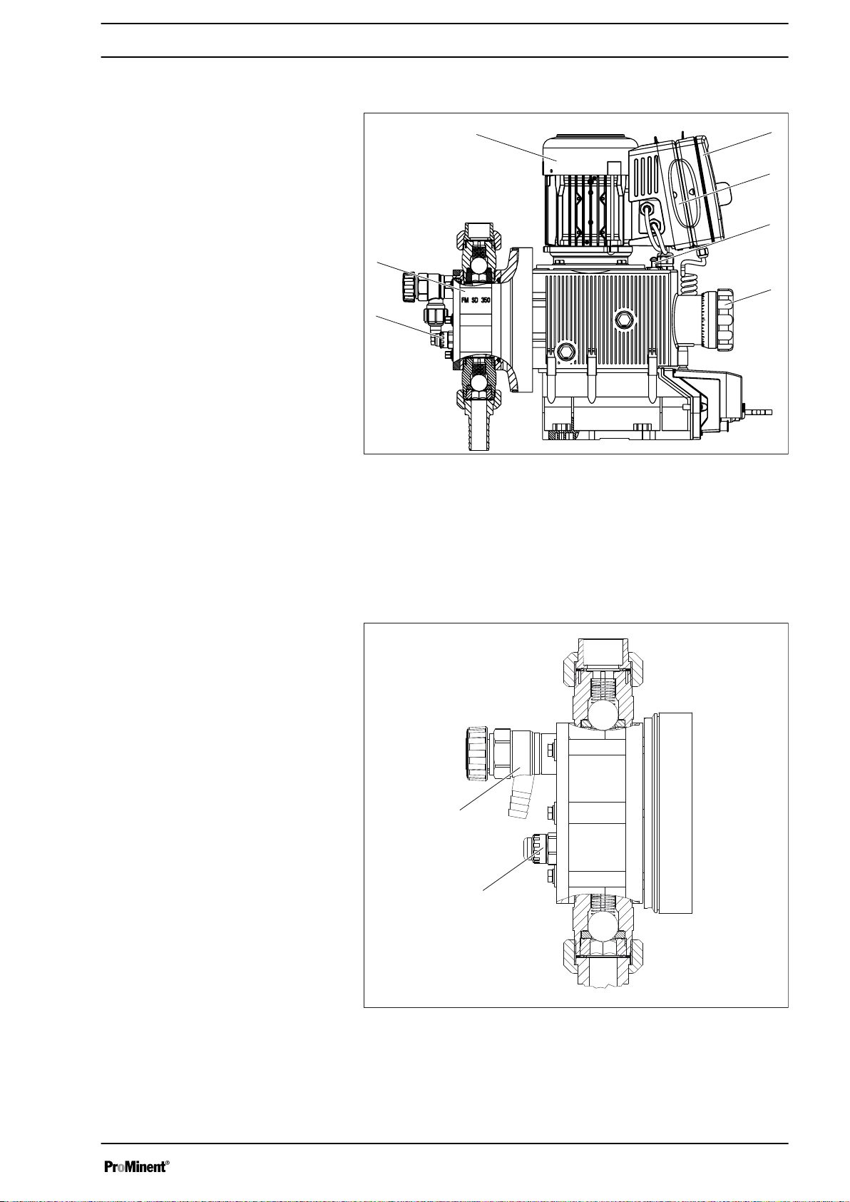
Fig. 3: Overview of Sigma X - S3Cb equipment
1 HMI control unit
2 Frequency converter
3 Drive unit
4 Stroke length adjustment wheel
5 Drive motor
6 Liquid end
7 Diaphragm rupture sensor
Fig. 4: Sigma control elements
1 Bleed valve (optional)
2 Diaphragm rupture sensor (visual)
13
Page 14
P_SI_0180_SW
3
1
5
4
2
10
9
8
6
7
P_SI_0193_SW
6
7
543
2
1
8
Overview of equipment and control elements
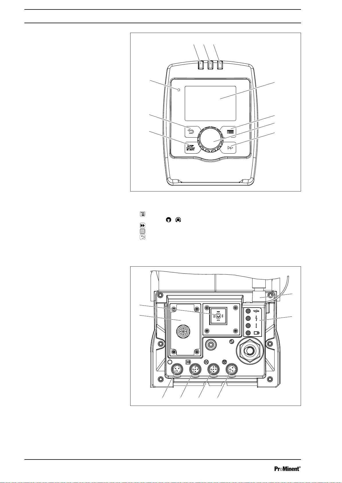
Fig. 5: Control elements for HMI Sigma X Control type
1 LCD screen
2
[Menu]
3
Clickwheel
4
5
6
7 "Bluetooth active” display (blue)
8 Fault indicator (red)
9 Warning indicator (yellow)
10 Operating indicator (green)
key
[Priming]
[STOP/START]
[Back]
key
key
key
Fig. 6: Connector cover control elements
1 Relay and mA-output (option)
2
3 "Diaphragm rupture" socket
4 "External control" terminal
5 "Metering monitor" terminal
Slot for optional module (PROFIBUS®, ...)
14
Page 15

4.1 Control elements
12012
12000
CONTACT
memory
l/h
CAN
open
hh
B1087
1
3
2
120120
12000
Dosing monitor!
CONTACT
memory
l/h
CAN
open
hh
12000
ANALOGUE
hh
Input signal < 4 mAInput signal < 4 mA
i < 4 mAi < 4 mA
B1088
a)
b)
i < 4 mA!
Pressure display, identifier and fault dis‐
plays on the LCD screen
Overview of equipment and control elements
6 "Level switch" terminal
7 "CAN bus" socket (external)
8 LEDs (as Fig. 5) and CAN bus status LED (external)
not shown Stroke length adjustment wheel
Use this overview to familiarise yourself with the keys
and the other control elements on the pump!
Fig. 7: Construction of continuous display
1 Status bar
2 Continuous display, central area
3 Secondary display
Refer to the chapter entitled "Main displays and secondary displays" in the
Appendix for the different main displays and secondary displays.
The LCD screen supports the operation and adjustment of the pump by
providing different information and identifiers:
Fig. 8: a) Continuous display with warning message; b) Continuous display
with fault message. Explanation of the symbols in the following tables.
The above Figure, Part a) shows that:
n The pump is in operation
n Is in
n A metering monitor is connected
n A log entry has been made
n A warning message for the
n The capacity of 12.0 l/h has been set
n The stroke rate is 12,000 strokes / h
‘Contact’
operating mode with "memory" stroke memory
‘metering monitor’
is pending
15
Page 16
dia
off
Overview of equipment and control elements
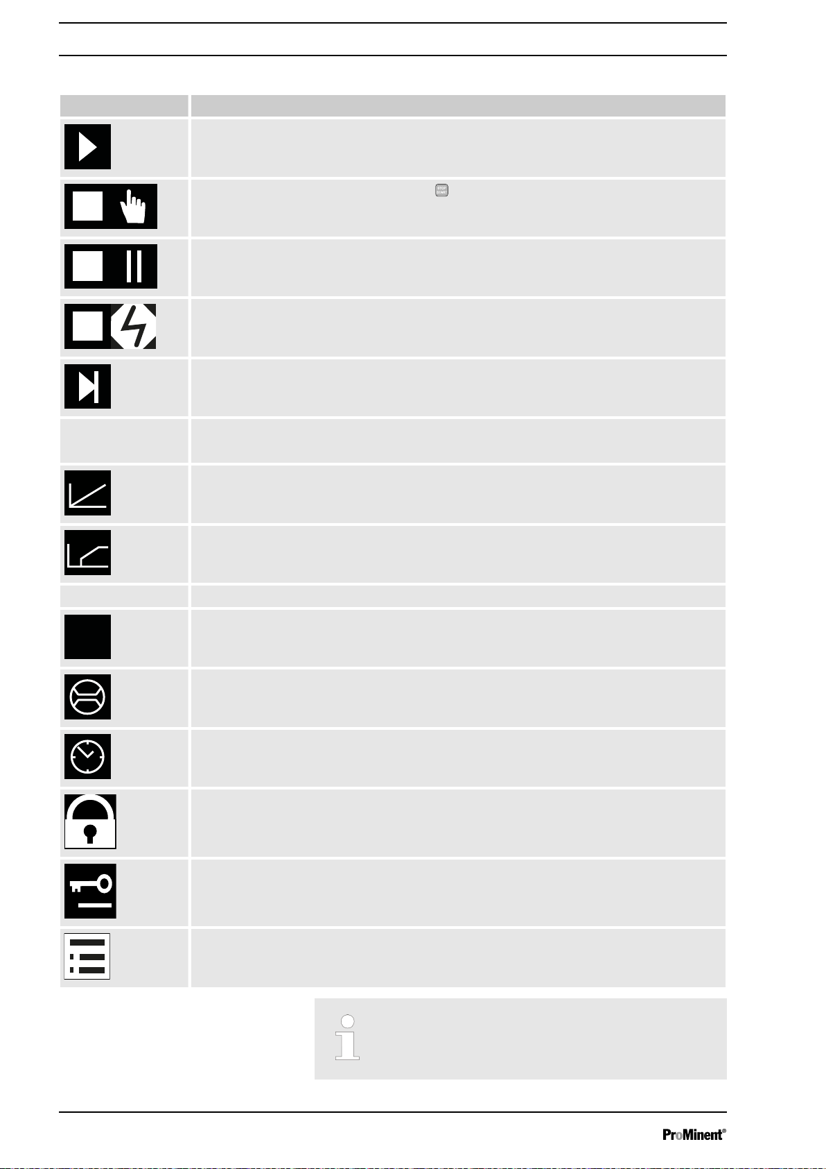
Tab. 1: Identifier and error displays:
Identifier Meaning
The pump is working or waiting for a starting signal.
‘memory’
The pump was manually stopped using the
The pump was remotely stopped (Pause) - via the "External" socket.
The pump was stopped by an error.
Only with cyclical batch metering: the pump is waiting for the next cycle.
Only in
The "Stroke memory" auxiliary function has been set.
The pump is in
The
The pump is in
The
‘CONTACT’
‘Curve è linear’
and
‘BATCH’
‘ANALOGUE’
type of processing is set.
‘ANALOGUE’
operating mode.
operating mode.
‘Curve è Upper side band’
operating modes:
type of processing is set.
[STOP/START]
key.
‘AUX’
The pump is currently pumping at auxiliary capacity and/or auxiliary frequency.
The diaphragm rupture warning system is disabled.
A "Flow Control" metering monitor is connected.
The timer is active.
Only with
Only with
The pump is in the
‘Password’
‘Password’
: the pump software is locked.
: the pump software has been temporarily unlocked.
‘Menu’
(Set up).
Further explanations can be found in the "Trouble‐
shooting" chapter.
16
Page 17
Overview of equipment and control elements
The pump only shows the metering volume and the
capacity in the calibrated state in l or l/h or in gal or
gal/h.
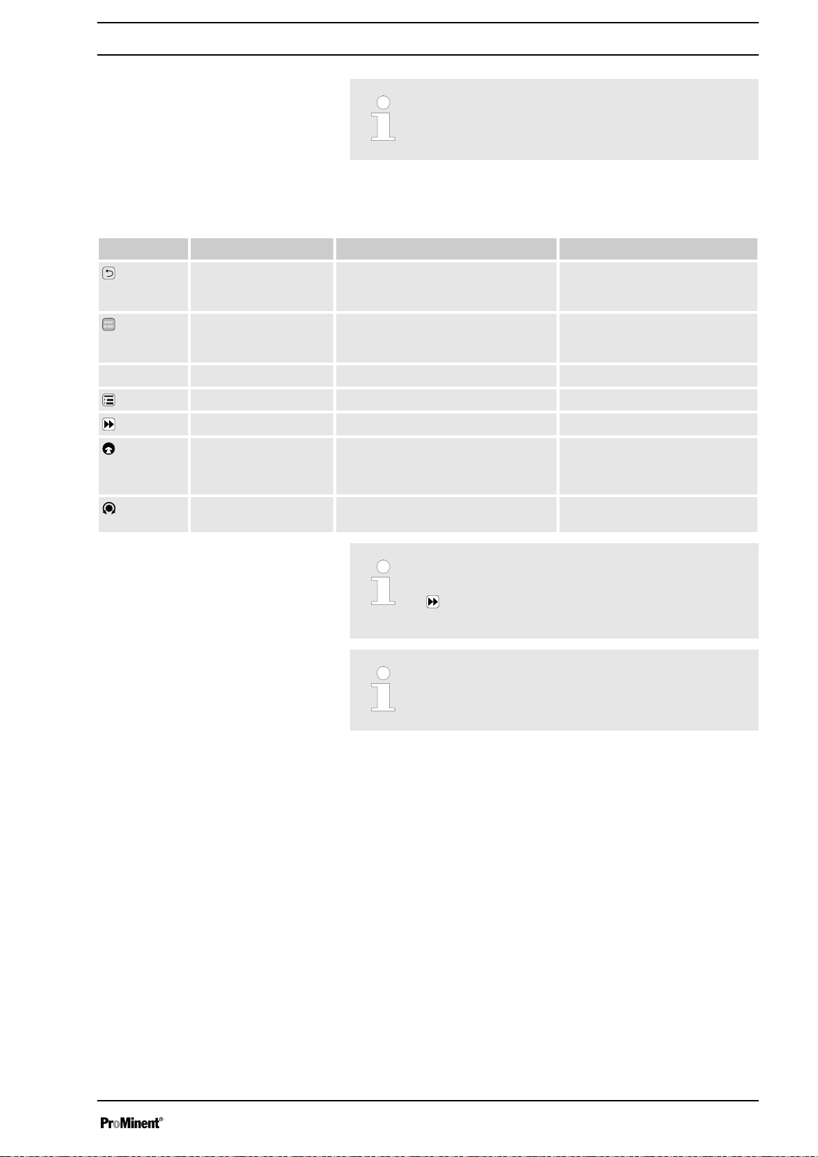
4.2 Key functions
Key Application In the continuous displays In the menu
[Back]
press - Move back to the previous menu
point (or a continuous display) without saving
press Stop pump, Stop pump,
[STOP/
START]
Start pump Start pump
[Menu]
[Priming]
[Clickwheel]
[Clickwheel]
press Move to the menu Move back to a continuous display
press Priming * Priming *
press Start batch (only in
mode),
Acknowledge errors
turn Switch between the continuous dis‐
plays
‘Batch’
operating
Move to next menu option (or a
continuous display)
Confirm entry and save
Change figure or change selection
* When priming the pump does not run at maximum
stroke rate.
[Priming] is pressed in ‘Stop’ state, then [Priming]
If
has top priority as long as the button is pressed.
Refer to the "Set-up basics" chapter to adjust figures
17
Page 18
0
s s
a)
180 360 0
b)
180 360
ω ω
P_PL_0009_SW
P_SI_0120_SW
s
t
P_SI_0103_SW
s
t
Functional description
5 Functional description
Pump
5.1
The metering pump is an oscillating diaphragm pump, the stroke length of
which can be adjusted. An electric motor drives it. The slide rod transmits
the stoke motion to the diaphragms.
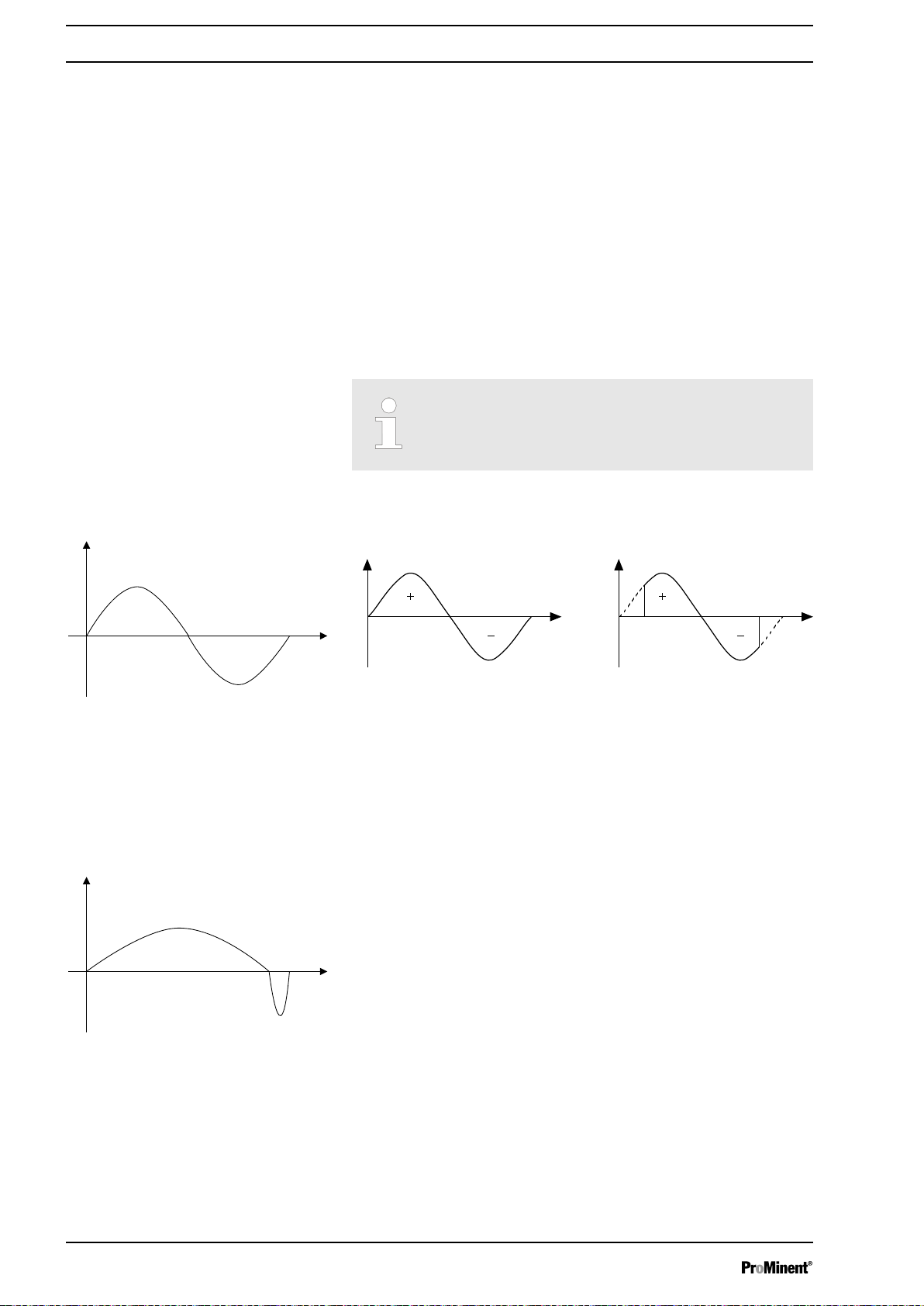
Illustration of the stroke movement
The stroke movement of the displacement body is continuously detected
and regulated so that the stroke is performed according to a previously set
metering profile - see chapter.
‘Metering’ ‘setting’
.
The following metering profiles are available:
n Normal
n Metering optimised
n Priming optimised
Every metering profile is ineffective below the switchover frequency for Start/Stop mode.
Normal
Fig. 9: Stroke movement at a) maximum stroke length and b) reduced
stroke length.
s Stroke velocity
⍵ Cam rotational angle
+ Discharge stroke
- Suction stroke
Metering optimised
With a metering optimised metering profile, the discharge stroke is elon‐
gated and the suction stroke is executed as quickly as possible. This set‐
ting is for example suitable for those applications that require optimum
mixing ratios and the most continuous chemical mixing possible.
Priming optimised
18
Page 19
5.2
4
2
1
5
3
13
P_SI_0104_SW
s
t
Functional description
With a priming optimised metering profile, the suction stroke is elongated
as much as possible, which facilitates the precise and problem-free
metering of viscous and gaseous media. Select this setting to minimise the
NPSH value as well.
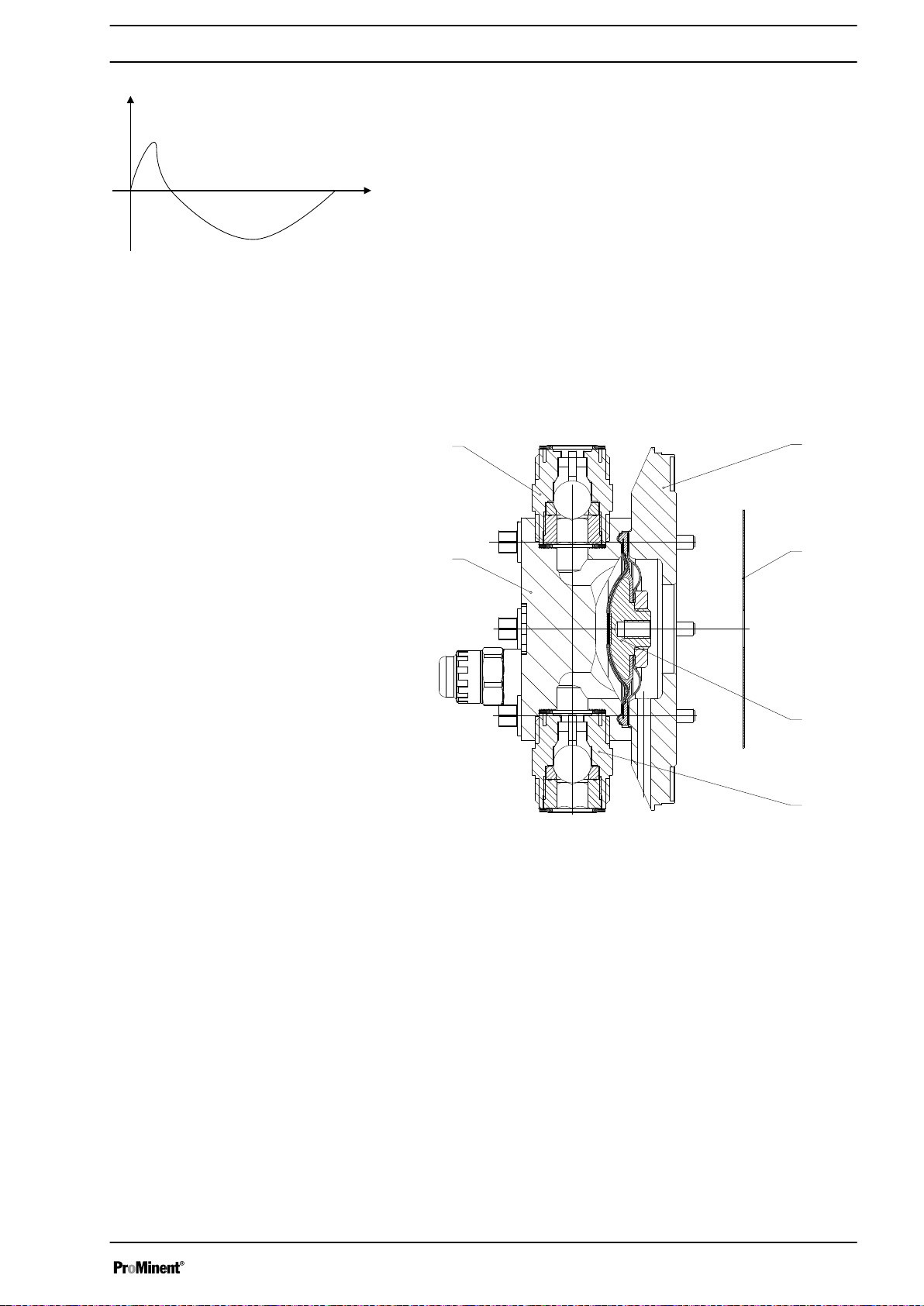
Liquid end
The diaphragm (2) hermetically shuts off the pump volume of the dosing
head (4) towards the outside. The suction valve (1) closes as soon as the
diaphragm (2) is moved in to the dosing head (4) and the feed chemical
flows through the discharge valve (3) out of the dosing head. The dis‐
charge valve (3) closes as soon as the diaphragm (2) is moved in the
opposite direction due to the vacuum pressure in the dosing head and
fresh feed chemical flows through the suction valve (1) into the dosing
head. One cycle is thus completed.
Fig. 10: Cross-section through the liquid end
1 Suction valve
2 Diaphragm
3 Discharge valve
4 Dosing head
5 Backplate
13 Safety diaphragm
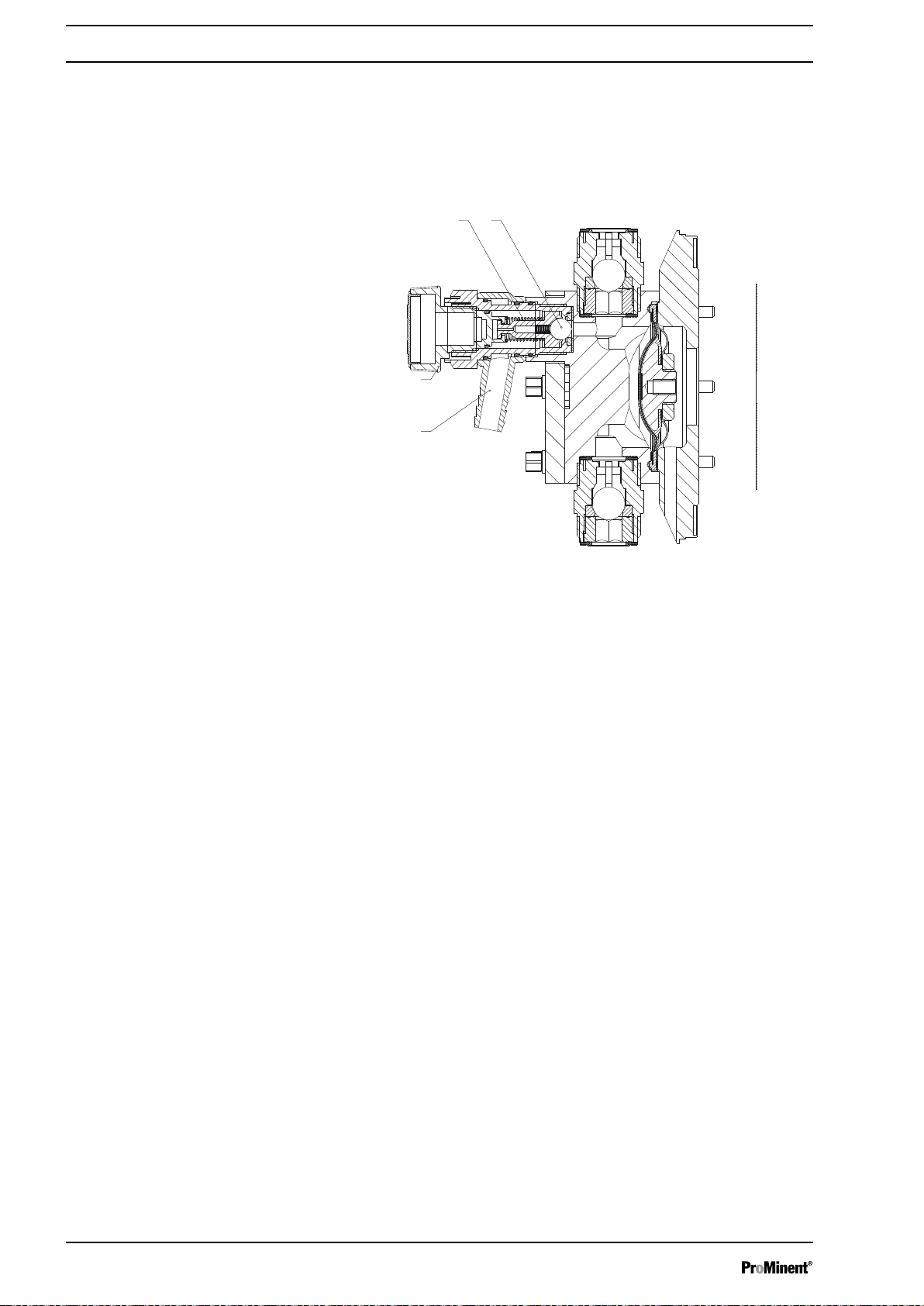
5.3 Bleed valve and integrated relief valve
Bleed valve
Integral relief valve
Turning the rotary dial (3) on the bleed valve to "open" causes it to open
and the liquid end can be bled. Or it is used as a priming aid for priming
against pressure. The feed chemical flows out through the hose connec‐
tion (5), e.g. into a storage tank.
The integral relief valve operates in the "close" position as a simple,
directly controlled relief valve. As soon as the pressure exceeds the pres‐
sure value, which is preset using the large spring (1), it lifts the ball (2).
The feed chemical flows out through the hose connection (5), e.g. into a
storage tank.
19
Page 20
1 2
5
3
P_SI_0109
Functional description
The integral relief valve can only protect the motor and the gear, and then
only against impermissible positive pressure that is caused by the
metering pump itself. It cannot protect the system against positive pres‐
sure.
The integral relief valve works as a bleed valve as soon as the rotary dial
(3) is turned to "open": The valve opens and the liquid end can be bled. Or
it is used as a priming aid for priming against pressure.
5.4 Multi-layer safety diaphragm
Fig. 11: Relief valve and integrated relief valve
1 Spring, large
2 Ball
3 Rotary dial
5 Hose connection
With the visual diaphragm rupture sensor, the lowered red cylinder (6)
springs forward beneath the transparent cover (7) so that it then becomes
clearly visible
Fig. 12.
With the electrical diaphragm rupture sensor, a switch is switched. A con‐
nected signalling device must signal the diaphragm rupture.
Fig. 12: Visual diaphragm rupture sensor, triggered and untriggered
The electrical diaphragm rupture sensor is connected to the "diaphragm
rupture indicator" terminal. If a diaphragm ruptures, the red LED "Fault"
display lights up on the pump and the identifier "Error" and
‘dia’
flash on
the LCD screen.
5.5 Operating modes
The operating modes are selected via the
‘Operating mode’
operating modes may not be present depending on the identity code.)
20
menu (some
Page 21

‘Manual’
unit.
Functional description
operating mode: The stroke rate is set manually on the control
operating mode
‘Batch’
‘Contact’
operating mode
This operating mode provides the option of working with large transfer fac‐
tors (up to 99,999). Metering can be triggered either by pressing the
[Clickwheel]
via a contact or a semiconductor switching element. It is possible to preselect a metering volume (batch) or a number of strokes using the
[Clickwheel]
This operating mode provides the option of controlling the pump externally
by means of potential-free contacts (e.g. by means of a contact water
meter). The "Pulse Control" option enables you to preselect the number of
strokes (a scaling or transfer factor of 0.01 to 99.99) in the
menu.
‘Analogue’
logue current signal via the "External control" terminal. The processing of
the current signal can be preselected using the control unit.
‘BUS’
FIBUS® DP interface). This operating mode provides the option of control‐
ling the pump via BUS – see “Supplementary instructions for Sigma Con‐
trol type SxCb pumps with Can connector” or “Supplementary instructions
for delta® DLTa and Sigma SxCb with PROFIBUS®".
or by a pulse received via the "External control" terminal or
in the
‘Settings’
menu.
‘Settings’
operating mode The stroke rate is controlled using an ana‐
operating mode: (Identity code, control version: CANopen or PRO‐
5.6 Functions
The following functions can be selected using the
"Calibrate" function: The pump can also be operated in a calibrated state
in all operating modes. In this case, the corresponding continuous displays
can then indicate the metering volume or the capacity directly. Calibration
is maintained throughout the stroke rate range. The calibration is also
maintained when the stroke length is altered by up to ±10% scale divi‐
sions.
"Auxiliary frequency" function: Enables a freely selectable and program‐
mable stroke rate to be switched on in the
controlled via the "External control" terminal. This auxiliary frequency has
priority over the operating mode stroke rate settings.
"Flow" function: Stops the pump when the flow is insufficient, provided a
metering monitor is connected. The number of defective strokes, after
which the pump is switched off, can be set in the
The following functions are available as standard:
‘Settings’
‘Settings’
‘Settings’
menu:
menu, which can be
menu.
"Level switch" function: Information about the liquid level in the dosing tank
is reported to the pump control. To do this, a two-stage level switch must
be fitted, which is connected to the "Level switch" terminal.
21
Page 22

Functional description
"Pause" function:
control" terminal. The "Pause" function only works via the "External con‐
trol" terminal.
The following functions are triggered by a key press:
"Stop" function: The pump can be stopped without disconnecting it from
the mains/power supply by pressing
The pump can be remotely stopped via the "External
[STOP/START]
.
"Priming" function
5.7 Options
Relay option
[]
Priming.
Priming can be triggered by pressing
The pump has several connection possibilities for the following options:
"Output relay" option: In the event of fault signals, warning signals, stop‐
ping of the pump or tripped level switches, the relay connects to complete
an electric circuit (for alarm horns etc.).
The relay can be retrofitted via a knock-out in the drive unit.
The various functions can be adjusted – see "Settings" - "Relays” chap‐
ters.
"Fault indicating relay and semiconductor relay" option:
fault signals, warning signals, stopping of the pump or tripped level
switches, the fault indicating relay connects to complete an electric circuit
(for control panel etc.).
In addition to the fault indicating relay, the pacing relay can be used to
make a contact every stroke.
Other functions can be adjusted – see "Settings" - "Relays” chapters. The
option can be retrofitted via a knock-out in the drive unit.
In the event of
"0/4-20 mA analogue current output and
fault indicating relay” option
5.8
Function and fault indicator
5.8.1 LCD screen
The current output I signal indicates the pump's actual calculated metering
volume.
The "0/4-20 mA analogue current output and fault indicating relay" option
can be retrofitted via a knock-out in the control unit.
The option also always includes a semiconductor relay - see above. Other
functions can be adjusted – see "Settings" - "Relays” chapters.
The operating and fault statuses are indicated by the three or four LED
displays and the
If a fault occurs, the identifier
sage – see “Troubleshooting” chapter
‘Error’
identifier on the LCD screen:
‘Error’
appears and an additional error mes‐
22
Page 23

5.8.2 LED displays
Pump device LEDs
Functional description
- see "Troubleshooting" chapter
Fault indicator (red)
Warning indicator (yellow)
Operating indicator (green)
CAN bus status LED (external)
The fault indicator lights up if the fluid level in the dosing tank falls below
the second switching point of the level switch (20 mm residual filling level
in the dosing tank).
It also lights up with all other faults - refer to "Troubleshooting" chapter.
The warning indicator lights up if the fluid level in the dosing tank falls
below the first switching point of the level switch.
It also lights up with all other warnings - refer to "Troubleshooting" chapter.
The operating indicator lights up if the pump is ready for operation and
there are no fault or warning alerts. It briefly goes out as soon as the pump
has performed a stroke.
This LED on the power end is the top one in the row of 4 LEDs.
Colour Flash code Cause Conse‐
green lit Bus status
OPERA‐
TIONAL
quence
Normal bus
mode
Remedy
-
green flashing Bus status
PREOPERA‐
TIONAL
red any Bus error no meas‐
5.9 Hierarchy of operating modes, functions and fault statuses
The different operating modes, functions and fault statuses have a dif‐
ferent effect on whether and how the pump reacts.
The following list shows the order:
1. - Priming
2. - Fault, Stop, Pause
3. - Auxiliary frequency (external frequency changer)
4. - Manual, External contact, Batch, External analogue
currently no
measured
value com‐
munication
ured value
transmission
wait briefly.
Disconnect
HMI then
reconnect
Check
whether the
CAN con‐
nection is
faulty.
Notify
Service
Comments:
re 1 - “Priming" can take place in any mode of the pump (providing it is
re 2 - "Fault", "Stop" and "Pause" stop everything apart from "Priming".
re 3 - The "Auxiliary frequency" stroke rate always has priority over the
working).
stroke rate specified by an operating mode listed under 4.
23
Page 24
h
P_MOZ_0016_SW
A
A
P_MOZ_0018_SW
Assembly
6 Assembly
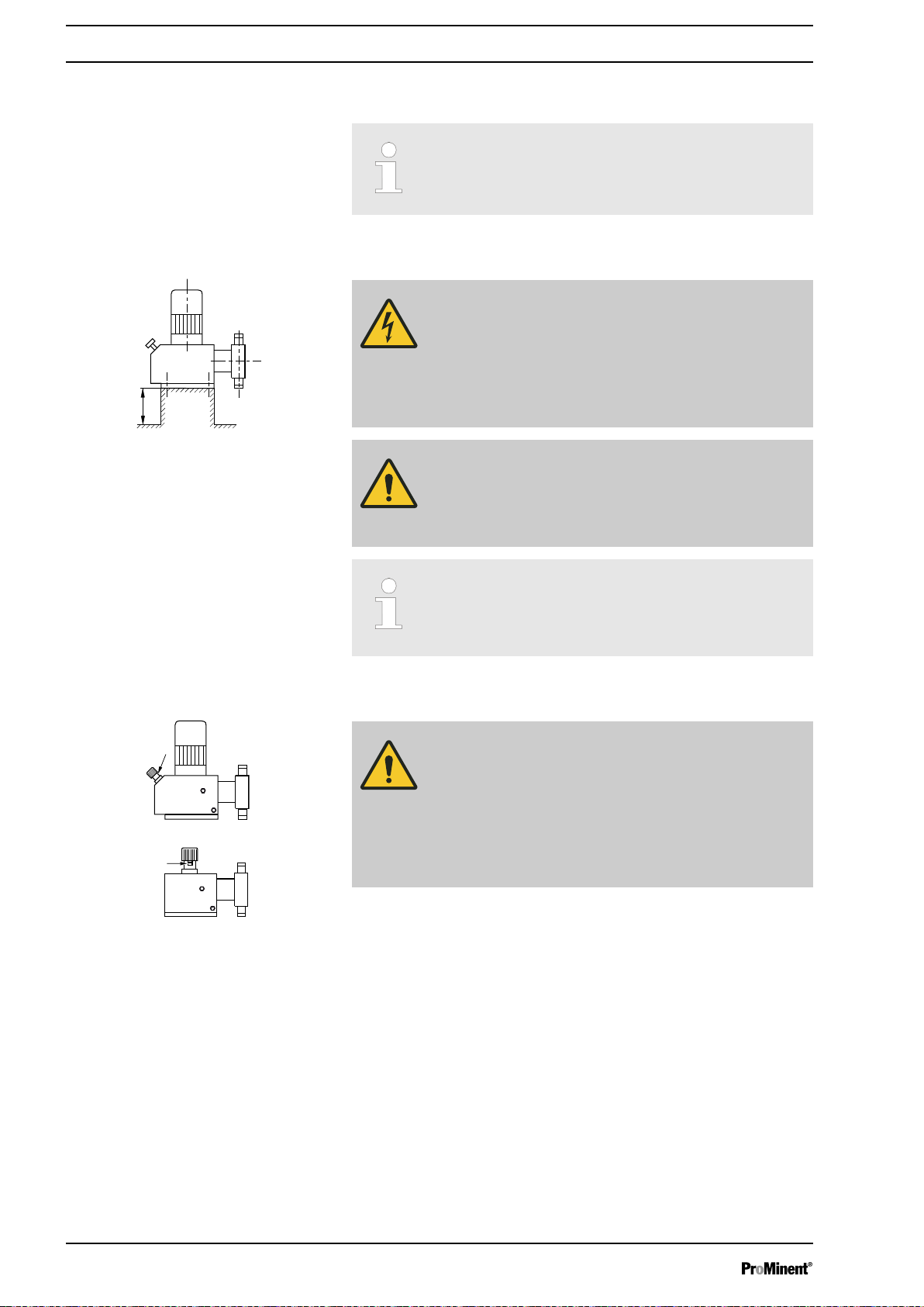
Base
Compare the dimensions on the dimension sheet with
those of the pump.
WARNING!
Danger of electric shock
If water or other electrically conducting liquids penetrate
into the drive housing, in any other manner than via the
pump's suction connection, an electric shock may occur.
– Position the pump so that it cannot be flooded.
Fig. 13
Space requirement
Fig. 14
WARNING!
The pump can break through the base or slide off it
– Ensure that the base is horizontal, flat and perma‐
nently load-bearing.
Capacity too low
Vibrations can disturb the liquid end valves.
–
Do not allow the base to vibrate.
CAUTION!
Danger from incorrectly operated or inadequately main‐
tained pumps
Danger can arise from a poorly accessible pump due to
incorrect operation and poor maintenance.
– Ensure that the pump is accessible at all times.
–
Adhere to the maintenance intervals.
Position the pump so that control elements, such as the stroke length
adjustment knob, the indicating dial A or the oil inspection window, are
accessible.
In so doing, ensure there is enough space to carry out an oil change (vent
screws, oil drain plugs, oil trough ...).
If the HMI is mounted remotely from the pump: a clearly marked Stop
mechanism must be installed in the direct vicinity of the pump for emer‐
gencies!
24
Page 25
1
3
2
f
f
f
P_MOZ_0017_SW
Fig. 15
DNm
m
P_MOZ_0015_SW
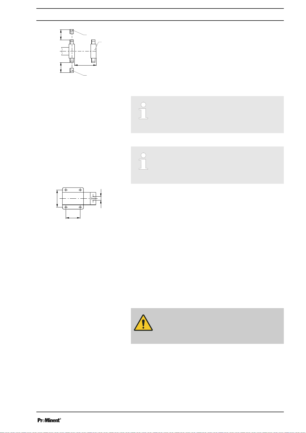
Liquid end alignment
Fastening
Assembly
1 Discharge valve
2 Dosing head
3 Suction valve
Ensure there is sufficient free space (f) around the dosing head as well as
the suction and discharge valve so that maintenance and repair work can
be carried out on these components.
Capacity too low
The liquid end valves cannot close correctly if they are
not upright.
–
Ensure that the discharge valve is upright.
Capacity too low
Vibrations can disturb the liquid end valves.
–
Secure the metering pump so that no vibrations can
occur.
Fig. 16
Take the dimensions (m) for the fastening holes from the appropriate
dimensions- or data sheets.
Use appropriate bolts to fix the pump base to the supporting floor.
Mounting the HMI user control
If ordered with the wall mounting, the HMI can be mounted directly on a
wall.
Install the HMI in the immediate vicinity of the pump. If not provided for, fit
a circuit breaker there - refer to the "Installation, electrical" chapter. Ensure
that the system is arranged ergonomically.
When doing so, consider the available cable length.
Prevent tripping hazards.
Refer to the relevant dimensional drawing for the dimensions of the HMI
and fixing holes.
CAUTION!
Warning of faulty operation
– Do not install the HMI and cable too close to devices
and cabling that emit strong electrical interference.
25
Page 26

Installation
7 Installation
7.1 Installation, hydraulic
CAUTION!
Danger of injury to personnel and material damage
Disregard of technical data during installation may lead
to personal injuries or damage to property.
– Observe the technical data - refer to the "Technical
data" chapter and, where applicable, the operating
instructions for the accessories.
WARNING!
Danger of fire with flammable feed chemicals
– Only metering pumps with the identity code option
"Multi-layer safety diaphragm with rupture signalling
with electrical signal" are permitted to meter flam‐
mable media, with back pressures over 2 bar and if
the operator puts in place the appropriate safety pre‐
cautions.
WARNING!
Warning of feed chemical reactions to water
Feed chemicals that should not come into contact with
water may react to residual water in the liquid end that
may originate from works testing.
– Blow the liquid end dry with compressed air through
the suction connector.
–
Then flush the liquid end with a suitable medium
through the suction connector.
WARNING!
The following measures are beneficial when working
with highly aggressive or hazardous feed chemicals:
– Install a bleed valve with recirculation in the storage
tank.
Install a shut-off valve on the discharge or suction
–
side.
CAUTION!
Warning of feed chemical spraying around
PTFE seals, which have already been used / com‐
pressed, can no longer reliably seal a hydraulic connec‐
tion.
– New, unused PTFE seals must always be used.
26
Page 27
Installation
CAUTION!
Suction problems are possible
The valves may no longer close properly with feed
chemicals with a particle size of greater than 0.3 mm.
– Install a suitable filter in the suction line.
CAUTION!
Warning of the discharge line rupturing
With a closed discharge line (e.g. from a clogged dis‐
charge line or by closing a valve), the pressure that the
metering pump generates can reach several times more
than the permissible pressure of the system or the
metering pump. This could lead to lines rupturing
resulting in dangerous consequences with aggressive or
hazardous feed chemicals.
– Install a relief valve that limits the pressure of the
pump to the maximum permissible operating pres‐
sure of the system.
CAUTION!
Warning against rupturing of suction or discharge lines
Hose lines with insufficient pressure rating may rupture.
– Only use hose lines with the required pressure
rating.
CAUTION!
Uncontrolled flow of feed chemical
Feed chemical can press through the metering pump in
an uncontrolled manner in the event of excessive pri‐
ming pressure on the suction side of the metering pump.
– Do not exceed the maximum permissible priming
pressure for the metering pump or
Set up the installation properly.
–
CAUTION!
Warning about lines coming loose
If suction, discharge and relief lines are installed incor‐
rectly, they can loosen / disconnect from the pump con‐
nection.
– Only use original hoses with the specified hose
diameter and wall thickness.
Only use clamp rings and hose nozzles that fit the
–
respective hose diameter.
– Always connect the lines without mechanical ten‐
sion.
27
Page 28
P_SI_0021
P_SI_0022
1
1
2
3
4
5
P_MOZ_0020_SW
1
2
3
P_MOZ_0021_SW
Installation
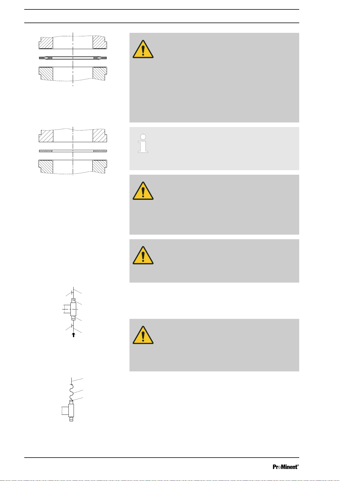
Fig. 17: Moulded composite seals with
corrugated insert
CAUTION!
Warning of leaks
Leaks can occur on the pump connection depending on
the insert used.
– The pump is supplied with PTFE moulded compo‐
site seals with a flare, which are used for the pump
connectors, which seal the connectors between
grooved pump valves and ProMinent grooved
inserts - see
Ä Further information on page 26
.
– Use an elastomer flat seal in the event that an
unflared insert is used (e.g. third party part) - see
Ä Further information on page 26
Precise metering is only possible when the back
–
.
pressure is maintained above 1 bar at all times.
–
If metering at atmospheric pressure, a back pres‐
sure valve should be used to create a back pressure
of approx. 1.5 bar.
Fig. 18: Elastomer flat seal for a smooth
insert
Fig. 19: Manometer connector options
CAUTION!
Warning of backflow
A back pressure valve, a spring-loaded injection valve, a
relief valve, a foot valve or a liquid end do not represent
absolutely leak-tight closing elements.
– Use a shut-off valve, a solenoid valve or a vacuum
breaker for this purpose.
CAUTION!
To check the pressure conditions in the piping system it
is recommended that connecting options for a manom‐
eter are provided close to the suction and pressure con‐
nector.
1 Manometer socket
2 Discharge line (pipe)
3 Discharge valve
4 Suction valve
5 Suction line (pipe)
CAUTION!
Connect the pipelines to the pump so that no residual
forces act on the pump, e.g. due to the offsetting, weight
or expansion of the line.
Only connect steel or stainless steel piping via a flexible
piping section to a plastic liquid end.
Fig. 20: Steel pipeline at the liquid end
1 Steel piping
2 Flexible pipe section
3 Plastic liquid end
28
Page 29
Integral relief valve or integral bleeder
valve
Installation
WARNING!
Product can be dangerously contaminated
Only with "Physiologically safety with regard to wetted
materials” version:
If the integral bleed valve or the integral relief valve
opens, the feed chemical comes into contact with phys‐
iologically harmful seals.
– Do not route feed chemical that escapes from the
integral bleed valve or the integral relief valve back
into the process.
CAUTION!
Danger due to incorrect use of the integral relief valve
The integral relief valve can only protect the motor and
the gear, and then only against impermissible positive
pressure that is caused by the metering pump itself. It
cannot protect the system against positive pressure.
– Protect the motor and gear of the system against
positive pressure using other mechanisms.
– Protect the system against illegal positive pressure
using other mechanisms.
CAUTION!
Warning of feed chemical spraying around
If no overflow line is connected to the integral relief valve
or the integral bleeder valve, feed chemical will spray out
of the hose connector as soon as the relief valve opens.
– Always connect an overflow line to the integral relief
valve or the integral bleeder valve and feed it back
into the storage tank or - if required by the regula‐
tions - into a special storage tank.
CAUTION!
Danger of cracking
Cracks on the PVT liquid end can occur if a metal over‐
flow line is connected to the relief valve.
– Never connect a metal overflow line to the relief
valve.
CAUTION!
Danger of the integral relief valve failing
The integral relief valve no longer operates reliably with
feed chemicals that have a viscosity of greater than 200
mPa s.
– Only use the integral relief valve with feed chemicals
that have a viscosity of up to 200 mPa s.
29
Page 30
P_SI_0023
Installation
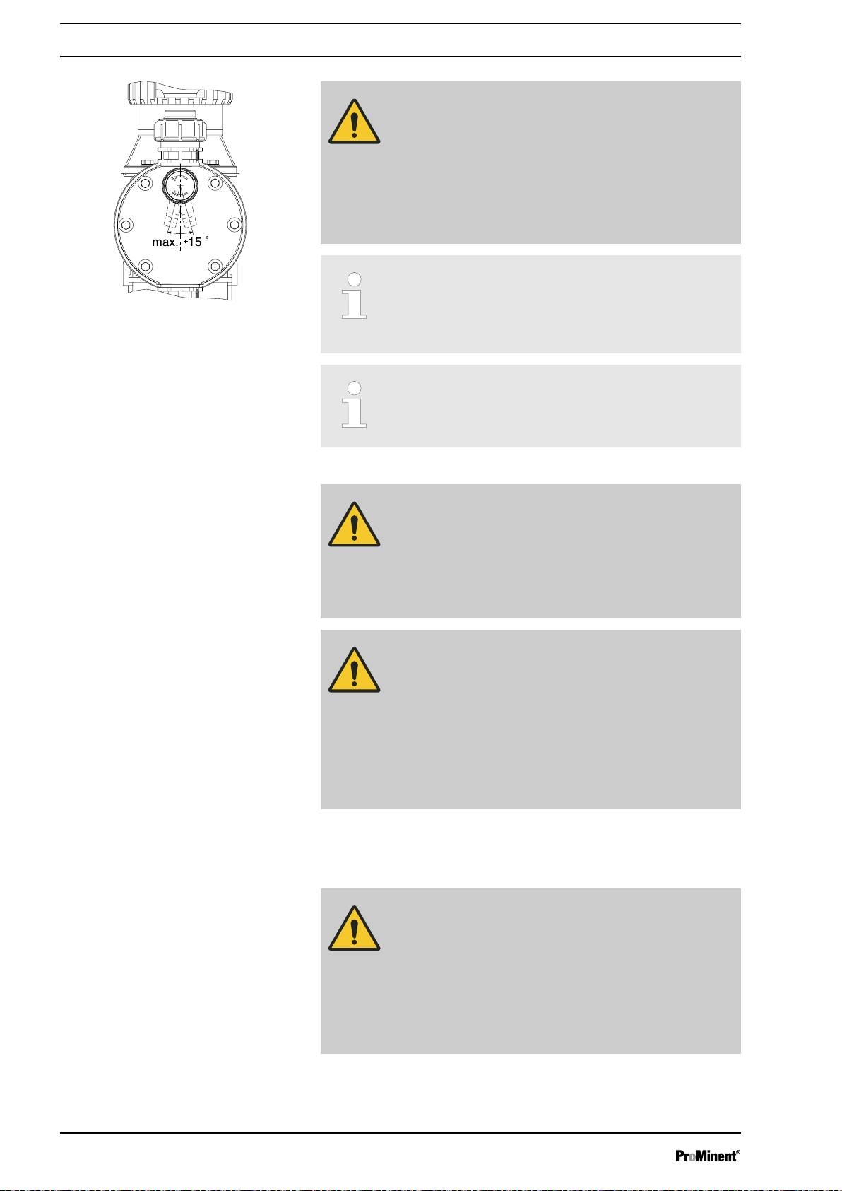
Fig. 21: Permissible alignment of the relief
valve
CAUTION!
Warning of leaks
Feed chemical, which remains in the overflow line at the
relief valve or bleeder valve, can attack the valve or
cause it to leak
– Route the overflow line with a continuous slope and
moreover with the hose nozzle pointed downwards see .
If the overflow line is fed into the suction line, the bleed
function is blocked.
Therefore lead the overflow line back into the storage
tank.
When operating the integral relief valve close to the
opening pressure, a minimal overflow into the overflow
line can occur.
Diaphragm rupture sensor
7.1.1 Basic installation notes
Safety notes
CAUTION!
Danger resulting from unnoticed diaphragm rupture
If the pump has been ordered with an electric diaphragm
rupture sensor, it still has to be installed.
– Screw the enclosed diaphragm rupture sensor into
the liquid end.
CAUTION!
Warning of unnoticed diaphragm rupture
Only above approximately 2 bar system back pressure is
a signal generated in the event of the rupture of a dia‐
phragm.
– Only rely on the diaphragm rupture sensor with back
pressures of greater than 2 bar.
Or install a back pressure valve and set it to a min‐
imum of 2 bar – if the installation permits this.
CAUTION!
Danger resulting from rupturing hydraulic components
Hydraulic components can rupture if the maximum per‐
missible operating pressure is exceeded.
– Never allow the metering pump to run against a
closed shut-off device.
With metering pumps without integral relief valve:
–
Install a relief valve in the discharge line.
30
Page 31

P_MOZ_0043_SW
2
1
A)
B)
*
PD
1
2
Installation
CAUTION!
Hazardous feed chemicals can escape
With hazardous feed chemicals: Hazardous feed chem‐
ical can leak out when using conventional bleeding pro‐
cedures with metering pumps.
– Install a bleed line with a return into the storage
tank.
Shorten the return line so that it does not dip into the feed chemical
in the storage tank.
Fig. 22: (A) standard installation, (B) with pulsation damper
1 Main line
2 Storage tank
Legend for hydraulic diagram
Symbol Explanation Symbol Explanation
Metering pump Foot valve with filter meshes
Injection valve Level switch
Multifunctional valve Manometer
7.2 Installation, electrical
General safety notes
WARNING!
Danger of electric shock
Unprofessional installation may lead to electric shocks.
– Crimp cable end sleeves onto all shortened cable
cores.
Only technically trained personnel are authorised to
–
undertake the electrical installation of the device.
31
Page 32

Installation
WARNING!
Danger of electric shock
A mains voltage may exist inside the motor or electrical
ancillaries.
– If the housing of the motor or electrical ancillaries
has been damaged, you must disconnect it from the
mains immediately. Only return the pump to service
after an authorised repair.
CAUTION!
Use ProMinent cables to avoid unnecessary problems.
What requires electrical installation?
7.2.1 Control connectors
What requires electrical installation?
n Level switch
n Diaphragm rupture sensor, electrical (optional)
n Metering monitor (optional)
n Relay (optional)
n External control
n mA output (optional)
n Bus connector (optional)
n Pump, power supply
CAUTION!
Incoming signals can remain without effect
If the universal control wire, the external/pacing cable or
the level monitoring cable is shortened below 1.20 m,
the pump does not detect that it is connected. Conse‐
quently a warning message (for example) can be sup‐
pressed.
– Do not shorten this cable below 1.20 m.
Level switch, diaphragm rupture sensor
(option) and metering monitor (option)
Connect the plugs of the level switch, diaphragm rupture sensor and
metering monitor to the corresponding sockets on the front side of the con‐
trol. If in doubt - refer to the "Overview of equipment and control elements”
chapter.
CAUTION!
Danger resulting from unnoticed diaphragm rupture
If the pump has been ordered with an electric diaphragm
rupture sensor, it must also be electrically installed.
– Electrically connect the enclosed diaphragm rupture
sensor.
32
Page 33

7.2.1.1 Relay
2
3
1
4
P_SI_0111_SW
P_SI_0043
7.2.1.1.1
Fault indicating relay 230 V
Installation
Only with flammable media:
WARNING!
Fire danger
The electric diaphragm rupture sensor must stop the
pump immediately after a diaphragm rupture and trigger
an alarm.
The pump must only be returned to Service once a new
diaphragm has been fitted.
If another switching function is required, the pump can be reprogrammed
in the
‘Relay’
menu.
The relay can be retrofitted and is operational once it has been plugged
into the relay board.
Fig. 23: Pump assignment
Fault indicating relay 230 V
Fault indicating relay 230 V
Fig. 24: Cable assignment
Data Value Unit
Maximum contact load at 230 V and 50/60
Hz:
8 A (resis‐
tive)
Minimum mechanical service life: 200,000 switching
operations
Pin assignment
To pin VDE cable Contact CSA cable
1 white NO (normally open) white
2 green NC (normally closed) red
4 brown C (common) black
33
Page 34

2
3
1
4
P_SI_0111_SW
P_SI_0044
Installation
7.2.1.1.2 Fault indicating and pacing relay option
The first switch is a relay. The pacing output is electrically-isolated by
means of an optocoupler with a semiconductor switch.
If another switching function is required, the pump can be reprogrammed
in the
The relay can be retrofitted and is operational once it has been plugged
into the relay board.
Fig. 25: Pump assignment
‘Relay’
menu.
Fault indicating relay (24 V)
Pacing relay
Fault indicating and pacing relay option
Fig. 26: Cable assignment
Data Value Unit
Maximum contact load at 24 V and 50/60
100 mA
Hz:
Minimum mechanical service life: 200,000 switching
operations
Data Value Unit
Residual voltage max. at I
= 1 µA 0.4 V
off max
Maximum current 100 mA
Maximum voltage 24 VDC
Closing time 100 ms
Pin assignment
To pin VDE cable Contact Relay
1 yellow NC (normally closed) or
NO (normally open)
Fault indi‐
cating relay
4 green C (common) Fault indi‐
cating relay
3 white NC (normally closed) or
Pacing relay
NO (normally open)
2 brown C (common) Pacing relay
34
Page 35

7.2.1.1.3 Current output and fault indicating / pacing relay (24 V)
2
3
1
4
P_SI_0010_SW
P_SI_0044
The module can be retrofitted and operates once it is plugged into the
module board.
The variable to be signalled for the current output can be selected in the
‘ANALOGUE OUTPUT’
If another switching function is required, the relay can be reprogrammed in
‘Relay’
the
menu.
Fig. 27: Pump assignment
Installation
menu.
Current output
Fault indicating / pacing relay (24 V)
Current output and fault indicating / pacing
relay (24 V)
Data Value Unit
Open circuit voltage: 8 V
Current range: 4 ... 20 mA
Ripple, max.: 80 μA ss
Load, max.: 250 Ω
Data Value Unit
Residual voltage max. at I
= 1 µA 0.4 V
off max
Maximum current 100 mA
Maximum voltage 24 VDC
Closing time 100 ms
To pin VDE cable Contact Relay
1 yellow "+" Current
output
Fig. 28: Cable assignment
4 green "-" Current
output
3 white NC (normally closed) or
NO (normally open)
Fault indi‐
cating /
pacing relay
2 brown C (common) Fault indi‐
cating /
pacing relay
35
Page 36

Universal control wire connection diagramUniversal control wire connection diagram
Site endSite end
CableCable
Pump, insidePump, inside
2 white / Contact
4 brown / GND
GND
External
activation
Function "External Contact"
(ProMinent external/contact cable)
2-core
1 brown / Pause
2 white / Contact
4 black / GND
3 blue / Analog
5 grey /Auxiliary
GND
GND
External
activation
1 brown / Pause
2 white / Contact
4 black / GND
3 blue / Analog
5 grey /Auxiliary
External
activation
1 brown / Pause
2 white / Contact
4 black / GND
3 blue / Analog
5 grey /Auxiliary
External
activation
1 brown / Pause
2 white / Contact
4 black / GND
3 blue / Analog
5 grey /Auxiliary
External
activation
GND
GND
+
-
Function "External Contact"
(ProMinent universal control wire)
5-core
"Pause" function
"Auxiliary rate" function
Function "External Contact"
Pulse frequency,
e.g. contact water meter, PLC etc.
Pulse frequency,
e.g. contact water meter, PLC etc.
Continuous contact (potential-free)
E.g. external on/off of control panel
Continuous contact (potential-free)
e.g. of control panel
0/4-20 mA
Analog signal,
e.g. of magnetic inductive
Flow meter
P_SI_0091_SW
Installation
7.2.1.2 External control
External control
36
Page 37

Technical data "External control"
1
54
2
3
P_BE_0014_SW
Semi-conductor switch elements with a residual voltage of -0.7 V (e.g.
transistors in open-collector circuits) or contacts (relays) can be used as
input switch elements.
Pin
Installation
Pin 1 = Pause input (activating func‐
Voltage with open contacts: approx. 5 V
tion)
Input resistance: 10 kΩ
Control:
n Potential-free contact (approx. 0.5
mA)
n Semiconductor switch (residual
voltage < 0.7 V)
2 = contact input Voltage with open contacts: approx. 5 V
Input resistance: 10 kΩ
Control:
n Potential-free contact (approx. 0.5
mA)
n Semiconductor switch (residual
voltage < 0.7 V)
min. contact duration: 20 ms
Max. pulse frequency: 25 pulses/s
3 = Analogue input Input load: approx. 120 Ω
4 = GND
5 = Auxiliary input Voltage with open contacts: approx. 5 V
Input resistance: 10 kΩ
Control:
n Potential-free contact (approx. 0.5
mA)
n Semiconductor switch (residual
voltage < 0.7 V)
The metering pump makes its first metering stroke at approx. 0.4 mA (4.4
mA) and enters into continuous operation at approx. 19.2 mA.
37
Page 38

GND
Inputs Outputs
Pump, inside
Block diagram Sigma Control
External
activation
Diaphragm
rupture
sensor
Stroke
sensor
Level
sensor
Fault indicating
relay
Warning
Network
Wiring connection
examples:
next page
Stroke
sensor
Flow Control
Diaphragm
rupture
sensor
3 white / NO (pacing relay)
Fault indicating
and
Pacing
relay
VDE cable:
Empty signal
2 brown / C (pacing relay)
1 white / NO
4 brown / C
1 yellow / NO (fault alert)
4 green / C (fault alert)
2 green / NC (fault alert)
3 brown / Pause
2 blue / Alarm
1 black / GND
1 brown / 5 V
2 white / Cod.
4 black / GND
3 blue
2 blue / Alarm
1 black / GND
VDE cable:
1 brown / Pause
2 white / Contact
4 black / GND
3 blue / Analog
5 grey /Auxiliary
P_SI_0089_SW
Installation
Fig. 29: Sigma Control block switching diagram
38
Page 39

Universal control wire connection diagramUniversal control wire connection diagram
Site endSite end
CableCable
Pump, insidePump, inside
2 white / Contact
4 brown / GND
GND
External
activation
Function "External Contact"
(ProMinent external/contact cable)
2-core
1 brown / Pause
2 white / Contact
4 black / GND
3 blue / Analog
5 grey /Auxiliary
GND
GND
External
activation
1 brown / Pause
2 white / Contact
4 black / GND
3 blue / Analog
5 grey /Auxiliary
External
activation
1 brown / Pause
2 white / Contact
4 black / GND
3 blue / Analog
5 grey /Auxiliary
External
activation
1 brown / Pause
2 white / Contact
4 black / GND
3 blue / Analog
5 grey /Auxiliary
External
activation
GND
GND
+
-
Function "External Contact"
(ProMinent universal control wire)
5-core
"Pause" function
"Auxiliary rate" function
Function "External Contact"
Pulse frequency,
e.g. contact water meter, PLC etc.
Pulse frequency,
e.g. contact water meter, PLC etc.
Continuous contact (potential-free)
E.g. external on/off of control panel
Continuous contact (potential-free)
e.g. of control panel
0/4-20 mA
Analog signal,
e.g. of magnetic inductive
Flow meter
P_SI_0091_SW
Installation
7.2.2 HMI operating unit
The HMI must be connected to the CAN socket above the LEDs of the
pump base if the pump is operated via the HMI.
39
Page 40

Installation
If the pump is operated without the HMI, the sealing cap supplied must be
plugged into the CAN socket above the LEDs of the pump base.
CAUTION!
Risk of short circuit
A short circuit may occur in the pump if liquid penetrates
into the CAN socket.
– Always plug a CAN plug or the sealing cap supplied
into the CAN socket.
CAUTION!
Danger of malfunctions
Incorrect operation via the CAN bus leads to malfunc‐
tions.
– Do not connect any other control (e.g. DXCa) to the
CAN socket when operating with the HMI con‐
nected.
7.2.3 Pump, power supply
WARNING!
Risk of electric shock
This pump is supplied with a grounding conductor and a
grounding-type attachment plug.
– To reduce the risk of electric shock, ensure that it is
connected only to a proper grounding-type recep‐
tacle.
WARNING!
Danger of electric shock
In the event of an electrical accident, it must be possible
to quickly disconnect the pump, and any electrical ancil‐
laries which may possibly be present, from the mains.
– Install an emergency cut-off switch in the mains
supply line to the pump and any electrical ancillaries
which may be present or
Integrate the pump and electrical ancillaries which
–
may be present in the emergency cut-off manage‐
ment of the system and inform personnel of the iso‐
lating option.
WARNING!
If the HMI cannot be operated directly from the pump
(specifically with versions with a cable longer than 2 m),
provide an option to disconnect the pump from the mains
power supply in the event of an emergency. Clearly
assign and label this option to the pump.
WARNING!
An on/off switch may not be fitted on the pump,
dependent on the identity code and installation.
40
Page 41

CAUTION!
Pump can be damaged
The pump can only be stopped when running via an:
– External cable
[Stop]
–
Use a relay or a contactor if the pump is to be definitively
actuated via the mains cable. However, take into
account the pump’s starting current.
key.
To be able to switch off the pump (to a zero-volts state)
independently from the entire installation (e.g. for repair),
use an electrical isolating device in the mains supply
cable, e.g. a mains switch or a plug / socket combina‐
tion. Clearly identify this isolating device as such.
Install the pump cable. Use the original cable supplied!
Installation
7.2.4 Other units
Other units
–
Key electrical data can be found on the pump’s
nameplate.
Install the other units on the basis of the documentation supplied.
41
Page 42

12012
2315
7.0
CONTACT
bar
l/h
Settings
Service
Language
Makro operating mode
Information
Menu
German
English
...
〉Language
Language
German
Menu/Information
Path, derived:
...
〉Language
Language
English
German
Save
Menu/Information
Path, operating instructions:
Language
English
German
B1089
Basic set-up principles
8 Basic set-up principles
Please also refer to all the overviews covering
–
"Operating/set-up overview for Sigma X Control
types" and "Operating menu for Sigma X Control
types, complete" in the appendix and the "Overview
of equipment and control elements" and "Control
elements” chapters.
–
The pump exits the menu and returns to a contin‐
uous display if
pressed for 60 seconds.
8.1 Basic principles for setting up the control
shows using the "Language" example how to set up something - in turn:
n Sequence of displays
n The path derived from this
n The path as presented in the operating instructions
[Menu] is pressed or no key is
Fig. 30: Please read
Fig. 31: "Setting up the language": As an example of set-up and path displays
Tab. 2: Legend:
Symbol Explanation
Press
Turn the
Press the
"Setting up the language" in detail
1.
To access the
The cursor immediately points to
ð
2. To switch from
3. To return to the
The cursor points to a language.
ð
4. To switch to
‘Deutsch’
‘Menu’
‘Information’
‘Language’
5. To save: press the
The software shows a display by way of confirmation.
ð
After 2 seconds, it returns to the higher-level
[Menu]
[Clickwheel]
[Clickwheel]
: press the
to
menu: press the
: turn the
[Clickwheel]
[Menu]
‘Information’
‘Language’
[Clickwheel]
.
key.
.
: turn the
[Clickwheel]
.
‘Menu’
[Clickwheel]
.
.
.
42
Page 43

B0777
5432
5
432
4
32
5
5432
2
543
a)
b)
c)
Confirming an entry
Exiting a menu option without confirming it
Returning to a continuous display
6.
To complete the setting: press
Alternatively: wait 60 seconds or exit the
key or using
Briefly press the
The software switches to the next menu point or back to the
ð
menu and saves the entry.
Press
The software switches to the next menu point or back to the
ð
menu without saving anything.
Press
The software cancels the entry and switches to a continuous
ð
display without saving anything.
‘End’
[Back]
[Menu]
.
[Clickwheel]
.
.
Basic set-up principles
[]
Menu.
‘Menu’
via the
.
[Menu]
Changing adjustable variables
Fig. 32: a) Changing from one figure to its initial figures; b) Changing the figure; c) Returning from the last figure to the
(complete) figure (to correct a wrong figure, for example).
Changing a (complete) number
Turn the
ð
[Clickwheel]
The value of the figure highlighted is raised or lowered.
.
Changing figures
1.
To adjust the value of a figure digit-by-digit, press
The first figure is highlighted - see Figure above, point a)
ð
2. To adjust the value of a figure, turn the
3.
To move to the next figure, press
point b).
43
[Clickwheel]
[Priming]
[Priming]
.
- see above Figure,
.
Page 44

Basic set-up principles
4. To run through the figures again, if necessary (possibly because of
Confirming adjustable variables
8.2 Checking adjustable variables
Continuous displays
Before adjusting the pump, you can check the current settings of the
adjustable variables:
an incorrect figure), when you get to the last figure press
[Priming]
ð
Press the
ð
Simply turn the
display.
ð
again - see above Figure, point c).
Now you can start from the beginning again.
[Clickwheel]
The software saves the entry.
Each time the
see a different continuous display.
1x.
[Clickwheel]
[Clickwheel]
if the pump is showing a continuous
engages when you turn it, you will
Secondary displays
8.3 Changing to Setting mode
The number of continuous displays depends on the iden‐
tity code, the selected operating mode and the con‐
nected additional devices – see overview of "Continuous
displays" in the appendix.
The lowest line of a continuous display shows different information (which
cannot be adjusted in the secondary display) - see "Continuous displays
and secondary displays" overview in the appendix.
You can access secondary displays via any continuous display as follows:
1. Press the
ð
2. Providing there is a frame, you will see a different secondary display
each time the
When you reach the secondary display you wish, leave the
[Clickwheel]
In a continuous display, if you press
mode changes to
chapter entitled "Set up / Menu".
If under
‘Access protect.’
lock symbol), then after pressing the
‘Password’
[Clickwheel]
A frame appears around the secondary display.
[Clickwheel]
and wait briefly.
‘Menu’
.
for 3 seconds.
engages when turned.
‘Menu’
. For more information refer to the following
only
‘Menu’
or
[Clickwheel]
, the pump in Setting
‘All’
has been set up (top right
, first enter the
44
Page 45

Set up /
‘Menu’
9 Set up /
9.1
‘Information’
‘Menu’
The
‘Menu’
1 -
‘Information’
2 -
‘Operating mode’
3 -
‘Settings’
4 -
‘Timer’
5 -
‘Service’
6 -
‘Language’
Please also refer to all overviews covering "Oper‐
–
ating/set up overview" and "Operating menu for
Sigma X Control type, complete" in the appendix
and the "Overview of equipment” and “Control ele‐
ments” chapters.
–
The pump exits the menu and returns to a contin‐
uous display if
pressed for 60 seconds.
is sub-divided as follows:
[Menu] is pressed or no key is
9.2
‘Operating mode’
9.3
‘Settings’
‘Menu / Information è ...’
You can find out different information about your pump in the
menu. The number and type can depend on the pump settings.
‘Menu / Information è Operating mode è ...’
You can switch between the operating modes in the
menu. You can enter the settings for this in the
n
‘Manual’
n
‘Batch’
n
‘Contact’
n
‘Analog’
‘Menu / Information è Settings è ...’
‘Operating mode’
‘Settings’
menu.
‘Information’
45
Page 46

Set up /
‘Menu’
The
‘Settings’
1 - The operating mode set (exception:
2 -
‘Metering’
3 -
‘Calibrate’
4 -
‘Inputs/outputs’
5 -
‘System’
6 -
‘Set time’
7 -
‘Date’
menu generally includes these setting menus:
‘Manual’
)
9.3.1
9.3.1.1
9.3.1.2
‘Operating mode’
‘Manual’
‘Batch’
‘Menu / Information è Settings è Operating mode è ...’
‘Menu / Information è Settings è Operating mode è Manual’
‘Manual’
The stroke rate can be set in the continuous display of this operating
mode.
operating mode allows you to operate the pump manually.
‘Menu / Information è Settings è Operating mode è Batch è ...’
The
‘Batch’
umes.
You can only select whole numbers but no fractions as the number of
strokes (figures 1 to 99,999).
You can trigger the strokes using the
switched to the
pulse using the "External control" terminal.
operating mode enables you to pre-select large metering vol‐
‘Push’
[Clickwheel]
continuous display. You can also trigger them via a
if you have already
Memory - remaining strokes not yet pro‐
cessed
9.3.1.3
‘Contact’
You can also activate the
fier ). When
strokes, which could not be processed, up to the maximum capacity of the
stroke memory of 99,999 strokes. If this maximum capacity is exceeded,
the pump goes into fault mode.
‘Memory’
CAUTION!
– The pump maintains its stroke rate when changing
over from
ating mode.
– When you press
function is activated, the
‘Memory’
is activated, the pump adds up the remaining
‘Manual’
function extension ("memory" identi‐
operating mode to
[STOP/START]
‘Memory’
‘Batch’
or the "Pause"
is cleared.
oper‐
‘Menu / Information è Settings è Operating mode è Contact
è
...’
46
Page 47

Set up /
‘Contact’
series of strokes.
You can trigger the strokes via a pulse sent via the "External control" ter‐
minal.
The purpose of this operating mode is to convert the incoming pulses into
strokes with a step-down (fractions) or small step-up.
operating mode allows you to trigger individual strokes or a
CAUTION!
The pump maintains the stroke rate when changing over
from
mode.
‘Manual’
operating mode to
‘Contact’
operating
‘Menu’
Memory - Pulses not yet processed
Factor
You can also activate the
fier ). When
strokes , which could not be processed, up to the maximum capacity of the
stroke memory of 99,999 strokes. If this maximum capacity is exceeded,
the pump goes into fault mode.
The number of strokes per pulse depends on the factor which you can
input. By using a factor you can multiply incoming pulses by a factor
between 1.01 and 99.99 or reduce them by a factor of 0.01 to 0.99:
Number of strokes executed = factor x number of
incoming pulses
‘Memory’
CAUTION!
– Only with
[STOP/START]
(
‘Menu / Information è Service è Clear counters’
or the "Pause" function is activated, the
cleared.
‘Memory’
is activated, the pump adds up the remaining
‘Memory’
function extension ("memory" identi‐
-
‘off’
or empty the contact memory
: If you press
‘Memory’
)
is
47
Page 48

Set up /
Table of examples
‘Menu’
Factor Pulse (sequence) Number of strokes
Step-up*
1 1 1
2 1 2
25 1 25
99.99 1 99.99
1.50 1 1.50 (1 / 2)
1.25 1 1.25 (1 / 1 / 1 / 2)
Step-down**
1 1 1
0.50 2 1
0.10 10 1
0.01 100 1
0.25 4 1
0.40 2.5 (3 / 2) (1 / 1)
0.75 1.33 (2 / 1 / 1) (1 / 1 / 1)
(sequence)
Tab. 3: * Explanation of the conversion ratio
With a factor of 1 ... 1 stroke is executed per 1 pulse
With a factor of 2 ... 2 strokes are executed per 1 pulse
With a factor of 25 ... 25 strokes are executed per 1 pulse
Tab. 4: ** Explanation of step-down
With a factor of 1 ... 1 stroke is executed per 1 pulse.
With a factor of 0.5 ...1 stroke is executed after 2 pulses.
With a factor of 0.1 ...1 stroke is executed after 10 pulses.
With a factor of 0.75 ...1 stroke is executed once after 2 pulses,
then 1 stroke is executed twice after 1 pulse,
and then again 1 stroke after 2 pulses etc.
If a remainder is obtained when dividing by the factor,
then the unit adds the remainders together. As soon as
this sum reaches or exceeds "1", the pump executes an
additional stroke. Therefore on average during the
metering operation, the resultant number of strokes pre‐
cisely matches the factor.
9.3.1.4
‘Analogue’
(optional)
‘Menu / Information è Settings è Operating mode è Analogue
è
...’
48
Page 49

I [mA]
I 1
I 2
F1
F2
Fmax
0 20
P1
P2
B0088
‘Standard’
Set up /
‘Menu’
The secondary display "Signal current" indicates the incoming current.
You can select 5 types of current signal processing:
n
‘0 - 20 mA’
n
‘4 - 20 mA’
n
‘Linear curve ’
n
‘Lower side band’
n
‘Upper side band’
‘0 - 20 mA’
At 0 mA the pump is stationary –
At 20 mA the pump works at maximum stroke rate.
‘4 - 20 mA’
At 4 mA the pump is stationary –
At 20 mA the pump works at maximum stroke rate.
‘Extended’
Curve
‘Linear curve’
The symbol "Linear curve" appears on the LCD screen. You can enter any
pump stroke rate behaviour proportional to the current signal. You can
enter the curve points I and F in the
‘Curve points’
menu. You define a
straight line here and thus the behaviour:
Fig. 33: Frequency-current diagram for "Linear curve"
Plot a diagram similar to the one above – with values for
(I1, F1) and (I2, F2) – so that you can set the pump as
desired!
The smallest processable difference between I1 and I2
is 4 mA (ll I1-I2 ll ≥4 mA).
‘Lower side band’
49
Page 50

I [mA]
I 1 I 2
F2
F1
0 20
a) b)
P1
P2
Fmax
B0089
I [mA]
I 1
I 2
F1
0 20
P1
P2
F2
Fmax
Set up /
‘Menu’
Using this type of processing, you can control a metering pump using the
current signal as shown in the diagram below. You can enter the curve
points I and F in the
‘Curve points’
menu.
However, you can also control two metering pumps for different feed
chemicals via a current signal (e.g. one acid pump and one alkali pump
using the signal of a pH sensor). To do this, connect the pumps electrically
in series.
Fig. 34: Frequency-current diagram for a) Lower side band, b) Upper side band
‘Upper side band’
Using this processing type, you can control a metering pump using the
current signal as shown in the diagram above. You can enter the curve
points I and F in the
‘Curve points’
menu.
Everything functions according to the
cessing.
Curve points
To define the above curves, enter any two points P1 (I1, F1) and P2 (I2,
F2) in the
‘Curve points’
menu (F1 is the stroke rate at which the pump is
to operate at current I1, F2 is the stroke rate at which the pump is to
operate at current I2...).
Error mess. i < 4 mA
You can select in the
‘Error message i < 4 mA’
pump should issue an error message and stop with current signals below
3.8 mA (Standard).
‘Lower side band’
menu item whether the
type of the pro‐
9.3.2
9.3.2.1
‘Metering’
‘Metering profile’
‘Menu / Information è Settings è Metering è ...’
‘Menu / Information è Settings è Metering è Metering profile
è
...’
Under
‘Metering è Metering profile’
you can precisely match the pump
metering flow over time against the requirements of the particular applica‐
tion - see "Functional description” chapter.
50
Page 51

Metering optimised
Priming optimised
Standard
Set up /
With
‘metering optimised’ ‘metering profile’
gated, the suction stroke is executed as quickly as possible. This setting is
suitable, among other things, for applications that require optimum mixing
ratios and chemical mixing that is as continuous as possible.
Under
‘Metering profile’
gated as much as possible, which makes possible the precise and
problem-free metering of viscous and gaseous media. Select this setting
to minimise the NPSH value as well.
With
‘Metering profile’
-
‘priming optimised’
-
‘Standard’
the pump meters as usual.
, the discharge stroke is elon‐
, the suction stroke is elon‐
‘Menu’
9.3.2.2
‘Pressure stage’
‘Menu / Information è Settings è Metering è Pressure stage
è
...’
Pressure stage
With
‘Metering è Pressure stage’
the pump via the pressure stages – refer to the "Functional description”
chapter.
When selecting a pressure stage, you are simultaneously selecting the
error behaviour.
you can reduce the nominal pressure of
Tab. 5: Nominal pressures depending on the size of the liquid ends and the pressure stages
Pressure stage / 4 7 10 12
Size of liquid end
120145 * X X X X
120190 * X X X X
120270 * X X X X
070410 X X - -
070580 X X - -
040830 X - - -
9.3.3
* the pressure of the plastic liquid ends is reduced to 10 bar.
‘Calibration’
‘Menu / Information è Settings è Calibration è ...’
Accuracy of calibration
Normally the pump does not have to be calibrated.
The pump can be calibrated if viscous feed chemicals
are used or extremely high accuracy is required.
51
Page 52

t
1
t
2
Q
1
Q
2
P_G_0071_SW
Set up /
‘Menu’
WARNING!
If the feed chemical is hazardous, take appropriate
safety precautions when performing the following cali‐
bration instructions. Observe the material safety data
sheet for the feed chemical!
Preparation
Calibration process
1. Use the
[Clickwheel]
to scroll through the continuous display to
check whether litres or gallons have been selected.
2. If the incorrect volume unit has been selected, correct it in the
‘Menu / Information è Settings è System è Unit’
menu.
3. Check whether the stroke rate in the continuous display is not too
low for calibration.
4. Lead the suction hose into a measuring cylinder containing the feed
chemical – make sure that the discharge hose is installed perma‐
nently (operating pressure, ...!).
5.
Prime the feed chemical (press
[Priming]
) if the suction hose is
empty.
1. Record the level in the measuring cylinder.
2.
Select the
press the
ð
3. To start calibration, press the
ð
‘Menu / Information è Settings è Calibrate’ ‘’
[Clickwheel]
The
‘Start calibration’
.
(PUSH) menu item appears.
[Clickwheel]
The
‘Calibrate ...’
menu item appears, the pump starts to pump
menu and
.
and indicates the number of strokes.
4. After a reasonable number of strokes (a minimum of 200), use the
[Clickwheel]
The
ð
to stop the pump.
‘Calibration ended’
menu item appears. It requests you to
enter the calibration volume.
5. Determine the required metering volume (difference between initial
volume - remaining volume in the measuring cylinder).
6. Use the
[Clickwheel]
to enter this volume in the
‘Calibration ended’
menu items and close.
The pump switches to the
ð
‘Calibration result’
menu item - the
pump is calibrated.
7. Press the
ð
[Clickwheel]
.
The pump returns to the
‘Menu / Information è Settings’
menu.
52
Page 53

9.3.4
‘Inputs/outputs’
‘Menu / Information è Settings è Inputs/outputs è ...’
The
‘Inputs/outputs’
1 -
‘Auxiliary frequency’
2 -
‘Relay1’
3 -
‘Relay2’
4 -
‘mA-Output’
6 -
‘Flow monitor’
5 -
‘Diaphragm rupture’
menu splits into the following sub-menus:
(optional)
(optional)
(optional)
(only if connected)
(only if connected)
Set up /
‘Menu’
9.3.4.1
9.3.4.2
‘Auxiliary frequency’
‘Relay1 (optional)’
‘Menu / Information è Settings è Inputs/outputs
è
Auxiliary frequency è ...’
The programmable function
to an auxiliary stroke rate, which can be set in the
menu.
It can be activated via the "External control" terminal. If the
frequency’
screen.
Refer to the "Hierarchy of Operating Modes, Functions and Fault Statuses"
for the order of the various operating modes, functions and fault statuses.
is present, then the identifier “AUX” appears on the LCD
‘Auxiliary frequency’
facilitates the switchover
‘Auxiliary frequency’
‘Auxiliary
‘Menu / Information è Settings è Inputs/outputs è Relay1 è ...’
The setting options for the ‘Relay’ function only exist if a
relay is fitted.
Tab. 6: Relay, physical and pre-set to ...
Identity code specification Relay, physical Pre-set to ...
1 1 x changeover contact 230 V – 8 A Fault indicating relay, N/C
3 2 x N/O 24 V – 100 mA Fault indicating relay, N/C, and pacing
8 1 x N/O 24 V – 100 mA, + 4...20 mA
output
53
relay
Fault indicating relay, N/C
Page 54

Set up /
Relay type
‘Menu’
Tab. 7: Relay type / relay reactions setting
Menu setting Warning mes‐
sage
yellow LED*
You can reprogram the relays to these types:
Error mes‐
sage
red LED*
Manual stop Stop via bus Pause Stroke rate
‘Warning’
‘Error’
‘Warning + error’
‘Warning + error +
stop’
‘Stop’
‘Stroke rate’
** X
‘Pump inactive’
Relay polarity
X
X
X X
X X X X X
X X X X
X X
* see the "Troubleshooting" chapter
** only use
switches with every stroke.
You can set here how a relay is to switch.
Menu setting Effect
normally-closed (NC) The relay is closed in normal mode and opens
normally-open (NO) The relay is open in normal mode and opens
‘Relay 2’
for this relay type (semiconductor relay). The relay
with a triggering event.
with a triggering event.
9.3.4.3
Relay cycle quantity
9.3.4.4
‘Relay2 (optional)’
‘mA-Output (optional)’
‘Menu / Information è Settings è Inputs/outputs è Relay2 è ...’
You can set the metering volume for which the pacing relay is to switch
once here.
For more information on
on page 53
.
‘Relay2’
- see
Ä Chapter 9.3.4 ‘ ‘Inputs/outputs’ ’
‘Menu / Information è Settings è Inputs/outputs è mA-Output
è
...’
You can set which current range is to be used at the mA output here.
Under
‘Function’
(
‘strokes / minute’
(litres / hour).
, you can then set whether the current stroke rate
) is to be signalled at the mA output or the capacity
54
Page 55

9.3.4.5
‘Flow control’
Set up /
‘Menu’
‘Menu / Information è Settings è Inputs/outputs è Flow control
è
...’
The setting options for the ‘Flow control’ function are
only available if a flow control is electrically installed. The
symbol for flow control appears:
A metering monitor, such as a Flow Control (also DulcoFlow®), can reg‐
ister the individual pressure impacts of the pump and report them back to
the pump.
It is possible to switch the function on and off under
The pump switches to fault mode if this feedback isn't provided a certain
number of times in succession as set under
Under
‘at Auxiliary’
tivated with auxiliary frequency.
Under
‘Signalling’
a warning when the tolerance is exceeded.
, it is possible to set whether the function is to be deac‐
, you can set whether the control is to trigger an error or
.
‘Activation’
.
‘Tolerance / strokes’
.
9.3.4.6
9.3.5
‘Diaphragm rupture’
‘System’
‘Menu / Information è Settings è Inputs/outputs
è
Diaphragm rupture è ...’
The setting options for the ‘Diaphragm rupture’ function
only exist if a diaphragm rupture indicator is electrically
installed. The symbol for diaphragm appears
In the
‘Diaphragm rupture’
generates a warning message or an error message in the event of a dia‐
phragm rupture.
sub-menu you can select whether the pump
.
‘Menu / Information è Settings è System è ...’
The
‘System’
1 -
‘Bluetooth’
2 -
‘Volume unit’
menu splits into the following sub-menus:
9.3.5.1
‘Bluetooth ’
‘Menu / Information è Settings è System è Bluetooth è ...’
You can switch the pump’s Bluetooth communication on and off in the
‘Bluetooth’
HMI.
sub-menu. The blue “Bluetooth active” LED lights up on the
55
Page 56

Set up /
9.3.5.2
‘Menu’
‘Volume unit’
‘Menu / Information è Settings è System è Volume unit è ...’
9.3.6
9.3.7
‘Set time’
‘Date’
You can select another unit for the volume in the
‘Menu / Information è Settings è Set time è ...’
You can set the time in the
1. Use the dial to adjust a figure.
2.
Use
‘Auto. Summertime’
Under
over to
You can also input when the pump is to change to and from
‘Summertime’
Check under
‘hemisphere’
‘Menu / Information è Settings è Date è ...’
[Priming]
‘Summertime’
.
‘Location’
of the world.
‘Set time’
to move to the next figure.
you can select whether you wish to change
.
whether the pump is also set to its own
menu.
‘Volume unit’
sub-menu.
9.4
‘Timer’
9.4.1 Timer
9.4.2
‘Setting the timer’
‘activation’
You can set the date in the
‘Menu / Information è Timer è ...’
The process timer can do the following to the pump at a predefined time:
n start
n stop
n change operating mode
n open the relay (with "CTRL software" higher than 01.01.03.01)
n close the relay (with "CTRL software" higher than 01.01.03.01)
‘Menu / Information è Timer è Activation è ...’
To activate the timer, set
‘Menu / Information è Timer è Set timer è ...’
You can create commands (program lines) for a timer program in the
timer’
menu.
You can create up to 32 commands (program lines).
‘Date’
menu.
‘Activation’
to
‘active’
.
‘Set
56
Page 57

You can then use the administration functions to manage the commands -
Ä Chapter 9.4.2 ‘ ‘Setting the timer’ ’ on page 56
Use the
Create the command as follows:
1 - Create a command (program line)
2 - Select the triggering event and time
3 - Select the action and value
4 - Check the command
5 - Save command by pressing the Clickwheel
6 - Create the next command if necessary
9.4.2.1 Administration functions for commands
The following administration functions are available to manage the com‐
mands (program lines):
n
n
n
n
Use
‘Clear all’
‘Display’
‘Change’
‘Clear’
function to clear all commands (the program).
(only if commands entered)
(only if commands entered)
(only if commands entered)
‘New’
‘New’
to create a new command.
.
Set up /
‘Menu’
9.4.2.2
9.4.2.3 Selecting the
‘Init’
Initial conditions
‘Time event’
and Time
Use
‘Init’
to specify initial conditions at the start of the program - see
Ä Chapter 9.4.2.4 ‘Select the action and value’ on page 58
You can select a time event (cycle) and a time as well:
Time event Time
‘Hourly’
‘Daily (Mon-Sun)’
‘Weekdays1 (Mo-Fr)’
‘Weekdays1 (Mo-Sa)’
‘Weekend (Sa+Su)’
‘Weekly’
hourly at the x minute
daily at the time mm.ss, Monday to
Sunday
daily at the time mm.ss, Monday to
Friday
daily at the time mm.ss, Monday to
Saturday
daily at the time mm.ss, Saturday
and Sunday
weekly at the time mm.ss on the
day dd.
.
‘Monthly’
57
weekly at the time mm.ss on the x.
day of the month
Page 58

10:48
Manual
0.25 l/h
monthly
Command 01/05
B0781
on 21st
Set up /
‘Menu’
9.4.2.4 Select the action and value
CAUTION!
If you wish to use automatic summer time adjustment
‘Settings’
(
-
‘Time’
) avoid any triggering events between
02:00 a.m. and 03:00 a.m.
You can select an action and also a value:
Action Value
Manual Strokes/h
Stop - -
Frequency Strokes/h
Contact - -
Batch (input) - -
9.4.2.5 Checking the finished command
9.4.3
‘Clear all’
Batch (time) hh:mm
The pump displays the finished command (program line) as soon as you
have finished programming the command:
‘Menu / Information è Timer è Clear all è ...’
Use the
‘Clear all’
menu to clear all commands (the program).
58
Page 59

9.4.4 Example
Set up /
‘Menu’
Example of "Weekday metering"
Com‐
mand
01 Init - Stop - // Ensure that the
02 workdays 1 (Mo-
03 workdays 1 (Mo-
04 workdays 1 (Mo-
05 workdays 1 (Mo-
06 workdays 1 (Mo-
07 workdays 1 (Mo-
Time event Time of day Action Capacity Comment
08:30 Manual 12,000 l/h //Meter with
Fr)
08:40 Stop - //Stop//
Fr)
09:30 Manual 12,000 l/h //Meter with
Fr)
09:40 Stop - //Stop//
Fr)
10:30 Manual 12,000 l/h //Meter with
Fr)
10:40 Stop - //Stop//
Fr)
The pump is to meter 2 litres every half hour every weekday (Mon-Fri)
between 8:00 and 11:00:
pump is at a
standstill at the
start.//
12,000 l/h//
12,000 l/h//
12,000 l/h//
Explanation: At a capacity of 12 l/h, the pump has to work for 10 minutes
to meter 2 litres.
9.5
9.5.1
9.5.2
‘Service’
‘Password’
‘Clear counter’
‘Menu / Information è Service è ...’
‘Menu / Information è Service è Password è ...’
You can lock the setting options here.
If you have set a
after 1 minute in the top left and the setting options are locked - if no key
has been pressed in the meantime.
In the meantime, a key appears there and a small progress bar.
‘Password’
- see below, then the identifier
appears
‘Menu / Information è Service è Clear counter è ...’
You can reset the counter to "0" in the
n
‘All’
n
‘Stroke counter’
n
‘Volume counter’
n
‘Contact memory’
(total number of strokes)
(total litres)
‘Clear counter’
menu:
59
Page 60

Set up /
‘Menu’
To clear: exit the menu by briefly pressing the
The values have increased since commissioning of the pump, the last cali‐
bration or the last deletion.
[Clickwheel]
.
9.5.3
‘Log book’
‘Menu / Information è Service è Log book è ...’
You can view the list of
A
‘Filter’
helps with the overview.
For a factual list of possible ‘Log book entries’ - see
Ä Chapter 14.5 ‘Log book’ on page 80.
Tab. 8: Input information
Line Information
1 Line number
2 Date/time
3 Type of entry (fault, warning ...)
4 Input number
5 Explanation of the input
‘Log entries’
here.
9.5.4
9.5.5
9.5.6
‘Display’
‘Menu / Information è Service è Display è ...’
You can set the
‘HMI logout’
‘Menu / Information è Service è HMI logout è ...’
You can log off the HMI from the internal pump CAN bus here.
‘Diaphragm part number: XXXXXXX’
‘Menu / Information è Service
è
Diaphragm part number: XXXXXXX è ...’
You can read off the part number (order number) of the correct diaphragm
here.
‘Contrast’
and the
‘Brightness’
of the LCD screen here.
60
Page 61

9.5.7
9.6
‘Spare parts kit part number: XXXXXXX’
‘Menu / Information è Service
è
Spare parts kit part number: XXXXXXX è ...’
You can read off the part number (order number) of the correct spare parts
kit here.
‘Language’
‘Menu / Information è Language è ...’
Set up /
‘Menu’
You can select the desired operating language in the
‘Language’
menu.
61
Page 62

Start up
10 Start up
Safety information
WARNING!
Fire hazard with flammable media
Only with flammable media: They can be ignited by
oxygen.
– The pump may not work if there is a mixture of feed
chemical with oxygen in the liquid end. A specialist
may need to take appropriate actions (using inert
gas, ...).
WARNING!
Only motors with a frequency converter: Danger of elec‐
tric shock
The danger of electric shock remains for 3 minutes after
the mains voltage has been switched off on conducting
parts of the motor with an integrated frequency converter
and on the lines themselves.
– After switching off, allow the device to stand for 3
minutes before opening the terminal box.
CAUTION!
Warning of personal injury and material damage
The metering pump may only be operated by trained
personnel. The operator is responsible for ensuring that
under the given operating conditions (pressure, tempera‐
ture, corrosiveness, etc.) danger to the operating per‐
sonnel is avoided by use of appropriate accident preven‐
tion measures.
CAUTION!
Only motors with a frequency converter: The motor can
be damaged
The input current limiter could be damaged if a motor
with an integrated frequency converter is restarted within
3 minutes of the mains voltage being switched off.
– After switching off, allow the device to stand for at
least 3 minutes before restarting.
CAUTION!
Feed chemical could escape
– Check suction and discharge lines, and liquid end
with valves, for leak-tightness and tighten if neces‐
sary.
Check whether the necessary flushing pipes or
–
bleed lines have been connected.
CAUTION!
Liquid end may be damaged
– Always fit a filter in the suction line with feed chemi‐
cals with a particle size greater than 0.3 mm
62
Page 63

Observe the technical data
Start up
CAUTION!
Prior to commissioning, check that the pump and corre‐
sponding ancillary equipment is connected in compli‐
ance with the regulations!
CAUTION!
Danger of material damage
Observe the details in the chapter "Technical data"
(pressure, viscosity, resistance, etc.).
Checking for regulation-compliant installa‐
tion
Diaphragm rupture sensor
Check that the installation complies with the regulations
CAUTION!
Danger resulting from unnoticed diaphragm rupture
If the pump has been ordered with an electric diaphragm
rupture sensor, it still has to be installed.
– Screw the enclosed diaphragm rupture sensor into
the liquid end.
CAUTION!
Warning of unnoticed diaphragm rupture
Only above approximately 2 bar system back pressure is
a signal generated in the event of the rupture of a dia‐
phragm.
– Only rely on the diaphragm rupture sensor with back
pressures of greater than 2 bar.
Or install a back pressure valve and set it to a min‐
imum of 2 bar – if the installation permits this.
Remove the gearbox vent stopper
Checking the oil level
CAUTION!
Possible environmental and material damage
In event the red gear bleeding plug is sealed, during
operation it prevents any pressure compensation
between the drive housing and the surroundings. This
ensure that oil can be pushed from the drive housing.
– Remove the gear bleeding plug before commis‐
sioning.
Before start up, remove the red gearbox vent stopper, see "Overview of
equipment and control elements” chapter.
When the pump is idle, check whether the oil level in the pump is in the
middle of the oil level indicator.
This will rule out the pump losing oil and suffering damage.
63
Page 64

Start up
Avoid particles
Using the integral relief valve
The valves may no longer close properly with feed
chemicals with a particle size of greater than 0.3 mm.
–
Install a suitable filter in the suction line.
CAUTION!
Danger due to incorrect use of the integral relief valve
The integral relief valve can only protect the motor and
the gear, and then only against impermissible positive
pressure that is caused by the metering pump itself. It
cannot protect the system against positive pressure.
– Protect the motor and gear of the system against
positive pressure using other mechanisms.
– Protect the system against illegal positive pressure
using other mechanisms.
CAUTION!
Danger of the integral relief valve failing
The integral relief valve no longer operates reliably with
feed chemicals having a viscosity of greater than 200
mPa s.
– Only use the integral relief valve with feed chemicals
having a viscosity up to 200 mPa s.
Priming against pressure
1. Hydraulically isolate the discharge line from the pump using an iso‐
lation device.
2. Turn the rotary dial on the integral relief valve in a counter-clockwise
direction as far as the "open" stop.
The excess pressure escapes through the hose connector.
ð
3. Run the pump until the feed chemical coming out of the hose con‐
nector is free from bubbles.
4. Turn the rotary dial on the integral relief valve in a clockwise direc‐
tion up to the "close" stop.
The pump can be started.
ð
When operating the integral relief valve close to the
opening pressure, a minimal overflow into the overflow
line can occur.
64
Page 65

20 0
0
50
25
75
5
75%
0
5
0
25
10
30%
P_SI_0095_SW
Adjusting the stroke length
Start up
Only adjust the stroke length when the pump is running.
This is easier and also better for the pump.
Fig. 35: Adjusting the stroke length
n 100% = 4 rotations
n 25 % = 1 rotation
n 0.5 % = 1 scale mark on stroke adjustment dial
Earthing lines
Potential equalisation lines (mandatory
with ATEX)
Auxiliary equipment
Check whether the earthing lines in the pump's electrical units are cor‐
rectly connected and connected to a clean earth wire - see earthing dia‐
grams in the appendix.
Check whether the potential equalisation lines are sitting correctly on the
pump and connected to a clean potential equalisation point.
Check for the correct function of the auxiliary equipment and for correct
interplay.
65
Page 66

Operation
11 Operation
WARNING!
Fire hazard with flammable media
Only with flammable media: They can be ignited by
oxygen.
– The pump may not work if there is a mixture of feed
chemical with oxygen in the liquid end. A specialist
may need to take appropriate actions (using inert
gas, ...).
This chapter describes all the operating options in a continuous display
(several symbols and the pressure display appear at the top in the black
bar) for the trained person at the pump.
–
Please also refer to the "Operating/Setting overview"
and "Continuous displays and secondary displays"
overviews at the end of the operating instructions
and also the "Overview of equipment and control
elements" chapter.
11.1 Manual operation
Stop/start pump
Priming
Starting a batch
Acknowledge errors
Check adjustable variables
Change directly adjustable variables
Changing a variable in the relevant contin‐
uous display:
[STOP/START]
Stop the pump: Press
Start the pump: Press
Press
In
until the
[Clickwheel]
Press the
acknowledgement.
In a continuous display: Another continuous display appears each time the
[Clickwheel]
ration).
1. Press the
2. Turn the
3. Press the
[Priming]
‘Batch’
operating mode: Turn the
‘Push’
continuous display appears and then press the
.
[Clickwheel]
engages when turned. (The number depends on the configu‐
[Clickwheel]
The variable can be changed (highlighted).
ð
[Clickwheel]
The variable is changed.
ð
[Clickwheel]
The variable is saved (the dark highlighting disappears).
ð
[STOP/START]
.
to acknowledge error messages that require
.
.
.
.
again.
[Clickwheel]
in a continuous display
If the "lock" - "lock all" has been set - see
X Control type’ on page 67
[Clickwheel]
.
66
, first enter the
Ä ‘Set-up overview of the Sigma
‘Password’
after pressing the
Page 67

STOPSTOP
STARTSTART
1
Setting
mode
Continuous
display
Stop/start pump
Priming
Start batch (only in "Batch" mode)
Acknowledge errors
Check adjustable variables
2
Change directly adjustable variables
B1059
Set-up overview of the Sigma X Control
type
Operation
List of directly changeable variables:
n Capacity
n Stroke rate
n Factor
n Contact volume
n Batch volume
Fig. 36: Control options using the keys
Press the
Turn the
[Clickwheel]
[Clickwheel]
① "Lock menu"
② "Lock all"
67
Page 68

Maintenance
12 Maintenance
Safety information
WARNING!
Fire hazard with flammable media
Only with flammable media: They can be ignited by
oxygen.
– The pump may not work if there is a mixture of feed
chemical with oxygen in the liquid end. A specialist
may need to take appropriate actions (using inert
gas, ...).
WARNING!
It is mandatory that you read the safety information and
specifications in the "Storage, Transport and Unpacking"
chapter prior to shipping the pump.
CAUTION!
Warning of feed chemical spraying around
Feed chemical can spray out of the hydraulic compo‐
nents if they are manipulated or opened due to pressure
in the liquid end and adjacent parts of the system.
– Disconnect the pump from the mains power supply
and ensure that it cannot be switched on again by
unauthorised persons.
–
Depressurise the system before commencing any
work on hydraulic parts.
WARNING!
Warning of hazardous feed chemical
Should a dangerous feed chemical be used: it may
escape from the hydraulic components when working on
the pump, material failure or incorrect handling of the
pump.
– Take appropriate protective measures before
working on the pump (e.g. safety glasses, safety
gloves, ...). Adhere to the material safety data sheet
for the feed chemical.
Drain and flush the liquid end before working on the
–
pump.
WARNING!
Danger of an electric shock
When working on the motor or electrical auxiliary equip‐
ment, there is a danger of an electric shock.
– Before working on the motor, take note of the safety
instructions in its operating instructions!
– Should external fans, servomotors or other auxiliary
equipment be installed, these should also be discon‐
nected and checked that they are voltage free.
68
Page 69

Maintenance
Third-party spare parts for the pumps may lead to prob‐
lems when pumping.
–
Only use original spare parts.
–
Use the correct spare parts kits. In the event of
doubt, refer to the exploded views and ordering
information in the appendix.
Standard liquid ends:
Interval Maintenance work Personnel
After approx. 5,000 oper‐
ating hours
Quarterly Check the oil level.
Quarterly*
Change gear oil - refer to "Changing gear oil" in this chapter. Instructed personnel
n Check that the metering lines are tight at the liquid end and
check for leak-tightness.
n Check that the suction valve and discharge valve are firmly fixed
in place.
n Check that the dosing head screws are tight.
n Check the condition of the metering diaphragm - see
the condition of the metering diaphragm’ on page 69
n Check that the flow is correct: Allow the pump to prime briefly.
n Check that the electrical connections are intact.
Check the condition of the metering dia‐
phragm
Technical personnel
Ä ‘Check
.
* Under normal loading (approx. 30% of continuous operation).
Under heavy loading (e.g. continuous operation, aggressive feed chemi‐
cals etc.): shorter intervals.
The diaphragm is a wearing part, the service life of which is dependent on
the following parameters:
n System back pressure
n Operating temperature
n Feed chemical properties
When using abrasive feed chemicals, the diaphragm service life is
reduced. In these cases, more frequent checking of the diaphragm is rec‐
ommended.
Tightening torques
Liquid ends with integral relief valve
Data Value Unit
Tightening torques for dosing head
screws:
WARNING!
Warning of eye injuries
When opening the relief valve, a spring under high ten‐
sion can jump out.
– Wear protective glasses.
69
12 ... 12.0 Nm
Page 70

1
3
2
P_SI_0143_SW
Maintenance
Changing gear oil
Fig. 37
Draining gear oil
1. Remove the vent screw (1).
2. Place an oil trough under the oil drainage plug (2).
3. Unscrew the oil drainage plug (2) from the power end housing.
4. Allow the gear oil to run out of the power end.
5. Screw in the oil drainage plug (2) with a new seal.
Filling with gear oil
Prerequisite: Gear oil in line with the "Ordering information" chapter is
available.
1. Start the pump.
2. Slowly pour gear oil through the vent screw (1) opening until the oil
inspection window (3) is half covered.
3. Allow the pump to run slowly for a further 1... 2 minutes
4. Replace the vent screw (1).
70
Page 71

13 Carrying out repairs
Safety information
Carrying out repairs
WARNING!
Fire hazard with flammable media
Only with flammable media: They can be ignited by
oxygen.
– The pump may not work if there is a mixture of feed
chemical with oxygen in the liquid end. A specialist
may need to take appropriate actions (using inert
gas, ...).
WARNING!
It is mandatory that you read the safety information and
specifications in the "Storage, Transport and Unpacking"
chapter prior to shipping the pump.
CAUTION!
Warning of feed chemical spraying around
Feed chemical can spray out of the hydraulic compo‐
nents if they are manipulated or opened due to pressure
in the liquid end and adjacent parts of the system.
– Disconnect the pump from the mains power supply
and ensure that it cannot be switched on again by
unauthorised persons.
–
Depressurise the system before commencing any
work on hydraulic parts.
13.1 Cleaning valves
WARNING!
Warning of hazardous feed chemical
Should a dangerous feed chemical be used: it may
escape from the hydraulic components when working on
the pump, material failure or incorrect handling of the
pump.
– Take appropriate protective measures before
working on the pump (e.g. safety glasses, safety
gloves, ...). Adhere to the material safety data sheet
for the feed chemical.
Drain and flush the liquid end before working on the
–
pump.
Unsuitable spare parts for the valves may lead to prob‐
lems for the pumps.
–
Only use new components that are especially
adapted to fit your valve (both in terms of shape and
chemical resistance).
–
Use the correct spare parts kits. In the event of
doubt, refer to the exploded views and ordering
information in the appendix.
71
Page 72

1
2
3
4
5
P_SI_0013_SW
Carrying out repairs
Only with the "Physiologically safe" design:
WARNING!
Product can be dangerously contaminated
Only use the spare parts from the "Physiologically safe"
spare parts kits.
Repairing ball valves
Personnel:
Technical personnel
n
CAUTION!
Warning of personal injury and material damage
Feed chemical may escape from the liquid end, for
example, if ball valves not repaired correctly.
– Only use new components which fit your valve -
both in terms of shape and chemical resistance!
–
Note the flow direction of the discharge and suction
connectors when fitting the valve.
CAUTION!
Warning of feed chemical spraying around
PTFE seals, which have already been used / com‐
pressed, can no longer reliably seal a hydraulic connec‐
tion.
– New, unused PTFE seals must always be used.
Fig. 38: Simple cross-section through ball valve
1 Flat seal
2 Valve body
3 Valve ball
4 Valve seat
5 Valve cap
72
Page 73

13.2 Replacing the diaphragm
P_SI_0029
2
3
A
1
Carrying out repairs
Third-party spare parts for the pumps may lead to prob‐
lems when pumping.
–
Only use original spare parts.
–
Use the correct spare parts kits. In the event of
doubt, refer to the exploded views and ordering
information in the appendix.
Personnel:
Technical personnel
n
Requirements:
n If necessary take protective measures.
n Adhere to the material safety data sheet for the feed chemical.
n Ensure that the system is at atmospheric pressure.
1. Drain the liquid end: Place the liquid end on its head and allow the
feed chemical to run out; flush out with a suitable medium; flush the
liquid end thoroughly when using hazardous feed chemicals!
2. With the pump running, move the stroke adjustment dial to the stop
at 0% stroke length.
The drive axle is now difficult to turn.
ð
3. Switch off the pump.
4. Unscrew the hydraulic connectors on the discharge and suction
side.
5. Unscrew the diaphragm rupture sensor from the dosing head.
6. Remove the 6 screws on the dosing head.
7. Remove the dosing head.
8.
Check the condition of the diaphragm rupture sensor - see
Ä ‘
Checking the condition of the diaphragm rupture sensor’
on page 74
.
9. Loosen the diaphragm from the drive axle with a gentle backwards
turn in an anti-clockwise direction.
10. Completely unscrew the diaphragm from the drive axle.
11. Tentatively screw the new diaphragm anticlockwise up to the stop
on the drive axle.
The diaphragm now is now seated against the stop of the
ð
thread while the diaphragm flap is within the tolerance range.
Fig. 39: Tolerance range of the flap on the backplate
1 Diaphragm
2 Backplate
3 Flap
A Tolerance range
73
Page 74

7 6 5 4 3
21
P_SI_0020_SW
Carrying out repairs
12. Should this not work, remove dirt or swarf out of the thread and
screw the diaphragm correctly onto the drive axle this time.
If this is still unsuccessful, contact ProMinent-ProMaqua cus‐
ð
tomer service.
13. Place the dosing head with the screws onto the diaphragm - the
suction connector should be pointing downwards in the pump's fit‐
ting position.
14. Tighten the screws gently to start with.
15. Screw the diaphragm rupture sensor into the dosing head.
16. Start up the pump and adjust the stroke length to 100%.
17. Stop the pump and tighten the screws crosswise. Tightening torque
- see .
18. Start the pump and check for leaks at maximum pressure.
CAUTION!
Warning of escaping feed chemical
The liquid end may leak should it not be possible to
check the tightening torque of the screws.
– Check the tightening torque of the screws after 24
hours of operation!
With PP, PC and TT dosing heads also re-check the
–
tightening torques quarterly!
Checking the condition of the diaphragm
rupture sensor
1. If the inside of the diaphragm rupture sensor has become damp or
dirt has penetrated it: replace.
Fig. 40: Section through the Sigma diaphragm rupture warning system
("Visual break indicator" version)
1 Working layer (≙ operating diaphragm)
2 Safety layer (≙ safety diaphragm)
3 Flap
4 Plunger
5 Diaphragm rupture sensor
6 Cylinder, red
7 Cover, transparent
2. If the piston of the diaphragm rupture sensor - see Fig. 40, item 4 should have become dirty or damp, clean both it and the hole in
which it runs.
74
Page 75

Carrying out repairs
3. Check whether it can move freely in the hole.
4. Refit the clean diaphragm rupture sensor with the clean piston.
5. Test the diaphragm rupture sensor.
Optical diaphragm rupture sensor
1. Unscrew the transparent cover from the diaphragm rupture sensor.
2. Press the red cylinder into the diaphragm rupture sensor until it
engages.
3. Press the piston on the other side of the diaphragm rupture sensor
with a blunt, smooth object into the dosing head (approximately 4
mm) until it triggers.
CAUTION!
Feed chemical may escape
If the expandable flap of the diaphragm is dam‐
aged, then feed chemical can escape when there
is a diaphragm rupture.
The piston must not be scratched, it must remain
completely smooth so that during operation it does
not damage the expandable flap of the diaphragm.
4. Press the red cylinder into the diaphragm rupture sensor again and
repeat the test.
5. If it does not trigger both times, replace the membrane rupture
sensor.
6. After a successful test, screw the transparent cover onto the dia‐
phragm rupture sensor and then continue at the top by fitting the
diaphragm.
Electrical diaphragm rupture sensor
1. Press the piston of the diaphragm rupture sensor with a blunt,
smooth object into the dosing head (approximately 4 mm) until the
monitor triggers alarm.
CAUTION!
Feed chemical may escape
If the expandable flap of the diaphragm is dam‐
aged, then feed chemical can escape when there
is a diaphragm rupture.
The piston must not be scratched, it must remain
completely smooth so that during operation it does
not damage the expandable flap of the diaphragm.
2. Repeat the test.
3. If the monitor does not trigger an alarm both times, replace the
membrane rupture sensor.
4. After a successful test, continue at the top by fitting the diaphragm.
75
Page 76

4
2
1
5
3
13
P_SI_0038
Carrying out repairs
Fig. 41: Cross-section through the liquid end
1 Suction valve
2 Diaphragm
3 Discharge valve
4 Dosing head
5 Backplate
13 Safety diaphragm
76
Page 77

14 Troubleshooting
Safety information
Troubleshooting
WARNING!
Fire hazard with flammable media
Only with flammable media: They can be ignited by
oxygen.
– The pump may not work if there is a mixture of feed
chemical with oxygen in the liquid end. A specialist
may need to take appropriate actions (using inert
gas, ...).
WARNING!
Danger of an electric shock
Personnel working on electrical parts can be electro‐
cuted if all electrical lines carrying current have not been
disconnected.
– Disconnect the supply cable before working on the
motor and prevent it from being reconnected acci‐
dentally.
– Any separately driven fans, servo motors, speed
controllers or diaphragm rupture sensors fitted
should also be disconnected.
– Check that the supply cables are de-energised.
WARNING!
Warning of hazardous feed chemical
Should a dangerous feed chemical be used: it may
escape from the hydraulic components when working on
the pump, material failure or incorrect handling of the
pump.
– Take appropriate protective measures before
working on the pump (e.g. safety glasses, safety
gloves, ...). Adhere to the material safety data sheet
for the feed chemical.
–
Drain and flush the liquid end before working on the
pump.
CAUTION!
Warning of feed chemical spraying around
Feed chemical can spray out of the hydraulic compo‐
nents if they are manipulated or opened due to pressure
in the liquid end and adjacent parts of the system.
– Disconnect the pump from the mains power supply
and ensure that it cannot be switched on again by
unauthorised persons.
Depressurise the system before commencing any
–
work on hydraulic parts.
14.1 Faults without a fault message
Fault description Cause Remedy Personnel
Pump does not prime in
spite of full stroke motion
and bleeding.
Minor crystalline deposits
on the ball seat due to the
valves drying out.
Take the suction hose out of the storage
tank and thoroughly flush out the liquid end.
77
Technical per‐
sonnel
Page 78

Troubleshooting
Fault description Cause Remedy Personnel
Pump does not prime in
spite of full stroke motion
and bleeding.
Fluid escapes from the
backplate.
The CAN LED flickers
after the HMI has been
connected to the pump.
Green LED display (oper‐
ating indicator) does not
light up.
Heavy crystalline deposits
on the ball seat due to the
valves drying out.
The screws in the dosing
head are too loose.
The diaphragm is not leaktight.
The software versions of
the pump and HMI are dif‐
ferent.
The wrong mains voltage
or no mains voltage is con‐
nected.
Dismantle the valves and clean them - refer
to the "Repair" chapter.
Tighten the screws in the dosing head in a
diagonal pattern - refer to the "Mainte‐
nance" chapter for the tightening torque.
Replace the diaphragm - refer to the
"Repair" chapter.
If a diaphragm rupture has been indicated,
clean the diaphragm rupture indicator, refer
to the "Repair" chapter.
Wait. In the long term, arrange for Service
to update the pump software.
Connect the pump correctly to the specified
mains voltage - according to the specifica‐
tion on the nameplate.
Technical per‐
sonnel
Technical per‐
sonnel
Technical per‐
sonnel
Customer
Service
department
Electrician
14.2 Fault messages
Red "Fault indicator" LED display lights up.
Fault description Cause Remedy Personnel
The "Level" symbol appears flashing on
the LCD screen, plus the error message
‘Level error’
The "External"
flashing on the LCD screen plus the
‘Memory overflow’
the pump stops.
The i < 4mA symbol appears flashing on
the LCD screen plus the error message
mA undershot’
The i > 20mA symbol appears flashing on
the LCD screen plus the error message
mA exceeded’
The
the LCD screen plus the error message
‘Defective metering strokes’
pump stops.
33 and the pump stops.
MEM symbol appears
34 error message, and
‘4
35, and the pump stops.
‘20
36, and the pump stops.
FLOW symbol appears flashing on
37, and the
The fluid level in the storage
tank has reached "Liquid level
low 2nd stage".
The stroke tank has over‐
flowed.
The pump is in
‘operating mode’
behaviour has been pro‐
grammed in the
‘ANALOGUE’
control current has fallen
below 4 mA.
The pump is in
‘operating mode’
behaviour has been pro‐
grammed in the
‘ANALOGUE’
control current has risen
above 23 mA.
The metering monitor is not
correctly connected.
The metering monitor
reported too few strokes –
more than are set in the
‘FLOW’
menu.
‘Analogue’
, a fault
menu and the
‘Analogue’
, a fault
menu and the
Top up the storage tank. Technical
Rectify the cause, then
Press
[P/OK]
[P/OK]
[P/OK]
(think through
.
.
the consequences for the
process!).
Eliminate the cause of the
low control current or
Eliminate the cause of the
high control current or
Connect the metering mon‐
itor correctly and
Press
Press
Investigate and clear the
cause
personnel
Technical
personnel
Technical
personnel
Technical
personnel
Electrician
Technical
personnel
DIA
The
flashing on the LCD screen plus the
‘Diaphragm rupture’
and the pump stops.
"Diaphragm" symbol appears
38 error message,
The diaphragm is broken. Replace the diaphragm and
check the diaphragm rup‐
ture sensor - refer to the
"Repair" chapter.
78
Technical
personnel
Page 79

C
F
Troubleshooting
Fault description Cause Remedy Personnel
The STRK "Stoke length adjustment"
symbol appears flashing on the LCD
screen plus the error message
length adjusted’
39, and the pump stops.
The "Temperature" symbol
‘Stroke
appears
flashing on the LCD screen plus the error
message
‘Temperature’
47, and the pump
stops.
The
PWR "Power" symbol appears on
the LCD screen plus the
‘Mains voltage’
51 error message, and the pump stops.
The BLC "Blockage" symbol appears
flashing on the LCD screen plus the error
message
‘Pump blocked’
57, and the
pump stops.
The p+ "Excess pressure" symbol appears
flashing on the LCD screen plus the error
message
‘Overload’
59 or 60, and the
pump stops.
The stroke adjustment dial
was rotated by more than
10% while the menu was
Turn back the stroke
adjustment dial or enter the
password.
locked.
The pump is overloaded. Rectify the cause, then
Press
[P/OK]
(think through
the consequences for the
process!).
The temperature is too high. Rectify the cause, then
Press
[P/OK]
(think through
the consequences for the
process!).
No or incorrect mains voltage. Connect the correct mains
voltage.
A constriction or a closed
shut-off valve on the dis‐
charge side.
Open the shut-off valve or
clear the constriction, then
Press
[P/OK]
(think through
the consequences for the
process!).
A constriction or a closed
shut-off valve on the dis‐
charge side.
Open the shut-off valve or
clear the constriction, then
Press
[P/OK]
(think through
the consequences for the
process!).
Technical
personnel
Technical
personnel
Technical
personnel
Technical
personnel
Technical
personnel
Technical
personnel
14.3 Warning messages
Yellow LED “Warning indicator” display lights up:
Fault description Cause Remedy Personnel
The "Level" symbol appears flashing on
the LCD screen, plus the error message
‘Level warning’
The cal
1.
"Calibration" symbol appears on
the LCD screen, plus the error message
‘Calibration warning’
The "Flow" symbol
2.
appears flashing on
the LCD screen, plus the error message
‘Defective strokes metering’
The dia
"diaphragm" symbol appears on
3.
the LCD screen, plus the error message
‘Diaphragm rupture’
4.
The fluid level in the
storage tank has
reached "Liquid level
low 1st stage".
The stroke adjustment
dial of the calibrated
pump was rotated by
more than 10% when
the menu was blocked.
The metering monitor is
not correctly connected.
The metering monitor
reported too few strokes
– more than are set in
the
‘FLOW’
menu.
The diaphragm is
broken.
Top up the storage tank. Instructed per‐
sonnel
Turn back the stroke adjust‐
ment dial or recalibrate the
Instructed per‐
sonnel
pump.
Connect the metering mon‐
Electrician
itor correctly and
Press
[P/OK]
.
Press
[P/OK]
.
Investigate and clear the
Technical per‐
sonnel
cause.
Replace the diaphragm and
check the diaphragm rupture
Technical per‐
sonnel
sensor - refer to the "Repair"
chapter.
The "Stroke length adjustment" symbol
appears flashing on the LCD screen, plus
the error message
adjusted’
5.
‘Stroke length wrongly
The stroke adjustment
dial was rotated by
more than 10% while
the menu was locked.
79
Turn the stroke adjustment
dial back or enter the code.
Technical per‐
sonnel
Page 80

C
F
C
F
Troubleshooting
Fault description Cause Remedy Personnel
The p+ "Overload" symbol appears
flashing on the LCD screen plus the error
message
The "Temperature" symbol
‘Overload’
6.
appears
flashing on the LCD screen, plus the error
message
The "Temperature" symbol
‘Temperature FC’
7.
appears
flashing on the LCD screen, plus the error
message
‘BUS’
The
‘Temperature PFC’
symbol appears flashing on
7.
the LCD screen, plus the error message
‘CANopen pump’
8.
A constriction or a
closed shut-off valve on
the discharge side.
The frequency converter
is overloaded.
The temperature is too
high.
The pump is over‐
loaded.
The temperature is too
high.
The HMI was connected
to a CANopen pump.
Open the shut-off valve or
rectify the constriction.
Rectify the cause, then
Press
[P/OK]
(think through
the consequences for the
process!).
Rectify the cause, then
Press
[P/OK]
(think through
the consequences for the
process!).
Rectify the cause, then
Press
[P/OK]
(think through
the consequences for the
process!).
Rectify the cause, then
Press
[P/OK]
(think through
the consequences for the
process!).
Disconnect the HMI from the
pump.
Technical per‐
sonnel
Technical per‐
sonnel
Technical per‐
sonnel
Technical per‐
sonnel
Technical per‐
sonnel
Technical per‐
sonnel
14.4 All other faults
Please contact the responsible ProMinent branch or representative - see
www.prominent.com - "Contact” - "Your contacts worldwide" or possibly
the Legal Notices in these operating instructions.
14.5
14.5.1 Warning messages in the log book
Tab. 10
No. Description
Log book
Tab. 9: Input information
Line Information
1 Line number
2 Date/time
3 Type of entry (fault, warning ...)
4 Input number
5 Explanation of the input
1 Float switch input reports feed chemical nearing an end
2 Calibration warning: Appears if the stroke length is adjusted above the tolerance and the pump
therefore has to be recalibrated
80
Page 81

Troubleshooting
No. Description
3 The number of defective strokes permitted has been exceeded
4 The diaphragm rupture sensor reports a diaphragm rupture
5 The stroke length has been modified beyond the tolerance limit with the pump locked
6 Overload warning
7 Temperature warning
8 An HMI is connected to a CANopen pump - bus operation and HMI are not permitted simultane‐
ously
14.5.2 Fault messages in the log book
Message no. Description
33 The float switch input reports no feed chemical
34 In
35 The analogue current is ≤ 3.8 mA when current monitoring is switched on. (Monitoring is always
36 The analogue current is > 23 mA when current monitoring is switched on. (Monitoring is always
37 The number of defective strokes permitted has been exceeded
38 The diaphragm rupture sensor reports a diaphragm rupture
39 The stroke length has been modified beyond the tolerance limit with the pump locked
40 Different version statuses of the CTRL, PFC and FC communication software
41 The HMI version is not compatible
42 System, EEPROM error
‘Batch’
or
memory is switched on. (Memory counter ≥ 100 000)
‘Contact’
switched on in Standard operating mode 4..20 mA).
switched on in Standard operating mode 4..20 mA).
operating mode, a memory overload has been reached when the
43 Communication between the pump and operating unit is not working although an operating unit
44 Missing ongoing connection to the optional module
45 The optional module is missing or no communication is established with the optional module
46 One of the signals needed from the frequency converter (FC) is missing or no communication is
46 One of the signals needed from the power unit (PFC) is missing or no communication is estab‐
47 Over-temperature error
48 Shut-down in the event of overpressure
49 Error in the power end
50 Missing or defective position sensor
51 Mains voltage missing and/or over-/undervoltage
52 Fan error
53 Error in the intermediate circuit voltage
54 The 5 V at the DFM input has short circuited
55 An optional module was inserted into the pump, which cannot be used.
has been configured
(Bus fail e.g. PROFIBUS or CANopen not active)
established between the FC and CTRL
lished between the PFC and CTRL
56 Subscriber software is incompatible with the other subscribers
81
Page 82

Troubleshooting
Message no. Description
57 The pump is blocked and is not running
58 Missing or defective hall sensor
59 Shut-down in the event of overpressure, slow
60 Shut-down in the event of overpressure, fast
- Missing data stored in the CTRL in the HMI
- The data coming from the CTRL is faulty
14.5.3 Events in the log book
Message no. Description
4 The stroke length was adjusted by more than 5%
8 Calibration was performed
9 The pump was started or stopped by the HMI
13 The timer has performed a timer program step
82
Page 83

15 Decommissioning
Decommissioning
Decommissioning
WARNING!
Fire hazard with flammable media
Only with flammable media: They can be ignited by
oxygen.
– The pump may not work if there is a mixture of feed
chemical with oxygen in the liquid end. A specialist
may need to take appropriate actions (using inert
gas, ...).
WARNING!
Danger of an electric shock
When working on the motor or electrical auxiliary equip‐
ment, there is a danger of an electric shock.
– Before working on the motor, take note of the safety
instructions in its operating instructions!
– Should external fans, servomotors or other auxiliary
equipment be installed, these should also be discon‐
nected and checked that they are voltage free.
WARNING!
Danger from chemical residues
There is normally chemical residue in the liquid end and
on the housing after operation. This chemical residue
could be hazardous to people.
– It is mandatory that the safety note relating to the
"Storage, Transport and Unpacking" chapter is read
before shipping or transporting the unit.
–
Thoroughly clean the liquid end and the housing of
chemicals and dirt. Adhere to the safety data sheet
for the feed chemical.
WARNING!
Warning of hazardous feed chemical
Should a dangerous feed chemical be used: it may
escape from the hydraulic components when working on
the pump, material failure or incorrect handling of the
pump.
– Take appropriate protective measures before
working on the pump (e.g. safety glasses, safety
gloves, ...). Adhere to the material safety data sheet
for the feed chemical.
Drain and flush the liquid end before working on the
–
pump.
83
Page 84

Decommissioning
CAUTION!
Warning of feed chemical spraying around
Feed chemical can spray out of the hydraulic compo‐
nents if they are manipulated or opened due to pressure
in the liquid end and adjacent parts of the system.
– Disconnect the pump from the mains power supply
and ensure that it cannot be switched on again by
unauthorised persons.
Depressurise the system before commencing any
–
work on hydraulic parts.
WARNING!
Warning of eye injuries
When opening the relief valve, a spring under high ten‐
sion can jump out.
– Wear protective glasses.
(Temporary) decommissioning
Final decommissioning
Disposal
CAUTION!
Danger of damage to the device
The device may be damaged by incorrect and improper
storage and transport.
– Take into account the information in the "Storage,
Transport and Unpacking" chapter if the system is
decommissioned for a temporary period.
1. Disconnect the pump from the mains/power supply.
2. Depressurise and bleed the hydraulic system around the pump.
3. Drain the liquid end by turning the pump upside down and allowing
the feed chemical to run out.
4. Flush the liquid end with a suitable medium - observe the material
safety data sheet! Flush the dosing head thoroughly when using
hazardous feed chemicals!
5. Possible additional work - refer to the "Storage, transport and
unpacking” chapter.
Also drain the gear oil - refer to the "Maintenance” chapter.
WARNING!
Warning of powerful spring
A powerful spring is located on the slide rod in the power
end - underneath the plate behind the backplate - which
could injure personnel when removed.
– Additionally secure the plate behind the backplate
before removing this plate. Carefully release the
spring using this securing mechanism.
84
Page 85

Sign indicating EU collection system
Decommissioning
CAUTION!
Environmental hazard due to incorrect disposal
– Note the local guidelines currently applicable in your
country, particularly with regard to electronic waste!
CAUTION!
Environmental hazard due to gear oil
The pump contains gear oil, which can cause damage to
the environment.
– Drain the gear oil from the pump.
–
Note the local guidelines currently applicable in your
country!
In accordance with the European Directive 2012/19/EU on waste electrical
and electronic equipment, this device features the symbol showing a
waste bin with a line through it. The device must not be disposed of along
with domestic waste. To return the device, use the return and collection
systems available and observe the local legal requirements.
85
Page 86

Technical data
16 Technical data
16.1
S3Cb
Type Minimum pump capacity at maximum
bar psi l/h gph Strokes/
120145 PVT 10 145 182 48 90 33.7 5 2 1 1/2" -
120145 SST 12 174 182 48 90 33.7 5 2 1 1/2" -
120190 PVT 10 145 243 64 120 33.7 5 2 1 1/2" -
120190 SST 12 174 243 64 120 33.7 5 2 1 1/2" -
120270 PVT 10 145 365 96 180 33.8 5 2 1 1/2" -
120270 SST 12 174 365 96 180 33.8 5 2 1 1/2" -
Performance data
back pressure
Max‐
imum
stroke
rate
min
Suction
lift
ml/stroke m WS bar R"-DN
Permis‐
sible pri‐
ming pres‐
sure,
suction
side
Connector
size
DN25
DN25
DN25
DN25
DN25
DN25
070410 PPT,
PCT, PVT
070410 SST 7 102 500 132 90 95.1 4 1 2" - DN32
070580 PPT,
PCT, PVT
070580 SST 7 102 670 176 120 95.1 4 1 2" - DN32
040830 PPT,
PCT, PVT
040830 SST 4 58 1040 274 180 95.1 3 1 2" - DN32
Precision
7 102 500 132 90 95.1 4 1 2" - DN32
7 102 670 176 120 95.1 4 1 2" - DN32
4 58 1040 274 180 95.1 3 1 2" - DN32
All figures refer to water at 20 °C.
The suction lift applies to filled suction line and filled liquid end - when
installed correctly.
Data Value Unit
Reproducibility ±2 % *
* - when installed correctly, under constant conditions, at least 30%
stroke length and water at 20 °C
86
Page 87

16.2 Viscosity
Technical data
The liquid ends are suitable for the following viscosity ranges:
Version Stroke rate, max. Viscosity
Strokes/min mPas
Standard 180 0 ... 200
With valve springs 130 200 ... 500
16.3
Shipping weight
16.4 Wetted materials
Tab. 11: DN 25 ball valves
Material ver‐
sion
Liquid end Suction/pressure
connector
With valve springs and
suction-side feed
* Only when the installation is correctly adjusted
Types Material version Shipping weight
kg
120145; 120190; 120270 PVT 26.1
SST 32.5
070410; 070580; 040830 PPT, PCT, PVT 29.5
SST 41.5
Seals* Valve balls Valve seats Integral relief
90 500 ... 1000*
valve
PVT PVDF PVDF PTFE Glass PTFE PVDF / FPM
SST Stainless steel
1.4404
Stainless steel
1.4581
PTFE Stainless
steel 1.4404
PTFE Stainless
or EPDM
steel / FPM or
EPDM
Tab. 12: DN 32 plate valves
Material ver‐
sion
PPT PP PP PTFE Ceramic /
PCT PVC PVC PTFE Ceramic /
PVT PVDF PVDF PTFE Ceramic /
SST Stainless steel
Liquid end Suction/pressure
1.4404
connector
Stainless steel
1.4581
* Diaphragm is PTFE-coated
Seals* Valve plates /
valve springs
hast. C +
CTFE**
hast. C +
CTFE**
hast. C +
CTFE**
PTFE Stainless
steel
1.4404 / Hast. C
Valve seats Integral relief
valve
PTFE PVDF / FPM
or EPDM
PTFE PVDF / FPM
or EPDM
PTFE PVDF / FPM
or EPDM
PTFE Stainless
steel / FPM or
EPDM
87
Page 88

Technical data
** The valve spring is coated with CTFE (resistance similar to PTFE)
16.5
Ambient conditions
16.5.1 Ambient temperatures
Pump, compl.
16.5.2 Media temperatures
PP liquid end
PC liquid end
Data Value Unit
Storage and transport temperature -10 ... +50 °C
Ambient temperature in operation (drive +
motor):
Data Value Unit
Max. temperature, long-term at max. oper‐
ating pressure
Max. temperature, for 15 min at max. 2 bar 100 °C
Minimum temperature -10 °C
Data Value Unit
Max. temperature long-term at max. oper‐
ating pressure
-10 ... +45 °C
50 °C
45 °C
PVT liquid end
SST liquid end
16.5.3 Air humidity
Air humidity
Max. temperature for 15 min at max. 2 bar 60 °C
Minimum temperature -10 °C
Data Value Unit
Max. temperature long-term at max. oper‐
ating pressure
Max. temperature for 15 min at max. 2 bar 100 °C
Minimum temperature -10 °C
Data Value Unit
Max. temperature long-term at max. oper‐
ating pressure
Max. temperature for 15 min at max. 2 bar 120 °C
Minimum temperature -10 °C
Data Value Unit
65 °C
90 °C
Maximum air humidity*: 95 % relative
humidity
*non-condensing
88
Page 89

16.5.4 Degree of Protection and Safety Requirements
Degree of protection
Protection against contact and humidity:
IP 65 in accordance with IEC 529, EN 60529, DIN VDE 0470 Part 1
A CAN plug or the supplied sealing cap must always be
plugged into the CAN port for the HMI.
Technical data
Safety Requirements
16.6 Installation height
16.7
Electrical connection
Degree of protection:
1 - mains power connection with protective earth conductor
Data Value Unit
Maximum installation height*: 1000 m above
standard
zero
* with standard pumps: Fit at higher installation heights at your own risk.
with ATEX pumps: We urgently advise that you contact a specialist for
ATEX motors at higher installation heights!
The electrical data do not relate to the motor, but the
pump, which is connected as a whole unit.
For the motor electrical data use the motor data sheet in
the appendix.
Electrical data S3Cb pump
Identity code specification "power supply" - "U": 100 - 230 V ± 10%, 50/60
Hz
Data Value Unit
Capacity 420 W
Max. starting current 8.5 A
Electrical data at 100 V
Data Value Unit
Effective current 8.3 A
Switch on peak current, (for approx. 100
ms)
Electrical data at 230 V
Data Value Unit
Effective current 3.4 A
Switch on peak current, (for approx. 100
ms)
4 A
8 A
89
Page 90

Technical data
Tab. 13: Fuses
16.8 Diaphragm rupture sensor
Fuse Value Order No.
Fuse, internal 10 AT - (1.5 kA) 733855
Only use the original fuses from ProMinent! It is not suffi‐
cient to use a fuse with the above fuse rating.
Contact (standard)
Namur sensor (Specified for EX zones)
Tab. 14: Contact loading, max.
at voltage Maximum current
30 V DC 1 A
The contact is an opener.
The contact is an potential-free.
For safety reasons we recommend connecting to a
–
protective low voltage, e.g. in accordance with EN
60335-1 (SELV ).
–
The cable can be poled as required.
5–25 V DC, in accordance with Namur or DIN 19234, potential-free
design.
Data Value Unit
Rated voltage * 8 VDC
Power consumption - active surface
uncovered
Power consumption - active surface cov‐
ered
> 3 mA
< 1 mA
16.9 Relay
Rated switching distance 1.5 mm
* Ri ~ 1 kΩ
Cable colour Polarity
blue -
brown +
The technical data for the relay are contained in the
chapter "Installation, electrical".
90
Page 91

16.10 Gear oil
Technical data
16.11 Sound pressure level
Sound pressure level
Manufac‐
turer
Mobil Mobil
* or comparative gear oil
Sound pressure level LpA < 70 dB according to EN ISO 20361
at maximum stroke length, maximum stroke rate, maximum back pressure
(water)
Name Viscosity
class
(ISO
3442)
VG 460 1004542 1.0 l 0.9 l
Gear 634
*
Order No. Quantity Quantity,
required
91
Page 92

2
105.1105.1
72.5
156.7
160
121
48
21.5
6.5
4.54.5
P_SI_0192_SW
Dimensional drawings
17 Dimensional drawings
HMI and wall bracket
Compare the dimensions on the dimension sheet
–
and pump.
–
All dimensions are in mm.
Fig. 42: Dimensions in mm
92
Page 93

Sigma X Control type – Sigma/ 3 - S3Cb
P_SI_0183_SW
Dimensional drawings
Fig. 43: Representation is not strictly binding - dimensions in mm
Type Connec‐
A B C D E F ØG I1 * I2 * K
tion
120145,
DN 25 296 59 G1 1/2M123 161 75 156 140 166 64
120190,
120270
PVT
120145,
DN 25 296 60 G1 1/2M123 153 88 162 147 - 60
120190,
120270
SST
070410,
DN 32 327 29 G2 M 129 175 112 206 109 160 85
070580,
040830
PVT
070410,
DN 32 327 29 G2 M 129 175 112 217 109 160 85
070580,
040830
PPT,
PCT
070410,
DN 32 330 26 G2 M 129 162 120 217 146 - 70
070580,
040830
SST
* I1: Hose nozzle; I2: Insert
Tab. 15: Dimensions M - Bleed valve
Union nut + hose nozzle Union nut + insert Standard
ØM ØM M
DN10-PVA/PVE 16 21.4 G3/4 M
DN10-SSA/SSE 16 - G3/4 M
93
Page 94

Dimensional drawings
Union nut + hose nozzle Union nut + insert Standard
ØM ØM M
DN20-PVA/PVE 25 35.5 G1 1/4 M
DN20-SSA/SSE 25 - G1
94
Page 95

18 Motor data sheets
Bestell Nr. 1040040 Hersteller
order no. / no. de commade producer / producteur
Motor- Typ LF71/4C-11 Leistungsfaktor
motor type power factor
type du moteur facteur de puissance
Maschinenart 3-Ph. Motor Wirkungsgrad
type of machine efficiency
désignation rendement
Schutzart IP55 Bemessungsfrequenz
degree of protection rated frequency
degré de protection fréquence nominale
Bauform IMV1 Bemessungsdrehzahl 1400/1700 U/min
mounting rated speed rpm
construction vitesse nominale t/mn
Bemessungsleistung 0,55 kW Wärmeklasse
rated output temperature clas s
puissance nominale class d'i solement
Bemessungsspannung
/ ∆
Anzugsstrom 4,4 fach
rated voltage 380-420/220-240 V (50 Hz) starting current fold
tension nominale 380-460/220-265 V (60 Hz) c ourant de démarrage fois
Bemessungsstrom 1,60/2,80 A Anzugsmoment 2,4 fach
rated current 1,45/2,50 A starting torque fold
courant nominale couple de démarrage fois
Geprüft nach DIN EN 60034 Kippmoment 2,4 fach
tested in acc. with pull-out torque fold
contrôlé selon couple de décrochage fois
ATEX Nr. Umgebungstemperatur
ambient temperature
température ambiante
Ex-Schutzklasse Schaltung
ex-protective system connection
branchement
Drehzahlregelbereich
speed ajustment range
Anmerkung * auf Anfrage beim Hersteller
comments * upon request at manufacturer
observation * sur demande auprès du producteur
ProMinent
Pumpentyp
ProMinent Dosiertechnik GmbH . 69123 Heidel berg . Germany Nr./No. MD-1040040
/ ∆
0,74
ATB
Mat.Nr. 570750
0,76
F
Motor Datenblatt / Motor data sheet / Fiche technique pour moteur
40°C
73%
71%
50/60 Hz
Datum/Date Juni 2012
Die Daten entsprechen den Angaben der Motorenhersteller. Kenndaten funktionsgleicher Motoren anderer Hersteller ändern sich nur unwesentlich.
Angaben ohne Gewähr. The data correspond to the details given by the motor manufacturers. Ratings of motors with the same functions made by
other producers show insignificant changes only. This information is supplied without liability. Les données techniques correspondent au descriptif du
fabricant des moteurs. Les données techniques des moteurs similaires chez d’ autres fabricants varient très peu. Données sont d’ ordre général.
S3CbH _ _ _ _ _ _ _ _ _ _ _ _ _ U _ _ _
Motor data sheets
95
Page 96

61_05_103_00_67_03
P_SI_0082_SW
1
5
4
5
6
2
3
Liquid ends for Sigma/ 3
19 Liquid ends for Sigma/ 3
Liquid end for Sigma/ 3 330 PVT
Fig. 44: Liquid end for Sigma/ 3 330 PVT
Pos. Description
1 Spring *
2 Ball
3 Ball seat
4 Diaphragm rupture sensor, optical *
5 Valve
6 Multi-layer diaphragm
The items listed are included in the spare parts kit.
* Special accessories (not included in the spare parts kit). Technical
changes reserved.
Tab. 16: Order no. for liquid end for Sigma/ 3, 330-DN 25 PVT
Spare part Type 120145, 120190,
Liquid end 1029585
Spare parts kit 1035951
120270
96
Page 97

Liquid ends for Sigma/ 3
Spare part Type 120145, 120190,
120270
Diaphragm rupture sensor, optical 1033323
Valve 740615
Multi-layer diaphragm 1029604
97
Page 98

61_05_104_01_26_03
P_SI_0083_SW
1
5
4
5
6
2
3
Liquid ends for Sigma/ 3
Liquid end for Sigma/ 3 1000 PVT, PCT,
PPT
Fig. 45: Liquid end for Sigma/ 3 1000 PVT, PCT, PPT
Pos. Description
1 Spring *
2 Ball
3 Ball seat
4 Diaphragm rupture sensor, optical *
5 Valve
6 Multi-layer diaphragm
The items listed are included in the spare parts kit.
* Special accessories (not included in the spare parts kit). Technical
changes reserved.
Tab. 17: Order no. for liquid end for Sigma/ 3, 1000-DN 32 PVT
Spare part Type 070410, 070580,
040830
Liquid end 1029578
Spare parts kit 1035951
98
Page 99

P_SI_0114_SW
*
*
*
*
*
10
Liquid ends for Sigma/ 3
Spare part Type 070410, 070580,
Diaphragm rupture sensor, optical 1033323
Valve 1002806
Multi-layer diaphragm 1029603
040830
Tab. 18: Order no. for liquid end for Sigma/ 3, 1000-DN 32 PCT
Spare part Type 070410, 070580,
Liquid end 1034829
Spare parts kit 1035951
Diaphragm rupture sensor, optical 1033323
Valve 1002806
Multi-layer diaphragm 1029603
040830
Tab. 19: Order no. for liquid end for Sigma/ 3, 1000-DN 32 PPT
Spare part Type 070410, 070580,
040830
Sigma/ 3 PVT bleed valve
Liquid end 1034830
Spare parts kit 1035951
Diaphragm rupture sensor, optical 1033323
Valve 1002806
Multi-layer diaphragm 1029603
Fig. 46: Sigma/ 3 PVT bleed valve
Pos. Description Type 120145,
10 Integrated bleed valve DN10 PVA 1041069
10 Integrated bleed valve DN10 PVE 1041070
10 Integrated bleed valve DN20 PVA 1041073
99
120190, 120270
Type 070410,
070590, 040830
Page 100

P_SI_0086_SW
*
*
*
*
*
*
10
Liquid ends for Sigma/ 3
Pos. Description Type 120145,
120190, 120270
10 Integrated bleed valve DN20 PVE 1041074
* The items listed are included in the spare parts kit. Springs made from Hastelloy C, O-rings from FPM-A and EPDM.
Technical changes reserved.
Sigma/ 3 PVT relief valve-A
Type 070410,
070590, 040830
Fig. 47: Sigma/ 3 PVT relief valve-A
Pos. Description Type 120145,
120190,
120270, 120330
10 Relief valve, complete 10 bar PVA 1005626
10 Relief valve, complete 7 bar PVA 1004801
10 Relief valve, complete 4 bar PVA 1004778
* The items listed are included in the spare parts kit. Springs made from Hastelloy C, O-rings from FPM-A and EPDM.
Technical changes reserved.
Type 070410,
070580
Type 040830,
041030
100
 Loading...