

Page 1
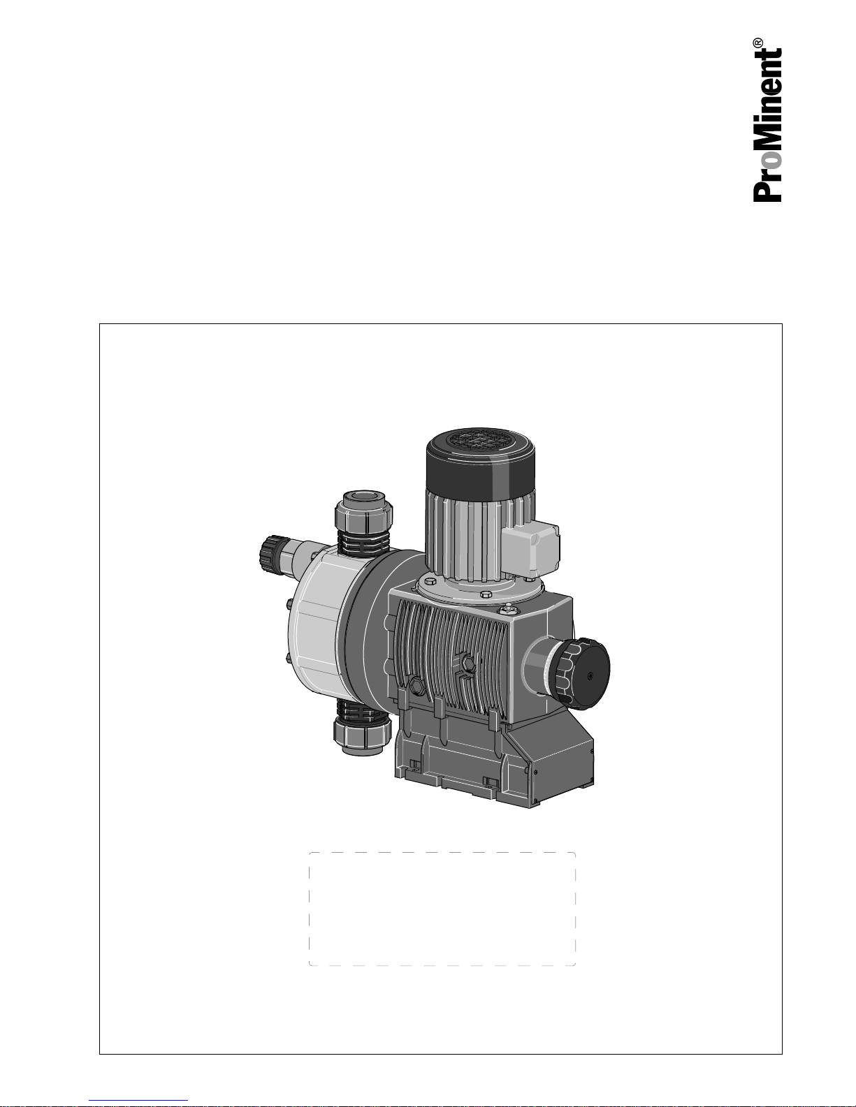
Diaphragm motor-driven metering pump
Sigma/ 3 Basic type S3Ba
Operating instructions
P_SI_0075_SW
EN
Original operating instructions (2006/42/EC)Part no. 985905 BA SI 089 01/19 EN
Please carefully read these operating instructions before use. · Do not discard.
The operator shall be liable for any damage caused by installation or operating errors.
The latest version of the operating instructions are available on our homepage.
Page 2

Read the following supplementary information in its entirety! Should you
already know this information, you will benefit more from referring to the
operating instructions.
The following are highlighted separately in the document:
n Enumerated lists
Operating guidelines
ð
Outcome of the operating guidelines
- see (reference)
Information
This provides important information relating to the cor‐
rect operation of the unit or is intended to make your
work easier.
Safety notes
Safety notes are identified by pictograms - see Safety Chapter.
These operating instructions conform to current EU regulations applicable
at the time of publication.
Please state identity code and serial number, which you can find on the
nameplate when you contact us or order spare parts. This enables the
device type and material versions to be clearly identified.
Supplementary information
Fig. 1: Please read!
Validity
State the identity code and serial number
Supplemental directives
2
Page 3

Table of contents
1
Identity code.................................................................................... 5
1.1 Explanation of the ATEX label................................................ 6
2 Safety chapter................................................................................. 9
2.1 Safety information for ATEX designs.................................... 15
2.2 Explanation of the ATEX label.............................................. 23
3 Storage, Transport and Unpacking................................................ 26
4
Overview of equipment and control elements............................... 27
5 Functional description.................................................................... 29
5.1 Pump..................................................................................... 29
5.2 Liquid end.............................................................................. 29
5.3 Integral relief valve................................................................ 29
5.4 Multi-layer safety diaphragm................................................. 30
6 Assembly....................................................................................... 31
7 Installation, hydraulic..................................................................... 34
7.1 Basic installation notes.......................................................... 38
8 Installation, electrical..................................................................... 39
9 Start up.......................................................................................... 46
10 During operation............................................................................ 50
11 Maintenance.................................................................................. 51
12 Carrying out repairs....................................................................... 56
12.1 Cleaning valves................................................................... 57
12.2 Replacing the diaphragm.................................................... 58
13 Troubleshooting............................................................................. 62
14
Decommissioning.......................................................................... 65
15 Technical data............................................................................... 68
15.1 Performance data................................................................ 68
15.2 Shipping weight................................................................... 69
15.3 Wetted materials................................................................. 70
15.4 Ambient conditions.............................................................. 70
15.4.1 Ambient temperatures...................................................... 70
15.4.2 Media temperatures......................................................... 70
15.4.3 Air humidity...................................................................... 71
15.5 Installation height................................................................ 71
15.6 Motor data........................................................................... 72
15.7 Stroke actuator.................................................................... 73
15.8 Stroke control drive............................................................. 73
15.9 Diaphragm rupture sensor.................................................. 73
15.10 Stroke sensor "Sigma"...................................................... 74
15.11 Relay................................................................................. 74
15.12 Gear oil.............................................................................. 75
15.13 Sound pressure level........................................................ 75
15.14 Supplementary information for modified versions............. 75
16 Diagrams for setting the metering capacity................................... 76
17
Dimensional drawings................................................................... 77
18 Potential equalisation drawings for Sigma Basic Type.................. 82
19 Motor data sheet standard motor.................................................. 84
20 Exploded drawings of Sigma/ 3..................................................... 85
21 Wear parts of Sigma/ 3.................................................................. 92
21.1 Standard.............................................................................. 92
Table of contents
3
Page 4

21.2 Physiological safety............................................................. 92
22 Declaration of Conformity for Machinery....................................... 94
23
Declaration of Incorporation for Machinery.................................... 95
24 Declaration of Conformity for ATEX Machinery............................. 96
25 Declaration of Conformity for ATEX Machinery............................. 97
26 Index.............................................................................................. 98
Table of contents
4
Page 5

1 Identity code
S3Ba Sigma 3 Basic type
H Main power end, diaphragm
Type: Capacity
_ _ _ _
_ _
Performance data at maximum back pressure: see nameplate on pump housing
Dosing head material
PP Polypropylene
PC PVC
PV PVDF
TT PTFE + carbon
SS Stainless steel
Seal material
T PTFE seal
Displacement body
S Multi-layer safety diaphragm with optical rupture indicator
A Multi-layer safety diaphragm with diaphragm rupture signalling (contact)
H Diaphragm for hygienic head (on request)
Dosing head design
0 no valve springs
1 with 2 valve springs, Hastelloy C; 0.1 bar (standard with DN 32)
4 with relief valve, FPM seal, no valve springs
5 with relief valve, FPM seal, with valve springs (standard with DN 32)
6 with relief valve, EPDM seal, no valve spring
7 with relief valve, EPM seal, with valve spring (standard with DN 32)
H Hygienic head with tri-clamp connectors (max. 10 bar) (on request)
Hydraulic connector
0 Standard threaded connector (in line with technical data)
1 Union nut and PVC insert
2 Union nut and PP insert
3 Union nut and PVDF insert
4 Union nut and SS insert
7 Union nut and PVDF hose nozzle
8 Union nut and SS hose nozzle
9 Union nut and SS welding sleeve
Design
0
with ProMinent® logo
1
without ProMinent®
logo
F Physiological safety with
regard to wetted mate‐
rials
FDA No. 21 CFR §177.1550
(PTFE)
FDA No. 21 CFR §177.2510
(PVDF)
Identity code
5
Page 6

S3Ba Sigma 3 Basic type
M modified* * order-related design, refer to
order paperwork for pump
features
Electric power supply
_ Connection data - see motor nameplate
1 no motor, with B 5 flange, size 80 (DIN)
2 no motor, with C 56 flange (NEMA)
3 no motor, with B 5, size 71 (DIN)
Degree of protection
0 IP 55 (standard)
1 Exe design ATEX-T3 ***
2 Exd design ATEX-T4 ***
Stroke sensor
0 no stroke sensor (standard)
2 pacing relay (reed relay)
3 stroke sensor (Namur) for areas at
risk from explosion
Stroke length adjustment
0 manual (standard)
1, 2 Connection data - refer to
nameplate on servomotor
3 - 6 Connection data - refer to
nameplate on stroke control
motor
*** ATEX specification - refer to the nameplate on the pump, corre‐
sponding EU Declaration of Conformity for ATEX Machinery and
Ä Chapter 1.1 ‘Explanation of the ATEX label’ on page 6
FPM = fluorine rubber
1.1 Explanation of the ATEX label
in accordance with Directive 2014/34/EU and standards EN ISO
80079-36, -37
Unit group
II Units for use in areas with a potentially explosive atmosphere – excluding mines
Unit category
2 High level of safety – use possible in zones 1 and 2
3 Normal level of safety – use possible in zone 2
Identity code
6
Page 7

Type of explosive atmosphere
G Mix of air and gases, vapours or mist
Areas at risk of explosion label
Ex in accordance with EN ISO 80079-36, -37
Type of protection
h non-electrical device
Explosion group
IIC
Group IIC gas - refer, for example, to
Ä Tab. 1 ‘Divi‐
sion of gases into explosion groups and temperature
classes’ on page 7
IIB
Group IIB gas - for example
Ä Tab. 1 ‘Division of
gases into explosion groups and temperature classes’
on page 7
Temperature class
T3 Max. surface temperature: 200 °C
T4 Max. surface temperature: 135 °C
Equipment protection level (EPL)
Gb high EPL in normal operation and in
the event of expected errors (corre‐
sponds to category “2G”.)
Gc normal EPL in normal operation (corre‐
sponds to category “3G”.)
Suffix X
X Special conditions - refer to the
Declarations of Conformity and
EC-type examination certifi‐
cates
Tab. 1: Division of gases into explosion groups and temperature classes
T4 T3 T2 T1
IIC - - Acethylene Hydrogen
IIB Ethyl ether - Ethylene Mains gas (coal gas)
IIA Acetaldehyde Benzine,
Diesel fuel,
Aircraft fuel,
Heating oils,
n-hexane
Ethyl alcohol,
n-butane,
n-butyl alcohol
Acetone,
Ammonia,
Benzene (pure),
Acetic acid,
Ethane,
Ethyl acetate,
Carbon oxide,
Methanol,
Propane,
Toluene
Identity code
7
Page 8

You should always consider the explosion group AND
temperature class together:
You are safe in areas at risk from explosion with all the
gases listed in the table with equipment approved for
explosion group IIC and temperature class T4.
Equipment approved for explosion group IIB can also be
used for explosion group IIA – not for explosion group
IIC.
Equipment approved for temperature class T3 can also
be used for temperature classes T2 to T1 – not for tem‐
perature class T4.
Identity code
8
Page 9

2 Safety chapter
CAUTION!
These operating instructions include notes and extracts
from German regulations relating to the operator's scope
of responsibility. This information does not discharge the
operator from his responsibility as an operator and is
intended only to remind him or make him aware of spe‐
cific problem areas. This information does not lay claim
to being complete, nor applicable to every country and
every type of application, nor to being unconditionally
up-to-date.
The following signal words are used in these operating instructions to
denote different severities of danger:
Signal word Meaning
WARNING Denotes a possibly dangerous sit‐
uation. If this is disregarded, you
are in a life-threatening situation
and this can result in serious inju‐
ries.
CAUTION Denotes a possibly dangerous sit‐
uation. If this is disregarded, it
could result in slight or minor inju‐
ries or material damage.
The following warning signs are used in these operating instructions to
denote different types of danger:
Warning signs Type of danger
Warning – high-voltage.
Warning – danger zone.
n Only use the pump to meter liquid feed chemicals.
n Only pumps with the identity code option "Multi-layer safety diaphragm
with visual rupture display" and "Multi-layer safety diaphragm with rup‐
ture signalling (contact)" are approved for use with flammable feed
chemicals with electrically conductive dosing heads, at back pres‐
sures of over 2 bar and only if the operator takes appropriate safety
measures.
n Only pumps with the design "F - Physiologically safe with regard to
wetted materials" are approved for use in physiologically harmless
applications.
n Only “H - Hygienic head” design pumps may be used for applications
in accordance with the hygienic requirements of the EHEDG
(www.ededg.org).
n The pump may only be started up after it has been correctly installed
and started up in accordance with the technical data and specifica‐
tions contained in the operating instructions.
n Observe the general limitations with regard to viscosity limits, chem‐
ical resistance and density - see also the ProMinent Resistance List
(in the Product Catalogue or at www.prominent.com)!
n All other uses or modifications are prohibited.
Identification of safety notes
Warning signs denoting different types of
danger
Intended use
Safety chapter
9
Page 10

n The pump is not intended for the metering of gaseous media and
solids.
n The pump is not intended for the metering of explosive substances
and mixtures.
n The pump is not intended for unprotected use outdoors.
n The pump is only intended for industrial use.
n Only allow trained and authorised personnel to operate the pump -
see the following table.
n You have a responsibility to adhere to the information contained in the
operating instructions at the different phases of the unit's service life.
n You have a responsibility to observe the information contained in the
operating instructions for the auxiliary equipment at the different
phases of their respective service lives.
n ATEX designs only: Refer to the chapter "
Ä Chapter 2.1 ‘Safety infor‐
mation for ATEX designs’ on page 15
".
Task Qualification
Storage, transport, unpacking Instructed person
Assembly Technical personnel, service
Planning the hydraulic installation Qualified personnel who have a
thorough knowledge of oscillating
diaphragm pumps
Hydraulic installation Technical personnel, service
Electrical installation Electrical technician
Start up Technical personnel
Operation Instructed person
Maintenance, repair Technical personnel, service
Decommissioning, disposal Technical personnel, service
Troubleshooting Qualified person, electrical techni‐
cian, instructed person, service depending on the requirement
Explanation of the table:
Trained, qualified personnel
A trained, qualified employee is deemed to be a person who is able to
assess the tasks assigned to him and recognise possible hazards based
on his training, knowledge and experience, as well as knowledge of perti‐
nent regulations. A trained, qualified employee must be able to perform
the tasks assigned to him/her independently with the assistance of
drawing documentation and parts lists. The assessment of a person's
technical training can also be based on several years of work in the rele‐
vant field.
Electrical technician
An electrical technician is able to complete work on electrical systems and
recognise and avoid possible dangers independently based on his tech‐
nical training and experience as well as knowledge of pertinent standards
and regulations. An electrical technician must be able to perform the tasks
assigned to him/her independently with the assistance of drawing docu‐
mentation, parts lists, terminal and circuit diagrams. The electrical techni‐
cian must be specifically trained for the working environment in which the
electrical technician is employed and be conversant with the relevant
standards and regulations.
Instructed person
An instructed person is deemed to be a person who has been instructed
and, if required, trained in the tasks assigned to him/her and possible dan‐
gers that could result from improper behaviour, as well as having been
instructed in the required protective equipment and protective measures.
Qualification of personnel
Safety chapter
10
Page 11

Trained user
A trained user is a person who fulfils the requirements demanded of an
instructed person and who has also received additional training specific to
the system from ProMinent or another authorised distribution partner.
Service
The Service department refers to service technicians, who have received
proven training and have been authorised by ProMinent to work on the
system.
Ignition hazard Protective measures to be observed by the customer
Excessive surface pressure Limitation of the maximum temperature of the feed chem‐
ical
Too low ambient temperature Limitation of the minimum ambient temperature
Pump running hot The customer must monitor and maintain the pump in
accordance with the “Maintenance” chapter.
The customer must fit a relief valve on the discharge side.
Mechanically generated sparks from the mechanism with
low oil
The customer must monitor and maintain the pump in
accordance with the “Maintenance” chapter.
Mechanically generated sparks from a faulty valve The customer must monitor the capacity.
Electrical stray current in the event of a short circuit The customer must earth the pump and maintain the
earthing of the individual components.
Electrical stray current in the event of a lightning strike The customer must put in place suitable protective meas‐
ures outdoors.
Static electricity The customer must earth the earthing points and maintain
the potential equalisation cables of the individual compo‐
nents.
The customer must pay attention to potential equalisation
when dismantling.
Paint should not be applied too thickly.
Only clean plastic parts with a damp cloth.
Provide a temperature monitor on the dosing head with
feed chemical with critical friction properties.
The customer must wire the diaphragm rupture indicator in
such a way that it immediately stops the pump.
Electromagnetic waves (also lasers), ionising radiation
and ultrasound have an impact on the pump
The customer must put in place measures in accordance
with EN 1127-1, if need be.
Adiabatic compression and shock waves Feed chemical with electrical conductivity of < 50 pS/m,
which could form a combustible mixture: Do not allow the
unit to run dry – even when filling and emptying the liquid
end.
Exothermic reaction, including the self-combustion of dust The pump is not suitable for use with substances that
have a tendency towards exothermic reactions or selfcombustion. Put in place measures in accordance with EN
1127-1, if need be.
Deposits of dust Regularly clean the outside of the pump with a damp
cloth.
Summary of relevant ignition hazards and
protective measures put in place for the
Sigma in accordance with EN ISO
80079-36
Safety chapter
11
Page 12

Ignition hazard Protective measures to be observed by the customer
Flammable feed chemicals Only material version SS or TT is permitted to pump flam‐
mable feed chemicals.
Do not allow it to run dry.
The operator must install suitable protective measures, for
example a flow meter.
The customer must wire the diaphragm rupture indicator in
such a way that it immediately stops the pump.
Ignition hazard with bought-in motor components Refer to the documentation for the motor.
Comply with the monitoring intervals.
The insulation resistance needs to be greater then 5
MOhm.
Provide a time-delay residual current device.
Provide overload protection by means of a motor protec‐
tion switch or an equivalent protective device.
Observe the minimum spacing between the air inlet on the
fan hood and any obstacles.
Avoid deposits of dust more then 5 mm deep.
Connect the earth wire.
Max. installation height: 1,000 m.a.s.l.
Ignition hazard with bought-in actuator or control drive
components
Refer to the documentation for the actuator.
Wait 3 minutes after switching off before opening the
housing.
Ignition hazard caused by bought-in proximity switch
NJ1.5-8GM-N (stroke sensor)
Refer to the documentation for the proximity switch (elec‐
trical installation, maintenance, ...).
WARNING!
Warning of hazardous feed chemical
Should a dangerous feed chemical be used: it may
escape from the hydraulic components when working on
the pump, material failure or incorrect handling of the
pump.
– Take appropriate protective measures before
working on the pump (e.g. safety glasses, safety
gloves, ...). Adhere to the material safety data sheet
for the feed chemical.
–
Drain and flush the liquid end before working on the
pump.
Safety information
Safety chapter
12
Page 13

WARNING!
Danger from hazardous substances!
Possible consequence: Fatal or very serious injuries.
Please ensure when handling hazardous substances
that you have read the latest safety data sheets provided
by the manufacture of the hazardous substance. The
actions required are described in the safety data sheet.
Check the safety data sheet regularly and replace, if
necessary, as the hazard potential of a substance can
be re-evaluated at any time based on new findings.
The system operator is responsible for ensuring that
these safety data sheets are available and that they are
kept up to date, as well as for producing an associated
hazard assessment for the workstations affected.
CAUTION!
Warning of feed chemical spraying around
Feed chemical can spray out of the hydraulic compo‐
nents if they are manipulated or opened due to pressure
in the liquid end and adjacent parts of the system.
– Disconnect the pump from the mains power supply
and ensure that it cannot be switched on again by
unauthorised persons.
– Depressurise the system before commencing any
work on hydraulic parts.
CAUTION!
Warning of feed chemical spraying around
An unsuitable feed chemical can damage the parts of
the pump that come into contact with the chemical.
– Take into account the resistance of the wetted mate‐
rials and the ProMinent Resistance List when
selecting the feed chemical - see the ProMinent
Product Catalogue or visit ProMinent.
WARNING!
Danger of injury to personnel and material damage
The pump must only be opened at those points required
to be opened by these operating instructions.
It may only be opened in other positions upon receipt of
written authorisation from the ProMinent head office,
Heidelberg.
CAUTION!
Danger of personnel injury and material damage
The use of untested third party parts can result in per‐
sonnel injuries and material damage.
– Only fit parts to metering pumps, which have been
tested and recommended by ProMinent.
Safety chapter
13
Page 14

CAUTION!
Danger from incorrectly operated or inadequately main‐
tained pumps
Danger can arise from a poorly accessible pump due to
incorrect operation and poor maintenance.
– Ensure that the pump is accessible at all times.
–
Adhere to the maintenance intervals.
In the event of an electrical accident, disconnect the mains cable from the
mains or press the emergency cut-off switch fitted on the side of the
system!
If feed chemical escapes, also depressurise the hydraulic system around
the pump as necessary. Adhere to the safety data sheet for the feed
chemical.
Prior to commissioning the system or system component, it is the respon‐
sibility of the system operator to obtain the latest safety data sheet for the
chemicals / equipment to be used with the system from the supplier.
Based on the information provided in the data sheets concerning health
and safety, water and environmental protection, and taking into considera‐
tion the actual operating environment on site, it is the responsibility of the
operator to create the legal framework for the safe operation of the system
or system component, such as for example the preparation of operating
instructions (operator's duties).
All isolating protective equipment must be installed for operation:
Protective equipment May only be removed by*:
Motor terminal box cover Electrical technician, ATEX elec‐
trical technician, Service
Protective cowling over the motor
fan
Service
Power end front cover Service
* Only if required by the operating instructions and if the mains cable
remains disconnected from the mains voltage.
The operator must be able to:
n Perform a risk assessment
n Produce and attach a nameplate
n Issue a Declaration of Conformity
n Adapt the operating instructions, if necessary
n Install the motor correctly
1. Select a suitable motor - it must correspond to the data for one of
the motors from the "Motor data" table - see Chapter "Technical
data"
2. Fit the motor correctly on the flange (qualified personnel).
Information in the event of an emergency
Safety information for operating instruc‐
tions
Safety equipment
Isolating protective equipment
Requirements if the motor is being
installed independently
Install the motor - with designs without
motor
Safety chapter
14
Page 15

3. As you have converted an "incomplete machine" into a complete
machine, you must perform a conformity assessment, risk assess‐
ment, create a Declaration of Conformity, fit a company name‐
plate, ... .
4. Complete the pump documentation / operating instructions.
Sound pressure level LpA < 70 dB according to EN ISO 20361
at maximum stroke length, maximum stroke rate, maximum back pressure
(water)
2.1
Safety information for ATEX designs
This chapter lists all safety information for ATEX designs. Safety informa‐
tion is listed again at the relevant points in these operating instructions.
This safety information is supplementary to or replaces the safety informa‐
tion for non-ATEX designs. If the safety information for ATEX designs con‐
tradicts the other safety information, then the safety information in this
chapter applies to ATEX designs.
n Only operate an ATEX design pump in premises at risk from explosion
in accordance with the applicable guidelines.
n Do not expose the ATEX design to any sources of ionising radiation or
electromagnetic high frequency radiation in the range 104 ... 3x10¹⁵ Hz
or laser radiation or ultrasound or lightning without putting in place
measures in line with EN 80079-38.
n Do not allow the ATEX design to meter media, which tends to produce
exothermic reactions or self-ignite (examples of exothermic reactions:
pyrophoric substances with air, alkali metal with water, decomposition
of organic peroxides, polymerisation reactions), without taking effec‐
tive measures in accordance with EN 80079-38.
Task Qualification
Planning the hydraulic installation ATEX qualified person, ATEX elec‐
trical technician
Electrical installation ATEX electrical technician
Start up Skilled ATEX technician;
Checking the electrical installation:
Recognised competent person
Maintenance, repair ATEX qualified person, ATEX elec‐
trical technician
Troubleshooting Qualified ATEX technician or ATEX
electrical technician - depending on
the fault;
Checking the electrical installation:
Recognised competent person
Explanation of the table:
Recognised competent person
To carry out explosion hazard inspections the competent person must
have:
n Completed a relevant course of study or
n Have a comparable technical qualification or
n Another technical qualification combined with long-term experience of
safety technology.
Sound pressure level
Intended use
Qualification of personnel
Safety chapter
15
Page 16

Make sure that the person is familiar with the relevant body of standards
and regulations and has worked in the field for at least one year. The
person needs to have opportunities for an exchange of experiences.
Specific requirements are placed on competent persons who perform tests
on repaired devices/parts. They must be recognised by the responsible
authorities (e.g. district council) in this respect.
Skilled technician with knowledge of ATEX explosion protection
The skilled technician with an additional explosion protection qualification
should be specifically trained for the work area in which he is employed
and be familiar with the relevant standards and regulations. The skilled
technician with an additional explosion protection qualification can work on
equipment and systems in areas protected from explosion and independ‐
ently recognise and avoid possible dangers based on his technical training
and experience.
The skilled technician with an additional explosion protection qualification
is familiar with all the standards and regulations applicable to explosion
protection.
The skilled technician with an additional explosion protection qualification
must comply with the provisions of the applicable statutory directives on
accident prevention.
Electrical technician with knowledge of ATEX explosion protection
An electrical technician with an additional explosion protection qualification
should be specifically trained for the field of work in which he is employed
and be familiar with the relevant standards and regulations. An electrical
technician with an additional explosion protection qualification can work on
electrical systems and independently recognise and avoid possible dan‐
gers based on his technical training and experience.
The electrical technician with an additional explosion protection qualifica‐
tion is familiar with all the standards and regulations applicable to explo‐
sion protection.
An electrical technician with an additional explosion protection qualification
must comply with the provisions of the applicable statutory directives on
accident prevention.
Recognised competent person
To carry out explosion hazard inspections the competent person must
have:
n Completed a relevant course of study or
n Have a comparable technical qualification or
n Another technical qualification combined with long-term experience of
safety technology.
Make sure that the person is familiar with the relevant body of standards
and regulations and has worked in the field for at least one year. The
person needs to have opportunities for an exchange of experiences.
Specific requirements are placed on competent persons who perform tests
on repaired devices/parts. They must be recognised by the responsible
authorities (e.g. district council) in this respect.
Ignition hazard Protective measures to be observed by the customer
Excessive surface pressure Limitation of the maximum temperature of the feed chem‐
ical
Too low ambient temperature Limitation of the minimum ambient temperature
Pump running hot The customer must monitor and maintain the pump in
accordance with the “Maintenance” chapter.
The customer must fit a relief valve on the discharge side.
Summary of relevant ignition hazards and
protective measures put in place for the
Sigma in accordance with EN ISO
80079-36
Safety chapter
16
Page 17

Ignition hazard Protective measures to be observed by the customer
Mechanically generated sparks from the mechanism with
low oil
The customer must monitor and maintain the pump in
accordance with the “Maintenance” chapter.
Mechanically generated sparks from a faulty valve The customer must monitor the capacity.
Electrical stray current in the event of a short circuit The customer must earth the pump and maintain the
earthing of the individual components.
Electrical stray current in the event of a lightning strike The customer must put in place suitable protective meas‐
ures outdoors.
Static electricity The customer must earth the earthing points and maintain
the potential equalisation cables of the individual compo‐
nents.
The customer must pay attention to potential equalisation
when dismantling.
Paint should not be applied too thickly.
Only clean plastic parts with a damp cloth.
Provide a temperature monitor on the dosing head with
feed chemical with critical friction properties.
The customer must wire the diaphragm rupture indicator in
such a way that it immediately stops the pump.
Electromagnetic waves (also lasers), ionising radiation
and ultrasound have an impact on the pump
The customer must put in place measures in accordance
with EN 1127-1, if need be.
Adiabatic compression and shock waves Feed chemical with electrical conductivity of < 50 pS/m,
which could form a combustible mixture: Do not allow the
unit to run dry – even when filling and emptying the liquid
end.
Exothermic reaction, including the self-combustion of dust The pump is not suitable for use with substances that
have a tendency towards exothermic reactions or selfcombustion. Put in place measures in accordance with EN
1127-1, if need be.
Deposits of dust Regularly clean the outside of the pump with a damp
cloth.
Flammable feed chemicals Only material version SS or TT is permitted to pump flam‐
mable feed chemicals.
Do not allow it to run dry.
The operator must install suitable protective measures, for
example a flow meter.
The customer must wire the diaphragm rupture indicator in
such a way that it immediately stops the pump.
Ignition hazard with bought-in motor components Refer to the documentation for the motor.
Comply with the monitoring intervals.
The insulation resistance needs to be greater then 5
MOhm.
Provide a time-delay residual current device.
Provide overload protection by means of a motor protec‐
tion switch or an equivalent protective device.
Observe the minimum spacing between the air inlet on the
fan hood and any obstacles.
Avoid deposits of dust more then 5 mm deep.
Connect the earth wire.
Max. installation height: 1,000 m.a.s.l.
Safety chapter
17
Page 18

Ignition hazard Protective measures to be observed by the customer
Ignition hazard with bought-in actuator or control drive
components
Refer to the documentation for the actuator.
Wait 3 minutes after switching off before opening the
housing.
Ignition hazard caused by bought-in proximity switch
NJ1.5-8GM-N (stroke sensor)
Refer to the documentation for the proximity switch (elec‐
trical installation, maintenance, ...).
WARNING!
ATEX pumps in areas at risk from explosion
– The operator must observe the Operator Directive
when operating equipment in areas at risk of explo‐
sion.
–
Only clean plastic parts carefully with a damp cloth
to avoid electrostatic charges and sparks.
WARNING!
Motor may overheat
If the necessary cooling air supply is not guaranteed, the
motor may overheat. In an area at risk from explosion, it
could trigger an explosion.
– Maintain sufficient clearance between the air intake
opening and the walls. The distance should be
greater than 1/4 of the diameter of the air intake
opening.
–
The fan must not suck in the exhaust air from other
devices.
WARNING!
ATEX pumps in areas at risk from explosion
– Metering pumps must have an appropriate safety
relief valve on the discharge side (to protect against
excessive heating due to overloading or impact
sparks caused by the breakage of power end parts).
WARNING!
ATEX pumps in areas at risk from explosion
– A flow control is needed to stop the pump as soon
as no flow is detected.
WARNING!
ATEX pumps and flammable media
Only with material versions PP_, PV_ and PC_: The igni‐
tion temperature is reduced significantly below the igni‐
tion temperature at atmospheric pressure due to com‐
pression with the discharge stroke of the possibly
ignitable vapour-air mixture.
– Do not allow it to run dry. Take appropriate protec‐
tive measures.
–
Immediately switch off the pump in the event of a
diaphragm rupture.
Safety information
Safety chapter
18
Page 19

WARNING!
ATEX pumps in areas at risk from explosion
If feed chemicals are metered, which tend to produce
exothermic reactions or self-ignite (examples of exo‐
thermic reactions: pyrophoric substances with air, alkali
metal with water, decomposition of organic peroxides,
polymerisation reactions), they can lead to high tempera‐
tures and ignition.
– Put in place measures in accordance with EN
80079-38.
WARNING!
ATEX pumps in areas at risk from explosion
If abrasive media is being metered, it will escape as
soon as all layers of the diaphragm have eroded
through.
– Wire the electrical diaphragm rupture indicator to
stop the pump in the event of a diaphragm rupture.
WARNING!
ATEX pumps in areas at risk from explosion
– Electrically wire all electrical units cleanly and per‐
manently to an electrically clean earthing point, e.g. with an earthing bar on your system.
–
Electrically connect the electrical units fitted with a
potential equalisation cable to each other, cleanly
and permanently, to an electrically clean potential
equalisation point - e.g. with a potential equalisation
bar on your system.
– Note the enclosed documentation for the individual
electrical components.
WARNING!
ATEX pumps in areas at risk from explosion
– Use a suitable motor protection switch to protect
power end motors. Use motor protection approved
for this application with Ex"e" motors. (Protection
against warming caused by overloading)
–
Provide a time-delay residual current device.
– Observe the enclosed operating instructions for the
Ex motor.
WARNING!
The following applies in areas at risk from explosion:
– Note the details of the type examination certificate
PTB 00 ATEX 2048 X for the Namur sensor
NJ1.5-8GM-N as well.
Safety chapter
19
Page 20

WARNING!
ATEX pumps in areas at risk from explosion
– Make sure that a suitably competent person checks
whether the appropriate installation information from
the "Installation" chapter has been implemented cor‐
rectly.
–
Make sure that a "recognised competent person"
checks the electrical installation and in particular the
intrinsically safe power circuits.
– Set the opening pressure of the relief valve to a
maximum of no more than 1.5 times the nominal
pressure of the pump.
WARNING!
ATEX pumps in areas at risk from explosion
– Carry out a general check to ensure that the system
is working properly, particularly the power end and
bearings, by regularly monitoring it (for leaks,
noises, temperatures, smell, etc.).
– Do not allow the pump to run hot due to a lack of oil.
With lubricated metering pumps, regularly check for
the presence of lubricant, for example by checking
the liquid level, visual leak control etc. If oil is
leaking, examine the leakage point immediately and
eliminate the cause.
– Check the correct operation of the relief valve down‐
stream of the pump. In premises at risk from explo‐
sion, the relief valve should prevent the gear from
becoming overloaded and becoming hot.
– Observe the enclosed operating instructions for the
Ex motor.
– Only use a moist cloth when cleaning plastic parts.
– Prevent serious deposits of dust on the motor.
– Consider potential equalisation before you approach
any pump equipment that could be at a different
electrical potential (such as pipes or tools).
– Replace wear parts, such as bearings, when there is
an identifiable incidence of unacceptable wear.
– Appropriate diagnostic equipment for bearing
damage is recommended for the premature detec‐
tion of bearing damage.
– Check whether the potential equalisation lines are
all sitting correctly with clean contacts. Use the equi‐
potential bonding drawings as an aid – see
Appendix.
– Check whether the earth lines are all sitting correctly
with clean contacts. Use the equipotential bonding
drawings as an aid – see Appendix.
– Only use genuine spare parts as replacements.
The entire installation supplied is provided ex works with the necessary
potential equalisation lines.
Electrically wire an additional potential equalisation cable from the poten‐
tial equalisation cables from this system cleanly and permanently to an
electrically clean potential equalisation point, e.g. to a potential equalisa‐
tion bar on site.
Potential equalisation of frame
An earthing point for the customer is fitted on the frame.
Potential equalisation line (prescribed in
the area at risk from explosion)
Safety chapter
20
Page 21

When a frame is used, a motor screw is factory-connected by a protective
earth cable to the earthing point.
5–25 V DC, in accordance with Namur or DIN 19234, potential-free
design.
Data Value Unit
Rated voltage * 8 VDC
Power consumption - active surface
uncovered
> 3 mA
Power consumption - active surface cov‐
ered
< 1 mA
Rated switching distance 1.5 mm
* Ri ~ 1 kΩ
Cable colour Polarity
blue -
brown +
Install the sensor in accordance with the chapter "Instal‐
lation, electrical". Refer to its documentation.
Sensor name: NJ1.5-8GM-N.
Changing the motor voltage and pulse frequency is not permitted.
The motors can be operated within a frequency range of 2 Hz (limited
torque) to 100 Hz.
The pulse frequency of the frequency converter is 4 kHz.
Check the pump installation for:
n Leaks
n Abnormal noises or squeaks
n Abnormal temperatures
n Abnormal odours
n Abnormal vibrations
n Other anomalies
WARNING!
Stop the pump immediately in the event of any anoma‐
lies when inspecting the pump and rectify them immedi‐
ately. ProMinent Service may be needed if required.
Interval Maintenance work
After 18,000 operating hours or 23,500 oper‐
ating hours (API)
Adhere to the motor manufacturer's recommendations - see oper‐
ating instructions for the motor.
After 40,000 h: The upper screw shaft bearing must be replaced for
ongoing ATEX use.
Namur sensor (Specified for EX zones)
Motor design V2 (motor with integrated
frequency converter)
Inspection, daily
Maintenance
Safety chapter
21
Page 22

Screw in the oil drainage plug (2) with a new seal.
WARNING!
Check after 1 day whether the oil drainage plug (2) is still
tight.
Data Value Unit
Ambient temperature during operation: -10 ... +40 °C
Data Value Unit
Max. temperature, long-term at max. oper‐
ating pressure
50 °C
Minimum temperature. -10 °C
Data Value Unit
Max. temperature, long-term at max. oper‐
ating pressure
50 °C
Minimum temperature. -10 °C
Data Value Unit
Max. temperature, long-term at max. oper‐
ating pressure
90 °C
Minimum temperature. -10 °C
Data Value Unit
Maximum installation height*: 1000 m above
standard
zero
* We urgently advise you to contact a specialist for ATEX motors with
higher intended installation heights!
WARNING!
– The following safety information must be affixed to
pumps that include parts made of electrically non-
conducting plastic.
–
Ensure that the label is always fitted and legible.
– Do not allow other labels to be stuck over this label.
Power end and motor – ATEX
PPT - ATEX liquid end
TTT - ATEX liquid end
SST - ATEX liquid end
Installation height
Safety equipment
Other safety equipment - ATEX labels
Safety chapter
22
Page 23
electrostatic charging hazard
- see instructions
Potential
W a r n i n g
Fig. 2
The operator must be able to:
n with ATEX motors: perform an ignition hazard assessment
1. Select a suitable motor - it must correspond to the data for one of
the motors from the "Motor data" table - see Chapter "Technical
data".
WARNING!
EX is relevant in areas at risk from explosion!
2. Fit the motor correctly on the flange (qualified personnel).
Observe the coupling operating instructions!
WARNING!
EX is relevant in areas at risk from explosion!
With a claw coupling: The claw on the motor shaft must be fixed at
the correct height, see corresponding figure and table.
3. As you have converted an "incomplete machine" into a complete
machine, you must perform a conformity assessment, risk assess‐
ment, issue an EC Declaration of Conformity, fit your own company
nameplate, ... .
4. With ATEX pumps: additionally perform an ignition hazard assess‐
ment.
5. Complete the pump documentation / operating instructions.
Refer to the end of the operating instructions for the Declaration of Con‐
formity for the pump.
If there is an “X” at the end of the ATEX specification of a unit in a “Decla‐
ration of Conformity for ATEX Machines” or a “Declaration of Incorporation
for ATEX Machines”, then special conditions apply for the safe operation
of the equipment in areas at risk from explosion.
Please refer in this respect to the operating instructions, design test certifi‐
cates and other documentation for the bought-in parts!
2.2 Explanation of the ATEX label
in accordance with Directive 2014/34/EU and standards EN ISO
80079-36, -37
Requirements if the motor is being
installed independently
Install the motor - with designs without
motor
Declarations of Conformity for the pump
Special conditions X
Safety chapter
23
Page 24

Explanation of the pump’s ATEX labelling Sigma S3Ba
Unit group
II No mines or associated underground systems, which can be endangered by firedamp - Unit for use in
other areas at risk from explosion
Other parameters
3G Ex h (Example)
Explosion group
IIC for Group IIC gas
- Refer to the material safety data sheet for the gas or, for example,
Ä Tab. 2 ‘Example of the division of gases into explosion groups and temperature
classes’ on page 25
IIB for Group IIB gas
- Refer to the material safety data sheet for the gas or, for example,
Ä Tab. 2 ‘Example of the division of gases into explosion groups and temperature
classes’ on page 25
Temperature class
T3 for Temperature class T3 gas
- Refer to the material safety data sheet for the gas or, for example,
Ä Tab. 2 ‘Example of the division of gases into explosion groups and
temperature classes’ on page 25
T4 for Temperature class T4 gas
- Refer to the material safety data sheet for the gas or, for example,
Ä Tab. 2 ‘Example of the division of gases into explosion groups and
temperature classes’ on page 25
Equipment protection level (EPL)
Gb high EPL in normal operation and in the event of expected errors;
use possible in zones 1 and 2
- refer to your explosion protection document
Gc normal EPL in normal operation;
use possible in zone 2
- refer to your explosion protection document
Suffix X
X Special conditions - refer to the Declarations of Conformity
and EC-type examination certificates
Safety chapter
24
Page 25

WARNING!
Example: Where may I use the ATEX pump Sigma
S3Ba?
The pump label corresponds to “Unit group” II: the pump
may only be used in overground production systems,
which are not at risk from firedamp.
The pump label states e.g. “Explosion group” IIB and
“Temperature class” T4:
Ä Tab. 2 ‘Example of the division of gases into explo‐
sion groups and temperature classes’ on page 25
shows the following example: the pump can be used for
ethyl ether or a comparable substance - the “Explosion
group” and “Temperature class” are stated in the mate‐
rial safety data sheets for the substances. The pump in
the example could also be suitable for substances that
require only “Explosion group” IIA and / or “Temperature
class” T3, T2 or T1.
The pump label is e.g. “EPL” Gc: the potentially explo‐
sive atmosphere may only occur in normal operation.
Tab. 2: Example of the division of gases into explosion groups and temperature classes
T4 T3 T2 T1
IIC - - Ethyne Hydrogen
IIB Ethyl ether - Ethene Mains gas (coal gas)
IIA Acetaldehyde Benzine,
Diesel fuel,
Aircraft fuel,
Heating oils,
n-hexane
Ethanol,
n-butane,
n-butyl alcohol
Acetone,
Ammonia,
Benzene (pure),
Acetic acid,
Ethane,
Ethyl acetate,
Carbon oxide,
Methanol,
Propane,
Toluene
WARNING!
Example 2
The pump label corresponds to “Unit group” II: the pump
may only be used in overground production systems,
which are not at risk from firedamp.
The pump label states e.g. “Explosion group” IIC and
“Temperature class” T4:
Ä Tab. 2 ‘Example of the division of gases into explo‐
sion groups and temperature classes’ on page 25
shows
the following: the pump can be used for all gases in the
table or comparable substances but not for “Tempera‐
ture classes” T5 and T6 - refer to the corresponding
material safety data sheets.
The pump label is e.g. “EPL” Gb: the potentially explo‐
sive atmosphere may only occur in normal operation and
with expected faults. The pump in the example would
also be suitable for “EPL” Gc: the potentially explosive
atmosphere may only occur in normal operation.
Safety chapter
25
Page 26
3 Storage, Transport and Unpacking
WARNING!
Only return the metering pump for repair in a cleaned
state and with a flushed liquid end - refer to the chapter
"Decommissioning"!
Only return metering pumps with a completed Decon‐
tamination Declaration form. The Decontamination Dec‐
laration constitutes an integral part of an inspection /
repair order. A unit can only be inspected or repaired
when a Declaration of Decontamination Form is sub‐
mitted that has been completed correctly and in full by
an authorised and qualified person on behalf of the
pump operator.
The "Decontamination Declaration Form" can be found
at www.prominent.com.
WARNING!
Slings can tear
ProMinent only supplies “non-reusable slings” in accord‐
ance with DIN EN 60005. They can tear with repeated
use.
– Destroy and remove the slings as soon as the pump
has been lifted into its final position.
CAUTION!
Danger of material damage
The device can be damaged by incorrect or improper
storage or transportation!
– The unit should only be stored or transported in a
well packaged state - preferably in its original pack‐
aging.
–
Only transport the unit when the red gear bleeding
plug is pushed in.
– The packaged unit should also only be stored or
transported in accordance with the stipulated
storage conditions.
– The packaged unit should be protected from mois‐
ture and the ingress of chemicals.
Compare the delivery note with the scope of supply:
Personnel:
n
Technical personnel
1. Plug the caps on the valves.
2. Check if the red gear bleeding plug is pushed in.
3. Preferably place the pump standing vertically on a pallet and secure
against falling over.
4. Cover the pump with a tarpaulin cover - allowing rear ventilation.
Store the pump in a dry, sealed place under the ambient conditions
according to chapter "Technical Data".
Safety information
Scope of delivery
Storage
Storage, Transport and Unpacking
26
Page 27
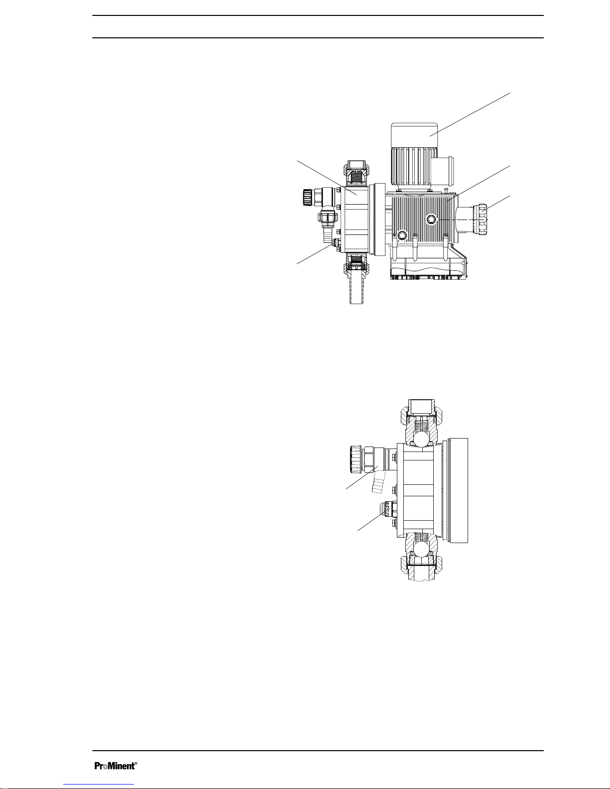
4 Overview of equipment and control elements
1
2
3
4
5
P_SI_0070_SW
Fig. 3: Overview of equipment and control elements S3Ba
1 Drive motor
2 Drive unit
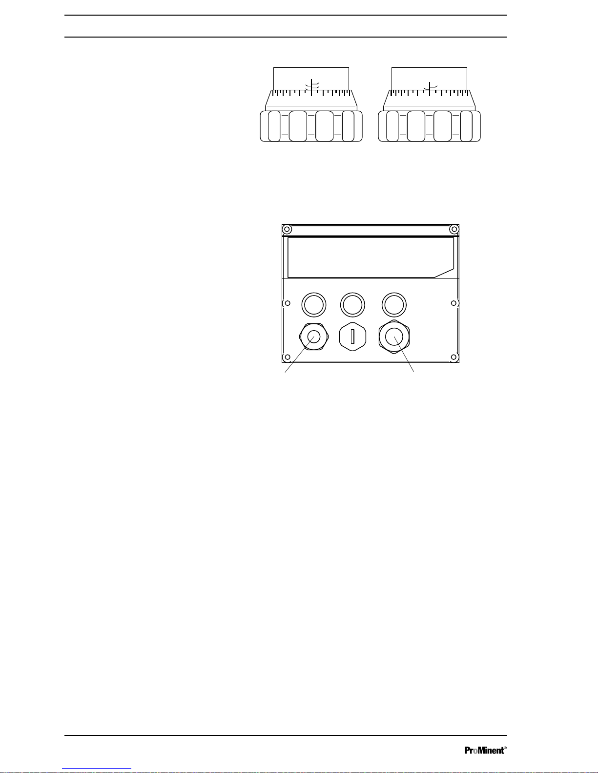
3 Stroke length adjustment knob
4 Liquid end with relief valve
5 Diaphragm rupture sensor
1
2
P_SI_0088_SW
Fig. 4: Sigma control elements
1 Relief valve
2 Diaphragm rupture sensor (visual)
Overview of equipment and control elements
27
Page 28
20 0
0
50
25
75
5
75%
0
5
0
25
10
30%
P_SI_0095_SW
Fig. 5: Adjusting the stroke length
n 100 % = 4 rotations
n 25 % = 1 rotation
n 0.5 % = 1 scale mark on stroke adjustment dial
PG11
PG9
1
2
3
A B
P_SI_0036
Fig. 6: Front cover for version with pacing relay
A Pacing relay cable
B Supply voltage cable for pacing relay PCB
Overview of equipment and control elements
28
Page 29
5 Functional description
5.1
Pump
The metering pump is an oscillating diaphragm pump, the stroke length of
which is adjustable. An electric motor drives the pump.
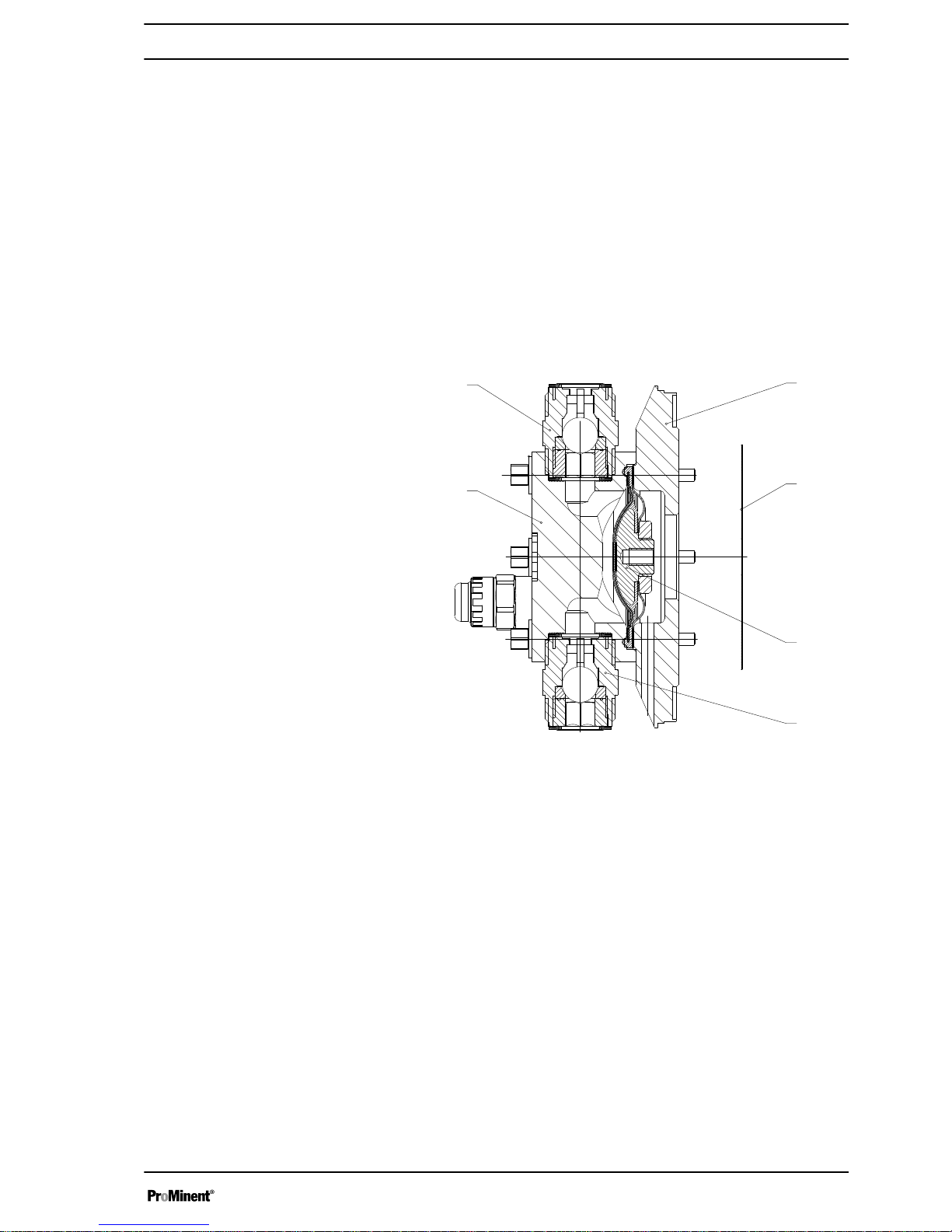
5.2 Liquid end
The diaphragm (2) hermetically shuts off the pump volume of the dosing
head (4) towards the outside. The suction valve (1) closes as soon as the
diaphragm (2) is moved in to the dosing head (4) and the feed chemical
flows through the discharge valve (3) out of the dosing head. The dis‐
charge valve (3) closes as soon as the diaphragm (2) is moved in the
opposite direction due to the vacuum pressure in the dosing head and
fresh feed chemical flows through the suction valve (1) into the dosing
head. One cycle is thus completed.
4
2
1
5
3
13
Fig. 7: Cross-section through the liquid end
1 Suction valve
2 Diaphragm
3 Discharge valve
4 Dosing head
5 Backplate
13 Safety diaphragm
5.3 Integral relief valve
The integral relief valve normally operates as a simple, directly controlled
bleeder valve. The feed chemical then flows out through the hose connec‐
tion, e.g. into a storage tank, as soon as the pressure exceeds the pre-set
pressure value.
The integral relief valve can only protect the motor and the gear, and then
only against impermissible positive pressure that is caused by the
metering pump itself. It cannot protect the system against positive pres‐
sure.
The integral relief valve works as a bleed valve if the rotary dial is turned
clockwise up to the "open" stop, acting as a priming aid when starting up
the pump against pressure.
Functional description
29
Page 30
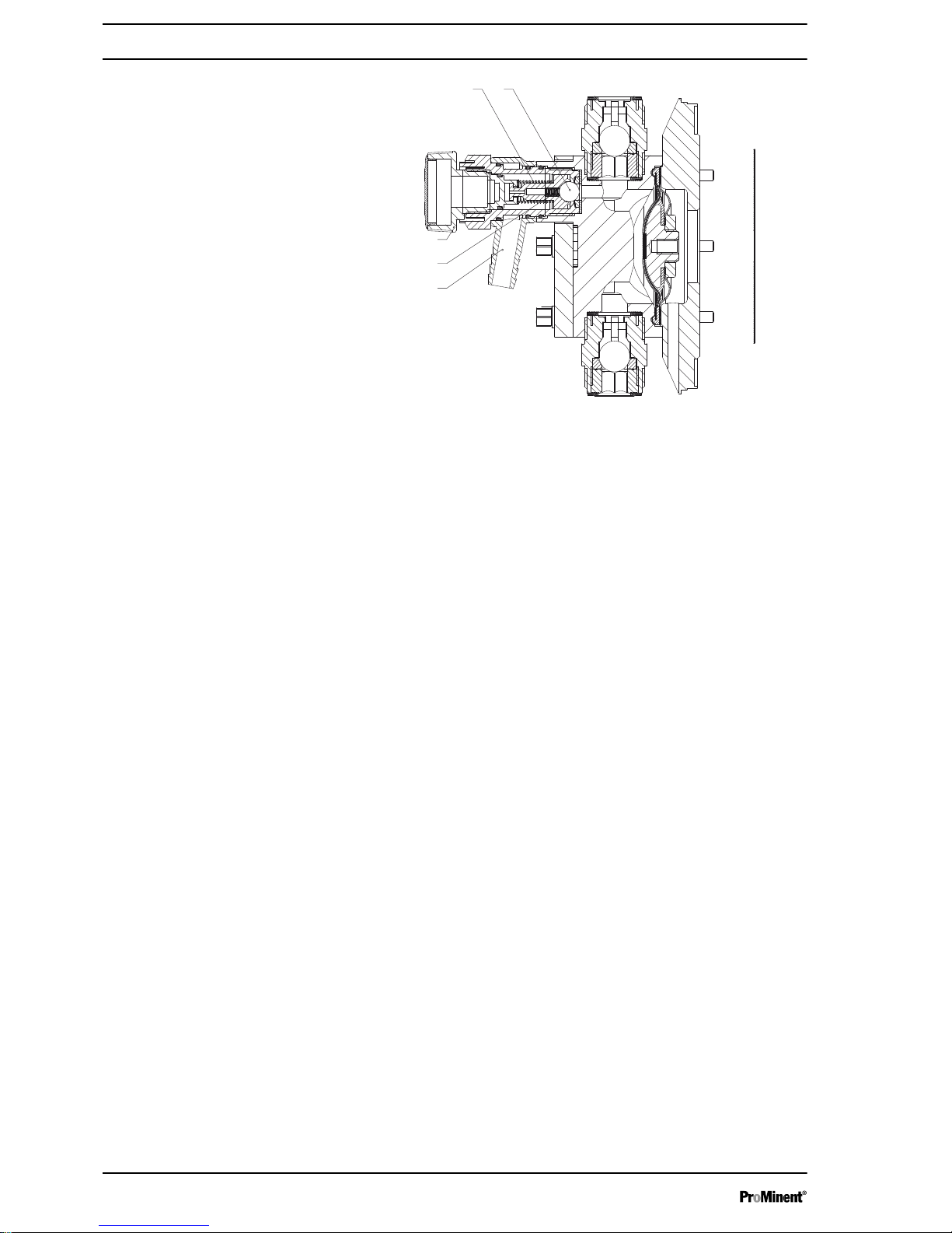
1 2
5
4
3
P_SI_0019
Fig. 8: Integral relief valve
1 Spring, large
2 Ball
3 Rotary dial
4 Spring, small
5 Hose connection
5.4 Multi-layer safety diaphragm
With visual diaphragm rupture sensors, in the event of a diaphragm rup‐
ture, the lowered red cylinder (6) springs forward beneath the transparent
cover (7) so that it then becomes clearly visible - see
Fig. 9.
With the electrical diaphragm rupture sensor, a switch is switched. A sig‐
nalling device must be connected to signal the diaphragm rupture.
Fig. 9: Visual diaphragm rupture sensor, triggered and untriggered
Functional description
30
Page 31

6 Assembly
Compare the dimensions on the dimension sheet with
those of the pump.
1. Select a suitable motor - it must correspond to the data for one of
the motors from the "Motor data" table - see Chapter "Technical
data".
2. Fit the motor correctly on the flange - qualified personnel!
Observe the coupling operating instructions!
With a claw coupling: The claw on the motor shaft must be fixed at
the correct height, see Fig. 10
3. Secure set screws and threaded connections to prevent them from
loosening.
WARNING!
EX is relevant in areas at risk from explosion!
4. As you have converted an "incomplete machine" into a complete
machine, you must perform a conformity assessment, risk assess‐
ment, create an EC Declaration of Conformity, fit a company name‐
plate, ... . With ATEX pumps: additionally perform an ignition hazard
assessment.
5. Complete the pump documentation / operating instructions.
QQ
P_HY_0060_SW
Fig. 10: Correct height of the clutch claw on the motor shaft
Install the motor - with designs without
motor
Assembly
31
Page 32

Tab. 3: Sigma
Size Motor flange Q
71 B 14/105 29
- 56C/138 1.14”
71 B 14/105 29
80 B 14/105 52.5
63 B 5/140 * (26)
Dimensions in mm - unless otherwise indicated.
* Motor is fitted directly onto the motor flange without intermediate flange
and claw coupling.
WARNING!
The pump can break through the base or slide off it
– Ensure that the base is horizontal, flat and perma‐
nently load-bearing.
Capacity too low
Vibrations can disturb the liquid end valves.
–
Do not allow the base to vibrate.
WARNING!
Motor may overheat
If the necessary cooling air supply is not guaranteed, the
motor may overheat. In an area at risk from explosion, it
could trigger an explosion.
– Maintain sufficient clearance between the air intake
opening and the walls. The distance should be
greater than 1/4 of the diameter of the air intake
opening.
–
The fan must not suck in the exhaust air from other
devices.
CAUTION!
Danger from incorrectly operated or inadequately main‐
tained pumps
Danger can arise from a poorly accessible pump due to
incorrect operation and poor maintenance.
– Ensure that the pump is accessible at all times.
–
Adhere to the maintenance intervals.
Position the pump so that control elements, such as the stroke length
adjustment knob or the indicating dial A, are easily accessible.
Base
h
P_MOZ_0016_SW
Fig. 11
Space requirement
A
A
P_MOZ_0018_SW
Fig. 12
Assembly
32
Page 33

1 Discharge valve
2 Dosing head
3 Suction valve
Ensure there is sufficient free space (f) around the dosing head as well as
the suction and discharge valve so that maintenance and repair work can
be carried out on these components.
Capacity too low
The liquid end valves cannot close correctly if they are
not upright.
–
Ensure that the discharge valve is upright.
Capacity too low
Vibrations can disturb the liquid end valves.
–
Secure the metering pump so that no vibrations can
occur.
Take the dimensions (m) for the fastening holes from the appropriate
dimensional or data sheets.
Use appropriate screws to fix the pump base to the supporting floor.
Using 4 sufficiently strong screws, screw the pump to the support
surface through the 4 holes in the frame.
1
3
2
f
f
f
P_MOZ_0017_SW
Fig. 13
Liquid end alignment
Fastening
DNm
m
P_MOZ_0015_SW
Fig. 14
Instructions
Assembly
33
Page 34

7 Installation, hydraulic
CAUTION!
Danger of injury to personnel and material damage
Disregarding the technical data during installation can
lead to personal injuries or damage to property.
– Observe the technical data - refer to the "Technical
data" chapter and, where applicable, the operating
instructions for the accessories.
WARNING!
ATEX pumps in areas at risk from explosion
– Metering pumps must have an appropriate safety
relief valve on the discharge side (to protect against
excessive heating due to overloading or impact
sparks caused by the breakage of power end parts).
WARNING!
Risk of fire with flammable feed chemicals
– Flammable media may only be pumped using
metering heads made of stainless steel, Hastelloy C,
PRFE with carbon or PP with carbon.
–
Metering pumps can be used for metering flam‐
mable media, but fundamentally only those
designed with an ATEX diaphragm rupture sensor
and a discharge-side flow control, which both stop
the pump as soon as a diaphragm rupture or no flow
is detected.
– Do not allow it to run dry. Take appropriate protec‐
tive measures.
– If necessary, the operator must implement further
measures.
WARNING!
Warning of feed chemical reactions to water
Feed chemicals that should not come into contact with
water may react to residual water in the liquid end that
may originate from works testing.
– Blow the liquid end dry with compressed air through
the suction connector.
–
Then flush the liquid end with a suitable medium
through the suction connector.
WARNING!
The following measures are an advantage when working
with highly aggressive or hazardous feed chemicals:
– Install a bleed valve with recirculation in the storage
tank.
–
Install an additional shut-off valve on the discharge
or suction ends.
Installation, hydraulic
34
Page 35

CAUTION!
Warning of feed chemical spraying around
PTFE seals, which have already been used / com‐
pressed, can no longer reliably seal a hydraulic connec‐
tion.
– New, unused PTFE seals must always be used.
CAUTION!
Suction problems are possible
The valves may no longer close properly with feed
chemicals with a particle size of greater than 0.3 mm.
– Install a suitable filter in the suction line.
CAUTION!
Warning of the discharge line rupturing
With a closed discharge line (e.g. due to a clogged dis‐
charge line or by closing a valve), the pressure that the
metering pump generates can reach several times the
permissible pressure of the system or the metering
pump. This could lead to lines bursting resulting in dan‐
gerous consequences with aggressive or toxic feed
chemicals.
– Install a relief valve that limits the pressure of the
pump to the maximum permissible operating pres‐
sure of the system.
CAUTION!
Uncontrolled flow of feed chemical
Feed chemical may press through a stopped metering
pump if there is back pressure.
– Use an injection valve or a vacuum breaker.
CAUTION!
Uncontrolled flow of feed chemical
Feed chemical may press through the metering pump in
an uncontrolled manner in the event of excessive pri‐
ming pressure on the suction side of the metering pump.
– Do not exceed the maximum permissible priming
pressure for the metering pump or
–
set up the installation properly.
Installation, hydraulic
35
Page 36

CAUTION!
Warning of leaks
Leaks can occur on the pump connection depending on
the insert used.
– The pump is supplied with PTFE moulded compo‐
site seals with a flare, which are used for the pump
connectors, which seal the connectors between
grooved pump valves and ProMinent grooved
inserts - see Fig. 15.
–
Use an elastomer flat seal in the event that an
unflared insert is used (e.g. third party part) - see
Fig. 16.
CAUTION!
Warning of backflow
Liquid ends, foot valves, back pressure valves, relief
valves or spring-loaded injection valves do not constitute
absolutely leak-tight sealing elements.
– Use a shut-off valve, a solenoid valve or a vacuum
breaker for this purpose.
WARNING!
Product can be dangerously contaminated
Only with the design "Physiologically safety with regard
to wetted materials".
If the integral bleed valve or the integral relief valve
opens, the feed chemical comes into contact with phys‐
iologically harmful seals.
– Do not route feed chemical that escapes from the
integral bleed valve or the integral relief valve back
into the process.
CAUTION!
Danger due to incorrect use of the integral relief valve
The integral relief valve can only protect the motor and
the gear, and then only against impermissible positive
pressure that is caused by the metering pump itself. It
cannot protect the system against positive pressure.
– Protect the motor and gear of the system against
positive pressure using other mechanisms.
–
Protect the system against illegal positive pressure
using other mechanisms.
CAUTION!
Warning of feed chemical spraying around
If no relief valve was connected to the overflow line, the
feed chemical sprays out of the hose connection as soon
as the relief valve opens.
– An overflow line must always be connected to the
integral relief valve and be fed back to the storage
tank or - if required by the regulations - into a special
storage tank.
P_SI_0021
Fig. 15: Moulded composite seals with
corrugated insert
P_SI_0022
Fig. 16: Elastomer flat seal for a smooth
insert
Integral relief valve
Installation, hydraulic
36
Page 37

CAUTION!
Danger of cracking
Cracking of the PVT liquid end can occur if a metal over‐
flow line is connected to the relief valve.
– Never connect a metal overflow line to the relief
valve.
CAUTION!
Danger of the integral relief valve failing
The integral relief valve no longer operates reliably with
feed chemicals having a viscosity of greater than 200
mPa s.
– Only use the integral relief valve with feed chemicals
having a viscosity up to 200 mPa s.
CAUTION!
Warning against leaks
Feed chemical which remains in the overflow line at the
relief valve, can attack the valve or cause it to leak
– Route the overflow line with a continuous slope and
moreover with the tube nozzle pointed downwards see Fig. 17.
If the overflow line is fed into the suction line, the bleed
function is blocked.
Therefore lead the overflow line back into the storage
tank.
When operating the integral relief valve close to the
opening pressure, a minimal overflow into the overflow
line can occur.
CAUTION!
Danger resulting from unnoticed diaphragm rupture
If the pump has been ordered with an electric diaphragm
rupture sensor, it still has to be installed.
– Screw the enclosed diaphragm rupture sensor into
the liquid end.
CAUTION!
Warning of unnoticed diaphragm rupture
Only above approximately 2 bar system back pressure is
a signal generated in the event of the rupture of a dia‐
phragm.
– Only rely on the diaphragm rupture sensor with back
pressures of greater than 2 bar.
Or install a back pressure valve and set it to a min‐
imum of 2 bar – if the installation permits this.
P_SI_0023
Fig. 17: Permissible alignment of the relief
valve
Diaphragm rupture sensor
Installation, hydraulic
37
Page 38

7.1 Basic installation notes
CAUTION!
Danger from rupturing hydraulic components
Hydraulic components can rupture if the maximum per‐
missible operating pressure is exceeded.
– Never allow the metering pump to run against a
closed shut-off device.
–
With metering pumps without integral relief valve:
Install a relief valve in the discharge line.
CAUTION!
Hazardous feed chemicals can escape
With hazardous feed chemicals: Hazardous feed chem‐
ical can leak out when using conventional bleeding pro‐
cedures with metering pumps.
– Install a bleed line with return line into the storage
tank.
Shorten the return line so that it is not immersed in the feed chem‐
ical in the storage tank.
P_MOZ_0043_SW
2
1
A)
B)
*
PD
1
2
Fig. 18: (A) standard installation, (B) with pulsation damper
1 Main line
2 Storage tank
Symbol Explanation Symbol Explanation
Metering pump Foot valve with filter mesh
Injection valve Level switch
Back pressure valve or safety valve Manometer
Safety information
Legend for hydraulic diagram
Installation, hydraulic
38
Page 39

8 Installation, electrical
CAUTION!
Danger of injury to personnel and material damage
Disregarding the technical data during installation can
lead to personal injuries or damage to property.
– Observe the technical data - refer to the "Technical
Data" chapter and, where applicable, the operating
instructions for the accessories.
WARNING!
ATEX pumps in areas at risk from explosion
– Electrically connect the electrical units listed on the
earthing diagram, cleanly and permanently, to an
electrically clean earthing point, - e.g. with an
earthing bar on your system.
– Electrically connect the electrical units fitted with a
potential equalisation cable to each other, cleanly
and permanently, to an electrically clean potential
equalisation point - e.g. with a potential equalisation
bar on your system.
– Note the enclosed documentation for the individual
electrical components.
WARNING!
Danger of fire with flammable feed chemicals
– The ATEX diaphragm rupture sensor and a dis‐
charge-side flow control must both stop the pump as
soon as a diaphragm rupture or no flow is detected.
WARNING!
Danger of electric shock
Unprofessional installation may lead to electric shocks.
– Crimp cable end sleeves onto all shortened cable
cores.
–
Only technically trained personnel are authorised to
undertake the electrical installation of the device.
WARNING!
Danger of electric shock
In the event of an electrical accident, it must be possible
to quickly disconnect the pump, and any electrical ancil‐
laries which may possibly be present, from the mains.
– Install an emergency cut-off switch in the mains
supply line to the pump and any electrical ancillaries
which may be present or
–
Integrate the pump and electrical ancillaries which
may be present in the emergency cut-off manage‐
ment of the system and inform personnel of the iso‐
lating option.
Installation, electrical
39
Page 40

WARNING!
Danger of electric shock
This pump is equipped with a protective earth conductor,
to reduce the risk arising from an electric shock.
– Connect the PE conductor to "earth" with a clean
and permanent electrical connection.
WARNING!
Danger of electric shock
A mains voltage may exist inside the motor or electrical
ancillaries.
– If the housing of the motor or electrical ancillaries
has been damaged, you must disconnect it from the
mains immediately. The pump must only be returned
to service after an authorised repair.
WARNING!
Danger of electric shock
There can still be dangerous voltage present for 3
minutes in the interior of motor designs with integral fre‐
quency converter.
– Only open the drain screw 3 minutes after the mains
voltage has been switched off.
WARNING!
Never change the “Motor voltage” and “Cycle frequency”
parameters with motor designs with integral frequency
converter.
The parameters on delivery from ProMinent do not cor‐
respond to the motor manufacturer’s factory settings.
If other parameters are to be changed, then we recom‐
mend speaking to ProMinent head office in Heidelberg.
What requires electrical installation?:
n Motor
n External fan (optional)
n Stroke control drive (optional)
n Stroke adjusting drive (optional)
n Diaphragm rupture sensor (optional)
n Stroke sensor (optional)
n Pacing relay (option)
n Frequency converter (optional)
n Earthing wires (to be provided on site)
n Potential equalisation line (to be provided on site, prescribed in the
area at risk from explosion)
Installation, electrical
40
Page 41

WARNING!
ATEX pumps in areas at risk from explosion
– Use a suitable motor protection switch to protect
power end motors. Use motor protection approved
for this application with Ex"e" motors. (Protection
against warming caused by overloading)
–
Ensure that motors are only installed and checked in
areas at risk from explosion by a "recognised com‐
petent" person.
– Observe the enclosed operating instructions for the
Ex motor.
WARNING!
Only motors with a frequency converter: Danger of elec‐
tric shock
The danger of electric shock remains for 3 minutes after
the mains voltage has been switched off on conducting
parts of the motor with an integrated frequency converter
and on the lines themselves.
– After switching off, allow the device to stand for 3
minutes before opening the terminal box.
CAUTION!
The motor can be damaged
Provide appropriate motor protection devices (e.g. motor
protection switch with thermal overcurrent trip) to protect
the motor from overloading.
Fuses do not provide motor protection.
CAUTION!
Operation of the system can be disrupted
If a motor protection switch is used, operation of the
system can be disrupted by an inappropriate setting.
– Set the response threshold of the motor protection
switch to approx. 1.4 ... 1.5 times the nominal cur‐
rent of the motor (motor nameplate) (due to pulsing
load).
This does not lead to the motor being overloaded.
CAUTION!
Only motors with a frequency converter: The motor can
be damaged
The input current limiter could be damaged if a motor
with an integrated frequency converter is restarted within
3 minutes of the mains voltage being switched off.
– After switching off, allow the device to stand for at
least 3 minutes before restarting.
– If the motor is controlled via a control, take this into
consideration at the control.
Motor
P_SI_0012_SW
Fig. 19: Direction of rotation of motor
Installation, electrical
41
Page 42

CAUTION!
Pump can be damaged
The pump can be damaged if the motor drives the pump
in the wrong direction.
– When connecting the motor, pay attention to the cor‐
rect direction of rotation indicated by the arrow on
the fan cover, as shown in Fig. 19.
Use an electrical isolating device in the mains supply
cable, such as a mains switch, to switch off the pump
independently of the entire installation (e.g. for repairs).
1. Install a motor protection switch, as the motors have no fuse.
2. Install an emergency cut-off switch or include the motor in the sys‐
tem's emergency cut-off management scheme.
3. Only connect the motor to the power supply using a suitable cable.
–
Key motor data can be found on the nameplate and
in the "Technical data” chapter.
–
The terminal wiring diagram is located in the ter‐
minal box.
Motor data sheets, special motors, special motor
flanges, external fan, temperature monitoring
–
For further information on the motor with identity
code specification "S", refer to our website
www.prominent.com. Motor data sheets can be
requested for all other motors.
–
With motors other than those with identity code
specifications "S", "M" or "N": Pay special attention
to the operating instructions for the motors.
–
Special motors or special motor flanges are avail‐
able on request.
CAUTION!
Provide a separate power supply for the external fan for
motors with external fans (identity code specification "R"
or "Z").
Connect the motor as per the wiring diagram for the controller, if it is con‐
trolled by an electronic control unit (such as direct current motors by a fre‐
quency converter).
Connect the motors in accordance with the enclosed wiring diagram or as
per the wiring diagram fixed to the inside of the housing.
External fan
Variable speed motors with frequency
converter
Stroke length actuators / control power
ends
Installation, electrical
42
Page 43

CAUTION!
Only operate stroke length actuators / control drives
when the pump is running.
Otherwise they will become damaged.
WARNING!
Danger of electric shock
In the event of a defect, there is a danger of electric
shock if conductive feed chemicals are present.
– For safety reasons, we recommend connecting to
protective low voltage, e.g. in accordance with EN
60335-1 (SELV).
CAUTION!
Danger resulting from unnoticed diaphragm rupture
If the pump has been ordered with an electric diaphragm
rupture sensor, it must also be electrically installed.
– Electrically wire the enclosed diaphragm rupture
sensor to a suitable monitoring device.
a) Diaphragm rupture sensor with switch contact
–
The cable can be connected as required.
b) Namur sensor, inherently safe
Make sure that the monitoring/feed equipment installed by the customer is
capable of evaluating the current variations of the Namur sensor to indi‐
cate a diaphragm rupture!
WARNING!
The following applies in areas at risk from explosion:
– Note the details of the type examination certificate
PTB 00 ATEX 2048 X for the Namur sensor
NJ1.5-8GM-N as well.
Connect the stroke sensor to a suitable monitoring device according
to the technical data provided with the monitoring device and that of
the stroke sensor - see chapter "Technical data".
Make sure that the monitoring/feed equipment installed by the cus‐
tomer is capable of evaluating the current variations of the Namur
sensor to indicate a stroke.
Diaphragm rupture sensor (optional)
Stroke sensor (identity code specification
"Stroke sensor": 3)
Installation, electrical
43
Page 44

WARNING!
The following applies in areas at risk from explosion:
– Note the details of the type examination certificate
PTB 00 ATEX 2048 X for the Namur sensor
NJ1.5-8GM-N as well.
1. Install the cable which originates from the pacing relay - see the
figure in the chapter entitled "Overview of equipment and control
elements": Cable A, left.
The cable polarity is unimportant.
2. Install the power supply cable to the pacing relay PCB - see the
figure in the chapter entitled "Overview of equipment and control
elements": Cable B, right.
CAUTION!
Warning of overload
If the current through the relay becomes too high,
it can be destroyed by heating.
– Fit a circuit breaker.
Pacing relay terminal output data
Data Value Unit
Maximum voltage 24 VDC
Maximum current 100 mA
Closing duration, approx. 100 ms
Service life *
50 x 106 (10 V,
10 mA)
Play
* at rated load
The contacts are potential-free.
The pacing relay is N/O as standard.
Tab. 4: Supply voltage for pacing relay PCB
Available supply vol‐
tages
Mains frequency Power consumption
230 V AC (180-254 V) 50 / 60 Hz 10 mA (at 230 V, 50 Hz)
115 V AC (90-134 V) 50 / 60 Hz 15 mA (at 115 V, 60 Hz)
24 V DC (20-28 V) - 10 mA (at 24 V DC)
Install the heating cartridge in line with its documentation. It must
only be connected to the power unit supplied!
Pacing relay (identity code specification
"Stroke sensor": 2)
Heating cartridge
Installation, electrical
44
Page 45

Connect the electrical components of the entire installation supplied
cleanly and permanently to an electrically clean earthing point, e.g. with an
earthing bar on site - see earthing diagrams in the appendix.
The entire installation supplied is provided ex works with the necessary
potential equalisation lines. Electrically connect an additional potential
equalisation cable from the potential equalisation cables from this system
cleanly and permanently to an electrically clean potential equalisation
point, e.g. to a potential equalisation bar on site.
Install the other units in line with their documentation.
Earthing lines
Potential equalisation line (prescribed in
the area at risk from explosion)
Other units
Installation, electrical
45
Page 46

9 Start up
WARNING!
ATEX pumps in areas at risk from explosion
– Make sure that a suitably competent person checks
whether the appropriate installation information from
the "Installation " chapter has been implemented
correctly.
–
Make sure that a "recognised competent person"
checks the electrical installation and in particular the
intrinsically safe power circuits.
– Set the opening pressure of the relief valve to a
maximum of no more than 1.5 times the nominal
pressure of the pump.
WARNING!
ATEX pumps in areas at risk from explosion
The ignition temperature is reduced significantly below
the ignition temperature at atmospheric pressure due to
compression with the discharge stroke of the possibly
ignitable vapour-air mixture.
– Do not allow it to run dry.
WARNING!
Only motors with a frequency converter: Danger of elec‐
tric shock
The danger of electric shock remains for 3 minutes after
the mains voltage has been switched off on conducting
parts of the motor with an integrated frequency converter
and on the lines themselves.
– After switching off, allow the device to stand for 3
minutes before opening the terminal box.
CAUTION!
Warning of personal injury and material damage
The metering pump may only be operated by trained
personnel. The operator is responsible for ensuring that
under the given operating conditions (pressure, tempera‐
ture, corrosiveness, etc.) danger to the operating per‐
sonnel is avoided by use of appropriate accident preven‐
tion measures.
CAUTION!
Only motors with a frequency converter: The motor can
be damaged
The input current limiter could be damaged if a motor
with an integrated frequency converter is restarted within
3 minutes of the mains voltage being switched off.
– After switching off, allow the device to stand for at
least 3 minutes before restarting.
Safety information
Start up
46
Page 47

CAUTION!
Feed chemical could escape
– Check suction and discharge lines, and liquid end
with valves, for leak-tightness and tighten if neces‐
sary.
–
Check whether the necessary flushing pipes or
bleed lines have been connected.
CAUTION!
Liquid end may be damaged
– Always fit a filter in the suction line with feed chemi‐
cals with a particle size greater than 0.3 mm
CAUTION!
Prior to commissioning, check that the power end motor
and corresponding ancillary equipment is connected in
compliance with the regulations!
CAUTION!
Adhere to the instructions in the frequency converter
operating instructions when using pumps with speed
control
CAUTION!
Danger of material damage
Observe the details in the chapter "Technical data"
(pressure, viscosity, resistance, etc.).
Check that the installation complies with the regulations
CAUTION!
Danger resulting from unnoticed diaphragm rupture
If the pump has been ordered with an electric diaphragm
rupture sensor, it still has to be installed.
– Screw the enclosed diaphragm rupture sensor into
the liquid end.
CAUTION!
Warning of unnoticed diaphragm rupture
Only above approximately 2 bar system back pressure is
a signal generated in the event of the rupture of a dia‐
phragm.
– Only rely on the diaphragm rupture sensor with back
pressures of greater than 2 bar.
Or install a back pressure valve and set it to a min‐
imum of 2 bar – if the installation permits this.
Observe the technical data
Checking for regulation-compliant installa‐
tion
Diaphragm rupture sensor
Start up
47
Page 48

CAUTION!
Possible environmental and material damage
In event the red gear bleeding plug is sealed, during
operation it prevents any pressure compensation
between the drive housing and the surroundings. This
ensure that oil can be pushed from the drive housing.
– Remove the gear bleeding plug before commis‐
sioning.
Before start up, remove the red gearbox vent stopper, see "Overview of
equipment and control elements” chapter.
When the pump is idle, check whether the oil level in the pump is in the
middle of the oil level indicator.
This will rule out the pump losing oil and suffering damage.
The valves may no longer close properly with feed
chemicals with a particle size of greater than 0.3 mm.
–
Install a suitable filter in the suction line.
When commissioning the unit, check whether the drive motor is rotating
correctly - check this against the arrow on the motor housing or the dia‐
gram in the chapter entitled "Electrical Installation."
WARNING!
Risk of injury from the fan impeller
The fan impeller beneath motor's fan cowling can cause
severe injuries while it is turning.
– The pump must only be connected to the mains
voltage with the fan cowling closed.
CAUTION!
Danger due to incorrect use of the integral relief valve
The integral relief valve can only protect the motor and
the gear, and then only against impermissible positive
pressure that is caused by the metering pump itself. It
cannot protect the system against positive pressure.
– Protect the motor and gear of the system against
positive pressure using other mechanisms.
–
Protect the system against illegal positive pressure
using other mechanisms.
Remove the gearbox vent stopper
Checking the oil level
Avoid particles
Checking the direction of rotation
Using the integral relief valve
Start up
48
Page 49

CAUTION!
Danger of the integral relief valve failing
The integral relief valve no longer operates reliably with
feed chemicals having a viscosity of greater than 200
mPa s.
– Only use the integral relief valve with feed chemicals
having a viscosity up to 200 mPa s.
1. Hydraulically isolate the discharge line from the pump using an iso‐
lation device.
2. Turn the rotary dial on the integral relief valve in a counter-clockwise
direction as far as the "open" stop.
ð
The excess pressure escapes through the hose connector.
3. Run the pump until the feed chemical coming out of the hose con‐
nector is free from bubbles.
4. Turn the rotary dial on the integral relief valve in a clockwise direc‐
tion up to the "close" stop.
ð
The pump can be started.
When operating the integral relief valve close to the
opening pressure, a minimal overflow into the overflow
line can occur.
Only adjust the stroke length when the pump is running.
This is easier and also better for the pump.
20 0
0
50
25
75
5
75%
0
5
0
25
10
30%
P_SI_0095_SW
Fig. 20: Adjusting the stroke length
n 100% = 4 rotations
n 25 % = 1 rotation
n 0.5 % = 1 scale mark on stroke adjustment dial
Check whether the earthing lines in the pump's electrical units are cor‐
rectly connected and connected to a clean earth wire - see earthing dia‐
grams in the appendix.
Check whether the potential equalisation lines are sitting correctly on the
pump and connected to a clean potential equalisation point.
Check for the correct function of the auxiliary equipment and for correct
interplay.
Priming against pressure
Adjusting the stroke length
Earthing lines
Potential equalisation lines (mandatory
with ATEX)
Auxiliary equipment
Start up
49
Page 50

10 During operation
WARNING!
Fire hazard with flammable media
Only with flammable media: They can be ignited by
oxygen.
– The pump may not work if there is a mixture of feed
chemical with oxygen in the liquid end. A specialist
may need to take appropriate actions (using inert
gas, ...).
WARNING!
Personnel injury and material damage may occur
During use all units, protective equipment, additional
devices must be fitted, operational and tightly closed.
WARNING!
Sparking caused by dry running
If the bearings in the power end run dry, sparks can be
formed.
– Check for oil leaks.
–
When the pump is idle, the pump oil level must
slightly cover the lower oil inspection window.
Observe the instructions in the "Start up" chapter and
the operating instructions for the other machine compo‐
nents.
During operation
50
Page 51

11 Maintenance
WARNING!
ATEX pumps in areas at risk from explosion
– Carry out a general check to ensure that the system
is working properly, particularly the power end and
bearings, by regularly monitoring it (for leaks,
noises, temperatures, smell, etc.).
–
Do not allow the pump to run hot due to a lack of oil.
With lubricated metering pumps, regularly check for
the presence of lubricant, for example by checking
the liquid level, visual leak control etc. If oil is
leaking, examine the leakage point immediately and
eliminate the cause.
– Check the correct operation of the relief valve down‐
stream of the pump. In premises at risk from explo‐
sion, the relief valve should prevent the gear from
becoming overloaded and becoming hot.
– Observe the enclosed operating instructions for the
Ex motor.
– Check / replace worn gear ring etc. of the clutch.
– When cleaning plastic components, ensure that no
electrostatic charge is generated by the use of too
dry a cloth.
– Prevent serious deposits of dust on the motor.
– Consider potential equalisation before you approach
any pump equipment that could be at a different
electrical potential (such as pipes or tools).
– Only with stroke control motor: Wait 3 minutes after
switching off before opening the housing.
– Replace wear parts, such as bearings, when there is
an identifiable incidence of unacceptable wear.
– After 40,000 h: The upper screw shaft bearing must
be replaced for ongoing ATEX use.
– Appropriate diagnostic equipment for bearing
damage is recommended for the premature detec‐
tion of bearing damage.
– Check whether the potential equalisation lines are
all sitting correctly with clean contacts. Use the equi‐
potential bonding drawings as an aid – see
Appendix.
– Check whether the earth lines are all sitting correctly
with clean contacts. Use the equipotential bonding
drawings as an aid – see Appendix.
– Only use genuine spare parts as replacements.
WARNING!
ATEX pumps in areas at risk from explosion
Static electricity can cause ignition sparks
– Always earth the discharge line and suction line first
before working on the pump.
WARNING!
Fire hazard with flammable media
Only with flammable media: They can be ignited by
oxygen.
– The pump may not work if there is a mixture of feed
chemical with oxygen in the liquid end. A specialist
may need to take appropriate actions (using inert
gas, ...).
Safety information
Maintenance
51
Page 52

WARNING!
It is mandatory that you read the safety information and
specifications in the "Storage, Transport and Unpacking"
chapter prior to shipping the pump.
WARNING!
Risk of injury from the fan impeller
The fan impeller beneath motor's fan cowling can cause
severe injuries while it is turning.
– The pump must only be connected to the mains
voltage with the fan cowling closed.
CAUTION!
Warning of feed chemical spraying around
Feed chemical can spray out of the hydraulic compo‐
nents if they are manipulated or opened due to pressure
in the liquid end and adjacent parts of the system.
– Disconnect the pump from the mains power supply
and ensure that it cannot be switched on again by
unauthorised persons.
–
Depressurise the system before commencing any
work on hydraulic parts.
WARNING!
Warning of hazardous feed chemical
Should a dangerous feed chemical be used: it may
escape from the hydraulic components when working on
the pump, material failure or incorrect handling of the
pump.
– Take appropriate protective measures before
working on the pump (e.g. safety glasses, safety
gloves, ...). Adhere to the material safety data sheet
for the feed chemical.
–
Drain and flush the liquid end before working on the
pump.
WARNING!
Danger of an electric shock
When working on the motor or electrical auxiliary equip‐
ment, there is a danger of an electric shock.
– Before working on the motor, take note of the safety
instructions in its operating instructions!
– Should external fans, servomotors or other auxiliary
equipment be installed, these should also be discon‐
nected and checked that they are voltage free.
Check the pump installation for:
n Leaks
n Abnormal noises or squeaks
n Abnormal temperatures
n Abnormal odours
n Abnormal vibrations
n Other anomalies
Inspection, daily
Maintenance
52
Page 53

WARNING!
In the area at risk from explosion: stop the pump imme‐
diately and rectify these anomalies. ProMinent Service
may be needed if required.
Under heavy loading (e.g. continuous operation) shorter
maintenance intervals are recommended than those
given.
Third-party spare parts for the pumps may result in prob‐
lems when pumping.
–
Only use original spare parts.
–
Use the correct spare parts kits. In the event of
doubt, refer to the exploded views and ordering
information in the appendix.
Interval Maintenance work Personnel
Quarterly*
n Check that the metering lines are tight at the liquid end and
check for leak-tightness.
n Check that the suction valve and discharge valve are firmly fixed
in place and tightly sealed.
n Check the leak-tightness of the entire liquid end - particularly
around the leakage hole!
With critical applications, check or replace the diaphragm at reg‐
ular intervals - see
Ä ‘Check the condition of the metering dia‐
phragm’ on page 54
.
n Check that the dosing head screws are tight.
n Check that the diaphragm rupture sensor is firmly seated.
n Check whether the diaphragm rupture sensor stops the pump or
generates an alarm after it has been triggered.
n Check that the flow is correct: Allow the pump to prime briefly.
Observe the maximum permissible operating pressure!
n Check the oil level.
n Check that the electrical connectors are intact.
n Check the tight, clean electrical connection of the earthing wires.
n Check the tight, clean electrical connection of the potential
equalisation wires.
Technical per‐
sonnel
After approx. 4,000 oper‐
ating hours
Check the gear ring/DZ element of the coupling as per their oper‐
ating instructions.
Technical per‐
sonnel
After approx. 5000 oper‐
ating hours
Change gear oil - refer to "Changing gear oil" in this chapter. Instructed per‐
sonnel
After 18,000 operating
hours or 23,500 operating
hours (API)
Adhere to the motor manufacturer's recommendations - see oper‐
ating instructions for the motor.
After 40,000 h: The upper screw shaft bearing must be replaced for
ongoing ATEX use.
* Under normal loading (approx. 30% of continuous operation).
Under heavy loading (e.g. continuous operation, aggressive feed chemi‐
cals etc.): shorter intervals.
Standard liquid ends:
Maintenance
53
Page 54

The diaphragm is a wearing part, the service life of which is dependent on
the following parameters:
n System back pressure
n Operating temperature
n Feed chemical properties
When using abrasive feed chemicals, the diaphragm service life is
reduced. In these cases, more frequent checking of the diaphragm is rec‐
ommended.
Data Value Unit
Tightening torques for dosing head
screws:
12 ... 12.0 Nm
WARNING!
Warning of eye injuries
When opening the relief valve, a spring under high ten‐
sion can jump out.
– Wear protective glasses.
Draining gear oil
1
3
2
P_SI_0143_SW
Fig. 21
1. Remove the vent screw (1).
2. Place an oil trough under the oil drainage plug (2).
3. Unscrew the oil drainage plug (2) from the power end housing.
4. Allow the gear oil to drain out of the power end.
5. Screw in the oil drainage plug (2) with a new seal.
Filling with gear oil
Prerequisite: Gear oil in line with the "Ordering information" chapter is
available.
1. Slowly pour gear oil through the vent screw (1) opening until the oil
inspection window (3) is half covered.
2. Allow the pump to run for 1... 2 minutes
3. Replace the vent screw (1).
Check the condition of the metering dia‐
phragm
Tightening torques
Liquid ends with integral relief valve
Changing gear oil
Maintenance
54
Page 55

WARNING!
Only in areas at risk from explosion:
Check after 1 day whether the oil drainage plug (2) is still
tight.
Maintenance
55
Page 56

12 Carrying out repairs
WARNING!
ATEX pumps in areas at risk from explosion
– Generally check the proper functioning of the
system, particularly of the power end and bearings,
by regular monitoring (for leaks, noises, tempera‐
tures, smell .... ).
WARNING!
Fire hazard with flammable media
Only with flammable media: They can be ignited by
oxygen.
– The pump may not work if there is a mixture of feed
chemical with oxygen in the liquid end. A specialist
may need to take appropriate actions (using inert
gas, ...).
WARNING!
It is mandatory that you read the safety information and
specifications in the "Storage, Transport and Unpacking"
chapter prior to shipping the pump.
CAUTION!
Warning of feed chemical spraying around
Feed chemical can spray out of the hydraulic compo‐
nents if they are manipulated or opened due to pressure
in the liquid end and adjacent parts of the system.
– Disconnect the pump from the mains power supply
and ensure that it cannot be switched on again by
unauthorised persons.
–
Depressurise the system before commencing any
work on hydraulic parts.
WARNING!
Warning of hazardous feed chemical
Should a dangerous feed chemical be used: it may
escape from the hydraulic components when working on
the pump, material failure or incorrect handling of the
pump.
– Take appropriate protective measures before
working on the pump (e.g. safety glasses, safety
gloves, ...). Adhere to the material safety data sheet
for the feed chemical.
–
Drain and flush the liquid end before working on the
pump.
Safety information
Carrying out repairs
56
Page 57

12.1 Cleaning valves
Unsuitable spare parts for the valves may lead to prob‐
lems for the pumps.
–
Only use new components that are especially
adapted to fit your valve (both in terms of shape and
chemical resistance).
–
Use the correct spare parts kits. In the event of
doubt, refer to the exploded views and ordering
information in the appendix.
Only with the "Physiologically safe" design:
WARNING!
Product can be dangerously contaminated
Only use the spare parts from the "Physiologically safe"
spare parts kits.
Personnel:
n
Technical personnel
CAUTION!
Warning of personal injury and material damage
Feed chemical may escape from the liquid end, for
example, if ball valves not repaired correctly.
– Only use new components which fit your valve -
both in terms of shape and chemical resistance!
–
Note the flow direction of the discharge and suction
connectors when fitting the valve.
CAUTION!
Warning of feed chemical spraying around
PTFE seals, which have already been used / com‐
pressed, can no longer reliably seal a hydraulic connec‐
tion.
– New, unused PTFE seals must always be used.
1
2
3
4
5
P_SI_0013_SW
Fig. 22: Simple cross-section through ball valve
1 Flat seal
2 Valve body
3 Valve ball
4 Valve seat
5 Valve cap
Repairing ball valves
Carrying out repairs
57
Page 58

12.2 Replacing the diaphragm
Third-party spare parts for the pumps may lead to prob‐
lems when pumping.
–
Only use original spare parts.
–
Use the correct spare parts kits. In the event of
doubt, refer to the exploded views and ordering
information in the appendix.
Personnel:
n
Technical personnel
Requirements:
n If necessary take protective measures.
n Adhere to the material safety data sheet for the feed chemical.
n Ensure that the system is at atmospheric pressure.
1. Drain the liquid end: Place the liquid end on its head and allow the
feed chemical to run out; flush out with a suitable medium; flush the
liquid end thoroughly when using hazardous feed chemicals!
2. With the pump running, move the stroke adjustment dial to the stop
at 0% stroke length.
ð
The drive axle is now difficult to turn.
3. Switch off the pump.
4. Unscrew the hydraulic connectors on the discharge and suction
side.
5. Unscrew the diaphragm rupture sensor from the dosing head.
6. Remove the 6 screws on the dosing head.
7. Remove the dosing head.
8.
Check the condition of the diaphragm rupture sensor - see
Ä ‘
Checking the condition of the diaphragm rupture sensor’
on page 59
.
9. Loosen the diaphragm from the drive axle with a gentle backwards
turn in an anti-clockwise direction.
10. Completely unscrew the diaphragm from the drive axle.
11. Tentatively screw the new diaphragm anticlockwise up to the stop
on the drive axle.
ð
The diaphragm now is now seated against the stop of the
thread while the diaphragm flap is within the tolerance range.
P_SI_0029
2
3
A
1
Fig. 23: Tolerance range of the flap on the backplate
1 Diaphragm
2 Backplate
3 Flap
A Tolerance range
Carrying out repairs
58
Page 59

12. Should this not work, remove dirt or swarf out of the thread and
screw the diaphragm correctly onto the drive axle this time.
ð
If this is still unsuccessful, contact ProMinent-ProMaqua cus‐
tomer service.
13. Place the dosing head with the screws onto the diaphragm - the
suction connector should be pointing downwards in the pump's fit‐
ting position.
14. Tighten the screws gently to start with.
15. Screw the diaphragm rupture sensor into the dosing head.
16. Start up the pump and adjust the stroke length to 100%.
17. Stop the pump and tighten the screws crosswise. Tightening torque
- see .
18. Start the pump and check for leaks at maximum pressure.
CAUTION!
Warning of escaping feed chemical
The liquid end may leak should it not be possible to
check the tightening torque of the screws.
– Check the tightening torque of the screws after 24
hours of operation!
–
With PP, PC and TT dosing heads also re-check the
tightening torques quarterly!
1. If the inside of the diaphragm rupture sensor has become damp or
dirt has penetrated it: replace.
7 6 5 4 3
21
P_SI_0020_SW
Fig. 24: Section through the Sigma diaphragm rupture warning system
("Visual break indicator" version)
1 Working layer (≙ operating diaphragm)
2 Safety layer (≙ safety diaphragm)
3 Flap
4 Plunger
5 Diaphragm rupture sensor
6 Cylinder, red
7 Cover, transparent
2. If the piston of the diaphragm rupture sensor - see Fig. 24, item 4 should have become dirty or damp, clean both it and the hole in
which it runs.
Checking the condition of the diaphragm
rupture sensor
Carrying out repairs
59
Page 60

3. Check whether it can move freely in the hole.
4. Refit the clean diaphragm rupture sensor with the clean piston.
5. Test the diaphragm rupture sensor.
Optical diaphragm rupture sensor
1. Unscrew the transparent cover from the diaphragm rupture sensor.
2. Press the red cylinder into the diaphragm rupture sensor until it
engages.
3. Press the piston on the other side of the diaphragm rupture sensor
with a blunt, smooth object into the dosing head (approximately 4
mm) until it triggers.
CAUTION!
Feed chemical may escape
If the expandable flap of the diaphragm is dam‐
aged, then feed chemical can escape when there
is a diaphragm rupture.
The piston must not be scratched, it must remain
completely smooth so that during operation it does
not damage the expandable flap of the diaphragm.
4. Press the red cylinder into the diaphragm rupture sensor again and
repeat the test.
5. If it does not trigger both times, replace the membrane rupture
sensor.
6. After a successful test, screw the transparent cover onto the dia‐
phragm rupture sensor and then continue at the top by fitting the
diaphragm.
Electrical diaphragm rupture sensor
1. Press the piston of the diaphragm rupture sensor with a blunt,
smooth object into the dosing head (approximately 4 mm) until the
monitor triggers alarm.
CAUTION!
Feed chemical may escape
If the expandable flap of the diaphragm is dam‐
aged, then feed chemical can escape when there
is a diaphragm rupture.
The piston must not be scratched, it must remain
completely smooth so that during operation it does
not damage the expandable flap of the diaphragm.
2. Repeat the test.
3. If the monitor does not trigger an alarm both times, replace the
membrane rupture sensor.
4. After a successful test, continue at the top by fitting the diaphragm.
Carrying out repairs
60
Page 61

4
2
1
5
3
13
P_SI_0038
Fig. 25: Cross-section through the liquid end
1 Suction valve
2 Diaphragm
3 Discharge valve
4 Dosing head
5 Backplate
13 Safety diaphragm
Carrying out repairs
61
Page 62

13 Troubleshooting
WARNING!
ATEX pumps in areas at risk from explosion
– Generally ensure that the parts are working properly
(no leaks, unusual noises, high temperatures,
unusual smell ...) especially the power end/drive and
the bearings.
–
Do not allow the pump to heat up because of a lack
of oil!
With lubricated metering pumps, regularly check for
the presence of lubricant, for example by checking
the liquid level, visual leak control etc. If oil is
leaking, examine the leakage point immediately and
eliminate the cause.
– Only use a moist cloth when cleaning plastic parts to
avoid electrostatic charge.
– Replace wear parts, such as bearings, when there is
an identifiable incidence of unacceptable wear. (The
nominal service life cannot be calculated with lubri‐
cated bearings.)
– Only use genuine spare parts as replacements.
WARNING!
Fire hazard with flammable media
Only with flammable media: They can be ignited by
oxygen.
– The pump may not work if there is a mixture of feed
chemical with oxygen in the liquid end. A specialist
may need to take appropriate actions (using inert
gas, ...).
WARNING!
Danger of an electric shock
Personnel working on electrical parts can be electro‐
cuted if all electrical lines carrying current have not been
disconnected.
– Disconnect the supply cable before working on the
motor and prevent it from being reconnected acci‐
dentally.
–
Any separately driven fans, servo motors, speed
controllers or diaphragm rupture sensors fitted
should also be disconnected.
– Check that the supply cables are de-energised.
WARNING!
Warning of hazardous feed chemical
Should a dangerous feed chemical be used: it may
escape from the hydraulic components when working on
the pump, material failure or incorrect handling of the
pump.
– Take appropriate protective measures before
working on the pump (e.g. safety glasses, safety
gloves, ...). Adhere to the material safety data sheet
for the feed chemical.
–
Drain and flush the liquid end before working on the
pump.
Safety information
Troubleshooting
62
Page 63

WARNING!
Only motors with a frequency converter: Danger of elec‐
tric shock
The danger of electric shock remains for 3 minutes after
the mains voltage has been switched off on conducting
parts of the motor with an integrated frequency converter
and on the lines themselves.
– After switching off, allow the device to stand for 3
minutes before opening the terminal box.
CAUTION!
Only motors with a frequency converter: The motor can
be damaged
The input current limiter could be damaged if a motor
with an integrated frequency converter is restarted within
3 minutes of the mains voltage being switched off.
– After switching off, allow the device to stand for at
least 3 minutes before restarting.
CAUTION!
Warning of feed chemical spraying around
Feed chemical can spray out of the hydraulic compo‐
nents if they are manipulated or opened due to pressure
in the liquid end and adjacent parts of the system.
– Disconnect the pump from the mains power supply
and ensure that it cannot be switched on again by
unauthorised persons.
–
Depressurise the system before commencing any
work on hydraulic parts.
Fault description Cause Remedy Personnel
Pump does not prime in spite of
full stroke motion and bleeding.
The valves are dirty or
worn.
Repair the valves - see chapter
entitled "Repair".
Technical per‐
sonnel
The feed chemical has par‐
ticles larger than 0.3 mm.
Install a suitable filter in the suction
line.
Technical per‐
sonnel
Pump does not reach high pres‐
sure rates.
The valves are dirty or
worn.
Repair the valves - see chapter
entitled "Repair".
Technical per‐
sonnel
The motor is wired incor‐
rectly.
1. Check the mains voltage and
mains frequency.
2. Wire the motor correctly.
Electrician
The mains voltage has
failed.
Eliminate the cause. Electrician
Fluid is escaping from the back‐
plate.
The dosing head screws
are no longer tight enough.
Tighten the screws crosswise to
the specified tightening torque.
Technical per‐
sonnel
The diaphragm leaks.** Replace the diaphragm - refer to
the "Repair" chapter.
Technical per‐
sonnel
Large leaks occur at the relief
valve.
The ball or ball seat are
dirty or worn.
Clean or replace the ball and ball
seat.*
Technical per‐
sonnel
The diaphragm rupture sensor
has triggered.
The operating diaphragm
has ruptured.**
Replace the diaphragm - refer to
the "Repair" chapter.
Technical per‐
sonnel
Tasks
Troubleshooting
63
Page 64

Fault description Cause Remedy Personnel
The drive motor is very hot. The discharge line is seri‐
ously constricted.
Rectify any constriction of the dis‐
charge line.
Technical per‐
sonnel
All other faults. Other causes.
Call ProMinent®
Service.
* If necessary use the cross-section drawing of the integral relief valve in
the "Functional Description" chapter.
WARNING!
Warning of eye injuries
When opening the relief valve, a spring under high ten‐
sion can jump out.
– Wear protective glasses.
**
WARNING!
Warning of escaping feed chemical
When dosing combustible feed chemicals or in areas at
risk from explosion, under no circumstances must the
second diaphragm also rupture.
– If the pump diaphragm rupture sensor triggers, stop
the pump immediately and only operate once a new
multi-layer safety diaphragm has been fitted.
CAUTION!
Warning of inaccurate dosing
Once the operating membrane has ruptured, precise
dosing of the pump can no longer be guaranteed.
– Do not continue to use the pump for critical process
dosing.
–
For uncritical processes, the pump can continue to
be operated for some time after the break in emer‐
gency service mode at full operating pressure and
free from leaks up until replacement of the dia‐
phragm.
Only with "Physiologically safe" design:
WARNING!
Following a diaphragm rupture, the pump loses its FDA
certification until the diaphragm has been replaced.
Troubleshooting
64
Page 65

14 Decommissioning
WARNING!
Fire hazard with flammable media
Only with flammable media: They can be ignited by
oxygen.
– The pump may not work if there is a mixture of feed
chemical with oxygen in the liquid end. A specialist
may need to take appropriate actions (using inert
gas, ...).
WARNING!
Danger of an electric shock
When working on the motor or electrical auxiliary equip‐
ment, there is a danger of an electric shock.
– Before working on the motor, take note of the safety
instructions in its operating instructions!
– Should external fans, servomotors or other auxiliary
equipment be installed, these should also be discon‐
nected and checked that they are voltage free.
WARNING!
Danger from chemical residue
There is normally chemical residue in the liquid end and
on the housing after operation. This chemical residue
could be hazardous to people.
– It is mandatory that the safety information in the
"Storage, transport and unpacking" chapter is read
before shipping or transporting the unit.
–
Thoroughly clean the liquid end and the housing of
chemicals and dirt. Adhere to the material safety
data sheet for the feed chemical.
WARNING!
Warning of hazardous feed chemical
Should a dangerous feed chemical be used: it may
escape from the hydraulic components when working on
the pump, material failure or incorrect handling of the
pump.
– Take appropriate protective measures before
working on the pump (e.g. safety glasses, safety
gloves, ...). Adhere to the material safety data sheet
for the feed chemical.
–
Drain and flush the liquid end before working on the
pump.
Decommissioning
Decommissioning
65
Page 66

CAUTION!
Warning of feed chemical spraying around
Feed chemical can spray out of the hydraulic compo‐
nents if they are manipulated or opened due to pressure
in the liquid end and adjacent parts of the system.
– Disconnect the pump from the mains power supply
and ensure that it cannot be switched on again by
unauthorised persons.
–
Depressurise the system before commencing any
work on hydraulic parts.
WARNING!
Warning of eye injuries
When opening the relief valve, a spring under high ten‐
sion can jump out.
– Wear protective glasses.
CAUTION!
Danger of damage to the device
The device may be damaged by incorrect and improper
storage and transport.
– Take into account the information in the "Storage,
transport and unpacking" chapter if the system is
decommissioned for a temporary period.
1. Disconnect the pump from the mains.
2. Depressurise and bleed the hydraulic system around the pump.
3. Drain the liquid end by turning the pump upside down and allowing
the feed chemical to run out.
4. Flush the liquid end with a suitable medium - observe the material
safety data sheet! Flush the dosing head thoroughly when using
hazardous feed chemicals!
5. Possible additional work - refer to the "Storage, transport and
unpacking” chapter.
Also drain the gear oil - refer to the "Maintenance” chapter.
WARNING!
Warning of powerful spring
A powerful spring is located on the slide rod in the power
end - underneath the plate behind the backplate - which
could injure personnel when removed.
– Additionally secure the plate behind the backplate
before removing this plate. Carefully release the
spring using this securing mechanism.
(Temporary) decommissioning
Final decommissioning
Disposal
Decommissioning
66
Page 67

CAUTION!
Environmental hazard due to incorrect disposal
– Note the local guidelines currently applicable in your
country, particularly with regard to electronic waste!
CAUTION!
Environmental hazard due to gear oil
The pump contains gear oil, which can cause damage to
the environment.
– Drain the gear oil from the pump.
–
Note the local guidelines currently applicable in your
country!
In accordance with the European Directive 2012/19/EU on waste electrical
and electronic equipment, this device features the symbol showing a
waste bin with a line through it. The device must not be disposed of along
with domestic waste. To return the device, use the return and collection
systems available and observe the local legal requirements.
Sign indicating EU collection system
Decommissioning
67
Page 68

15 Technical data
WARNING!
Risk of personal injuries
Please observe the ”Supplement for modified version“ at
the end of the chapter!
It replaces and supplements the technical data!
15.1 Performance data
Type Minimum pump capacity at maximum
back pressure
Maximum
stroke rate
Suction lift Permissible
priming pres‐
sure, suction
side
Connector
size
bar l/h ml/stroke Strokes/min m water
column
bar R"-DN
120145 PVT 10 146 33.7 72 5 2 1 1/2" -
DN25
120145 SST 12 146 33.7 72 5 2 1 1/2" -
DN25
120190 PVT 10 208 33.7 103 5 2 1 1/2" -
DN25
120190 SST 12 208 33.7 103 5 2 1 1/2" -
DN25
120270 PVT 10 292 33.8 144 5 2 1 1/2" -
DN25
120270 SST 12 292 33.8 144 5 2 1 1/2" -
DN25
120330 PVT 10 365 33.8 180 5 2 1 1/2" -
DN25
120330 SST 12 365 33.8 180 5 2 1 1/2" -
DN25
070410 PVT 7 410 95.1 72 4 1 2" - DN32
070410 SST 7 410 95.1 72 4 1 2" - DN32
070580 PVT 7 580 95.1 103 4 1 2" - DN32
070580 SST 7 580 95.1 103 4 1 2" - DN32
040830 PVT 4 830 95.1 144 3 1 2" - DN32
040830 SST 4 830 95.1 144 3 1 2" - DN32
041030 PVT 4 1030 95.1 180 3 1 2" - DN32
041030 SST 4 1030 95.1 180 3 1 2" - DN32
Performance data for TTT, PPT or PCT see type PVT
All figures refer to water at 20 °C.
The suction lift applies to a filled suction line and filled liquid end - when
installed correctly.
Only with "M - modified" design:
S3Ba with 50 Hz operation
Technical data
68
Page 69

Type Minimum pump capacity at maximum back pres‐
sure
Maximum
stroke
rate
Suction lift Permissible
priming
pressure,
suction side
Connector
size
bar psi l/h gph Strokes/minm water
column
bar R"-DN
120145 PVT 10 145 174 45 86 5 2 1 1/2" -
DN25
120145 SST 12 174 174 45 86 5 2 1 1/2" -
DN25
120190 PVT 10 145 251 66.2 124 5 2 1 1/2" -
DN25
120190 SST 12 174 251 66.2 124 5 2 1 1/2" -
DN25
120270 PVT 10 145 351 92.6 173 5 2 1 1/2" -
DN25
120270 SST 12 174 351 92.6 173 5 2 1 1/2" -
DN25
070410 PVT 7 102 492 130 86 4 1 2" - DN32
070410 SST 7 102 492 130 86 4 1 2" - DN32
070580 PVT 7 102 696 183 124 4 1 2" - DN32
070580 SST 7 102 696 183 124 4 1 2" - DN32
040830 PVT 4 58 1000 264 173 3 1 2" - DN32
040830 SST 4 58 1000 264 173 3 1 2" - DN32
Performance data for TTT, PPT or PCT see type PVT
All figures refer to water at 20 °C.
The suction lift applies to a filled suction line and filled liquid end - when
installed correctly.
Data Value Unit
Reproducibility ±2 % *
* - when installed correctly, under constant conditions, at least 30%
stroke length and water at 20 °C
15.2 Shipping weight
Types Material version Shipping weight
kg
120145 ... 120270 PVT, TTT 22
SST 26
070410 ... 040830 PVT, PPT, PCT,
TTT
24
SST 29
S3Ba with 60 Hz operation
Precision
Technical data
69
Page 70

15.3 Wetted materials
Tab. 5: DN 25 ball valves
Material version Liquid end, suc‐
tion/pressure con‐
nector
Seals* Valve balls Valve seats Integral relief
valve
PVT PVDF PTFE Glass PTFE PVDF / FPM or
EPDM
TTT PTFE + 25%
carbon
PVDF Ceramic PTFE PVDF / FPM or
EPDM
SST Stainless steel
1.4581
PTFE Stainless steel
1.4401
PTFE Stainless steel /
FPM or EPDM
Tab. 6: DN 32 plate valves
Material version Liquid end, suc‐
tion/pressure con‐
nector
Seals* Valve plates /
valve springs
Valve seats Integral relief
valve
PPT PP PTFE Ceramic / hast. C
+ CTFE**
PTFE PVDF / FPM or
EPDM
PCT PVC PTFE Ceramic / hast. C
+ CTFE**
PTFE PVDF / FPM or
EPDM
PVT PVDF PTFE Ceramic / hast. C
+ CTFE**
PTFE PVDF / FPM or
EPDM
TTT PTFE + 25%
carbon
PVDF Ceramic
1.4404 / Hast. C + CTFE**
PTFE PVDF / FPM or
EPDM
SST Stainless steel
1.4404
, 1.4581
PTFE Stainless steel
1.4404 / Hast. C
PTFE Stainless steel /
FPM or EPDM
* Diaphragm is PTFE-coated
** The valve spring is coated with CTFE (resistance similar to PTFE)
15.4
Ambient conditions
15.4.1 Ambient temperatures
Data Value Unit
Storage and transport temperature -10 ... +50 °C
Ambient temperature in operation (drive +
motor):
-10 ... +45 °C
15.4.2 Media temperatures
Data Value Unit
Max. temperature, long-term at max. oper‐
ating pressure
50 °C
Max. temperature, for 15 min at max. 2 bar 100 °C
Minimum temperature -10 °C
Pump, compl.
PP liquid end
Technical data
70
Page 71

Data Value Unit
Max. temperature long-term at max. oper‐
ating pressure
45 °C
Max. temperature for 15 min at max. 2 bar 60 °C
Minimum temperature -10 °C
Data Value Unit
Max. temperature long-term at max. oper‐
ating pressure
65 °C
Max. temperature for 15 min at max. 2 bar 100 °C
Minimum temperature -10 °C
Data Value Unit
Max. temperature, long-term at max. oper‐
ating pressure
50 °C
Minimum temperature. -10 °C
Data Value Unit
Max. temperature, long-term at max. oper‐
ating pressure
90 °C
Max. temperature, for 15 min at max. 2 bar 120 °C*
Minimum temperature. -10 °C
* not in areas at risk from explosion
15.4.3
Air humidity
Data Value Unit
Maximum air humidity*: 92 % relative
humidity
*non-condensing
15.5
Installation height
Data Value Unit
Maximum installation height*: 1000 m above
standard
zero
* with standard pumps: Fit at higher installation heights at your own risk.
with ATEX pumps: We urgently advise that you contact a specialist for
ATEX motors at higher installation heights!
PC liquid end
PVT liquid end
TTT liquid end
SST liquid end
Air humidity
Technical data
71
Page 72

15.6 Motor data
Identity code
specification
Phases, protec‐
tion
Rated voltage Mains frequency Rated output Remarks
S 3-phase, IP 55 220-240 V /
380-420 V
50 Hz 0.37 kW
250-280 V /
440-480 V
60 Hz 0.37 kW
T 3-phase, IP 55 220-240 V /
380-420 V
50 Hz 0.37 kW with PTC, speed
control range 1:5
250-280 V /
440-480 V
60 Hz 0.37 kW
R 3-phase, IP 55 230 V/400 V 50/60 Hz 0.55 kW with PTC, speed
control range
1:20, with
external fan 1phase 230 V;
50/60 Hz
V0 1-phase AC, IP55230 V ±5 % 50/60 Hz 0.55 kW Variable speed
motor with inte‐
grated frequency
converter, adjust‐
ment range 1:20
M 1-phase AC, IP55230 V ±5 % 50/60 Hz 0.55 kW
N 1-phase AC, IP55115 V ±5 % 60 Hz 0.55 kW
L1 3-phase, II 2G Ex
h IIC Gb T3 X
220-240 V /
380-420 V
50 Hz 0.37 kW
L2 3-phase, II 2G Ex
h IIC Gb T4 X
220-240 V /
380-420 V
50 Hz 0.37 kW with PTC, speed
control range 1:5
P1 3-phase, II 2G Ex
h IIC Gb T3 X
250-280 V /
440-480 V
60 Hz 0.37 kW
P2 3-phase, II 2G Ex
h IIC Gb T4 X
250-280 V /
440-480 V
60 Hz 0.55 kW with PTC, speed
control range 1:5
V2 3-phase, II 2G Ex
h IIC Gb T4 X
400 V ±10% 50/60 Hz 0.55 kW EX-variable
speed motor with
integrated fre‐
quency converter.
Mains feed: 3phase + neutral +
earth, adjustment
range 1:10
Motor data sheets, special motors, special motor
flanges, external fan, temperature monitoring
–
For further information on the motor with identity
code specification "S", refer to our website
www.prominent.com. Motor data sheets can be
requested for all other motors.
–
With motors other than those with identity code
specifications "S", "M" or "N": Pay special attention
to the operating instructions for the motors.
–
Special motors or special motor flanges are avail‐
able on request.
Electrical data
Technical data
72
Page 73

15.7 Stroke actuator
Voltage Mains frequency Capacity
85 ... 265 V AC 50/60 Hz 11.7 W
15.8 Stroke control drive
Voltage Mains frequency Capacity
85 ... 265 V AC 50/60 Hz 6.5 W
15.9 Diaphragm rupture sensor
Install the sensor in accordance with the chapter "Instal‐
lation, electrical".
Tab. 7: Contact loading, max.
with voltage Maximum current
30 V DC 1 A
The diaphragm rupture sensor is an N/C.
–
For safety reasons we recommend connection to
protective low voltage, e.g. in accordance with EN
60335-1 (SELV).
–
The cable can be connected as required.
Install the sensor in accordance with the chapter "Instal‐
lation, electrical". Refer to its documentation.
Sensor name: NJ1.5-8GM-N.
5–25 V DC, in accordance with Namur or DIN 60947-5-6, potential-free
design.
Data Value Unit
Nominal voltage * 8 VDC
Power consumption - active surface
uncovered
> 3 mA
Power consumption - active surface cov‐
ered
< 1 mA
Rated switching distance 1.5 mm
* Ri ~ 1 kΩ
a) Contact (standard with identity code
specification "Displacement mechanism“:
A)
a) Namur sensor (for identity code specifi‐
cation "Displacement mechanism“: A)
Technical data
73
Page 74

Cable colour Polarity
blue -
Brown +
15.10 Stroke sensor "Sigma"
Install the sensor in accordance with the chapter "Instal‐
lation, electrical".
For more information, see "Pacing relay" in the "Relay" chapter.
Install the sensor in accordance with the chapter "Instal‐
lation, electrical". Refer to its documentation.
Sensor name: NJ1.5-8GM-N.
5–25 V DC, in accordance with Namur or DIN 60947-5-6, potential-free
design.
Data Value Unit
Nominal voltage * 8 VDC
Power consumption - active surface
uncovered
> 3 mA
Power consumption - active surface cov‐
ered
< 1 mA
Rated switching distance 1.5 mm
* Ri ~ 1 kΩ
Cable colour Polarity
blue -
Brown +
15.11 Relay
The electrical data for the relay is contained in the
chapter "Installation, electrical".
a) Pacing relay (stroke sensor with ...)
(Identity code specification "Stroke
sensor": 2)
b) Namur sensor (identity code specifica‐
tion "Stroke sensor": 3)
Technical data
74
Page 75

15.12 Gear oil
Manufac‐
turer
Name Viscosity
class
(ISO
3442)
Order no. Oil volume,
supplied
Oil
volume,
needed
Mobil Mobil
Gear 634
*
VG 460 1004542 1.0 l 0.9 l
* or comparative gear oil
15.13 Sound pressure level
Sound pressure level LpA < 70 dB according to EN ISO 20361
at maximum stroke length, maximum stroke rate, maximum back pressure
(water)
15.14 Supplementary information for modified versions
(With identity code specification "Version": "M" - "modified")
Technical data of pumps in the modified version can deviate from those of
the standard pumps. They can be queried by stating the details of the
serial number.
During operation with an automatic stroke length adjustment control
together with a variable speed motor, the stroke rate must not fall below
30 strokes / min. Otherwise technical problems occur, because the
mechanical resistance of the stroke adjustment spindle becomes too high.
The motor data sheets for the modified version are valid. They may
deviate from the standard motor data sheets.
With a modified version, it is absolutely necessary to specify the details of
the serial number requesting and ordering the spare and replacement
parts.
Sound pressure level
Technical data
motor
Spare parts
Technical data
75
Page 76

16 Diagrams for setting the metering capacity
p [bar]
p [bar]
S [%]
S [%]
C [l/h]
C [l/h]
S3Ba (60 Hz)
A
B
C [l/h]
C [l/h]
A
B
p [bar]
S [%]
C [l/h]
C [l/h]
S3Ba (50 Hz)
S3Ba (50 Hz)
A
B
p [bar]
S [%]
C [l/h]
C [l/h]
S3Ba (60 Hz)
A
B
0
20 40 6010 30 50 8070 90 100
200
0
400
300
100
120330
120270
120190
120145
0
1 6 10 12975
0
200
400
300
100
118432
12330
12270
12190
12145
0
20 40 6010 30 50 8070 90 100
500
0
1100
1000
900
800
700
600
300
400
100
200
041030
040830
070580
070410
0
1 3 5 6 742
500
0
1100
1000
900
800
700
600
300
400
100
200
041030
040830
070580
070410
0
20 40 6010 30 50 8070 90 100
300
0
500
400
100
200
120270
120190
120145
0
1 6 10 12975
0
300
500
400
100
118432
200
120270
120190
120145
0
20 40 6010 30 50 8070 90 100
600
0
1300
1400
1200
1100
1000
800
700
300
500
100
200
900
400
041030
040830
070580
070410
0
5 6 74321 6.55.54.53.52.51.50.5
600
0
1300
1400
1200
1100
1000
800
700
300
500
100
200
900
400
041030
040830
070580
070410
Fig. 26: A) Capacity C at minimum back pressure dependent on the stroke length s. B) Capacity C dependent on the
back pressure p.
Diagrams for setting the metering capacity
76
Page 77

17 Dimensional drawings
–
Compare the dimensions on the dimension sheet
and pump.
–
All dimensions are in mm.
61_01-101_00_12-73
P_SI_0053_SW
Fig. 27: Dimensional drawing of Sigma/ 3, S3Ba - Dimensions in mm - Drawing is not strictly binding.
Tab. 8: Dimensions in mm
Type Connector A B C D E F ØG I + I ++ K
Sigma
120145,120190,
120270, 120330 PVT /
TTT
DN25 296 237 G 1
1/2
male
122 358 74 156 140 166 64
Sigma
120145,120190,
120270, 120330 SST
DN10 295 236 G 1
1/2
male
122 349 88 156 147 - 60
Sigma 070410,
070580, 040830,
041030 PVT, PPT,
PCT / TTT
DN10 326 298 G 2
male
128 371 112 206 108 160 85
Sigma 070410,
070580, 040830,
041030 SST
DN10 329 304 G 2
male
128 358 120 206 146 - 70
+ Hose nozzle
++ Insert
Dimensional drawing of Sigma/ 3, S3Ba
Dimensional drawings
77
Page 78

Standard
motor
Motor, control‐
lable
EExe motor EExde motor Motor with fre‐
quency con‐
verter
1-phase motor
L 463 602 445 514 651 505
Tab. 9: Hydraulic connectors on relief valve
⌀M* ⌀M** M
DN10-PVA / PVE 16 21.4 G 3/4 male
DN10-SSA / SSE 16 - G 3/4
DN20-PVA / PVE 25 35.5 G 1 1/4 male
DN20-SSA / SSE 25 - G 1
* Tube nozzle and union nut
* Insert and union nut
P_SI_0054_SW_2
61_01-101_00_12-73
Fig. 28: Dimensional drawing of Sigma/ 3, S3Ba with motor flange - dimensions in mm - Drawing is not strictly binding.
* Direct mounting on the housing without connection flange
Dimensional drawing of Sigma/ 3, S3Ba,
motor flange
Dimensional drawings
78
Page 79

61_01-101_00_12-73x16
Fig. 29: Dimensional drawing of Sigma/ 3, S3Ba, with “physiologically safe” liquid end - dimensions in mm - Drawing is
not strictly binding.
Dimensional drawing of Sigma 3, S3Ba,
with “physiologically safe” liquid end
Dimensional drawings
79
Page 80

P_SI_0179_SW
61_01-101_00_60-73x06
Fig. 30: Dimensional drawing of Sigma/ 3, S3Ba, with ATEX frequency converter motor - dimensions in mm - Drawing is
not strictly binding.
Type Connector A B C D E F Ø G I* I** K
120145, 120190,
120270, 120330
PVT / TTT
DN25 286 237 G1 1/2 male 62 331 74 156 130 156 64
120145, 120190,
120270, 120330
SST
DN25 285 236 G1 1/2 male 62 322 88 156 137 - 60
070410, 070580,
040830, 041030
PVT, PPT, PCT,
TTT
DN32 316 298 G2 male 68 344 112 206 98 150 85
070410, 070580,
040830, 041030
SST
DN32 319 298 G2 male 68 331 120 206 136 - 70
* Tube nozzle
** Insert
Dimensional drawing of Sigma 3, S3Ba,
with ATEX frequency converter motor
Dimensional drawings
80
Page 81

Tab. 10: Hydraulic connectors on relief valve
Ø M * Ø M ** Ø M
DN10-PVA / PVE 16 21.4 G 3/4 male
DN10-SSA / SSE 16 - G 3/4 male
DN20-PVA / PVE 25 35.5 G1 1/4 male
DN20-SSA / SSE 25 - G1
* Tube nozzle and union nut
* Insert and union nut
Dimensional drawings
81
Page 82

18 Potential equalisation drawings for Sigma Basic Type
1
2
3
5
4
P_SI_0170_SW
6
A.
B.
Fig. 31: Potential equalisation drawings for Sigma S3Ba; A. Pump without frame, B. Pump with frame
1 Potential equalisation of motor
2 Potential equalisation of motor flange
3 Potential equalisation of liquid end
Potential equalisation drawings for Sigma Basic Type
82
Page 83

4 Potential equalisation of diaphragm rupture indicator
5 Potential equalisation of stroke sensor
Potential equalisation of frame
Positions 1, 2, 5 and 6 must be connected to a protective earth cable.
Positions 3 and 4 must be connected to a protective earth cable.
Potential equalisation drawings for Sigma Basic Type
83
Page 84

19 Motor data sheet standard motor
construction vitesse nominale t/mn
puissance nominale class d'isolement
tension nominale
440-480 / 250-280 @60Hz
courant de démarrage
fois
courant nominale couple de démarrage fois
contrôlé selon couple de décrochage fois
ATEX Nr. -
température ambiante
ex-protective system
comments
Pumpentyp S3Ba _ _ _ _ _ _ _ _ S_ _ _
HP2a _ _ _ _ _ _ _ _ S_ _ _
ProMinent Dosiertechnik GmbH . 69123 Heidelberg . Germany Nr./No. MD-1003455 Datum/Date 04.03.2010
.
Les données du
.
Les données des moteurs
Motor Datenblatt / Motor data sheet / Fiche technique pour moteur
Bestell Nr. 1003455 Hersteller Elprom
order no. / no. de commade producer / producteur
Motor- Typ G71B4-HT Leistungsfaktor 0,65
motor type power factor
type du moteur facteur de puissance
Maschinenart 3-Ph. Motor Wirkungsgrad 60%
type of machine efficiency
désignation rendement
Schutzart IP55 Bemessungsfrequenz 50 Hz
degree of protection rated frequency 60 Hz
degré de protection fréquence nominale
IMB5 1400/1700 U/minBauform Bemessungsdrehzahl
mounting rated speed rpm
Bemessungsleistung 0,37 kW @50Hz Wärmeklasse F
rated output 0,42 kW @60Hz temperature class
Bemessungsspannung
/ Δ
Anzugsstrom 4 In fach
rated voltage 380-420 / 220-240 @50Hz starting current fold
Bemessungsstrom 2,6/1,5A Anzugsmoment 3,3 Tn fach
rated current starting torque fold
Geprüft nach EN 60034-1 Kippmoment fach
tested in acc. with EN 60335-1 pull-out torque 3,4 Tn fold
-15°C - + 50 °C
ambient temperature
Ex-Schutzklasse - Schaltung / Δ
connection
branchement
Anmerkung
observation
ProMinent
Die Daten entsprechen den Angaben der Motorenhersteller. Kenndaten funktionsgleicher Motoren anderer Hersteller ändern
sich nur unwesentlich. Angaben ohne Gewähr. The data correspond to the details given by the motor manufacturers. Ratings of
motors with the same functions made by other producers show insignificant changes only. This information is supplied without
liabilit
y
. Les données techniques correspondent au descriptif du fabricant des moteurs. Les données techniques des moteurs
liability
techniques correspondent au descriptif
fabricant des moteurs
techniques
similaires chez d’ autres fabricants varient très peu. Données sont d’ ordre général.
Motor data sheet standard motor
84
Page 85

20 Exploded drawings of Sigma/ 3
61_05_103_00_67_03
P_SI_0082_SW
1
5
4
5
6
2
3
Fig. 32: Liquid end for Sigma/ 3 330 PVT
Pos. Description Type 120145, 120190,
120270, 120330
1 Spring **
2 Ball *
3 Ball seat *
4 Diaphragm rupture sensor, optical 1033323
5 Valve 740615*
6 Multi-layer diaphragm 1029604*
* The items listed are included in the spare parts kit. ** Special accessories (not included in the spare parts kit). Tech‐
nical changes reserved.
Liquid end for Sigma/ 3 330 PVT
Exploded drawings of Sigma/ 3
85
Page 86

61_05_104_01_26_03
P_SI_0083_SW
1
5
4
5
6
2
3
Fig. 33: Liquid end for Sigma/ 3 1000 PVT
Pos. Description Type 070410, 070580,
040830, 041030
1 Spring *
2 Ball *
3 Ball seat *
4 Diaphragm rupture sensor, optical 1033323
5 Valve 1020031*
6 Multi-layer diaphragm 1029603*
* The items listed are included in the spare parts kit. Technical changes reserved.
Liquid end for Sigma/ 3 1000 PVT, PCT,
PPT
Exploded drawings of Sigma/ 3
86
Page 87

P_SI_0086_SW
*
*
*
*
*
*
10
Fig. 34: Sigma/ 3 PVT relief valve-A
Pos. Description Type 120145,
120190,
120270, 120330
Type 070410,
070580
Type 040830,
041030
10 Relief valve, complete 10 bar PVA 1005626
10 Relief valve, complete 7 bar PVA 1004801
10 Relief valve, complete 4 bar PVA 1004778
* The items listed are included in the spare parts kit. Springs - Hastelloy C, O-rings - FPM-A and EPDM. Technical
changes reserved.
Sigma/ 3 PVT relief valve-A
Exploded drawings of Sigma/ 3
87
Page 88

P_SI_0177_SW
1
5
4
5
6
2
3
Fig. 35: Liquid end for Sigma/ 3 330 TTT
Pos. Description Type 120145, 120190,
120270, 120330
1 Spring **
2 Ball *
3 Ball seat -
4 Diaphragm rupture sensor, optical 1033323
5 Valve 803706
6 Multi-layer diaphragm 1029604*
* The items listed are included in the spare parts kit. ** Special accessories (not included in the spare parts kit). Tech‐
nical changes reserved.
Liquid end for Sigma/ 3 330 TTT
Exploded drawings of Sigma/ 3
88
Page 89

61_05_103_00_67_03
P_SI_0084_SW
1
5
4
5
6
2
3
Fig. 36: Liquid end for Sigma/ 3 330 SST
Pos. Description Type 120145, 120190,
120270, 120330
1 Spring **
2 Ball *
3 Ball seat -
4 Diaphragm rupture sensor, optical 1033323
5 Valve 803708
6 Multi-layer diaphragm 1029604*
* The items listed are included in the spare parts kit. ** Special accessories (not included in the spare parts kit). Tech‐
nical changes reserved.
Liquid end for Sigma/ 3 330 SST
Exploded drawings of Sigma/ 3
89
Page 90

61_05_104_01_32_03
P_SI_0085_SW
1
5
4
5
6
2
3
Fig. 37: Liquid end for Sigma/ 3 1000 SST
Pos. Description Type 070410, 070580,
040830, 041030
1 Spring *
2 Ball *
3 Ball seat -
4 Diaphragm rupture sensor, optical 1033323
5 Valve 1002811
6 Multi-layer diaphragm 1029603*
* The items listed are included in the spare parts kit. Technical changes reserved.
Liquid end for Sigma/ 3 1000 SST
Exploded drawings of Sigma/ 3
90
Page 91

*
*
*
P_SI_0087
10
Fig. 38: Sigma/ 3 SST relief valve-A
Pos. Description Type 120145,
120190,
120270,
120330
Type 070410,
070580
Type 040830,
041030
10 Relief valve, complete 12 bar SSA 1005625
10 Relief valve, complete 7 bar SSA 1005038
10 Relief valve, complete 4 bar SSA 1005042
* The items listed are included in the spare parts kit. Springs - Hastelloy C, O-rings - FPM-A and EPDM. Technical
changes reserved.
Sigma/ 3 SST relief valve-A
Exploded drawings of Sigma/ 3
91
Page 92

21 Wear parts of Sigma/ 3
21.1
Standard
Tab. 11: Spare parts kits for types 120145, 120190, 120270, 120330
Liquid ends Wetted materials Remark Order no.
FM 330 - DN25 PVT - 1034678
FM 330 - DN25 TTT with 2 valves, assembled 1077575
FM 330 - DN25 SST - 1034679
FM 330 - DN25 SST with 2 valves, assembled 1034680
Scope of delivery: - see exploded drawings.
Tab. 12: Spare parts kits for types 070410, 070580, 040830, 041030
Liquid ends Spare parts kit Remark Order no.
FM 1000 - DN32 PVT/PPT/PCT - 1034681
FM 1000 - DN32 SST - 1034682
FM 1000 - DN32 SST with 2 valves, assembled 1034683
Scope of delivery: - see exploded drawings.
Spare parts kit for material version Seals Order no.
ETS relief valve 4 bar PVT/SST FKM-A/EPDM 1031204
ETS relief valve 7 bar PVT/SST FKM-A/EPDM 1031205
ETS relief valve 10 bar PVT FKM-A/EPDM 1031201
ETS relief valve 12 bar SST FKM-A/EPDM 1031202
Scope of delivery: - see exploded drawings.
21.2
Physiological safety
Tab. 13: Scope of delivery with PVT material version
1 x diaphragm, 2 x valve balls, 1 x suction valve complete, 1 x discharge valve complete
1 x elastomer sealing set (EPDM)
2 x ball seat housings, 2 x ball seat discs, 4 x composite seals
1x sealing washer (for bleed valve or relief valve)
Tab. 14: Scope of delivery with SST material version
1 x diaphragm, 2 x valve balls
2 x cover rings
4 x composite seals
1x sealing washer (for bleed valve or relief valve)
Spare parts kits for integrated relief valve
Spare parts kits
Wear parts of Sigma/ 3
92
Page 93

Tab. 15: Spare parts kits for types 120145, 120190, 120270, 120330
Liquid ends Wetted materials Remark Order no.
FM 330 - DN25 PVT - 1046478
FM 330 - DN25 SST - 1046479
FM 330 - DN25 SST with valve 1046480
Scope of delivery: - see exploded drawings.
Material version Liquid end Suction / pressure
connector
Seals* / ball seat Balls Integrated bleed
valve or relief
valve
PVT PVDF PVDF PTFE / PVDF Glass PVDF / EPDM
SST Stainless steel
1.4404
Stainless steel
1.4581
PTFE / PVDF Stainless steel
1.4404
Stainless steel /
EPDM
* Diaphragm is PTFE-coated; seals are PTFE composite seals
PTFE: FDA No. 21 CFR §177.1550
PVDF: FDA No. 21 CFR §177.2510
Wetted materials – "Physiologically safe
with regard to wetted materials" design
Wear parts of Sigma/ 3
93
Page 94

22 Declaration of Conformity for Machinery
In accordance with DIRECTIVE 2006/42/EC OF THE EUROPEAN PAR‐
LIAMENT AND OF THE COUNCIL, Appendix I, BASIC HEALTH AND
SAFETY REQUIREMENTS, section 1.7.4.2. C.
We,
n ProMinent GmbH
n Im Schuhmachergewann 5 - 11
n D - 69123 Heidelberg, Germany,
hereby declare that the product specified below complies with the relevant
basic health and safety requirements of the EC Directive on the basis of its
functional concept and design and in the version marketed by us.
Any modification to the product not approved by us invalidates this decla‐
ration.
Tab. 16: Excerpt from the Declaration of Conformity
Designation of the product: Metering pump, Sigma product range
Product type: S3Ba _ _ _ _ _ _ _ _ _ _ _ _ _ _ _ § 0 _ _
with characteristics
§ = "M" or "N" or "R" or "S" or "T" or "V" or "Z"
Serial number: see nameplate on the unit
Relevant directives: Machinery Directive (2006/42/EC)
Compliance with the protection targets of the Low Voltage Directive 2014/35/EU
according to Appendix I, No. 1.5.1 of the Machinery Directive 2006/42/EC
EMC Directive (2014/30/EU)
Harmonised standards applied, in
particular:
EN ISO 12100:2010
EN 809:1998 + A1:2009 + AC:2010
EN 61000-6-2:2005 + AC:2005
EN 61000-6-4:2007 + AC:2011 + AC:2012
Date: 20.04.2016
You can download the Declaration of Conformity from www.promi‐
nent.com.
For pumps without explosion protection:
Declaration of Conformity for Machinery
94
Page 95

23 Declaration of Incorporation for Machinery
In accordance with DIRECTIVE 2006/42/EC OF THE EUROPEAN PAR‐
LIAMENT AND OF THE COUNCIL, Appendix I, BASIC HEALTH AND
SAFETY REQUIREMENTS, section 1.7.4.2. C.
We,
n ProMinent GmbH
n Im Schuhmachergewann 5 - 11
n D - 69123 Heidelberg, Germany,
hereby declare that the product specified below complies with the relevant
basic health and safety requirements of the EC Directive on the basis of its
functional concept and design and in the version marketed by us. Tech‐
nical documents were produced in line with Appendix VII Part B.
Any modification to the product not approved by us invalidates this decla‐
ration.
Tab. 17: Excerpt from the Declaration of Conformity
Designation of the product: Metering pump without motor, Sigma product range
Product type: S3Ba _ _ _ _ _ _ _ _ _ _ _ _ _ _ § 0_ _
with characteristics
§ = "1" or "2" or "3"
Serial number: see nameplate on the unit
Relevant directives: Machinery Directive (2006/42/EC)
Compliance with the protection targets of the Low Voltage Directive 2014/35/EU
according to Appendix I, No. 1.5.1 of the Machinery Directive 2006/42/EC
Harmonised standards applied, in
particular:
EN ISO 12100:2010
EN 809:1998 + A1:2009 + AC:2010
Only start up the pump when it has been established that the machine into which the pump has been installed com‐
plies with the provisions of the Machine Directive.
Date: 20.04.2016
You can download the Declaration of Conformity from www.promi‐
nent.com.
For pumps without explosion protection:
Declaration of Incorporation for Machinery
95
Page 96

24 Declaration of Conformity for ATEX Machinery
We,
n ProMinent GmbH
n Im Schuhmachergewann 5 - 11
n DE - 69123 Heidelberg, Germany,
hereby declare that the product specified below complies with the relevant
basic health and safety requirements of the Directive, on the basis of its
functional concept and design and in the version distributed by us.
Any modification to the product not approved by us invalidates this decla‐
ration.
Tab. 18: Excerpt from the Declaration of Conformity
Designation of the product: Metering pump, Sigma product range
Design for use in areas at risk of explosion
in accordance with the ATEX Directive (2014/34/EU)
Product type: S3Ba_ _ _ _ _ _ _ _ _ _ _ _ _ _ § $ _ _
with characteristics
§ = "L" or "P" and $ = "1" or "2"
or § = "V" and "$" = "2"
Serial number: see nameplate on the unit
Relevant directives: ATEX Directive (2014/34/EC)
Machinery Directive (2006/42/EC)
Compliance with the protection targets of the Low Voltage Directive 2014/35/EU
according to Appendix I, No. 1.5.1 of the Machinery Directive
EMC Directive (2014/30/EU)
Harmonised standards applied, in
particular:
EN ISO 80079-36:2016, EN ISO 80079-37:2016
EN ISO 12100:2010, EN 809:1998 + A1:2009 + AC:2010
EN 61000-6-2:2005 + AC:2005, EN 61000-6-4:2007 + AC:2011
Ex specification of the entire
system:
II 2G Ex h IIC T3 Gb X for $ = "1"
II 2G Ex h IIC T4 Gb X for $ = "2"
X*: max. media temperature 90 °C
Ambient temperature -10 °C ... +40 °C
Date: 16.11.2018
* With regard to “Special conditions” - refer also to the “Safety chapter” “Safety information for ATEX designs” - “Special conditions for ATEX”.
You can download the Declaration of Conformity from www.promi‐
nent.com.
The Declarations of Conformity, the EC type-examination certificates and
the operating instructions for the individual components are also enclosed
with the pump.
For pumps with explosion protection:
Declaration of Conformity for ATEX Machinery
96
Page 97

25 Declaration of Conformity for ATEX Machinery
In accordance with DIRECTIVE 2006/42/EC OF THE EUROPEAN PAR‐
LIAMENT AND OF THE COUNCIL, Appendix I, BASIC HEALTH AND
SAFETY REQUIREMENTS, section 1.7.4.2. C.
We,
n ProMinent GmbH
n Im Schuhmachergewann 5 - 11
n D - 69123 Heidelberg, Germany,
hereby declare that the product specified below complies with the relevant
basic health and safety requirements of the Directive, on the basis of its
functional concept and design and in the version distributed by us. Tech‐
nical documents were produced in line with Appendix VII Part B.
Any modification to the product not approved by us invalidates this decla‐
ration.
Tab. 19: Extract from the Declaration of Incorporation
Designation of the product: Metering pump without motor, Sigma product range
Design for use in areas at risk of explosion in accordance with the ATEX Direc‐
tive (2014/34/EC)
Product type: S3Ba _ _ _ _ _ _ _ _ _ _ _ _ _ _ § A _ _
with characteristics
§ = "1" or "2" or "3"
Serial number: see nameplate on the unit
Relevant directives: ATEX Directive (2014/34/EU)
Machinery Directive (2006/42/EC)
Compliance with the protection targets of the Low Voltage Directive 2014/35/EU
according to Appendix I, No. 1.5.1 of the Machinery Directive 2006/42/EC
Harmonised standards applied, in
particular:
EN ISO 80079-36:2016,
EN ISO 80079-37:2016,
EN ISO 12100:2010
EN 809:1998 + A1:2009 + AC:2010
Only start up the pump when it has been established that the machine into which the pump has been installed com‐
plies with the provisions of the Machine Directive.
EX-designation: II 2G Ex h IIC T4 Gb X
X: max. medium temperature 90 °C
Ambient temperature -10 °C ... + 40 °C
Assess the ignition risk when combining the pump and motor.
Date: 16.11.2018
* With regard to “Special conditions” - refer also to the “Safety chapter” “Safety information for ATEX designs” - “Special conditions for ATEX”.
You can download the Declaration of Conformity from www.promi‐
nent.com.
The Declarations of Conformity, the EC type-examination certificates and
the operating instructions for the individual components are also enclosed
with the pump.
For pumps with explosion protection:
Declaration of Conformity for ATEX Machinery
97
Page 98

26 Index
A
Actuator ................................ 73
Air humidity .............................. 71
Ambient conditions ......................... 70
Applied harmonised standards .............. 96, 97
Assembly ............................... 31
ATEX designs ............................ 15
C
Capacity ............................. 68, 69
Carrying out repairs ........................ 56
Cleaning valves ........................... 57
Climate ................................. 71
Connector size ......................... 68
, 69
Contact ................................. 73
Control drive ............................. 73
Control elements .......................... 27
D
Declaration of Conformity .................. 94, 96
Declaration of Incorporation ................ 95, 97
Decommissioning .......................... 65
Decontamination declaration .................. 26
Diagramme .............................. 76
Diaphragm ...............................29
Diaphragm rupture sensor ................. 27, 73
Dimensional drawings ....................... 77
Direction of rotation .........................41
Discharge valve ........................... 29
Disposal ................................ 66
Dosierleistung ............................ 76
Dosing head ............................. 29
Draining the liquid end ...................... 66
Drive motor .............................. 27
Drive unit ................................27
During operation ...........................50
E
Electrical data ............................ 72
Emergency .............................. 14
EU Declaration of Conformity .................. 96
EU Declaration of Incorporation ................ 97
External fan ........................... 41, 72
F
Form ...................................75
G
Gear oil ................................. 75
Guard plate .............................. 72
I
Identification of safety notes ................... 9
Identity code .............................. 5
Identity code versions for areas at risk from explosion
....................................96, 97
Information in the event of an emergency ......... 14
Installation ...............................34
Installation height .......................... 71
Installation, electrical ........................39
Integral relief valve ......................... 36
Intended use .............................. 9
IP ..................................... 72
L
Leakage hole ............................. 53
Liquid end ............................ 27, 29
M
Maintenance ............................. 51
Materials ................................ 70
Metering pumps without integral relief valve ........ 38
Modified ................................ 75
motor .................................. 75
Motor .................................. 41
N
Namur sensor ....................... 21
, 73, 74
O
Overview of equipment ...................... 27
P
Pacing relay ........................... 44, 74
PCT ................................... 72
Potential equalisation ....................... 82
Precision ................................ 69
Pump capacity ......................... 68, 69
Q
Qualification of personnel .................... 10
R
Radioactive .............................. 26
Relief valve ........................... 27, 36
Replacing the diaphragm .....................58
Reproducibility ............................ 69
Return pipe .............................. 38
Index
98
Page 99

S
Safety chapter ............................. 9
Safety equipment .......................... 14
Safety information for ATEX designs ............. 15
Scope of delivery .......................... 26
Shipping weight ........................... 69
Sound pressure level ..................... 15
, 75
Spare parts .............................. 75
Special conditions ......................... 15
Standard installation ........................ 38
Start up ................................. 46
Storage ................................. 26
Storage and transport temperature .............. 70
Stroke actuator ............................73
Stroke control drive .........................73
Stroke length ............................. 49
Stroke length adjustment control ................75
Stroke length adjustment knob ................. 27
Stroke sensor .......................... 43, 74
Suction lift ............................ 68, 69
Suction valve ............................. 29
Symbols ................................ 38
T
Technical data ......................... 68, 75
Temperature monitoring ..................... 72
Temperatures ............................ 70
Transport ............................... 26
Troubleshooting ........................... 62
U
Unpacking ............................... 26
W
Warning sign .............................. 9
Wear parts ...............................92
Weight ................................. 69
Wetted materials .......................... 70
Index
99
Page 100

985905, 2, en_GB
© 2011
ProMinent GmbH
Im Schuhmachergewann 5-11
69123 Heidelberg
Germany
Telephone: +49 6221 842-0
Fax: +49 6221 842-419
Email: info@prominent.com
Internet: www.prominent.com
 Loading...