

Page 1
ProMinent
®
!
!
!
!
!
!
!
Operating Instructions
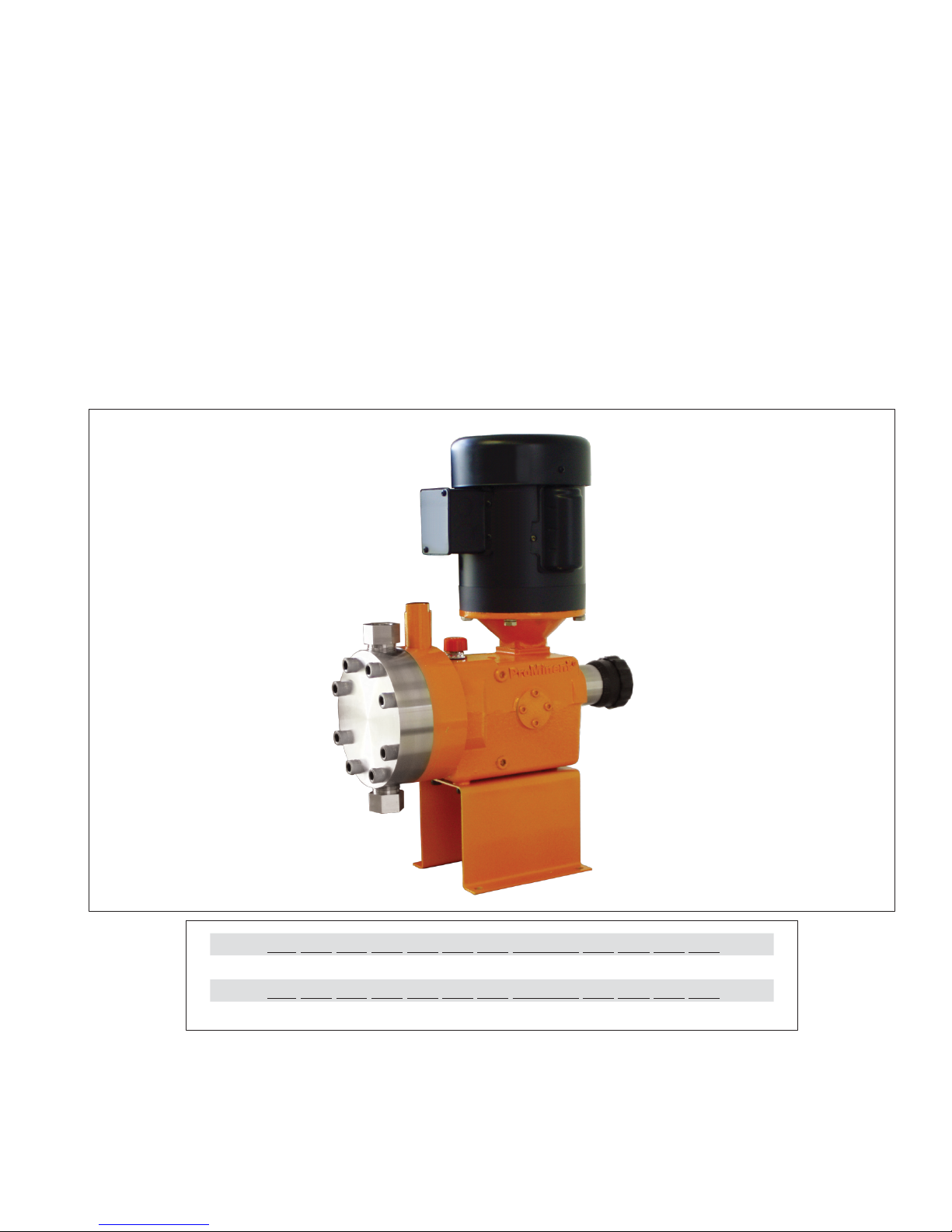
ProMinent® ProMus Series
Metering Pumps
!
!
ProMusOM_US.indd (ProMus_US_6_5_2012.pdf): Rev 1 - P/N. 7500436
!
!
!
!
!
!
!
!
!
!
!
!
!
!
!
!
!
!
!
!
!
!
!
!
!
!
!
!
!
!
!
!
!
!
!
!
!
!
!
Please enter identity code of the device here
!
!
Please completely read through the operating instructions first! Do not discard!
The warranty shall be invalidated by damage caused by operating errors!
!
!
!
!
!
ProMinent Fluid Controls, Inc. (USA) 136 Industry Drive, Pittsburgh, PA 15275
Page 2

Publishing details
ProMinent
Page 2
!
!
!
!
!
!
!
!
!
!
!
!
!
!
!
!
!
!
!
!
!
!
!
!
!
!
!
!
!
!
!
!
!
!
!
!
!
!
!
!
!
!
!
!
Publishing details:
!
Operating Instructions
ProMinent® ProMus Series Metering Pumps
© ProMinent Fluid Controls, Inc. (USA)
!
!
ProMinent Fluid Controls, Inc. (USA)
136 Industry Drive, Pittsburgh, PA 15275
Tel: 412.787.2484
Fax: 412.787.0704
eMail: sales@prominent.us
www.prominent.us
!
Subject to technical modifications
Printed in USA
Page 3

Table of contents
ProMinent
Page 3
!
!
!
!
Contents
!
1. About This Pump 6
!
2. Safety 6
!
3. Storage, Transport And Unpacking 9
!
3.1 Storage 9
!
3.2 Transport 9
!
3.3 Unpacking 9
!
4. Functional description 10
!
4.1 General Description ....................................................................................................... 10
!
4.2 Major Sub Assemblies (Figure 1)................................................................................... 10
!
4.2.1 The Power End Sub Assembly (Figure 2)...................................................................... 10
!
4.2.2 The Stroke Adjuster Sub Assembly (Figure 2) .............................................................. 10
!
4.2.3 The Hydraulic End Sub Assembly (Figure 2)................................................................. 10
!
4.2.3.1 Internal Relief/air Bleed Valve (Figure 2) ...................................................................... 10
!
4.2.3.2 Oil Replenishment Valve (Figure 2) .............................................................................. 11
!
4.2.3.3 Replenishment Check (Figure 2) .................................................................................. 11
!
4.2.4 The Liquid End Sub Assembly (Figure 2) ..................................................................... 11
!
5. Device Overview / Control Elements 14
!
6. Assembly 22
!
7. Installation 22
!
7.1 Installation: Hydraulic ..................................................................................................... 22
!
7.2 Installation: Electrical ..................................................................................................... 22
!
8. Commissioning 23
!
9. Operation 24
!
10. Maintenance 24
!
11. Repair 27
!
12. Troubleshooting 27
!
13. Decommissioning And Disposal 28
!
14. Technical Data 30
!
14.1 Capacity Data: ............................................................................................................... 31
!
14.2 Capacity Data: ProMus Low Flow Pumps only............................................................. 32
!
15. General Specifications for Electric Stroke Positioner 46
!
16. Declaration of Conformity: 48
Page 4

ProMinent
Page 4
!
!
Product Identification / Identity Code
!
Please enter the identity code given on the device label into the grey boxes below.
!
ProMus1
Pump Version:
17A
Size 17 liquid end with 3/8"
Plunger
30C
Size 30 liquid end with 1-1/8" Plunger
17B
Size 17 liquid end with 7/16" Plunger
40A
Size 40 liquid end with 1-3/4" Plunger
30A
Size 30 liquid end with 5/8"
Plunger
40B
Size 40 liquid end with 2" Plunger
30B
Size 30 liquid end with 13/16" Plunger
40C
Size 40 liquid end with 2-1/4" Plunger
Liquid end material:
SS1
316 Stainless steel Single ball check
SS2
316 Stainless steel Double ball check (*Needed for applications above 500 psi)
SS3
316 St. steel Single inlet, Double outlet (Rcmd. for Flooded suction w/ discharge pressure above 500 psi)
PVT
PVDF/PTFE size 17 Double inlet & outlet; sizes 30/40 Single inlet & outlet
Connectors:
0 NPT 1
BSP
taper
7 MNPT PVDF Standard (PVT LE only)
Gear ratio:
1
12.5:1
56C
2
15:1 56C
3 30:1 56C
4
40:1 56C
5
50:1 56C
6 12.5:1 IEC (IEC 71 with B5 flange)
7
15:1 IEC (IEC 71 with B5 flange)
8
30:1 IEC (IEC 71 with B5 flange)
9 40:1 IEC (IEC 71 with B5 flange)
10
50:1 56C IEC (IEC 71 with B5 flange)
11
100:1 (17A 3/8 plunger only) 56C
Motor:
X
No motor included
D Standard motor (1/2 HP, 115V, single phase, TEFC, NEMA 56C
Base:
0
Standard Base
Stroke Adjustment:
1
Manual stroke adjustment
7
Explosion proof NEMA 7
Internal relief valve:
A
3500 psi/size 17
B 2080 psi/size 17
C
1230 psi/size 17
D
640 psi/size 17
E 300 psi/size 17
F
2080 psi/size 30
G
1230 psi/size 30
H 640 psi/size 30
I
265 psi/sizes 30 & 40
J
200 psi/sizes 30 & 40
K 160 psi (30B, C & 40)
Hydraulic oil:
0
Standard
ProMus1
17A
SS1 0 1 X 0 1 A 0
Page 5
ProMinent
Page 5
!
!
!
General User Instructions / Operating Instructions
!
General User Instructions
!
Please read through the following user instructions! They will enable you to gain the maximum
benefit from the operating instructions manual.
!
The following items are particularly highlighted in the text:
!
• Enumerated points
!
• Highlighted points
!
Operating instructions:
!
!
!
NOTE
!
Guidelines are intended to make your work easier.
!
!
!
Safety Guidelines:
!
!
!
WARNING
!
Describes a potentially dangerous situation. If not avoided, could jeopardize life and/or cause
serious injury.
!
!
CAUTION
!
Describes a potentially dangerous situation. If not avoided, could result in lesser injuries or
damage to property.
!
!
IMPORTANT
!
Describes a potentially damaging situation. If not avoided, could result in damage to property.
!
!
!
!
In the event of complaint or a request for spare parts, quote the identity code and the serial
number, which you will find on the device label. This will enable clear identification of the pump
type and material variant.
Page 6

ProMinent
Page 6
!
!
About This Pump / Safety
!
1. About This Pump
!
The ProMinent ProMus is a metering pump using a flat, hydraulically actuated teflon diaphragm.
A typical pump assembly includes an electric motor, gear case, hydraulic unit, and liquid end. An
oil replenishment valve and poppet relief value maintain fluid volume in the hydraulic piston to
transfer reciprocating motion to the diaphragm.. A locking stroke adjuster limits piston movement
to control flow rates from 0% to 100% in 1% increments for metering fluids into most process
systems.
!
The ProMus achieves different pumping capacities by using 5 different gear ratios and 8 different
hydraulic piston diameters. Liquid ends are fabricated with Stainless Steel, Alloy 20, Hastelloy C
and PVDF. The diaphragm and dosing head seals are teflon.
!
!
2. Safety
!
!
Correct Use Of The Pump
!
• This pump may only be used to meter liquids.
!
• Operate the pump only within the conditions described in the technical data.
!
• General restrictions with regard to viscosity limits, chemical resistance and density must be
observed (refer to ProMinent® chemical resistance list in the catalog or at www.prominent.com)
!
• All other applications and modifications are prohibited.
!
• The pump must not be operated in hazardous areas unless motor, electric stroke control
and any other electrical components and wiring comply with the National Electric Code and
other applicable codes. Refer to articles 500 through 510 of the National Electric Code for
requirements to prevent fire or explosion caused by flammable gases or vapors, flammable
liquids, combustible dust, or ignitable fibers or filings.
!
• This pump is not suitable for metering gaseous media or solids.
!
• This pump may be used only within the stated pressure range.
!
• All users must read and observe this operating instruction manual.
!
• The pump must be operated by appropriately trained and authorized personnel.
!
Safety Guidelines:
!
!
WARNING
!
!
• The pump operates whenever the motor is energized; always take precautions to
avoid personal injury or hazards from unexpected startup of the motor.
!
• Lock out pump motor before performing any maintenance on pump or pump system.
!
• Lock out the pump motor following a power failure if such interruptions in pump function
would create a hazard or cause damage to components.
!
• Periodically inspect for chemical leaks since this pump and its discharge operate
continually under high pressure system leaks may develop over time.
!
• Always de-pressurize the liquid end before performing any maintenance on the pump or
system.
!
• Always empty and rinse pump liquid end before maintenance activities.
!
• Always wear appropriate protective equipment with performing pump maintenance.
!
• Make pump accessible at all times for necessary operating and maintenance activities.
Page 7

ProMinent
Page 7
!
!
Safety
!
!
• Periodically inspect the breather vent of the pump. If spillage occurs from this area
immediately turn off the pump. Follow maintenance procedures to replace the diaphragm.
• If the diaphragm becomes ruptured then chemical may enter the gearbox and mix with
hydraulic oil and spill through the breather vent onto the surroundings. Follow
maintenance procedures to replace the diaphragm.
• If the chemical being pumped is corrosive to carbon steel and brass and the diaphragm
ruptures then the internals of the pump will be damaged. Remove the pump from
service using all appropriate safety precautions and follow maintenance procedures. !
!
Safeguards
!
• An internal relief valve is part of the hydraulic system. The sole purpose of the relief valve
is to protect the driver subassembly from overload in the event of excessive pressure of the
pumped fluid. It can never be used to protect the system from overload. An external bypass
valve must always be used to protect the system from over pressure.
!
• The internal relief valve has been adjusted at the factory to 10% greater than the value listed
in the ident code. Under normal operating conditions it is not necessary to adjust the internal
relief valve. When the adjusting screw is rotated, record the number of turns the screw has
been changed from the value set at the factory. Record the number of turns every time the
screw is adjusted to be able to revert to factory setting if necessary.
!
Testing the internal relief valve
!
• The pump must be running to test the internal relief valve.
!
• A suitably rated external bypass valve must always be used to protect system from system
over pressurization.
!
• The Promus pump comes with a “Relief/Air Bleed observation port” (see outline drawing).
!
• When the pump is operating under normal conditions a pulsing “heartbeat” action is
observed. A barely perceived net out flow of oil is observed.
• When the pump is operating under upset conditions (internal relief) the properly operating
relief valve will bypass large amounts of oil on every pump stroke limiting the pressure that
the pump will develop. Oil flow as observed in the observation port will be pulsing in
nature. Do not remove the observation port under these circumstances.
!
• To test the internal relief, slowly increase the system pressure until 10% greater than the
value listed in the Ident code. It may not be possible to reach this pressure if the pump is in
internal relief. If this condition exists, slowly rotate the adjusting screw clockwise until the
set pressure is reached and the pump is still relieving. If the pump is not in relief at the 10%
greater than value listed in the Ident code rotate the adjusting screw counterclockwise until
the pump goes into relief and the desired set pressure is maintained.
Page 8

ProMinent
Page 8
!
!
Storage, Transport and Unpacking
!
!
Indicator to Safety Declaration:
!
WARNING
!
Only send the equipment for repair or maintenance in a cleaned condition and with the liquid end
flushed. However, should any safety precautions be necessary even after careful draining and
cleaning of the equipment, the required information must be listed in the Safety Declaration! The
Safety Declaration forms part of the inspection/repair contract. Maintenance or repair work will
only be carried out if a Safety Declaration - correctly and fully completed by an authorized and
qualified member of the Operator’s staff - is available.
!
!
!
CAUTION
!
• It is not permitted to assemble and install ProMinent® pumps using non-ProMinent parts
unless approved and recommended by ProMinent. This could lead to damage or injury.
!
• When metering corrosive liquids, check the resistance of the pump materials (see
ProMinent® resistance list in the product catalog).
!
• The installation, operation and maintenance of ProMinent pumps may be subject to
regulations set by state and federal agencies depending upon environmental conditions and
the fluid being handled. Consult your safety professional for any special regulations regarding
the fluids being handled or environmental conditions.
!
Sound Intensity Level:
!
The sound intensity level is < 70 dB
Page 9
ProMinent
Page 9
Functional Description
!
!
!
3. Storage, Transport And Unpacking
!
!
!
IMPORTANT
!
The pump is filled with oil if it is supplied with a liquid end.
!
Ambient conditions for storage and transport:
!
Temperature: 14°F to 122°F (-10°C to 50°C)
Air humidity: max. 95 % relative humidity, non-condensing
!
!
ProMus weights in Lbs. (Kgs)
Liquid End
Size
Less Motor & Actuator
With Motor only
With Actuator &
Motor
With Actuator
only
Metal
17 A & B
49(22.2)
78(38.4)
95(43.1)
66(29.9)
Metal
30 A, B & C
58(26.3)
87(39.5)
104(47.2)
75(34.0)
Metal
40 A, B &C
68(30.8)
97(44.0)
114(51.7)
85(38.6)
Plastic
17 A & B
48(21.7)
77(34.9)
94(42.6)
65(29.5)
Plastic
30 A, B & C
54(24.5)
83(37.6)
100(45.4)
71(32.2)
Plastic
40 A, B &C
60(27.2)
89(40.4)
106(48.4)
77(34.9)
!
!
3.1 Storage
!
• Prepare the pump for storage by flushing all chemicals from the liquid end and replacing the
oil breather cap (orange) with the shipping plug (no color specified).
!
• Store in original shipping container if possible.
!
• Store pump in upright position in a dry, dust-free environment.
!
!
3.2 Transport
!
• Replace oil breather cap (orange) with shipping plug (no color specified) for transit.
!
• Transport in original container or container that will keep pump upright.
!
!
3.3 Unpacking
!
• Inspect package before unpacking. If package is found to be damaged, notify shipping
company immediately
!
• After unpacking, mount pump on a secure, level surface.
!
• Save the shipping plug (no color specified) and shipping container for possible future storage
or transit.
Page 10

ProMinent
Page
Functional Description
!
!
!
!
4. Functional description
!
!
4.1 General Description
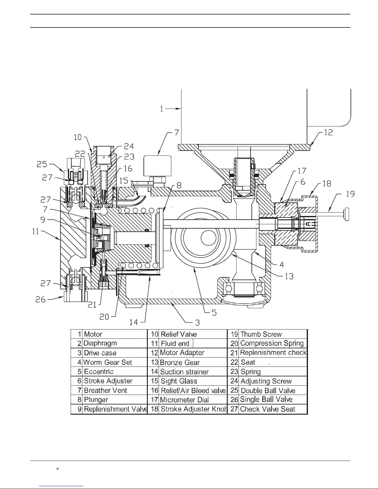
The Prominent ProMus is an electric motor (1) driven lost motion metering pump incorporating a
hydraulically balanced Teflon (2) diaphragm. The drive case (3) is cast iron incorporating a worm gear
set (4) (5 Ratios available) driving a rotating eccentric (5). The locking stroke adjuster (6) varies the flow
from 100% to 0% in 1% increments. The hydraulic end transfers the rotating eccentric (5) motion to the
diaphragm (7) (three sizes) movement by way of a reciprocating plunger (8) (8 plunger diameters available).
The plunger (8) and diaphragm (7) are hydraulically coupled (no mechanical connection). Coupling
compliance is precisely controlled by a mechanically actuated replenishment valve (9), which senses
diaphragm (7) position to admit coupling fluid as required. The coupling fluid is automatically degassed
to maintain accuracy and drive case is protected from overload by a simple acting relief valve (10). The
hydraulic end is separated from the fluid end by a Teflon (7) diaphragm completely isolating the pumped
fluid from the surroundings. The fluid end (11) is available in Stainless Steel, Alloy 20 Hastelloy C and
PVDF. All fluid end seals are Teflon.
!
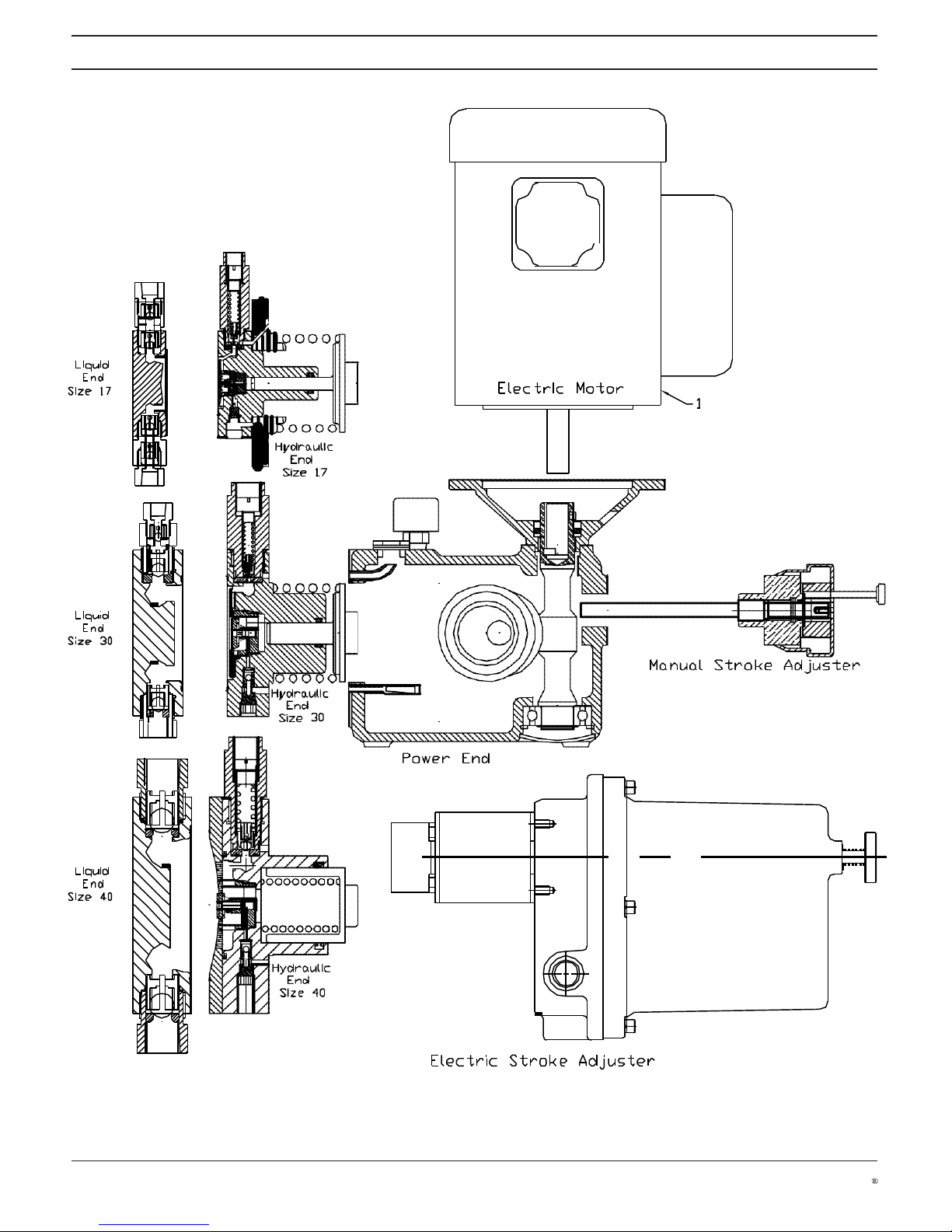
4.2 Major Sub Assemblies (Figure 1)
!
The pump is divided into four major sub assemblies. They are the Power End, the Hydraulic End, the
stroke adjuster and the Liquid End. The Stroke Adjuster can be either manual or electric. There are three
Hydraulic ends that can mate with the single Driver end. The three Liquid Ends correspond with three
diaphragm sizes. The three Liquid ends are designated Size 17, Size 30 and Size 40 to reflect the working
diameter of the diaphragms.
!
4.2.1 The Power End Sub Assembly (Figure 2)
!
The pump is driven by an electric motor (1). The standard frame size is Nema 56c. An IEC 71 frame is
available by specifying a motor adapter (12) and worm that mate with the IEC motor. The motor (1) is
close coupled to the worm (4). A hardened steel worm (4) and a bronze worm gear (13) reduce the speed
of the motor (1). Five ratios are available. 12.5:1, 15:1, 30:1, 40:1 and 50:1. The stroke speeds are 138/
min, 115/min, 58/min, 43/min and 35/min at 1725 RPM and 116/min, 97/min, 48/min, 36/min and 29/min at
1450 RPM. Simple Harmonic motion is generated by way of a rotating eccentric assembly (5). A needle
cage and roller assembly allows for the rolling action of the outer race of the eccentric assembly. This
rolling action minimizes the both the wear and the heat generated at the Eccentric Assembly (5) Plunger
(8) interface. The cast iron drive case (3) serves as a support for the worm, the eccentric assembly and
eccentric support shaft. It also doubles as an oil reservoir for the hydraulic end The oil in the reservoir also
serves as the lubricant for the gear set and bearings. A suction strainer (14) is part of the drive case (3). It
removes particulate before it enters the hydraulic end. A sight tube (15) for observing oil flow from the relief
/air bleed valve (16) is also part of the drive case (3).
!
4.2.2 The Stroke Adjuster Sub Assembly (Figure 2)
!
The 10-turn stroke adjuster (6) provides for lost motion pump flow control by holding the plunger (8) away
from the eccentric assembly (5). It continuously adjusts the pump flow from 0% to 100%. A micrometer dial
(17) indicates the % setting in 1% increments. The pump stroke is .787 inches (20 millimeters). The manual
stroke adjuster knob is locking by way of a thumbscrew.
!
An electric actuator is also available accepting 4 to 20 mA control signals for remote flow control. The
actuator are close coupled to the pump and do not require an additional base.
!
4.2.3 The Hydraulic End Sub Assembly (Figure 2)
!
The hydraulically balanced system is separated from the process fluid by a flat uniform thickness
Teflon diaphragm (7). The reciprocating motion of the plunger (8) is transferred to the diaphragm (7)
by hydraulic oil. There is no mechanical connection between the diaphragm (7) and the plunger (8). A
compression spring (20) provides the force to return the plunger (8) on the suction stroke. There are three
subassemblies in the Hydraulic End. The relief/air bleed valve (16), the oil replenishment valve (9) and the
oil replenishment check (21).
!
4.2.3.1 Internal Relief/air Bleed Valve (Figure 2)
An adjustable relief valve is part of the hydraulic system. The sole purpose of the relief valve is to protect
the drive subassembly from overload in the event there is excessive pressure of the pumped fluid. A
poppet (16) is held against a replaceable seat (22) by a spring (23). The tension in the spring is adjustable
by an adjusting screw (24). When the force of the spring is exceeded by the hydraulic pressure acting at
the seat area, the poppet (16) lifts allowing oil to escape back to the reservoir. Included in the poppet (16) is
an air bleed valve. The purpose of the air bleed valve is to allow entrained air to escape from the hydraulic
Page 11

Functional Description
ProMinent
Page 11
!
!
!
!
oil. The relief/air bleed valve is located at the high point of the hydraulic system. Air that comes out of
solution migrates to this high point and is automatically allowed to escape via the air bleed system.
The air bleed is comprised of two simple opposing check valves vertically mounted in the poppet. On
the pressure stroke the ball travels to the upper seat allowing air and oil to pass during the transit time.
As the ball seats the hydraulic system is sealed and pumping action begins. On the suction stroke the
ball returns to the lower seat and again seals allowing plunger to return the diaphragm.
!
4.2.3.2 Oil Replenishment Valve (Figure 2)
The replenishment valve (9) admits oil to the hydraulic system that is lost through the air bleed valve.
A precise volume of oil must be maintained to insure pumping accuracy. The valve senses the position
of the diaphragm (7) and admits oil when low. The system reaches a state of equilibrium so that a
constant volume of oil is maintained.
!
4.2.3.3 Replenishment Check (Figure 2)
!
A check valve (21) is required on the inlet to the hydraulic system to prevent back flow from the
hydraulic system to the reservoir during the pumping stroke.
!
4.2.4 The Liquid End Sub Assembly (Figure 2)
!
The liquid end (11) is available in 316SS, Alloy 20 and Hastelloy C. The design for all metallic material
offerings is the same. The Size 17 and Size 30 liquid end is available in double ball (25) as well as
single ball (26) configurations. Removable seats are standard on both size 17 and size 30. A PVDF
Liquid end is also available
Page 12
Functional Description
ProMinent
Page 12
!
!
!
Figure 1
Page 13
Functional Description
ProMinent
Page 13
!
!
!
!
Figure 2
!
!
!
!
!
!
!
!
!
!
!
!
!
!
!
!
!
!
!
!
!
!
!
!
!
!
!
!
!
!
!
!
!
!
!
!
!
!
!
!
!
!
!
!
!
!
!!!
!
!
!
! !!!
! !!! ! ! ! !
!
!!! !!!!!!!!!!!!!!!!! !
!
!!!
!
Page 14
ProMinent
Page 14
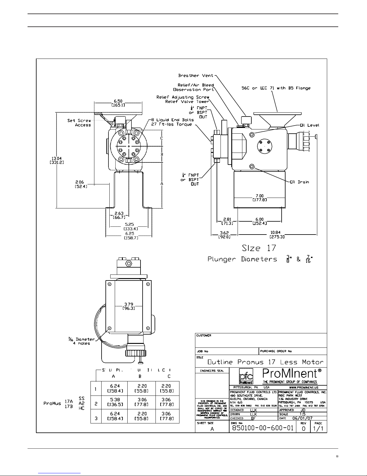
5.
Device Overview / Control Elements
!
!
!
Dimensional Drawing / ProMus Size 17 Metal Liquid End
!
!
!
!
!
!
!
!
!
!
!
!
!
!
!
!
!
!
!
!
!
!
!
!
!
!
!
!
!
!
!
!
!
!
!
!
!
!
!
!
!
!
!
!
!
!
!
!
!
!
!
!
!!!
!!!
!
!!!
!
!!!
!
Page 15
ProMinent
Page 15
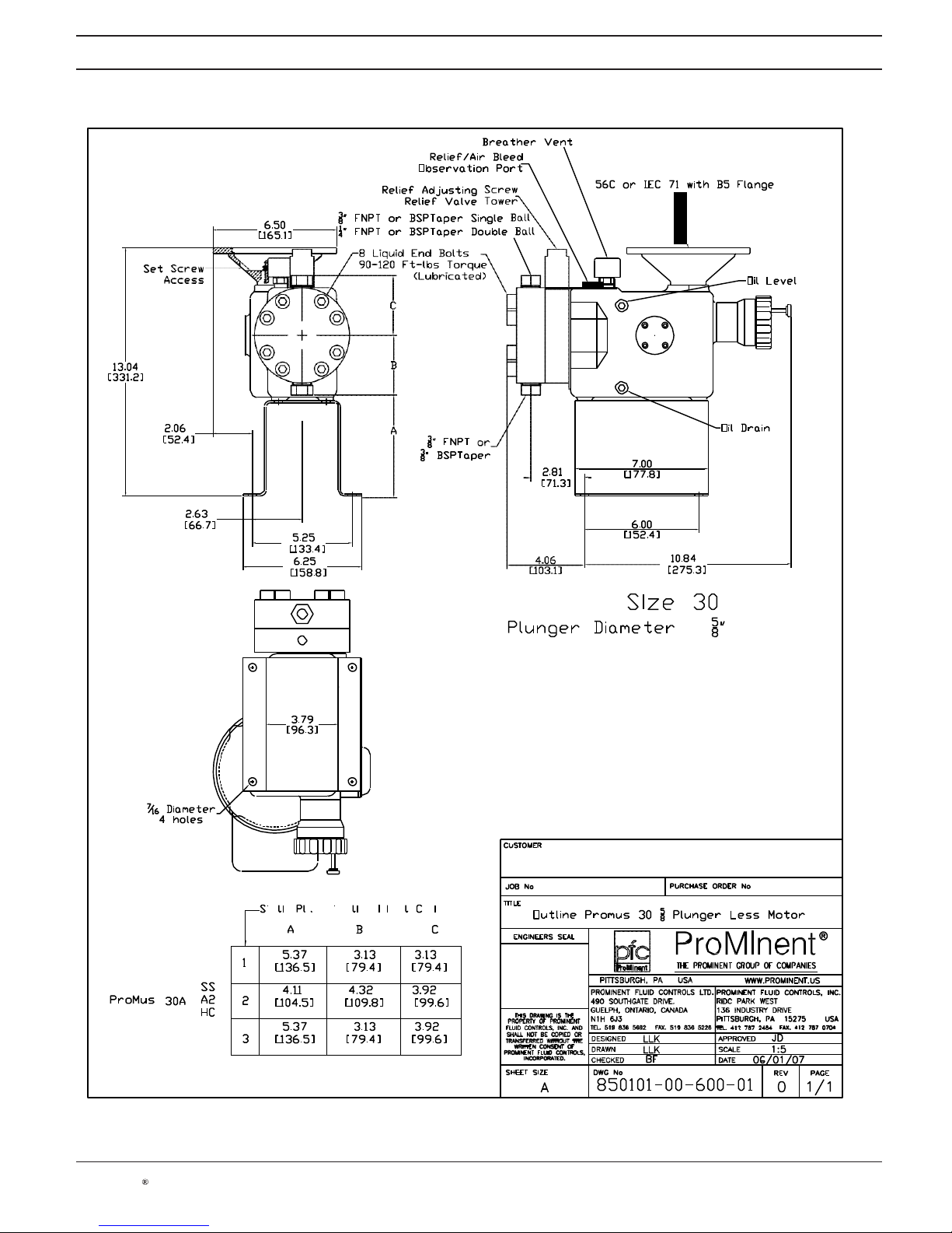
5.
Device Overview / Control Elements
!
!
!
Dimensional Drawing / ProMus Size 30A Metal Liquid End
!
!
!
!
!
!
!
!
!
!
!
!
!
!
!
!
!
!
!
!
!
!
!
!
!
!
!
!
!
!
!
!
!
!
!
!
!
!
!
!
!
!
!
!
!
!
!
!
!
!
!
!
!!!
!!!
!
!!!
!
!!!
!
Page 16

ProMinent
Page 16
5.
Device Overview / Control Elements
!
!
!
Dimensional Drawing / ProMus Size 30B & C Metal Liquid End
!
!
!
!
!
!
!
!
!
!
!
!
!
!
!
!
!
!
!
!
!
!
!
!
!
!
!
!
!
!
!
!
!
!
!
!
!
!
!
!
!
!
!
!
!
!
!
!
!
!
!
!
!
!
!!!
!
!!!
!
!!!
!
!!!
Page 17

ProMinent
Page 17
5.
Device Overview / Control Elements
!
!
!
Dimensional Drawing / ProMus Size 40 Metal Liquid End
Page 18

ProMinent
Page 18
5.
Device Overview / Control Elements
!
!
!
Dimensional Drawing / ProMus Size 17 Plastic Liquid End
!
!
!
!
!
!
!
!
!
!
!
!
!
!
!
!
!
!
!
!
!
!
!
!
!
!
!
!
!
!
!
!
!
!
!
!
!
!
!
!
!
!
!
!
!
!
!
!
!
!
!
!
!
!
!!!
!!!
!
Page 19

ProMinent
Page 19
5.
Device Overview / Control Elements
!
!
!
Dimensional Drawing / ProMus Size 30 Plastic Liquid End
!
!
!
!
!
!
!
!
!
!
!
!
!
!
!
!
!
!
!
!
!
!
!
!
!
!
!
!
!
!
!
!
!
!
!
!
!
!
!
!
!
!
!
!
!
!
!
!
!
!
!
!
!
!
!
!
!
!!!
!
!!!
Page 20

ProMinent
Page 20
5.
Device Overview / Control Elements
!
!
!
Dimensional Drawing / ProMus Size 40 Plastic Liquid End
Page 21

ProMinent
Page 21
5.
Device Overview / Control Elements
!
!
!
Dimensional Drawing / ProMus Size Electric Actuator
Page 22

ProMinent
Page 22
!
!
Assembly/ Installation
!
6. Assembly
!
The ProMus pump is shipped complete from ProMinent and no assembly is required. A shipping
plug must be removed from the oil fill/breather vent hole and replace with the supplied orange
breather/ vent. The pump comes filled with oil.
The whole pump must be screwed onto a level and stable surface. For this purpose fasten the
pump with four screws (3/8 Inch or M10 Diameter Bolts and washers) through the four holes in
the base.
!
!
7. Installation
!
7.1 Installation: Hydraulic
!
!
WARNING
!
• If the pump is to be used with chemicals that are reactive with water, be sure to remove any
residue that may remain from factory testing. Feed low-pressure compressed air through the
suction valve to purge water from the liquid end.
!
• For Hazardous locations an external pressure relief valve must be installed downstream from
the liquid end to avoid potential hazards caused by blockage in the discharge line. In some
environments, heat generated by excessive fluid passing through the internal relief value may
cause temperatures of the pump housing to reach high levels.
!
!
IMPORTANT
!
For chemicals with a particle size greater than 0.01 in. (0.3 mm), install a strainer in the suction
line.
!
!
NOTE
!
If the metering pump discharges to atmospheric pressure, install a backpressure valve to create
a minimum backpressure of approximately 21.8 psi (1.5 bar).
!
Maximum admissible priming pressure (suction side): 14.5 psi (1 bar).
Viscosity limits maximum 200 mPa-s (200 cP).
7.2 Installation: Electrical
!
!
IMPORTANT
!
Motor
!
• For safe operation in hazardous environments, all electrical components, including motor,
electric stroke control and other devices must be rated for hazardous areas as described in
the National Electric Code.
!
• Articles 500 through 510 of the National Electric Code cover the requirements for electrical
equipment and wiring when flammable gases or vapors, flammable liquids, combustible dust,
ignitable fibers, or flying may create fire or explosion hazards.
• Connect the motor using the information provided on the motor nameplate. Motor rotation
should be counter clockwise looking down on motor (fan end). Also, read and follow
additional instructions in manuals provided with the motor.
!
• For pumps with an electric stroke adjuster, follow any supplemental instructions provided for
making electrical connections and operating the unit.
Page 23

ProMinent
Page 23
!
!
Commissioning
!
8. Commissioning
!
!
IMPORTANT
!
• Before commissioning the pump, check that the breather/vent has been installed. The pump
will not operate correctly unless the breather vent has been installed. A shipping plug is
installed in the breather/ vent hole to prevent oil spillage since the pump comes filled with oil.
Remove the shipping plug and replace with the breather/ vent supplied.
!
• Check that pump capabilities are not exceeded when metering highly viscous or dense
chemicals.
!
• Check that liquid end materials are chemically resistant to the metered fluid (see the
resistance list on line at www.prominent.us or the latest catalog)
!
• The pump can not be operated other than in the way described in the “Technical data”
!
• For chemicals with a particle size greater than 0.01 in (0.3mm), it is imperative that a filter is
installed in the suction line.
!
Venting the Liquid End
!
Venting the liquid end or suction against pressure:
!
WARNING
!
• Always depressurise the suction and discharge tubing before working on the pump!
!
• Always wear appropriate protective equipment when metering hazardous or unknown liquids!
!
approx. 300 g
!
!
!
!
!
Brass rod
9 Ø x
approx. 200 mm
!
!
!
!
!
!
!
!
Figure 3
Priming the liquid end
!
1. Detach the discharge tubing
!
2. Install a section of transparent tube
!
3. Run the pump slowly until chemical appears in the transparent tube section
!
4. Detach the transparent tube
!
5. Attach the discharge tubing
!
!
GUIDELINE on valve installation:
!
If experiencing priming problems during installation, place the valve on a stable surface and tap
the ball seat lightly with a brass rod and an approx. 1/2 lb (250 g) hammer. Prime valves when
damp (See fig. 3).
!
!
!
!
The pump is now ready to operate.
Page 24

ProMinent
Page 24
!
!
Operation/Maintenance
!
!
9. Operation
!
!
WARNING
!
Observe the instructions in “Commissioning” section.
!
!
IMPORTANT
!
In the event of an electrical fault there is danger of burns from a hot power end.
!
!
• The Pump output can be adjusted using a mechanical or electronic stroke adjuster mounted
on the pump.
!
!
10. Maintenance
!
!
!
WARNING
!
• Pumps and peripherals are to be maintained and repaired by trained and authorised
personnel only!
!
• Always depressurise the suction and discharge tubing before working on the pump!
!
• Always empty and rinse the liquid end before maintenance and repair work, if used with
hazardous or unknown materials!
!
• When working on the liquid end, wear appropriate protective equipment when metering
hazardous or unknown liquids!
!
• Before working on the motor, switch off and protect from unauthorised reconnection!
If external fan, stroke position motor or speed controller switch off also!
Check that motor is voltage free!
!
!
NOTE
!
• Keep a set of spare parts in stock for maintenance work on each liquid end.
!
Maintenance tasks
!
After Three Months
!
A shorter maintenance interval may be required for systems under heavy load (e.g. continuous
operation, high system pressures, or abrasive media).
!
!
• Check torque of the liquid end bolts and re-torque if necessary.
!
Ident code 17A & 17B Metal Liquid Ends Only 30 lbf-ft (36 Nm)
!
Ident Code 30A,30B & 30C Metal Liquid Ends Only 80 lbf-ft (122-163 Nm)
Ident Code 40A,40B & 40C Metal Liquid Ends Only 80 lbf-ft (122-163 Nm)
Ident code 17A & 17B Plastic Liquid Ends Only 20 lbf-ft (27 Nm)
Ident Code 30A,30B & 30C Plastic Liquid Ends Only 30 lbf-ft (41 Nm)
Ident Code 40A,40B & 40C Plastic Liquid Ends Only 30 lbf-ft (47 Nm)
Page 25

ProMinent
Page 25
!
!
Maintenance
!
!
• Check discharge and suction valves for chemical leakage
!
• Check system accessories for correct operation and related connections and fittings for
chemical leakage.
!
• Check the oil level in the pump drive case.
!
• Check pump feed rate using calibration column if available. Changes in feed rate indicate the
need for pump maintenance or system problems.
!
After Approximately 5000 Operating Hours:
!
Change the hydraulic oil.
!
!
WARNING
!
• Hot hydraulic oil presents a risk of burning. Avoid contact with draining oil.
!
• Gear oil: Mobilube 1 SHC 75W-90, or equal
!
• Oil quantity: 1.5 quart (1.43 liter)
!
Changing The Hydraulic Oil:
!
1. Remove the breather vent.
!
2. Place an oil disposal container under the drain plug.
!
3. Unscrew the drain plug.
!
4. Drain the oil from the drive case.
!
5. Remove the oil level plug
!
6. Replace the drain plug
!
7. Refill with oil until the oil overflows the bottom of the oil level hole
!
8. Replace the oil level plug
!
9. Replace the breather vent
!
After Approximately 10,000 Operating Hours:
!
Change the diaphragm. Useful life of the diaphragm may vary depending upon system
backpressure, operating temperatures, stroke length and frequency, and pump chemical
characteristics.
!
!
IMPORTANT
!
The diaphragm can never be reused once it is removed from the pump.
!
TO BE USED ONLY AFTER THE DIAPHRAGM HAS BEEN REMOVED
OR CHANGED DURING MAINTENANCE. THIS PROCEDURE DOES NOT
APPLY FOR NEW OR FACTORY REBUILT PUMPS.
Changing The Diaphragm:
!
Change the diaphragm as follows
!
1. Disconnect the inlet and outlet piping from the pump
!
2. Remove the breather vent.
!
3. Place an oil disposal container under the drain plug.
!
4. Unscrew the drain plug.
!
5. Drain the oil from the drive case.
Page 26

ProMinent
Page 26
!
!
Maintenance
!
!
6. Place an oil container under the liquid end
!
7. Loosen the liquid end bolts.
!
8. Allow the oil to drain from the plunger body.
!
9. Remove the liquid end.
!
10. Remove the old diaphragm and discard.
!
11. Insert the new diaphragm in the counter bore of the liquid end.
!
12. Reinstall the liquid end taking care that the diaphragm stays in the counter bore
!
13. Tighten the liquid end bolts to the specified torque.
!
14. Replace the oil drain plug
!
15. Refill with oil until the oil just overflows the bottom of the oil level hole.
!
16. Replace the oil level plug
!
17. Replace the breather vent
!
!
IMPORTANT
!
The pump must be primed before it is returned to service under system
pressure. If the liquid end does not contain media when placed under
pressure, damage to the diaphragm may occur.
!
Priming the hydraulic system
!
1. Connect suction tubing.
!
2. Install a section of transparent tubing to the discharge.
!
Note: It is recommended to vent the liquid end using process fluid.
!
3. Remove the adjusting screw counting the number of turns.
!
4. Record the number of turns to remove the adjusting screw
!
5. Remove the spring the washer and the relief valve poppet,
!
6. Turn on the pump and turn the stroke to 50%
!
7. While the pump is running, slowly add small amounts of hydraulic fluid into the relief tower.
You will notice that the air in the system will be discharged on the compression stroke. Once
the Hydraulic system is full you will notice that the hydraulic oil will rise and fall in the tower.
!
8. Turn off the pump.
!
9. Reinstall the relief poppet the washer the spring and the adjusting screw.
!
10. Turn the adjusting screw until it just touches the spring and back it off one complete turn.
!
Note: This causes the poppet rise and fall, releasing any excess hydraulic oil back to the
drive case. If the hydraulic side is over primed this will allow the hydraulic oil to be relieved
without rupturing the diaphragm towards the liquid end side. Allow the pump to run for a few
minutes.
!
11. Start the pump
!
12. Be sure that there is a flow of air of fluid being released from the discharge.
!
13. After discharge fluid is noticed, turn the adjusting screw clock wise one full turn after it
touches the valve spring.
!
14. Turn the pump off
!
15. Install the discharge line.
!
16. Restart the pump
Page 27

ProMinent
Page 27
!
!
Maintenance / Repair/ Troubleshooting
!
17. Slowly apply back pressure on the process side of the pump until the pump is in full internal
relief. (Gushing/Pulsing oil will be visible in the Relief/Air Bleed Observation Port when the
pump is in full internal relief)
!
Note: Allow the pump to relieve until the air is purged from the hydraulic system.
!
18. Gradually turn down the adjusting screw counting the number of turns until the recorded
value in step 4 above.
!
19. Slowly increase the pressure until the system pressure is reached.
!
20. To test the internal relief, slowly increase the system pressure until 10% greater than the
value listed in the Ident code. It may not be possible to reach this pressure if the pump is in
internal relief. If this condition exists, slowly rotate the adjusting screw clockwise until the
set pressure is reached and the pump is still relieving. If the pump is not in relief at the 10%
greater than value listed in the Ident code rotate the adjusting screw counterclockwise until
the pump goes into relief and the desired set pressure is maintained.
!
!
11. Repair
!
!
WARNING
!
• Pumps and peripherals are to be maintained and repaired by trained and authorised
personnel only!
!
• Always depressurise the suction and discharge tubing before working on the pump!
!
• Always empty and rinse the liquid end before maintenance and repair work, if used with
hazardous or unknown materials!
!
• When working on the liquid end, wear appropriate protective equipment when metering
hazardous or unknown liquids!
!
• Before working on the motor, switch off and protect from unauthorised reconnection!
If external fan, stroke position motor or speed controller switch off also!
Check that motor is voltage free!
!
!
IMPORTANT
!
Each time the liquid end is removed and the diaphragm is changed re torque the liquid end bolts
in a crosswise fashion to the value listed in Section 10 maintenance tasks
!
Rebuilding Inlet and outlet Check Valves
!
Clean and rebuild inlet and outlet check valves one at a time.
!
Refer to liquid end parts list for diagram and parts for rebuilding check valves (section 14)
!
• Disassemble valve
!
• Replace worn parts
!
• Clean the remaining parts
!
• Assemble the valve.
Page 28

ProMinent
Page 28
!
!
Troubleshooting/ Decommissioning and Disposal
!
12. Troubleshooting
!
!
!
WARNING
!
• Always wear appropriate protective equipment when working with hazardous chemicals
!
• Always depressurize the suction and discharge lines before working on the pump.
!
• Always empty and rinse the liquid end before maintenance and repair work!
!
Pump Fails To Meter Liquid To Pump Specification Pump Fails To Meter
Liquid To Pump Specification
!
or
!
!
Pump Does Not Prime Despite Full Stroke Action And Venting
!
Cause: Valves dirty or worn
Remedy: Overhaul valves (see "Overhaul valves", see "Repair" section)
!
Cause: Internal relief valve open (outlet pressure higher than internal relief valve setting)
Remedy: Reduce pressure in external backpressure valve
Cause: Internal relief valve heavily worn as discharge line blocked or constricted
Remedy: Replace external backpressure valve and remove blockage from discharge line
!
Cause: Hydraulic oil low
Remedy: Add hydraulic oil until oil level has reached inspection port on the side of the pump
housing (see "Replace Diaphragm":, "Maintenance" section)
!
Cause: Electrical connections to motor
Remedy: 1. Verify voltage and frequency
2. Check motor connections
!
!
!
Power End Motor Very Hot
!
Cause: Discharge line greatly constricted
Remedy: 1. Remove blockage from discharge line
2. Check external backpressure valve
!
!
13. Decommissioning And Disposal
!
!
Decommissioning
!
!
!
WARNING
!
• Pumps and peripherals are to be maintained and repaired by trained and authorised
personnel only!
Page 29

ProMinent
Page 29
!
!
Decommissioning and Disposal
!
!
• When decommissioning pump, the housing and particularly the liquid end should be cleaned
thoroughly to remove all dirt and chemicals!
!
• Always depressurise the suction and discharge tubing before working on the pump!
!
• Always empty and rinse the liquid end before maintenance and repair work, if used with
hazardous or unknown materials!
!
• When working on the liquid end, wear appropriate protective equipment when metering
hazardous or unknown liquids!
!
• Before working on the motor, switch off and protect from unauthorised reconnection!
!
• If external fan, stroke position motor or speed controller present, switch off also!
!
• Ensure that there is no voltage present at the motor!
!
• Ensure that pumps cannot be switched on by unauthorised personnel during maintenance
work!
!
• Avoid contact with draining oil since there is a risk of burning by hot hydraulic oil.
!
Final Decommissioning
!
• Disconnect pump from power supply
!
• Rinse the liquid end with a suitable cleaning agent, clean thoroughly if used with hazardous
materials
!
• Drain off hydraulic oil!
!
Temporary Decommissioning
!
Additionally:
!
• Place valve covers on valves
!
• Place the pump on a pallet if possible
!
• Cover the pump with a tarpaulin (allow ventilation!).
!
!
Store the pump in a dry enclosed area at:
!
Storage temperature: 14°F to 122°F (-10°C to 50°C)
!
Air humidity: max. 95 %, non-condensing
!
Disposal
!
!
IMPORTANT
!
Observe all current local, state/provincial and federal directives that apply to disposal of pumps,
pump components, and waste products. Give particular attention to waste oils and electronic
materials.
Page 30

ProMinent
Page 30
!
!
Technical Data
!
14. Technical Data
!
!
Priming Lift
!
The priming lift is 5 ft (1.5 m). (Determined for 68°F (20ºC) water with liquid end and suction line
empty and clean moistened valves). Flooded suction recommended for 100:1 (3/8 plunger only).
!
Suction Lift
!
The suction lift is 7.5 ft (2.3m) (Determined for 68°F (20ºC) water with liquid end and suction line
filled and a suction line with adequate cross section). Flooded suction recommended for 100:1
(3/8 plunger only).
!
Priming Pressure
The maximum allowable priming pressure is 14.5 psi (1 bar)
!
Internal Hydraulic Pressure Relief Valve
The internal relief valve is set to 10% over the pressures listed in the following chart.
!
Pump Accuracy
!
Steady state flow accuracy is +/- 1% over a turndown ratio of 10:1
!
The flow repeatability is +/- 3% over the specified turn down ratio.
!
Deviation from linearity does not exceed +/- 3% of the rated flow over the specified turn down
ratio
!
Viscosity
Viscosity limit without valve 200 mPa-s (200 cP)
!
Liquid End Materials of Construction
!
Material Liquid End Suct./Dis. Seals/ball seat Valve Balls
SS 316 SS 316 SS PTFE/SS stainless steel
A2 alloy 20 alloy 20 PTFE/A2 alloy 20
HC hastelloy C hastelloy C PTFE/HC hastelloy C
PVT PVDF PVDF PTFE/PVDF ceramic
!
Hydraulic Oil
!
Type Mobilube SHC 75w-90
Quantity 1.5 quarts (1.42 liters)
!
Ambient Conditions
!
Storage temperature 14°F - 122°F (-10°C to 50°C)
Ambient temperature 14°F - 104°F (-10°C to 40°C)
Air humidity max. 95% relative humidity, non-condensing
!
Maximum metering chemical temperatures for the liquid end depend
upon material type:
PVT SS, A2 & HC
Long term at max. back pressure 150°F (65°C)
194°F (90°C)
Short term at max. 30 psi (2 bar) 15 Min. 212°F (100°C) 248°F (120°C)
!
Environmental
Permissible air humidity 95% non- condensing
!
Chemical Resistance
See our latest product catalog or www.prominent.us.
Page 31

ProMinent
Page 31
!
!
!
!
psig
!
Bar !psig
!
Bar !U.S.
!
!
Stroke/
!
U.S !Stroke/
!
Max.
FNPT/
MNPT/
BSP
BSP
Plunger (in.)
(PVD
) (PVDF
) (metal)
(metal
) GPH
(l/h)
min.
GPH
(l/h)
min
Bar (metal)
(PVDF)
!
Capacity Data
!
14.1 Capacity Data
!
!
!
!
!
!
At 60 Hz (1750 rpm)
Capacity
!
Max.
At 50 Hz (1458 rpm)
Typical
at Max.
Gear
Stroke
Capacity at Max.
suct./dis.
!
Backpressure
Ratio
Rate
Backpressure
Connection
!
!
F
!
Size 17 3/8" 230 16 3500 241 0.2 (0.87) 100 18 - - - - - -
3/8" 230 16 3500 241 0.61 (2.3) 50 35 - - - - - -
3/8" 230 16 3500 241 0.76 (2.8) 40 43 0.63 2.45 36 241 1/4 1/4
3/8" 230 16 3500 241 1.02 (3.8) 30 58 0.85 3.29 48 241 1/4 1/4
3/8" 230 16 3500 241 2.03 (7.6) 15 115 1.69 6.56 96 241 1/4 1/4
3/8" 230 16 3500 241 2.44 (9.2) 12.5 138 2.03 7.88 115 241 1/4 1/4
7/16" 230 16 3500 241 0.83 (3.1) 50 35 - - - - - -
7/16" 230 16 3500 241 1.04 (3.9) 40 43 0.87 3.36 36 241 1/4 1/4
7/16" 230 16 3500 241 1.38 (5.2) 30 58 1.15 4.46 48 241 1/4 1/4
7/16" 230 16 3500 241 2.77 (10.4) 15 115 2.31 8.94 96 241 1/4 1/4
7/16" 230 16 3500 241 3.32 (12.5) 12.5 138 2.77 10.72 115 241 1/4 1/4
!
Size 30 5/8" 230 16 2080 143 1.8 (6.8) 50 35 - - - - - -
5/8" 230 16 2080 143 2.2 (8.5) 40 43 1.87 7.26 36 143 1/4 1/2
5/8" 230 16 2080 143 3.0 (11.3) 30 58 2.50 9.68 48 143 1/4 1/2
5/8" 230 16 2080 143 6.0 (22.7) 15 115 5.00 19.37 96 143 1/4 1/2
5/8" 230 16 2080 143 7.2 (27.2) 12.5 138 6.00 23.24 115 143 1/4 1/2
13/16" 230 16 1230 85 3.0 (11.5) 50 35 - - - - - -
13/16" 230 16 1230 85 3.8 (14.3) 40 43 3.17 12.27 36 85 3/8 1/2
13/16" 230 16 1230 85 5.1 (19.1) 30 58 4.22 16.37 48 85 3/8 1/2
13/16" 230 16 1230 85 10.1 (38.2) 15 115 8.45 32.73 96 85 3/8 1/2
13/16" 230 16 1230 85 12.2 (46.1) 12.5 138 10.14 39.28 115 85 3/8 1/2
1-1/8" 230 16 640 44 6.3 (24.0) 50 35 - - - - - -
1-1/8" 230 16 640 44 7.9 (30.0) 40 43 6.61 25.61 36 44 3/8 1/2
1-1/8" 230 16 640 44 10.6 (40.1) 30 58 8.81 34.14 48 44 3/8 1/2
1-1/8" 230 16 640 44 21.1 (79.8) 15 115 17.62 68.29 96 44 3/8 1/2
1-1/8" 230 16 640 44 25.4 (96.1) 12.5 138 21.15 81.95 115 44 3/8 1/2
!
Size 40 1-3/4" 230 16 265 18 15.4 (58.2) 50 35 - - - - - -
1-3/4" 230 16 265 18 19.2 (72.6) 40 43 15.99 61.97 36 18 3/4 3/4
1-3/4" 230 16 265 18 25.6 (96.9) 30 58 21.32 82.62 48 18 3/4 3/4
1-3/4" 230 16 265 18 51.2 (193.8) 15 115 42.64 165.24 96 18 3/4 3/4
1-3/4" 230 16 265 18 61.4 (232.4) 12.5 138 51.17 198.29 115 18 3/4 3/4
2" 200 14 200 14 20.1 (76.0) 50 35 - - - - - -
2" 200 14 200 14 25.1 (95.0) 40 43 20.89 80.94 36 14 3/4 3/4
2" 200 14 200 14 33.4 (126.4) 30 58 27.85 107.91 48 14 3/4 3/4
2" 200 14 200 14 66.8 (252.8) 15 115 55.70 215.83 96 14 3/4 3/4
2" 200 14 200 14 80.2 (303.5) 12.5 138 66.84 258.99 115 14 3/4 3/4
2-1/4" 160 11 160 11 25.4 (96.1) 50 35 - - - - - -
2-1/4" 160 11 160 11 31.7 (119.9) 40 43 26.43 102.43 36 11 3/4 3/4
2-1/4" 160 11 160 11 42.3 (160.1) 30 58 35.25 136.58 48 11 3/4 3/4
2-1/4" 160 11 160 11 84.6 (327.8) 15 115 70.49 273.16 96 11 3/4 3/4
2-1/4" 160 11 160 11 101.5 (384.2) 12.5 138 84.59 327.79 115 11 3/4 3/4
!
- not available for 50 Hz operation
Page 32

ProMinent
Page 32
!
!
ProMus Low Flow Pump Capacity
!
14.2 Capacity Data: ProMus Low Flow Pumps only
!
!
!
!
100
!
!
!
!
!
!
!
!
!
!
!
!
!
!
!
!
!
!
!
!
!
!
!
!
!
!
!
!
!
Page 33

ProMinent
Page 33
Spare parts
!
!
!
!
!
!
!
!
!
!
Liquid End Parts 17 Single Ball (Metallic)
ProMus117XXX1X.......
09/21/09 Rev 01
!
1 Connector
!
!
!
!
*2 Guide
*3 Ball
*4 Seal
*5 Upper Seat
*4 Seal
Qty
1
*2
*3
*4
*5
*6
7
*8
9
!
!
9 Liquid End Bolt
!
!
!
!
!
!
*8 Diaphragm
!
!
!
7 Liquid End
!
!
!
!
*4 Seal
*2 Guide
!
*3 Ball
*6 Seat, Lower
Spare Parts Kit
(*)
Includes Asterisked (*)
Items
!
Qty
1
*2
*3
*4
*5
*6
7
*8
9
Spare Parts Kit
(*)
Includes Asterisked (*)
Items
!
Qty
1
*2
*3
*4
*5
*6
7
*8
9
1 Connector
!
Spare Parts Kit
(*)
Includes Asterisked (*)
Items
Page 34

ProMinent
Page 34
Spare Parts
!
!
!
!
!
!
!
!
!
!
Liquid End Parts 17 Double Ball In & Out (Metallic)
ProMus117XXX2X.......
09/21/09 Rev 01
1 Connector
!
!
!
*2 Guide
*3 Ball
*4 Seal
*5 Upper Seat
*4 Seal
!
!
10 Cap, Upper
Qty
1
*2
*3
*4
*5
*6
7
*8
9
10
11
*2 Guide
*3 Ball
*4 Sea
*5 Upper Seat
*4 Seal
!
9 Liquid End Bolt
!
!
!
!
!
*8 Diaphragm
!
!
7 Liquid End
!
!
!
*4 Seal
*2 Guide
!
*3 Ball
*6 Seat, Lower
!
!
!
11 Cap, Lower
!
*4 Seal
*2 Guide
!
*3 Ball
*6 Seat, Lower
!
!
!
1 Connector
Spare Parts Kit
(*)
Includes Asterisked
(*)
Items
!
Qty
1
*2
*3
*4
*5
*6
7
*8
9
10
11
Spare Parts Kit
(*)
Includes Asterisked
(*)
Items
!
Qty
1
*2
*3
*4
*5
*6
7
*8
9
10
11
Spare Parts Kit
(*)
Includes Asterisked
(*)
Items
Page 35

ProMinent
Page 35
Spare Parts
!
!
!
!
!
!
!
!
!
!
Liquid End Parts 17 Single Ball In & Double Out (Metallic)
ProMus117XXX3X.......
09/21/09 R01
!
1 Connector
!
!
!
!
*2 Guide
*3 Ball
*4 Seal
*5 Upper Seat
*4 Seal
!
!
10 Cap, Upper
!
Qty
1
*2
*3
*4
*5
*6
7
*8
9
10
!
!
!
*2 Guide
*3 Ball
*4 Sea
*5 Upper Seat
*4 Seal
!
9 Liquid End Bolt
!
!
!
!
!
!
*8 Diaphragm
!
!
!
7 Liquid End
!
!
!
!
*4 Seal
*2 Guide
!
*3 Ball
*6 Seat, Lower
Spare Parts Kit
(*)
Includes Asterisked (*)
Items
!
!
Qty
1
*2
*3
*4
*5
*6
7
*8
9
10
Spare Parts Kit
(*)
Includes Asterisked (*)
Items
!
!
Qty
1
*2
*3
*4
*5
*6
7
*8
9
10
!
1 Connector
Spare Parts Kit
(*)
Includes Asterisked (*)
Items
Page 36

ProMinent
Page 36
Spare Parts
!
!
!
!
!
!
!
!
!
!
Liquid End Parts 30 X Single Ball In & Out (Metallic)
ProMus130XXX1X.......
09/21/09
R01
1 Connector
!
!
!
!
P/N 854515 SS
NPT complete
!
!
!
!
!
*2 Guide
!
!
*3 Ball
*4 Seal
*5 Seat, Upper
Qty
1
*2
*3
*4
*5
*6
7
*8
9
*4 Seal
!
!
!
9 Liquid end Bolt
Spare Parts Kit
(*)
Includes Asterisked
(*)
Items
!
Qty
1
*2
*3
*4
*5
*8 Diaphragm
!
!
7 Liquid End
!
*6
7
*8
9
Spare Parts Kit
(*)
Includes Asterisked
(*)
Items
!
!
!
!
!
!
!
!
!
!
P/N 854516 SS
NPT complete
!
!
*4 Seal
*2 Guide
!
*3 Ball
!
*6 Seat, Lower
Qty
1
*2
*3
*4
*5
*6
7
*8
9
!
!
1 Connector
Spare Parts Kit
(*)
Includes Asterisked
(*)
Items
Page 37

ProMinent
Page 37
Spare Parts
!
!
!
!
!
!
!
Liquid End Parts 30A Double Ball In & Out (Metallic)
!
!
!
!
P/N 853509 SS
NPT complete
!
1 Connector
!
!
*12 Guide
*13 Ball
*14 Seal
ProMus130AXX2X.......
09/21/09 R01
!
Qty.
1
*2
*3
!
!
!
!
!
!
!
P/N 854515 SS
NPT complete
*15 Upper Seat
*14 Seal
10 Cap, Upper
!
!
!
!
!
*2 Guide
!
*3 Ball
*4 Seal
*5 Seat, Upper
*4 Seal
!
*4
*5
*6
7
*8
9
10
11
*12
*13
*14
*15
16
Spare Parts Kit (*)
Included Asterisked(*) Items
9 Liquid end Bolt
!
!
!
!
!
!
!
!
!
!
!
!
!
!
!
!
!
!
!
!
P/N 854518 SS
NPT complete
!
!
!
!
!
!
!
!
!
!
!
!
P/N 854516 SS
NPT complete
!
!
!
!
*8 Diaphragm
!
!
7 Liquid End
!
!
!
!
*4 Seal
*2 Guide
!
!
*3 Ball
!
*6 Seat, Lower
!
!
!
!
!
11 Cap, Lower
!
*4 Seal
*2 Guide
!
!
*3 Bal l
!
*6 Seat, Lower
!
!
!
16 Connector
1
*2
*3
*4
*5
*6
7
*8
9
10
11
*12
*13
*14
*15
16
Spare Parts Kit (*)
Included Asterisked(*) Items
!
Qty.
1
*2
*3
*4
*5
*6
7
*8
9
10
11
*12
*13
*14
*15
16
Spare Parts Kit (*)
Included Asterisked(*) Items
Page 38

ProMinent
Page 38
Spare Parts
!
!
!
!
!
!
!
Liquid End Parts 30A Single Ball In & Double Out (Metallic)
ProMus130AXX3X.......
09/21/09 R01
!
!
!
P/N 853509 SS
NPT complete
!
!
!
!
!
!
!
!
!
!
!
P/N 854515 SS
NPT complete
1 Connector
!
!
*12 Guide
*13 Ball
*14 Seal
*15 Upper Seat
*14 Seal
10 Cap, Upper
!
!
!
!
!
*2 Guide
!
*3 Ball
*4 Seal
*5 Seat, Upper
*4 Seal
!
!
Qty.
1
*2
*3
*4
*5
*6
7
*8
9
10
!
*12
*13
*14
*15
16
Spare Parts Kit (*)
Included Asterisked(*) Items
!
Qty.
1
*2
*3
*4
*5
9 Liquid end Bolt
*6
7
*8
9
10
!
!
*8 Diaphragm
!
!
7 Liquid End
*12
*13
*14
*15
16
Spare Parts Kit (*)
Included Asterisked(*) Items
!
!
!
!
!
!
!
!
!
!
!
!
P/N 854516 SS
NPT complete
!
!
!
!
!
*4 Seal
*2 Guide
!
!
*3 Bal l
!
*6 Seat, Lower
!
1
*2
*3
*4
*5
*6
7
*8
9
10
11
*12
*13
*14
*15
16
Qty.
!
16 Connector
Spare Parts Kit (*)
Included Asterisked(*) Items
Page 39

ProMinent
Page 39
Spare Parts
!
!
!
ProMus1(30B or
!!!
!
!
ProMus1(30B or
!
!
ProMus1(30B or
!
!
!
Liquid End Parts (30 B or C) Double Ball In & Out (Metallic)
ProMus1(30 B or C)XX2X.......
09/21/09 R01
1 Connector
!
!
Qty
!
P/N 854515
SS NPT
complete
!
!
!
!
!
!
!
!
!
!
P/N 854519 SS
!
*2 Guide
*2
*3
*3 Ball
*4 Seal
*5 Seat, Upper
*5
*4 Seal
*6
10 Cap, Upper
7
*8
9
10
NPT complete
!
!
!
!
!
!
!
!
!
!
!
!
!
!
!
!
!
!
!
!
!
!
!
!
!
!
!
P/N 854518
SS NPT
complete
!
!
!
!
!
!
!
!
!
!
P/N 854516 SS
NPT complete
!
*2 Guide
!
*3 Ball
*4 Seal
*5 Seat, Upper
*4 Seal
!
9 Liquid end Bolt
!
!
!
!
!
*8 Diaphragm
!
!
7 Liquid End
!
!
!
!
*4 Seal
*2 Guide
!
!
*3 Ball
*6 Seat, Lower
!
!
!
!
!
!
*4 Seal
*2 Guide
!
!
*3 Ball
*6 Seat, Lower
!
!
!
1 Connector
11
Spare Parts Kit
(*)
Includes Asterisked (*)
Items
!
!
Qty
1
*2
*3
*4
*5
*6
7
*8
9
10
11
Spare Parts Kit
(*)
Includes Asterisked (*)
Items
!
!
Qty
1
*2
*3
*4
*5
*6
7
*8
9
10
11
Spare Parts Kit
(*)
Includes Asterisked (*)
Items
Page 40

ProMinent
Page 40
Spare Parts
!
!
!
or
!
!
or
!
!
or
!
!
!
Liquid End Parts (30 B or C) Single Ball In & Double Out (Metallic)
ProMus1(30 B or C)XX3X.......
1 Connector
09/21/09 R01
!
!
!
P/N 854515
SS NPT
complete
!
!
!
*2 Guide
!
*3 Ball
*4 Seal
*5 Seat, Upper
*4 Seal
!
!
10 Cap, Upper
Qty
1
*2
*3
*4
*5
*6
7
*8
9
10
!
P/N 854519 SS
NPT complete
!
!
!
*2 Guide
Spare Parts Kit
(*)
Includes Asterisked
(*)
Items
!
!
Qty
!
!
!
!
!
!
!
!
!
!
!
!
!
!
!
!
!
!
!
!
!
!
!
!
!
!
!
!
!
!
P/N 854516
SS NPT
complete
*3 Ball
*4 Seal
*5 Seat, Upper
*4 Seal
!
9 Liquid end Bolt
!
!
!
!
!
!
*8 Diaphragm
!
!
7 Liquid End
!
!
!
!
!
*4 Seal
*2 Guide
!
*3 Ball
*6 Seat, Lower
!
!
!
1 Connector
1
*2
*3
*4
*5
*6
7
*8
9
10
Spare Parts Kit
(*)
Includes Asterisked
(*)
Items
!
!
Qty
1
*2
*3
*4
*5
*6
7
*8
9
10
Spare Parts Kit
(*)
Includes Asterisked
(*)
Items
Page 41

ProMinent
Page 41
Spare Parts
!
!
!
!
!
!
!
!
!
!
Liquid End Parts 40 Single Ball (Metallic)
ProMus140XXX1X.......
09/21/09 Rev 01
!
!
!
!
1 Connector
!
*2 Seal
!
*3 Guide
!
!
!
*4 Ball
!
*5 Seat
Qty
1
*2
*3
*4
*5
6
*7
8
Spare Parts Kit (*)
Includes Asterisked (*) Items
!
!
!
*6 Dosing Head
!
!
!
!
* 7 Diaphragm
Qty
1
*2
*3
*4
*5
6
*7
8
Spare Parts Kit (*)
Includes Asterisked (*) Items
!
!
!
*3 Guide
!
!
!
*4 Ball
!
*5 Seat
*2 Seal
!
!
!
!
!
1 Connector
Qty
1
*2
*3
*4
*5
6
*7
8
!
!
8 Liquid End Bolt
Spare Parts Kit (*)
Includes Asterisked (*) Items
Page 42

ProMinent
Page 42
Spare Parts
!
!
!
Liquid End Parts 17 Double Ball (In & Out) (PVDF)
ProMus 117X PVT0 _ _ _
!
06/01/07 R00
!
!
1024479
!
!
1017378
!
*483911
!
!
1021690
(*) Items Included in
Spare Parts Kit 853908
!
*1021686
!
1021692
!
*404281
!
*1021693
*1021686
!
1021691
!
*404281
*1021693
*1021686
!
*1021685
853215 8 Required
!
!
!
853210
*853210
!
!
!
!
!
*1021686
!
1021692
!
*404281
!
*1021693
*1021686
!
1021692
!
*404281
*1021693
*1021686
!
!
1021677
!
!
*483911
!
1017378
!
!
!
1024479
Page 43

ProMinent
Page 43
Spare Parts
!
!
!
Liquid End Parts 30 Single Ball In & Out (PVT)
ProMus 130 PVTO _ _ _
!
!
!
!
!
!
!
!
!
!
!
!
!
!
!
!
!
!
!
!
!
!
!
!
!
!
!
!
!
!
!
!
!
!
!
!
!
!
!
!
!
!
!
!
!
!
!
!
Page 44

ProMinent
Page 44
Spare Parts
!
!
!
Liquid End Parts 40 Single Ball In & Out (PVT)
ProMus 140 PVTO _ _ _
!
!
!
!
!
!
!
!
!
!
!
Page 45

ProMinent
Page 45
Spare Parts
!
!
!
BOM
!
851763
Description
!
Drive case 56C Rebuild Kit
Extended Description
!
Rebuild Kit Drive case 56c
851764
Drive case IEC Rebuild Kit
Rebuild Kit Drive case IEC
!
852751 !Rebuild Kit Manual Stroke Adjuster
Rebuild Kit Manual Stroke Adjuster
852753
Nema 7 Electric Stroke Adjuster Reb/Kit
Rebuild Kit, Electric Stroke Adjuster Nema 7
!
853755 !Sz 17 Hydraulics 3/8 Plunger Rebuild Kit
Rebuild Kit Size 17 Hydraulics 3/8 Plunger
853756
Sz 17 Hydraulics 7/16 Plunger Rebuild Kit
Rebuild Kit Size 17 Hydraulics 7/16 Plunger
854756
Sz 30 Hydraulics 5/8 Plunger Rebuild Kit
Rebuild Kit Size 30 Hydraulics 5/8 Plunger
854757
Sz 30 Hydraulics 13/16 Plunger Rebuild Kit
Rebuild Kit Size 30 Hydraulics 13/16 Plunger
854758
Sz 30 Hydraulics 1 1/8 Plunger Rebuild Kit
Rebuild Kit Size 30 Hydraulics 1 1/8 Plunger
855754
Sz 40 Hydraulics 1 3/4 Plunger Rebuild Kit
Rebuild Kit Size 40 Hydraulics 1 3/4 Plunger
855755
Sz 40 Hydraulics 2 Plunger Rebuild Kit
Rebuild Kit Size 40 Hydraulics 2 Plunger
855756
Sz 40 Hydraulics 2 1/4 Plunger Rebuild Kit
Rebuild Kit Size 40 Hydraulics 2 1/4 Plunger
!
853502 !SP-Kit LE 17 SS
Rebuild Kit Liquid End Size 17 Single Ball 316SS
853503
SP-Kit LE 17 SS Dbl I/O
Rebuild Kit Liquid End Size 17 Double Ball 316SS
853505
SP-Kit LE 17 SS Dbl Out
Rebuild Kit Liquid End Size 17 Double Ball 316SS Out Only
853582
SP-Kit LE 17 A2
Rebuild Kit Liquid End Size 17 Single Ball Alloy 20
853583
SP-Kit LE 17 A2 Dbl I/O
Rebuild Kit, Liquid End, Size 17, Double Ball Alloy 20
853585
SP-Kit LE 17 A2 Dbl Out
Rebuild Kit, Liquid End, Size 17, Double Ball, Out Only, Alloy 20
853662
SP-Kit LE 17 HC
Rebuild Kit, Liquid End, Size 17, Single Ball, Hastelloy C-276
853663
SP-Kit LE 17 HC Dbl I/O
Rebuild Kit, Liquid End, Size 17, Double Ball, Hastelloy C-276
853665
SP-Kit LE 17 HC Dbl Out
Rebuild Liquid End Kit Size 17 Double Ball Out Only Hastelloy C-276
853908
SP-Kit LE 17 PVT
Rebuild Kit Size 17 Liquid End Double Ball PVT
!
854501 !SP-Kit LE 30 SS
Rebuild Kit Liquid End Size 30 Single Ball 316SS
854503
SP-Kit LE 30 SS Dbl I/O
Rebuild Kit, Liquid End, Size 30, Double Ball 30/30 In & Out, 316SS
854505
SP-Kit LE 30 SS Dbl O 30/17
Rebuild Kit, Liquid End, Size 30, Double Ball, 30/17, Out Only, 316SS
854507
SP-Kit LE 30 SS Dbl O 30/30
Rebuild Kit, Liquid End, Size 30, Double Ball, Out Only, 316SS
854509
SP-Kit LE 30 SS Dbl O 30/17
Rebuild Kit, Liq End 30 Dbl Ball In&Out 30/17 316SS
854601
SP-Kit LE 30 A2
Rebuild Kit, Liquid End Size 30, Single Ball Alloy 20
854603
SP-Kit LE 30 A2 Dbl I/O
Rebuild Kit, Liq End 30 Dbl Ball In&Out 30/30 Alloy 20
854605
SP-Kit LE 30 A2 Dbl O 30/17
Rebuild Kit, Liq End 30 Dbl Ball Out Only 30/17 Alloy 20
854607
SP-Kit LE 30 A2 Dbl O 30/30
Rebuild Kit, Liq End 30 Dbl Ball Out Only 30/30 Alloy 20
854609
SP-Kit LE 30 A2 Dbl O 30/17
Rebuild Kit, Liq End 30 Dbl Ball In&Out 30/17 Alloy 20
854801
SP-Kit LE 30 HC
Rebuild Kit, Liquid End Size 30, Single Ball Hastelloy C-276
854803
SP-Kit LE 30 HC Dbl I/O
Rebuild Kit, Liq End 30 Dbl Ball In&Out 30/30 Hastelloy C-276
854805
SP-Kit LE 30 HC Dbl O 30/17
Rebuild Kit, Liq End 30 Dbl Ball Out Only 30/17 Hastelloy C-276
854807
SP-Kit LE 30 HC Dbl O 30/30
Rebuild Kit, Liq End 30 Dbl Ball Out Only 30/30 Hastelloy C-276
854809
SP-Kit LE 30 HC Dbl O 30/17
Rebuild Kit, Liq End 30 Dbl Ball In&Out 30/17 Hastelloy C-276
854908
SP-Kit LE 30 PVT
Rebuild Kit Size 30 Liquid End Single Ball PVT
!
855501 !SP-Kit LE 40 SS
Rebuild Kit Size 40 Liquid End Single Ball 316SS
855504
SP-Kit LE 40 A2
Rebuild Kit Size 40 Liquid End Single Ball Alloy 20
855507
SP-Kit LE 40 HC
Rebuild Kit Size 40 Liquid End Single Ball Hastelloy C-276
855908
SP-Kit LE 40 PVT
Rebuild Kit Size 40 Liquid End Single Ball PVT
Page 46

ProMinent
Page 46
!
!
!
General Specifications for Electric Stroke Positioner
!
!
15. General Specifications for Electric Stroke Positioner
!
Page 47

ProMinent
Page 47
!
!
General Specifications for Electric Stroke Positioner
!
!
15. General Specifications for Electric Stroke Positioner
!
Page 48

ProMinent
Page 48
!
!
!
Declaration of Conformity
!
!
16. Declaration of Conformity:
!
!
!
EC
Declaration
of
Conformity
!
!
We, ProMinent Fluid
Controls, Inc.
136
Industry Drive
Pittsburgh
USA, PA 15275
!
!
!
!
!
hereby declare that, on the basis of its functional concept and design and in the version brought into
circulation by us, the product specified in the following complies with the relevant, fundamental safety
and health stipulations laid down by EC regulations.
Any modification to the product not approved by us will invalidate this declaration.
!
!
!
!
Product description : Metering pump, Series
ProMus
!
!
!
!
Product type : PROMUS XXXXXXXXXXXXXX
!
!
Serial number : see type
identification
plate on
device
!
!
Relevant EC regulations : EC - machine
regulation
(98/37/EEC)
EC - low voltage
regulation
(73/23/EEC)
EC - EMC -
regulation
(89/336/EEC
subsequently
93/68/EEC)
!
!
Harmonised standards used, DIN EN ISO 12100-1/2, DIN EN 809, DIN EN 563, DIN EN 982
in particular : DIN EN 60034-5/7/18, DIN EN 60335-1, DIN EN 60335-2-41
DIN EN 60204-1, DIN EN 61000-6-2/4, DIN EN 61000-6-1/3
DIN EN 55014-1/2, DIN EN 60034-1
!
National standards and other
technical specifications used,
in particular :
!
!
!
!
!
Date/manufacturer´s signature :
The undersigned :
October 20, 2006
!
!
!
Michael J. Weber, General Manager
Page 49

!
!
ProMinent
®
!
!
!
!
!
!
!
!
!
!
!
!
!
!
!
!
!
!
!
!
!
!
!
!
!
!
!
!
!
!
!
!
!
!
!
!
!
!
!
!
!
!
!
!
!
!
!
!
!
!
!
Operating Instructions
ProMinent
®
!
!
!
Metering Pumps
!
!
!
!
ProMinent Fluid Controls, Inc. (USA) 136 Industry Drive, Pittsburgh, PA 15275
 Loading...