

Page 1
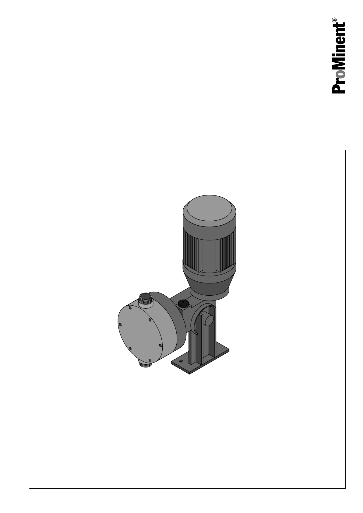
Operating Manual
P_PL_0001_SW
Plasma PSMa
Motorised Diaphragm Metering Pump
Two sets of operating instructions are required for the safe, correct and proper operation of the metering pumps: The
product-specific operating instructions and the
and Hydraulic Accessories".
Both sets of operating instructions are only valid when read together.
Please carefully read these operating instructions before use! · Do not discard!
The operator shall be liable for any damage caused by installation or operating errors!
Translation of Original operating instructions (2006/42/EC) Vers. 10/2009
"General Operating Instructions ProMinent® Motor-Driven Metering Pumps
Technical changes reserved.
Page 2

Heidelberg ProMinent Fluid Controls India Pvt. Ltd.
2/2 M.E.S. Road
Yeshwanthpur
India
Telephone: 080 - 2357 8872 / 73 / 74
Fax: 080 - 2357 3743 / 2347 7984
email: prominent@hpfcindia.com
Internet: www.prominentindia.com
BA PL 001, 1, en_GB
, Bangalore – 560 022
© 2009
2
Page 3
Supplementary information
Fig. 1: Please read carefully!
Supplemental directives
Please read the following supplementary information in its entirety!
This information will enable you to make better use of the operating
instructions.
The following are highlighted separately in the document:
n Enumerated lists
. Operating instructions
Information
This provides important information relating to the
correct operation of the unit or is intended to make your
work easier.
Safety information
Safety information is identified by pictograms - see Safety Chapter.
User information
State the identcode and serial number
Two sets of operating instructions are required for the safe, correct
and proper operation of the metering pumps: The product-specific
operating instructions and the "General Operating Instructions ProM‐
inent® Motor-Driven Metering Pumps and Hydraulic Accessories".
Both sets of operating instructions are only valid when read
together.
Please read these operating instructions carefully before use! Do not
discard!
Please state the identcode and the serial number that you find on the
specification label in all correspondence or when you order spare
parts. This enables us to clearly identify the unit type and material
version.
3
Page 4

Table of contents
Table of contents
1 Identcode ............................................................................. 5
2 About this Pump ................................................................... 6
3 Safety Chapter ..................................................................... 7
4 Storage, Transport and Unpacking .................................... 10
5 Overview of the Unit and Control Elements ....................... 12
6 Functional Description ....................................................... 13
6.1 Drive Unit ................................................................... 13
6.2 Liquid End .................................................................. 14
7 Assembly ........................................................................... 15
8
Installation .......................................................................... 16
8.1 Hydraulic Installation .................................................. 16
8.2 Electrical Installation .................................................. 16
9 Commissioning .................................................................. 18
10 Maintenance ...................................................................... 20
11 Repair ................................................................................ 22
11.1 Cleaning Valves ....................................................... 22
11.2 Replacing the Diaphragm ........................................ 24
12 Troubleshooting ................................................................. 26
13 Decommissioning ............................................................... 27
14 Technical Data ................................................................... 29
14.1 Performance Data .................................................... 29
14.2 Degree of Protection and Safety Requirements ...... 29
14.3 Ambient Conditions .................................................. 30
14.3.1 Temperatures ....................................................... 30
14.3.2 Climate .................................................................. 31
14.4 Gear Oil ................................................................... 31
14.5 Sound Pressure Level.............................................. 31
15 Appendix ............................................................................ 32
15.1 Dimensional Drawings ............................................. 32
15.2 Diagrams for Setting the Metering Capacity ............ 33
15.3 Ordering Information ................................................ 34
15.3.1 Spare Parts Sets ................................................... 34
15.3.2 Diaphragms .......................................................... 35
15.4 EC Declaration of Conformity .................................. 36
15.5 Decontamination Declaration ................................... 37
16 Index................................................................................... 38
4
Page 5
1 Identcode
Plasma Series, Version I
PSMa Type Power
bar l/h
05050 5 50
05065 5 65
05100 5 90
05120 5 120
05200 5 200
05260 5 260
Material of dosing head/valves
PC PVC with EPDM sealing material
PP Polypropylene with EPDM sealing material
Identcode
TT PTFE with PTFE sealing material
SS Stainless steel with PTFE sealing material
Dosing head design
0 Standard
Hydraulic connection
0 Standard connection - cap nut with hose
connection
1 Cap nut with stainless steel insert (standard
with stainless steel)
Motor connection
S 3-ph, 400 V ± 10 %, 50 Hz
(60 Hz versions on request)
1 without motor
Stroke sensor
0 no stroke sensor
Stroke length adjust‐
ment
0 manual
(standard)
5
Page 6

About this Pump
2 About this Pump
ProMinent
effective diaphragm metering pumps
®
Plasma PSMa motorised metering pumps are very
. They are compact, energysaving, provide excellent precision and reflect the high standards of
quality of ProMinent motorised metering pumps.
ProMinent
®
Plasma PSMa motorised metering pumps are available
up to metering outputs of 260 l/h. There are six different maximum
metering output levels available.
6
Page 7

3 Safety Chapter
Safety Chapter
Explanation of the safety information
Warning signs denoting different types
of hazard
The following signal words are used in these operating instructions
to identify different severities of a hazard
Signal word Meaning
WARNING Denotes a possibly hazardous
CAUTION Denotes a possibly hazardous
The following warning signs are used in this operating instructions to
denote different types of hazard:
Warning sign Type of hazard
:
situation. If this is disregarded
you are in a life-threatening
situation and this can result in
serious injuries.
situation.
could result in slight or minor
injuries or material damage.
Warning of a hazardous area
If this is disregarded, it
,
Correct and Proper Use
Safety information
Warning of hazardous electrical
voltage
n The pump may only be used to dose liquid feed chemicals
n The pump may only be used after it has been correctly installed
and commissioned in accordance with the technical data and
specifications contained in the operating instructions.
n Any other uses or modifications are prohibited.
n The pump is not intended to dose gaseous media or solids.
n The pump is not intended for operation in EX zones.
n The pumps is not intended to dose combustible fluids.
n The pump should only be operated by trained and authorised
personnel.
n You are obliged to observe the information contained in the oper‐
ating instructions at the different phases of the device''s service
life.
.
7
Page 8

Safety Chapter
Safety information
WARNING!
Warning of hazardous or unknown feed chemical
Should a hazardous or unknown feed chemical be
used, it may escape from the hydraulic components
when working on the pump
.
– Take appropriate protective measures before
working on the pump (protective eyewear, protective
gloves, ...). Read the safety data sheet on the feed
chemical.
– Drain and flush the liquid end before working on the
pump.
CAUTION!
Warning of feed chemical spraying around
Feed chemical can spray out of the hydraulic compo‐
nents if they are manipulated or opened due to pressure
in the liquid end and adjacent parts of the system.
– Depressurise the system prior to undertaking any
maintenance or repair work!
CAUTION!
Warning of feed chemical spraying around
An unsuitable feed chemical can damage the parts of
the pump contacted by the chemical
.
– Take into account the resistance of the material
contacted by the chemical when selecting the feed
chemical - refer to the ProMinent
®
resistance list
in the product equipment catalogue or at
www.prominent.com
.
CAUTION!
Danger of personal and material damage
The use of untested third party parts can result in
damage to personnel and material damage
.
– Only fit parts to dosing pumps, which have been
tested and recommended by ProMinent.
CAUTION!
Danger
from incorrectly operated or inadequately main‐
tained pumps
Danger can arise from a poorly accessible pump due to
incorrect operation and poor maintenance.
– Ensure that the pump is accessible at all times.
CAUTION!
Warning of illegal operation
Observe the regulations that apply where the unit is to
be installed
.
8
Page 9

Information in the event of an emer‐
gency
Safety Chapter
The pump cannot be de-energised!
In
the event of an electrical accident, disconnect the mains cable from
the mains or press the emergency cut-off switch fitted on the side of
the system!
Should feed chemical leak out, refer to the feed chemical's safety
data sheet. To switch off the pump in such an event, disconnect the
mains cable from the mains or press the emergency cut-off switch
fitted on the side of the system. If necessary depressurise the
hydraulic system around the pump.
Qualification of personnel
Activity Qualification
Storage, transport, unpacking Technical personnel
Installation, installation of
hydraulic system
Electrical Installation Electrician
Operation Instructed personnel
Maintenance, repair Technical personnel
Decommissioning, disposal Technical personnel
Troubleshooting Technical personnel, electri‐
Electrician
Electricians
on electrical systems and recognise and avoid possible hazards
independently based on his/her technical training and experience, as
well as knowledge of pertinent standards and regulations.
Electricians should be specifically trained for the working environ‐
ment in which the are employed and know the relevant standards
and regulations.
Electricians must comply with the provisions of the applicable statu‐
tory directives on accident prevention.
Instructed personnel
The instructed personnel have been instructed by the operator in a
training session about the tasks allocated to them and potential
hazards with incorrect and improper conduct.
Technical personnel
Technical personnel are deemed to be people, who are able to
complete the tasks allocated to them and recognise and avoid
hazards independently based on his/her technical training and expe‐
rience, as well as knowledge of pertinent regulations.
are deemed to be people, who are able to complete work
Technical personnel
cian, instructed personnel
Sound Pressure Level
9
The sound pressure level is < 70 dB (A)
at a maximum stroke length, maximum stroke rate, maximum
counter pressure (water) according to:
DIN EN 12639 (Noise testing on liquid pumps).
Page 10

Storage, Transport and Unpacking
4 Storage, Transport and Unpacking
Safety information
WARNING!
It is prohibited to ship pumps for radioactive media
They will also not be accepted by ProMinent!
WARNING!
Only return metering pumps for repair in a cleaned state
and with a flushed liquid end - refer to the chapter on
decommissioning! Should safety precautions neverthe‐
less be necessary, in spite of carefully cleaning the
pumps, the requisite information must be entered on the
Decontamination Declaration form.
The Decontamination Declaration form constitutes an
integral part of an inspection/repair order. A unit can only
be inspected or repaired if a Decontamination Declara‐
tion form has been completed correctly and in full by an
authorised and qualified person on behalf of the pump
operator.
The "Decontamination Declaration" form can be found
in the Appendix or at
www.prominent.com
!
.
Scope of delivery
CAUTION!
Danger of environmental and material damage
The unit can be damaged or oil may escape due to
incorrect or improper storage or transportation
– The unit should only be stored or transported in a
well packaged state - preferably in its original pack‐
aging.
– Only transport the unit with the locking screw - not
the bleed plug - fitted to the oil filling opening.
– The packaged unit should also only be stored or
transported in accordance with the stipulated
storage conditions.
– The packaged unit should be protected from mois‐
ture and the ingress of chemicals.
Compare the delivery note with the shipment:
n Metering pump
n Product-specific operating instructions with EC Declaration of
Conformity
n "General Operating Instructions ProMinent® Motor-Driven
Metering Pumps and Hydraulic Accessories".
!
Storage
Personnel:
1. Place the caps on the valves.
2. Preferably place the pump on a pallet
n
Technical personnel
.
10
Page 11

Storage, Transport and Unpacking
3. Cover
Store the pump in a dry, sealed place in the following ambient condi‐
tions.
the pump with a tarpaulin cover - allowing for rear venti‐
lation.
Ambient Conditions
Specification Value Unit
Minimum storage and transport
temperature
Maximum storage and transport
temperature
Maximum air humidity * 95 % rel.
* non-condensing
-10 °C
+50 °C
humidity
11
Page 12
1
3
4
P_PL_0002_SW
2
5
6
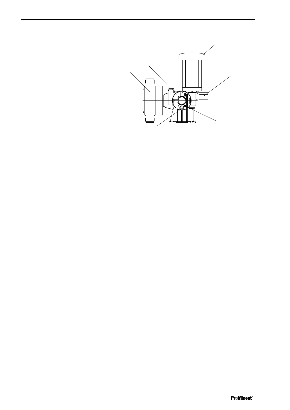
Overview of the Unit and Control Elements
5 Overview of the Unit and Control Elements
Fig. 2: Complete overview
1 Drive motor
2 Bleed plug / Locking plug
3 Liquid end
4 Oil drain screw
5 Drive unit
6 Stroke length adjustment knob
not shown Oil level indicator (on rear)
12
Page 13

6 Functional Description
1
2
3
6
4
5
7
P_PL_0003_SW
0
s s
a)
180 360 0
b)
180 360
ω ω
P_PL_0009_SW
6.1 Drive Unit
Functional Description
The metering pump is an oscillating displacement pump, the stroke
length of which can be adjusted
pump. A worm gear (2) reduces the drive rotation of the pump. An
eccentric cam (3) converts it together with the receiving fork (8) into
an oscillating movement of the driving rod (4). A return spring (5)
presses the receiving fork together with the driving rod in a force-fit
manner against the eccentric cam and thus triggers the return
stroke. The stroke length can be adjusted by the stroke adjustment
knob (6) and the shaft (7). The different stroke lengths are in effect
caused by the limitation of the return stroke (cf.
stroke movement ” on page 13
motion to the diaphragm.
. An electric motor (1) drives the
Ä “Illustration of the
). The driving rod transmits the stoke
Illustration of the stroke movement
Fig. 3: Cross-section through drive unit
1 Electric motor
2 Worm gear
3 Eccentric cam
4 Driving rod
5 Return spring
6 Stroke adjustment knob
7 Shaft
8 Receiving fork
Fig. 4: Stroke movement at a) maximum stroke length and b) reduced
stroke length.
s Stroke velocity
⍵ Angle of rotation of eccentric cam
+ Pressure stroke
- Suction stroke
13
Page 14

Functional Description
6.2 Liquid End
The diaphragm (3) hermetically closes the pump volume of the
dosing
soon as the diaphragm (3) is moved in the dosing head and the feed
chemical flows out of the dosing head through the discharge valve
(1). As soon as the diaphragm (3) is moved in a counter direction,
the discharge valve (1) closes due to the negative pressure in the
dosing head and fresh feed chemical flows through the suction valve
(4) into the dosing head. One cycle is thus completed.
head (2) towards the outside. The suction valve (4) closes as
Fig. 5: Cross-section through the liquid end
1 Discharge valve
2 Dosing head
3 Diaphragm
4 Suction valve
14
Page 15

7 Assembly
Assembly
CAUTION!
Maintenance to prevent personal and material damage
Also refer to the "General Operating Instructions ProM‐
inent® Motor-Driven Metering Pumps and Hydraulic
Accessories"!
CAUTION!
Danger of environmental and material damage
The unit can be damaged or oil may escape due to
incorrect or improper storage or transportation
– The unit should only be stored or transported in a
well packaged state - preferably in its original pack‐
aging.
– Only transport the unit with the locking screw - not
the bleed plug - fitted to the oil filling opening.
– The packaged unit should also only be stored or
transported in accordance with the stipulated
storage conditions.
– The packaged unit should be protected from mois‐
ture and the ingress of chemicals.
!
CAUTION!
Warning about personal and material damage
Personal
is operated outside of the permissible ambient condi‐
tions.
– Please observe the permissible ambient conditions
and material damage may be caused if the unit
- refer to the chapter entitled "Technical Data".
15
Page 16

Installation
8 Installation
8.1 Hydraulic Installation
WARNING!
Warning of feed chemical reactions to water
Feed chemicals that should not come into contact with
water may react to residual water in the liquid end that
may originate from works testing
– Blow the liquid end dry with compressed air through
the suction connector.
– Then flush the liquid end with a suitable medium
through the suction connector.
CAUTION!
Maintenance to prevent personal and material damage
Also refer to the "General Operating Instructions ProM‐
inent® Motor-Driven Metering Pumps and Hydraulic
Accessories"!
.
8.2 Electrical Installation
Personnel:
n
Technical personnel
WARNING!
Risk of electric shock
The
electrical installation of the unit may only be under‐
taken by technically trained personnel with a proven
qualification.
CAUTION!
Maintenance to prevent personal and material damage
Also refer to the "General Operating Instructions ProM‐
inent® Motor-Driven Metering Pumps and Hydraulic
Accessories"!
CAUTION!
The pump can be damaged
pump can be damaged if the motor drives the pump
The
in the wrong direction.
– When wiring the motor, pay due care and attention
to the correct direction of rotation indicated by the
arrow on the motor housing (cf. diagram below).
16
Page 17

P_SI_0012_SW
Fig. 6: Direction of rotation of motor
–
Key motor data can be found on the unit specification
label.
–
The terminal wiring diagram is located in the terminal
box.
–
The motor can only be wired in star (Y) configura‐
tion.
Installation
Personnel:
n
Electrician
17
Page 18

0
1
9
P_PL_0006_SW
Commissioning
9 Commissioning
Safety information
Fitting the bleed plug
CAUTION!
Maintenance to prevent personal and material damage
Also refer to the "General Operating Instructions ProM‐
inent® Motor-Driven Metering Pumps and Hydraulic
Accessories"!
CAUTION!
Possible environmental and material damage
The locking screw on the oil filling opening is factory
fitted and, during operation, prevents any pressure
compensation between the drive housing and the
surroundings. This ensures that oil can be pushed out of
the drive housing.
– Replace the locking screw on the oil filling opening
with the bleed plug supplied.
– Retain the locking screw for subsequent transporta‐
tion of the unit.
-
Checking the oil level
Checking the direction of rotation
Adjusting the stroke length
When the pump is idle, check whether the oil level in the pump is in
the middle of the oil level indicator
This will rule out the pump losing oil and suffering damage.
When commissioning the unit, check whether the drive motor is
rotating correctly - check this against the arrow on the motor housing
or the diagram in the chapter entitled "Electrical Installation."
CAUTION!
– Only adjust the stroke length when the pump is
running.
–
Only turn the stroke adjustment knob one revolu‐
tion, corresponding to 100% stroke length. The
figures on the stroke adjustment knob x 10 corre‐
spond to the stroke length set in % - see diagram
below.
.
Fig. 7: 1 revolution = 100 % stroke length
18
Page 19

Commissioning
Correctly adjusting the pump:
n Select as large a stroke length as possible for viscous feed
chemicals.
n Select as large a stroke length as possible for outgassing feed
chemicals.
n Select as high a stroke rate as possible for good mixing
n Do not set the stroke length at less than 30 % for precise
dosing.
.
Eliminating priming problems (only with TTT and SST)
Should you experience priming problems during
commissioning, unscrew the valves from the liquid
end, place on a solid surface and, using a brass bar
(2), gently tap with a hammer (1) the PTFE ball seat disc
through the valve ball - see diagram below. Then allow
the valves to prime in a damp state.
Fig. 8: Tapping the valve seat disc
1 Hammer, approx. 300 g
2 Brass bar Ø 9 x approx. 200 mm
19
Page 20

Maintenance
10 Maintenance
WARNING!
is mandatory that you read the safety information and
It
specifications in the "Storage, Transport and
Unpacking" chapter prior to shipping the pump.
CAUTION!
Warning of feed chemical spraying around
Feed chemical can spray out of the hydraulic compo‐
nents if they are manipulated or opened due to pressure
in the liquid end and adjacent parts of the system.
– Depressurise the system before commencing work
on hydraulic parts!
Standard liquid ends:
Interval Maintenance task Personnel
After approx.
ating hours
Quarterly* n Check that the dosing lines are fixed firmly to the liquid
Changing gear oil
5,000 oper‐
Change gear oil - refer to "Changing gear oil" in this chapter. Instructed
end.
n Check
n Check the tightness of the entire liquid end - particularly
around the leakage hole!
n Check that the flow is correct: allow the pump to prime
briefly.
n Check that the electrical connections are intact
n Check that the dosing head screws are tight
that the suction valve and discharge valve are tight.
* under normal loading (approx. 30 % of continuous operation)
Under heavy loading
Draining gear oil
1. Remove the bleed plug
2. Place an oil tray under the oil drain screw
3. Unscrew the oil drain screw
4. Allow the gear oil to run out of the drive
5. Replace the oil drain screw
(e.g. continuous operation): Shorter intervals.
(1).
(2) from the drive housing.
(2) with a new seal.
personnel
Technical
personnel
(2).
.
Filling gear oil
1. Start up the pump.
2. Slowly fill gear oil through the opening for the bleed plug
until the oil level indicator (3) is half-covered.
3. Allow the pump to run for a further 1... 2 minutes.
4. Replace the bleed plug
(1).
(1)
20
Page 21

Tightening torque
Maintenance
Specification Value Unit
Tightening torque for screws: 9.0 Nm
21
Page 22

Repair
11 Repair
Safety information
WARNING!
is mandatory that you read the safety information and
It
specifications in the "Storage, Transport and
Unpacking" chapter prior to shipping the pump.
WARNING!
Contact with the feed chemical
Parts that come into contact with the feed chemical
become uncovered and touched during repairs.
– Protect yourself from the feed chemical should it be
hazardous. Read the safety data sheet on the feed
chemical.
CAUTION!
Warning of feed chemical spraying around
Feed chemical can spray out of the hydraulic compo‐
nents
if they are manipulated or opened due to pressure
in the liquid end and adjacent parts of the system.
– Depressurise the system prior to undertaking any
maintenance or repair work!
11.1 Cleaning Valves
Repairing ball valves
Personnel:
CAUTION!
Warning about personal and material damage
Feed chemical may escape from the liquid end
example, if ball valves not repaired correctly.
– Only use new components that fit your valve - both
– Pay attention to the flow direction of the discharge
1. Screw on the valve cap (5) on the suction side
2. Carefully remove the parts from the valve body
3. Replace the worn parts
4. Clean the remaining parts
5. Check all parts.
6. Insert the valve ball (3) and the valve seat
7. Screw on the valve cap (5).
n
Technical personnel
in terms of shape and chemical resistance!
and suction connections when fitting the valve.
.
.
(4).
, for
- see diagram.
(2).
22
Page 23

1
2
3
4
5
P_SI_0013_SW
Fig. 9: Simple cross-section through ball valve
1 Flat seal
2 Valve body
3 Valve ball
4 Valve seat
5 Valve cap
Repair
23
Page 24

Repair
11.2 Replacing the Diaphragm
WARNING!
Depending on the design
feed chemical may have accumulated behind the
diaphragm in the backplate following a leak!
– Take this feed chemical into consideration when you
are planning a repair - especially if it is hazardous!
, a few cubic centimetres of
Personnel:
n If necessary take protective measures.
n Read the safety data sheet on the feed chemical.
n Depressurise the system.
1. Empty
the feed chemical to run out; flush out with a suitable
medium; flush the liquid end thoroughly when using hazardous
feed chemicals!
2. With
end position at 0 % stroke length (the drive shaft is then difficult
to turn).
3. Switch off the pump.
4. Unscrew the hydraulic connectors on the discharge and
suction side.
5. Remove the 6 screws on the dosing head
6. Remove the dosing head
7. Loosen
wards turn in a clockwise direction.
8. Unscrew the diaphragm fully from the drive shaft
9. Tentatively screw the new diaphragm anticlockwise onto the
drive shaft as far as its stop position.
ð
10. Should this not work, remove dirt or swarf out of the threads
and screw the diaphragm correctly onto the drive shaft this
time.
11. Place the dosing head with the screws onto the diaphragm
the suction connector must be pointing downwards when the
pump is installed later.
the liquid end: Turn the liquid end upside down and allow
the pump running, move the stroke adjustment knob to its
the diaphragm from the drive shaft with a gentle back‐
The diaphragm is now sitting at the end position of the
thread.
n
Technical personnel
.
.
.
-
12. Tighten the screws gently to start with.
13. Start up the pump and adjust the stroke length to 100
14. Now
further tighten the screws crosswise. See below for tight‐
ening torque.
CAUTION!
Warning of escaping feed chemical
The liquid end may leak should it not be possible to
check the tightening torque of the screws.
» see next page
%.
24
Page 25

Repair
– Check the tightening torque of the screws after 24-
hours of operation
– Recheck the tightening torque again after three
months with PP dosing heads!
!
Tightening torque
Specification Value Unit
Tightening torque for screws: 9.0 Nm
25
Page 26

Troubleshooting
12 Troubleshooting
Safety information
WARNING!
Warning of hazardous or unknown feed chemical
Should a hazardous or unknown feed chemical be
used, it may escape from the hydraulic components
when working on the pump
– Take appropriate protective measures before
working on the pump (protective eyewear, protective
gloves, ...). Read the safety data sheet on the feed
chemical.
– Drain and flush the liquid end before working on the
pump.
CAUTION!
Warning of feed chemical spraying around
Feed chemical can spray out of the hydraulic compo‐
nents if they are manipulated or opened due to pressure
in the liquid end and adjacent parts of the system.
– Depressurise the system prior to undertaking any
maintenance or repair work!
.
WARNING!
Danger of an electric shock
Personnel working on electrical parts can be electro‐
cuted
if all electrical lines carrying current have not been
disconnected.
– Disconnect the supply cable before working on the
motor and prevent it from being reconnected acci‐
dentally.
– Any separately driven fans, servo motors, speed
controllers or diaphragm rupture sensors fitted
should also be disconnected.
– Check that the supply cables are de-energised.
Tasks
Error description Cause Solution Personnel
Pump does not prime in spite of
full
stroke motion and bleeding.
Pump does not reach high pres‐
sure rates.
The valves are dirty or
worn.
The valves are dirty or
worn.
The motor is wired incor‐
rectly.
Repair the valves - see chapter
entitled "Repair".
Repair the valves - see chapter
entitled "Repair
1.
Check the mains voltage and
mains frequency.
2. Wire the motor correctly.
".
Technical
personnel
Technical
personnel
Electrician
The mains voltage has
failed.
The drive motor is very hot. The discharge line is seri‐
ously constricted.
Eliminate the cause. Electrician
Rectify any constriction of the
discharge line
.
Technical
personnel
26
Page 27

13 Decommissioning
Decommissioning
Decommissioning
WARNING!
Danger from chemical residues
is normally chemical residue in the liquid end and
There
on the housing after operation. This chemical residue
could be hazardous to individuals.
– It is mandatory that the safety information relating to
the "Storage, Transport and Unpackaging" chapter
is read before shipping or transporting the unit.
– Thoroughly clean the liquid end and the housing of
chemicals and dirt. Read the safety data sheet on
the feed chemical.
WARNING!
Warning of hazardous or unknown feed chemical
Should a hazardous or unknown feed chemical be
used, it may escape from the hydraulic components
when working on the pump.
– Take appropriate protective measures before
working on the pump (protective eyewear, protective
gloves, ...). Read the safety data sheet on the feed
chemical.
– Drain and flush the liquid end before working on the
pump.
Final decommissioning
CAUTION!
Warning of feed chemical spraying around
Feed chemical can spray out of the hydraulic compo‐
nents
if they are manipulated or opened due to pressure
in the liquid end and adjacent parts of the system.
– Depressurise the system prior to undertaking any
maintenance or repair work!
CAUTION!
Danger of damage to the unit
into account the information in the "Storage, Trans‐
Take
port and Unpackaging" chapter if the system is decom‐
missioned for a temporary period.
Personnel:
1. Disconnect the pump from the mains power supply
2. Empty the liquid end by turning the pump upside down and
allowing the feed chemical to run out
3. Flush the liquid end with a suitable medium
head thoroughly when using hazardous feed chemicals!
4. Drain
the gear oil - refer to the chapter entitled "Maintenance".
n
Technical personnel
.
.
; flush the dosing
Temporary decommissioning
27
Page 28

Decommissioning
Disposal
Additional work: refer to the chapter on "Storage, Transport and
Unpacking
Personnel:
".
n
Technical personnel
CAUTION!
Environmental hazard due to gear oil
The pump contains gear oil that can cause damage to
the environment.
– Drain the gear oil from the pump.
– Note
the pertinent regulations currently applicable in
your country!
28
Page 29

14 Technical Data
14.1 Performance Data
Plasma with 0.2 kW motor, 400 V, 50
Hz, 1440 rpm
Technical Data
Type Minimum flow rate at maximum back
pressure
bar l/h ml/stroke Strokes/
05050 5 50 8.0 105 2 1.5 1 1/4" - 20
05065 5 65 7.8 140 2 1.5 1 1/4" - 20
05090 5 90 14.3 105 2 1.5 1 1/4" - 20
05120 5 120 14.3 140 2 1.5 1 1/4" - 20
05200 5 200 31.8 105 4 1.5 1 1/4" - 20
05260 5 260 31.0 140 4 1.5 1 1/4" - 20
All figures apply to water at 20 °C.
The suction lift applies to a filled suction line and filled liquid end
when installed correctly.
Accuracy
Specification Value Unit
Reproducibility ± 2 % *
* - at constant conditions and min. 30 % stroke length
Maximum
stroke rate
min
Stroke
length
mm m WS G-DN
Suction lift Connector
size
-
Materials that come into contact with
the feed chemical
Material version Liquid end Suction/
Discharge
connector
PC PVC PVC EPDM PTFE EPDM
PP Polypropylene Polypropylene EPDM PTFE EPDM
TT PTFE with
carbon
SS Stainless steel
SS 316
Shipping weight
PTFE with
carbon
Stainless steel
SS 316
Material version Shipping weight in kg
PP, PC, TT 12.1
SS 14.5
Seals Valve balls Valve seats
PTFE Ceramics PTFE
PTFE Stainless steel
SS 316
PTFE
14.2 Degree of Protection and Safety Requirements
Degree of protection
Protection against contact and humidity:
IP
55 in accordance with IEC 529, EN 60529, DIN VDE 0470 Part 1
29
Page 30

Technical Data
Safety requirements
Degree of protection:
1 - Mains power connection with protective earth conductor
14.3
Ambient Conditions
14.3.1 Temperatures
Pump, compl.
PP liquid end
PC liquid end
Specification Value Unit
Storage and transport temperature -10 ... +50 °C
Ambient temperature in operation
(drive):
Specification Value Unit
Max. temperature long-term at max.
operating pressure
Max. temperature for 15 min at max. 2
bar
Minimum temperature -10 °C
Specification Value Unit
Max. temperature long-term at max.
operating pressure
Max. temperature for 15 min at max. 2
bar
-10 ... +45 °C
45 °C
70 °C
45 °C
60 °C
TT liquid end
SS liquid end
Minimum temperature -10 °C
Specification Value Unit
Max. temperature long-term at max.
operating pressure
Max. temperature for 15 min at max. 2
bar
Minimum temperature -10 °C
Specification Value Unit
Max. temperature long-term at max.
operating pressure
Max. temperature for 15 min at max. 2
bar
Minimum temperature -10 °C
45 °C
120 °C
45 °C
120 °C
30
Page 31

14.3.2 Climate
14.4 Gear Oil
Technical Data
Specification Value Unit
Maximum air humidity *: 95 % rel.
humidity
* non-condensing
14.5 Sound Pressure Level
Sound Pressure Level
Manufacturer Name Viscosity class
(ISO 3442)
Shell Omala HD 320 0.25 l
The sound pressure level is < 70 dB (A)
at a maximum stroke length, maximum stroke rate, maximum
counter pressure (water
DIN EN 12639 (Noise testing on liquid pumps).
) according to:
Oil volume
31
Page 32

410
45
138
310
222
95
218
1 1/4" BSP
56
110
198
126
80
61
130
Ø 9
Ø25
3/4" BSP
Ø25
230
45
138
310
222
95
218
1 1/4" BSP
56
110
183
110
80
61
90 x 63
Ø 9
P_PL_0008_SW
Appendix
15 Appendix
15.1 Dimensional Drawings
Dimensional drawing of Plasma
Fig. 10: Dimensional drawing of Plasma PSMa - dimensions in mm
Dimensional drawing of Plasma
without motor
Fig. 11: Dimensional drawing of Plasma PSMa without motor - dimensions in mm
32
Page 33

15.2 Diagrams for Setting the Metering Capacity
10 20 30 40 50 60 70 80 90 100
10
20
30
40
50
60
70
1 2 3 4 5
50
60
70
80
90
100
10 20 30 40 50 60 70 80 90 100
10
20
30
40
50
60
70
80
90
100
1 2 3 4 5
100
110
120
130
140
150
110
120
10 20 30 40 50 60 70 80 90 100
5
10
15
20
25
30
35
40
45
50
s [%]
s [%]
s [%]
s [%]
C [l/h] PSMa 05050
C [l/h]
C [l/h]
C [l/h]
C [l/h]
C [l/h] PSMa 05065
C [l/h] PSMa 05090
C [l/h] PSMa 05120
1 2 3 4 5
50
55
60
65
70
p [bar]
p [bar]
p [bar]
p [bar]
55
10 20 30 40 50 60 70 80 90 100
10
20
30
40
50
60
70
80
90
100
1 2 3 4 5
80
90
100
110
B
A
B
A
B
A
B
A
Appendix
Fig. 12: A) Metering capacity C at medium back pressure according to the stroke length for maximum stroke
rate. B) Metering capacity C at medium back pressure according to the back pressure p.
33
Page 34

10 20 30 40 50 60 70 80 90 100
20
40
60
80
100
120
140
160
180
200
1 2 3 4 5
260
270
280
290
300
220
240
260
10 20 30 40 50 60 70 80 90 100
20
40
60
80
100
120
140
160
180
200
1 2 3 4 5
180
200
220
s [%]
C [l/ h] PSMa 05200
C [l/ h]
p [bar]
B
A
s [%]
C [l/ h] PSMa 05260
C [l/ h]
p [bar]
B
A
Appendix
Fig. 13: A) Metering capacity C at medium back pressure according to the stroke length for maximum stroke
rate. B) Metering capacity C at medium back pressure according to the back pressure p.
15.3 Ordering Information
15.3.1 Spare Parts Sets
Spare parts sets normally include the wearing parts of a liquid end.
Standard delivery for material version PPE
1 - Diaphragm
1 - Suction valve
1 - Discharge valve
2 - Valve balls
1 - Seal set
Standard delivery for material version SST
Spare parts sets for types 05050,
05065
1 - Diaphragm
2 - Valve balls
1 - Seal set
Liquid end Material version Part no.
FM 130 - DN 20 PP PMIN-3303001
FM 130 - DN 20 PC PMIN-3303002
FM 130 - DN 20 SS PMIN-3303003
FM 130 - DN 20 TT PMIN-3303004
34
Page 35

Spare parts sets for types 05100,
05120, 05200
, 05260
Appendix
Liquid end Material version Part no.
FM 260 - DN 20 PP PMIN-3303005
FM 260 - DN 20 PC PMIN-3303006
FM 260 - DN 20 SS PMIN-3303007
FM 260 - DN 20 TT PMIN-3303008
PMIN = Heidelberg ProMinent Fluid Controls India Pvt. Ltd.
15.3.2
Diaphragms for types 05050, 05065
Diaphragms for types 05100, 05120,
05200, 05260
Diaphragms
Liquid end Part no.
FM 130 PMIN-3301019
Liquid end Part no.
FM 260 PMIN-3301020
PMIN = Heidelberg ProMinent Fluid Controls India Pvt. Ltd.
35
Page 36

Appendix
15.4 EC Declaration of Conformity
Fig. 14
36
Page 37

15.5 Decontamination Declaration
Declaration of Decontamination
(see download: www.prominent.com)
Because of legal regulations and for the safety of our employees and operation equipment, we need the „declaration of decontamination”, with your signature, before your order can be handled.
Please make absolutely sure to include it with the shipping documents, or – even better – attach it to the
outside of the packaging.
Please return your products to:
ProMinent Dosiertechnik GmbH
Department: Reparaturabteilung
Im Schuhmachergewann 5-11
69123 Heidelberg, Germany
Please direct your inquiry to:
0049 6221 8420
customercare@prominent.de
Type of instrument / sensor: _________________________ Serial number: __________________________
Process data: Temperature: ___________________ [° C] Pressure: _________________ [bar]
Mediums and warnings:
Medium/
Concentration
Identi
-
fication
flammable
toxic
corrosive
harmful
/
irritant
other*harmless
Process
medium
Medium
for pro-
cess-
cleaning
Returned
part
cleaned
with
* explosive; oxidising; dangerous for the environment; biological risk; radioactive
Please tick should one of the above be applicable, include security sheet and, if necessary, special handling instructions.
Reason for return:
________________________________________________________________________________
________________________________________________________________________________
________________________________________________________________________________
Company data:
Company: ______________________ Phone number: ______________________
Contact person: ______________________ Fax: ______________________
Straße: ______________________ E-Mail: ______________________
Address: ______________________ Your order No: ______________________
„We hereby certify that the returned parts have been carefully cleaned. To the best of our knowledge they
are free from any residues in dangerous quantities.”
_________________________ _________________________________________________
Place, date Company stamp and legally binding signature
Appendix
Fig. 15
37
Page 38

Index
16 Index
A
About this Pump .................................................... 6
Accuracy ............................................................. 29
Air humidity ......................................................... 31
Ambient Conditions ............................................. 30
Appendix ............................................................. 32
Assembly .............................................................
B
Bleed plug ........................................................... 12
C
Capacity diagrams .............................................. 33
Cleaning Valves .................................................. 22
Climate ................................................................ 31
Commissioning .................................................... 18
Connector size .................................................... 29
Control Elements ................................................. 12
Correct and Proper Use......................................... 7
D
Declaration of Conformity .................................... 36
Decommissioning ................................................ 27
Decontamination Declaration .............................. 37
Degree of protection ............................................ 29
Diagrams ............................................................. 33
Diaphragm ........................................................... 14
Diaphragms ......................................................... 35
Dimensional Drawings ........................................ 32
Direction of rotation of ......................................... 17
Discharge valve ................................................... 14
Disposal .............................................................. 28
Dosing head ........................................................ 14
Drive Unit ............................................................ 13
E
EC Declaration of Conformity .............................. 36
Emergency ............................................................ 9
Emptying the liquid end ....................................... 27
Explanation of the safety information .................... 7
F
Flow rate ............................................................. 29
Functional Description ......................................... 13
G
Gear Oil ............................................................... 31
I
Identcode .............................................................. 5
Information in the event of an emergency ............. 9
Installation ........................................................... 16
IP ......................................................................... 29
15
L
Leakage hole ....................................................... 20
Liquid end ............................................................ 12
Liquid End ........................................................... 14
Locking screw ..................................................... 12
M
Maintenance ........................................................ 20
Materials that come into contact with the feed
chemical .............................................................. 29
motor ................................................................... 17
O
Oil drain screw .................................................... 12
Ordering Information ........................................... 34
Overview of the Unit ............................................ 12
P
Protection against contact and humidity ............. 29
Q
Qualification of personnel....................................... 9
R
Radioactive ......................................................... 10
Repair .................................................................. 22
Replacing the Diaphragm .................................... 24
S
Safety Chapter ...................................................... 7
Safety Declaration Form ..................................... 10
Safety requirements ............................................ 29
Scope of delivery ................................................. 10
Shipping weight ................................................... 29
Sound Pressure Level...................................... 9, 31
Spare Parts Sets ................................................. 34
Storage ................................................................ 10
Storage and transport temperature ..................... 30
Stroke length ....................................................... 18
Stroke length adjustment knob ........................... 12
Suction lift ............................................................ 29
Suction valve ....................................................... 14
T
Temperatures ...................................................... 30
Transport ............................................................. 10
Troubleshooting .................................................. 26
U
Unpacking ........................................................... 10
W
Warning sign.......................................................... 7
Weight ................................................................. 29
38
 Loading...