

Page 1
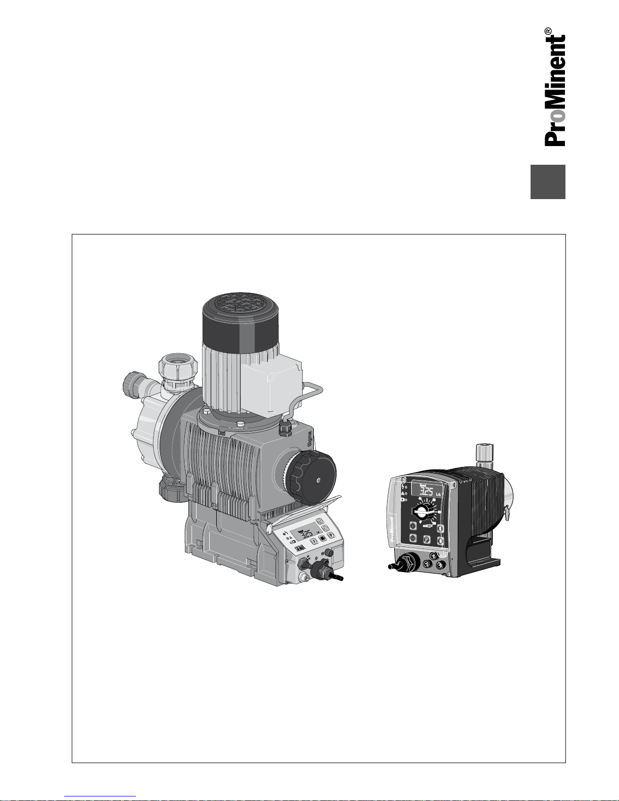
gamma/ L and Sigma with PROFIBUS
®
Function blocks
Installation and configuration manual
B0288
PROFIBUS
®
Parts no. 985968 BA G 032 04/11 EN
Please carefully read these operating instructions before use! · Do not discard!
The operator shall be liable for any damage caused by installation or operating errors!
Technical changes reserved.
Page 2

BA Gala Profi FB, 1, en_GB
© 2011
ProMinent Dosiertechnik GmbH
Im Schuhmachergewann 5-11
69123 Heidelberg
Germany
Telephone: +49 6221 842-0
Fax: +49 6221 842-617
email: info@prominent.com
Internet: www.prominent.com
2
Page 3

Table of contents
1 Installation of the GSD file in Step 7 Manager................................. 4
1.1 Creating a project.................................................................... 4
1.2
Install GSD file........................................................................ 7
2 Integrating the device and the function block into your own
project............................................................................................ 11
2.1
Add PROFIBUS® Master System.......................................... 11
2.2
Connecting the device to the PROFIBUS® Master System.. 14
2.3 Copying and linking a function block..................................... 17
3 Function blocks for gamma/L and Sigmas.................................... 28
3.1 Introductory information........................................................ 28
3.2 Function block FB110 for basic functionality......................... 30
3.3 Function block FB111 for complete functionality................... 34
3.3.1 Explanations of the operating modes................................. 34
3.3.2 Tables for the addresses.................................................... 38
Table of contents
3
Page 4

1 Installation of the GSD file in Step 7 Manager
This installation manual is only for persons who are familiar
with the Siemens Simatic S7 PLC.
Prerequisites:
The installation package (such as “Delta_S7_function_block” or Gamma‐
Sigma_S7_function_block”), with the GSD file (such as prom0B02.gsd”)
must have been downloaded from the
www.prominent.com
website. (The
installation package for the respective product is there.)
The installation package must be open on the PC and the GSD must be
copied from the installation package into a folder.
1.1 Creating a project
Installation of the GSD file in Step 7 Manager
4
Page 5

1.
Follow the path
“File è ‘New Project’ Wizard...”
and click with the
mouse.
ð
The
“Introduction”
window will be displayed:
2. Click the
[Next>]
button.
ð
The window
“Which CPU are you using in your project?”
will be
displayed:
Installation of the GSD file in Step 7 Manager
5
Page 6

3. Select the correct CPU.
When selecting the correct CPU the software version
that is imprinted on the CPU and the order number
help.
Click the
[Next>]
button.
ð
The window
“Which blocks do you want to add?”
will be dis‐
played:
4. Always place a check mark for option block OB1.
5. If the function will be called in selectable time intervals, in addition
select OB35 with a check mark (the operation blocks can vary
depending on CPU).
A more precise description of the performance scope
of the CPU is in your operating manual.
Installation of the GSD file in Step 7 Manager
6
Page 7

6. Click the
[Next>]
button.
ð
The window
“What do you want to call your project?”
will be
displayed:
7. After a project name has been entered (in this case “Pro‐
fibus_Delta”), click the
[Finish]
button.
ð
The Simatic Manager window will open - see the following
chapter.
1.2 Install GSD file
Fig. 1: Simatic Manager with main window with navigation bar
Installation of the GSD file in Step 7 Manager
7
Page 8

1. In Simatic Manager, in the navigation bar (left) select
“Simatic 300
Station”
.
ð
In the main window a symbol
“Hardware”
is displayed.
2. Double click the
“Hardware”
symbol.
ð
The Hardware Configurator will open:
Fig. 2: The Hardware Configurator
3.
Follow the path
“Options è Install GSD File”
and click with the
mouse.
ð
The
“Install GSD File”
window will open:
4. Use the
[Browse]
button to select the folder into which you have
copied the GSD file. (In this screenshot the folder "Profibus Delta" is
on drive "E:").
Installation of the GSD file in Step 7 Manager
8
Page 9

5. If the path was correct, the GSD file will be displayed in the window.
In this screenshot, this is the file “PROM0B02.gsd” for the delta (for
gamma/ L or Sigma it would be the file “PROM0596.gsd”).
6. Select the file and press the
[Install]
button.
ð
A warning will be displayed stating that the action cannot be
undone:
7. Click
[Yes]
.
ð
If this GSD file is already present, the following message will be
displayed:
Installation of the GSD file in Step 7 Manager
9
Page 10

8. Click
[Yes]
to install the GSD file.
ð
The following message will be displayed:
9. Click
[OK]
to conclude the installation.
10. Click
[Close]
to close the window.
The next chapter shows how you can integrate the ProMinent device
(pump, measuring transducer, etc.) into your own project.
Installation of the GSD file in Step 7 Manager
10
Page 11

2 Integrating the device and the function block into your own
project
Note: This description cannot go into all the details of PRO‐
FIBUS® communication.
If necessary attend an appropriate training course.
2.1
Add PROFIBUS® Master System
This section describes how to add a PROFIBUS® Master System into your
own project and how to generate a PROFIBUS® subnet:
1. Double click to open your own project (shown here with a red
border) that you created in chapter 1.1:
Fig. 3
2. Double click the
“Hardware”
symbol to open the Hardware Configu‐
rator:
Fig. 4
Integrating the device and the function block into your own project
11
Page 12

3. Add a Master System for the CPU: For example, for CPU
314C-2DP, right click slot X2 “DP”.
ð
The context menu will open:
Fig. 5
4. Here select
“Add Master System”
.
ð
The window
“PROFIBUS Interface DP”
will be displayed:
Fig. 6
5.
In the
“Parameters”
tab under
“Address”
enter the PROFIBUS
®
address of the CPU used.
Integrating the device and the function block into your own project
12
Page 13

6. Click
[New]
.
ð
The
“New Subnet PROFIBUS”
will be displayed:
Fig. 7
7. Under
“Name”
enter a name for the subnet of the PROFIBUS and
click
[OK]
.
ð
The window
“PROFIBUS Interface DP”
will be displayed again:
Fig. 8
8.
(If necessary via
“Properties”
special PROFIBUS® parameters can
be adjusted.)
Integrating the device and the function block into your own project
13
Page 14

9.
Mark the PROFIBUS® subnet and click
[OK]
.
ð
The Hardware Configurator connects the CPU (the Master
System) with the Subnet of the PROFIBUS®, which the Hard‐
ware Configurator now displays in this manner:
Fig. 9: Graphic presentation: Connection CPU (Master System) with the subnet of the PROFIBUS® in the Hardware Con‐
figurator (excerpt)
2.2
Connecting the device to the PROFIBUS® Master System
As soon as the PROFIBUS® master system has been added to the project
and the PROFIBUS® subnet is created, the gamma/ L or Sigma metering
pump can be connected to the PROFIBUS®:
1.
Call the catalog via
“Options è Display Catalog”
.
ð
To the right in the window you will see:
Fig. 10
Integrating the device and the function block into your own project
14
Page 15

2. Select the file
“gamma/ L”
under
“Profibus-DP
è
Additional Field Devices è General”
.
If the entry is not present, the GSD file is not correctly
installed.
3. Drag the
“gamma/ L”
file with the mouse to the Master System -
see the orange arrow in the screenshot below.
ð
A small "+” will appear as soon as the cursor is on “Your name
PROFIBUS DP Master System”.
Fig. 11
4. As soon as the mouse button is released a pop-up window will be
displayed - see illustration above.
Integrating the device and the function block into your own project
15
Page 16

5.
Under
“Address”
set the PROFIBUS® that is set on your gamma/ L
or Sigma - see supplemental instructions delta with PROFIBUS® and click
[OK]
.
If this address is not displayed (already allocated),
enter a new address. Then enter this address on your
actual gamma/ L or Sigma, as well.
ð
The Hardware Configurator will then connect the gamma/ L or
Sigma to the PROFIBUS® Master System (red box, right) via
the subnet, which the Hardware Configurator displays in this
manner:
Fig. 12: Connection of the Master System to the delta via the subnet (graphic presentation in the Hardware Configurator)
In the lower window area (red box) the individual slots and their
I-addresses and O-addresses (input addresses and output
addresses) of the gamma/L or Sigma are displayed.
6. If necessary, adjust the I-address ranges and O-address ranges. To
do this double click on the appropriate row.
ð
A window will open.
7. Here, enter the desired, changed address range and click
[OK]
.
The Hardware Configurator will supplement the
address range automatically.
The Hardware Configurator prevents the address from
being allocated twice. It handles I-addresses and Oaddresses separately.
8.
Save the addresses via the special diskette symbol with “0110” in
the toolbar.
Integrating the device and the function block into your own project
16
Page 17

9. Close the Hardware Configurator.
2.3 Copying and linking a function block
The supplied function blocks are embedded in the ProMinent
sample project “Gammadp.zip”; this is the only way that they
can be transported.
The principle steps:
1 - Download the zipped installation package (such as “Gamma‐
Sigma_S7_Funktionsblock.zip”) from the website (prerequisite).
2 - Drag the ProMinent sample project “Gammadp.zip” out of the installa‐
tion package (prerequisite).
3 - Create a function in your own project (here FC1).
4 - Save the zipped ProMinent sample project “Gammadp.zip” in the
Simatic Manager and open it - in this process it will simultaneously be
unzipped - retrieved.
5 - Copy the function block or the function blocks from this location into
your own project.
6 - Link the required function blocks into your own function (in this case
FC1).
7 - Generate a data block.
8 - Enter the addresses in the function block.
9 - Enter the function parameters in the function block.
Integrating the device and the function block into your own project
17
Page 18

1. In the Simatic Manager in the Navigation window, on the left, select
“Blocks” and highlight it.
Fig. 13
2.
Follow the path
“Insert è S7 Block è 3 Function”
and click with the
mouse.
ð
The window
“Properties - Function”
will open
Fig. 14
3. To create the function, here enter a
“name”
(e.g. FC1) and a
“symbolic name”
and under
“Symbol Comment”
enter its meaning.
Then click
[OK]
.
ð
In the main window the new function (e.g. FC1) will additionally
be displayed.
Integrating the device and the function block into your own project
18
Page 19

Fig. 15
1.
Follow the path
“File è Retrieve ...”
and click with the mouse.
ð
The window
“Retrieving - Select an archive”
will be displayed:
Fig. 16
Archive = ZIP file
Archive = pack (zip)
Retrieve = unpack (unzip)
Integrating the device and the function block into your own project
19
Page 20

2. Here select your folder with the packed ProMinent sample project
“Gammadp”, and click
[Open]
.
ð
The window
“Select destination directory”
will be displayed.
Fig. 17
3. Here select the directory into which the ProMinent sample project
will be unzipped, and click
[OK]
.
ð
First a DOS Window (with black background) will be displayed,
in which the ProMinent sample project will be unzipped. Then
“Retrieve”
window will be displayed:
Fig. 18
Integrating the device and the function block into your own project
20
Page 21

4. To unpack Click
[Yes]
.
ð
The SIMATIC Manager now displays the unpacked project:
Fig. 19
In this project you will find the 2 standard function
blocks FB110 and FB111 (FB110 for the basic
version or FB111 for the complete version).
Integrating the device and the function block into your own project
21
Page 22

Fig. 20
5.
Select the desired function block and copy it via
“Edit è Copy”
, for
example.
Fig. 21
6. Select your own project in the
“Window”
menu.
Integrating the device and the function block into your own project
22
Page 23

Fig. 22
7. Copy the desired function block into your own project via the
“Edit
è
Paste”
.
Integrating the device and the function block into your own project
23
Page 24

Fig. 23
8. To link the function block into your own function, open the function
by clicking it (here, FC1).
ð
The following window will be displayed:
Fig. 24
Integrating the device and the function block into your own project
24
Page 25

9. Now drag the function block (here FB110) out of the function block
catalog, left, with the mouse into the network shown above - see the
orange arrow in the screen shot above.
ð
In the window with the networks, a depiction of the function
block is displayed:
Fig. 25
Integrating the device and the function block into your own project
25
Page 26

Each function block needs a data block to save its data
(DB ...).
For better understandability use the same number that is
used for the function block when naming the data block.
10. Click the red
“???”
and assign a name for the data block of this
function block (e.g. “DB110”).
In this process the data block will be generated auto‐
matically in the background.
Fig. 26
ð
Now function block FB110 has the data block DB110 - see 1st
red box.
Integrating the device and the function block into your own project
26
Page 27

11. Now the complete addresses must still be entered on the input of
the function block - see 2nd red box. Then go back to the Hardware
Configurator (e.g. via the task bar on the lower edge):
Fig. 27
ð
The green lines that in the screenshot show the relationship
between the input addresses (
“I_Adr_...”
-->
“I-address)”
). The
red arrows show the relationship between the output addresses
(
“O_Adr_...”
-->
“O-address)”
).
12. In the function block, click in front of the selected address name (left
in Fig. 27, bordered).
13. See the table “Relationship: Address names - slots of the function
block” for the associated slot of the appropriate function block, in
chapter 3.
14. In the Hardware Configurator, find the start address of the appro‐
priate address range for this slot.
15. Enter the start address in the function block and press the
[ENTER]
key.
16. Perform this step for all
“I_Adr_...”
and
“O_Adr_...”
.
17. To specify the remaining parameters, use your own operating con‐
cept for this pump and refer to the tables in chapter 3.
Integrating the device and the function block into your own project
27
Page 28

3 Function blocks for gamma/L and Sigmas
3.1 Introductory information
In the sample project there are 2 variants of function blocks:
1 -
FB110 for basic functionality
2 - FB111 for complete functionality
1 FB110 for basic functionality contains the functions:
n Start/Stop
n Setpoint 0-100%
n Warning/fault message (group bit)
n Simple PROFIBUS® monitoring
2 FB111 for complete functionality contains the functions:
n Start/Stop
n Selection of setpoint specification/lot
n Batch handling
n Contact activation with specification of a factor
n Setpoint 0-100%
n Stroke counter
n Quantity counter
n Concentration output (option)
n Warning/fault message (group bit)
n Detail specification of the warning
n Detail specification of the fault message
n Simple PROFIBUS® monitoring
In the hardware address "I_ADR_Name" and "O_ADR_Name” mean ...
I_ Input
O_ Output
ADR_ Address
Name Name
.
In the interface names “abName” means ...
a (variants)
i Input
o Output
stat Statistical range of the function
block
b (variants)
Variant Type Value range
x Bool false, true
y Byte 0 ... 255 16#00... 16#FF
i Int 0 ... 65535 -32768 ... 32767
Functions of the function blocks
Explanation of the names in the standard
function blocks
Function blocks for gamma/L and Sigmas
28
Page 29

Variant Type Value range
d DInt 0 ...
4294967295
−2147483648 ...
2147483647
r Real -3.402822E
+38 ...
-1.175495E-38
1.175495E-38 ...
3.402822E+38
Name
Name
Function blocks for gamma/L and Sigmas
29
Page 30

3.2 Function block FB110 for basic functionality
Fig. 28
Address Type Slot
I_Adr_Status Int 10
I_Adr_Frequency Int 14
I_Adr_Max_Frequency Int 19
I_Adr_VpS Int 21
Appearance of the function block FB110
for basic functionality
Address name of the function block - slots
of the function block
Function blocks for gamma/L and Sigmas
30
Page 31

Address Type Slot
O_Adr_Control Int 1
O_Adr_Reset Int 5
O_Adr_Operation_Mode Int 7
O_Adr_Frequency Int 9
The input addresses or output addresses of gamma/ L or Sigma for the
CPU can be read out in the Hardware Configurator under gamma/ L or
Sigma for the appropriate slots:
Fig. 29
A more detailed explanation of the functions that are
assigned to the slots is provided in the “Supplemental
manual for gamma/ L and Sigma versions with PROFIBUS®”.
Relationship: Slots - address ranges of the
function block
Function blocks for gamma/L and Sigmas
31
Page 32

Interfaces Type Description
ixStart_Stop Bool If a 1 is applied on this input and if there is no fault, the
pump will be activated.
If the pump does not run or is not at a standstill the fol‐
lowing causes are possible:
n PROFIBUS® is faulty
n Pump is not in PROFIBUS® mode
n PROFIBUS® address is not correct
n Configuration is not correct
n Pump is manually set to stop
n Setpoint is on 0% (irSetpoint_0_100)
n ixFault_Lock = 1 and oxError = 1 or oxProfibus = 1
n Use Profibus Workaround
Adapt iiCycle_Error
ixReset Bool Resets the bit messages oxWarning, oxError and oxEr‐
rorProfibus. Resets the pump (positive flank sent).
ixFault_Lock Bool If 0, then the pump does not include a locking mechanism
for stored faults.
Logical link:
Start pump = ixStart_Stop
i.e. because the faults oxError and oxErrorProfibus
require acknowledgment, the pump automatically starts
up again if there is a fault on both sides.
If 1, then the pump does not include a locking mechanism
via fault messages oxError or oxErrorProfibus.
Logical link:
Start pump = ixStart_Stop & oxError = 0 & oxErrorPro‐
fibus = 0
i.e because the faults oxError and oxErrorProfibus
require acknowledgment, the pump does not automati‐
cally start up again if there is a fault on both sides.
irSetpoint_0_100 Real Entry of the setpoint of the metering pump in %.
The formula of the calculation is:
Set frequency = MaxFrequency * irSetpoint / 100
Through the real number the speed on the stroke can be
precisely selected, because the entry of 49.99%, for
example, is possible.
Likewise a direct connection of the integrated S7 con‐
troller is possible. For this the output parameter LMN
must be connected on this input.
Interfaces of the function block
Function blocks for gamma/L and Sigmas
32
Page 33

Interfaces Type Description
iiCycle_Error Int Specification of the cycles as delay of the warning and
fault oxWarning, oxError and oxErrorProfibus.
Through the delay short drop-outs in the PROFIBUS
®
system can be bridged.
The delay time is calculated as follows:
When using the function block in OB1:
Delay = measured cycle time * iiCycle_Error
When using the function block in OB35:
Delay = time wake alarm * iiCycle_Errror
This value uses the workaround Profibusbug.
If the pump is not at a standstill, or if it does not start up
on its own after a Profibus fault, adjust the value so that a
value of approx. 1s is achieved.
Example:
Call block of pump P1 every 50 ms, then the value 20
should be set.
oxRunning Bool 0 = pump is at standstill
1 = pump is running
oxWarning Bool 0 = No warning
1 = Warning active
oxError Bool 0 = no fault
1 = fault active
oxErrorProfibus Bool 0 = Profibus OK
1 = Profibus faulty
oyMode Byte 00 = Manual
01 = Batch
02 = Contact
03 = Analogue
orActualFrequency Real Actual stroke frequency in strokes/min
orActualDosingVolume Real For calibrated pump: Actual metering quantity in l or gal‐
lons
For uncalibrated pump: Value 0
Fig. 30
Statistical range of the instance block and
flag
Function blocks for gamma/L and Sigmas
33
Page 34

Variable Type Description
stat_Max_Freq Real Get maximum frequency via profibus of the pump. Con‐
version of the number into the real format
Status.Error Bool Errors are present.
Status.Warnings Bool Warnings are present.
Status.Intake Bool Pump is in intake operation (higher-level function - see
metering pump operating manual)
Status.Auxiliary Bool Pump is in auxiliary mode (higher-level function)
Status.Pause Bool Pump is switched to pause (higher-level function)
Status.Stop Bool Pump is stopped
Status.Flow Bool 1 = Metering monitor present
Status.FlowActive Bool 1 = Metering monitor activated
Status.FactorDivider Bool 1 =1/100, 0=1/1
Status.BatchMemory Bool 1 = Batch memory is activated
Status.Unit Bool 1 = Gallons, 0 = Litres
Status.Calibrated Bool 1 = Pump is calibrated
Status.PBWD Bool 1 (always)
Flag name Type Description
iiCycleWarning Int Flag - for how many cycle has the warning already been
queued. If this counter is > iiCycle_Error, then oxWarning
will be set
iiCycleFault Int Flag - for how many cycle has the fault has already been
queued. If this counter is > iiCycle_Error, then oxError will
be set
iiCycleFaultPB Int Flag - for how many cycle has the fault Profibus already
been queued. If this counter is > iiCycle_Error, then oxEr‐
rorProfibus will be set
iiWorkaround Int Internal use for workaround
iiWorkaround2 Int Internal use for workaround
3.3 Function block FB111 for complete functionality
3.3.1 Explanations of the operating modes
An the input
“iyMode”
, these operating modes can be selected:
00 - Manual
01 - Batch
02 - Contact
03 - Analog
3.3.1.1 Manual mode
In
“manual”
mode the follow signals are relevant:
Description of the variables of the function
block (statistical range)
Flags of the function block
Function blocks for gamma/L and Sigmas
34
Page 35

n ixStart_Stop
n irSetpoint0_100
n ixFault_Lock
n oxError
n oxErrorProfibus
The pumps starts, if:
ixStartStop = 1 & (ixFault_Lock = 0 or (ixFault_Lock = 1 & oxError = 0 &
oxErrorProfibus = 0)
with metering speed (strokes / h)
Maximum frequency * irSetpoint0_100 / 100
The pump does not start up, if:
ixStartStop = 0
3.3.1.2
Mode type batch
In
“Charge”
mode the following signals are relevant:
n ixStart_Stop
n ixStartBatch_Or_Contact
n ixBatchContactMemory
n irSetpoint0_100
n idStrokesInBatch
n ixFault_Lock
n oxError
n oxErrorProfibus
n odActualStrokesInBatch
n odRemainStrokesInBatch
Without memory function: ixBatchContactMemory = 0
With the input
“ixStart_Stop”
the pump can be switched off at any time.
Recommendation for operation:
“Set ixStart_Stop”
on 1 and only on 0 if
needed.
The input
“irSetpoint0_100”
specifies the metering speed.
Locking mechanism = manual mode
“ixStartStop”
= 1 & (
“ixFault_Lock”
= 0 or (
“ixFault_Lock”
= 1 &
“oxError”
= 0 &
“oxErrorProfibus”
= 0)
Metering speed (strokes / h) =
Maximum frequency *
“irSetpoint0_100”
/ 100
The pump does not start up, if:
“ixStartStop”
= 0
The pumps starts, at:
Positive flank on input
“ixStartBatch_Or_Contact”
.
Remaining strokes will be set to the value
“idStrokesInBatch”
(
“odRemainStrokesInBatch”
=
“idStrokesInBatch”
). The metering pump
runs until the remaining strokes counter is on 0.
A renewed flank on
“ixStartBatch_Or_Contact”
resets the value of the
remaining strokes to
“idStrokesInBatch”
. If the flank occurs during the
batch, the value will be limited to only idStrokesInBatch.
With memory function: ixBatchContactMemory = 1
Same as “Without memory function: ixBatchContactMemory = 0, but ...
The pumps starts, at:
Function blocks for gamma/L and Sigmas
35
Page 36

Positive flank on input
“ixStartBatch_Or_Contact”
.
Remaining strokes will be set to the value
“idStrokesInBatch”
(
“odRemainStrokesInBatch”
=
“idStrokesInBatch”
). The metering pump
runs until the remaining strokes counter is on 0.
A renewed flank on
“ixStartBatch_Or_Contact”
resets the value of the
remaining strokes to
“idStrokesInBatch”
. If the flank on
“ixStartBatch_Or_Contact”
increases the value of the remaining strokes
by
“idStrokesInBatch”
.
3.3.1.3 Mode type contact
In
“contact”
mode the following signals are relevant:
n ixStart_Stop
n ixStartBatch_Or_Contact
n ixBatchContactMemory
n irSetpoint0_100
n iiTransMultiplier (1_9999 = 0.01 - 99.99)
n ixFault_Lock
n oxError
n oxErrorProfibus
Without memory function: ixBatchContactMemory = 0
With the input
“ixStart_Stop”
the pump can be switched off at any time.
Recommendation for operation:
“Set ixStart_Stop”
on 1 and only on 0 if
needed.
The input
“irSetpoint0_100”
specifies the metering speed.
Locking mechanism = manual mode
“ixStartStop”
= 1 & (
“ixFault_Lock”
= 0 or (
“ixFault_Lock”
= 1 &
“oxError”
= 0 &
“oxErrorProfibus”
= 0)
Metering speed (strokes / h) =
Maximum frequency *
“irSetpoint0_100”
/ 100
The pump does not start up, if:
“ixStartStop”
= 0
The pumps starts, at:
Positive flank on input
“ixStartBatch_Or_Contact”
.
Number of strokes =
“iiTransMultiplier”
If
“iiTransMultiplier”
= 500 (corresponds to 5 strokes) is set,
then the number of strokes = 5.00 = 5 (per positive flank).
Example 1
If
“iiTransMultiplier”
= 50 (corresponds to 0.5 strokes) is set,
then the number of strokes = 0.5 = 2 (per positive flank), i.e. every 2
flanks the pump makes 1 stroke.
Example 2
A renewed flank on
“ixStartBatch_Or_Contact”
sets the value of the
remaining strokes to
“iiTransMultiplier”
.
With memory function: ixBatchContactMemory = 1
Same as “Without memory function: ixBatchContactMemory = 0, but ...
A renewed flank on
“ixStartBatch_Or_Contact”
increases the value of the
remaining strokes by
“iiTransMultiplier”
.
Function blocks for gamma/L and Sigmas
36
Page 37

Prerequisite: Two remaining strokes are still in memory.
If
“iiTransMultiplier”
= 500 (corresponds to 5 strokes) is set,
then the number of strokes = 5 (per positive flank) + 2 = 7.
Example
3.3.1.4 Analog mode
In
“analog”
mode the following signals are relevant:
n ixStart_Stop
n ixFault_Lock
n oxError
n oxErrorProfibus
The pumps starts, if:
ixStartStop = 1 & (ixFault_Lock = 0 or (ixFault_Lock = 1 & oxError = 0 &
oxErrorProfibus = 0)
with metering speed (strokes / h) in accordance with setting mA:
4mA = x strokes,
20mA = y strokes * (mA on pump /( y – x) strokes)
The pump does not start up, if:
ixStartStop = 0
Function blocks for gamma/L and Sigmas
37
Page 38

3.3.2 Tables for the addresses
Fig. 31
Address Type Slot
O_Adr_Control Int 1
O_Adr_Flow_Control Int 2
O_Adr_Max_Start_Batch Int 3
O_Adr_Batch_Memory Int 4
O_Adr_Reset Int 5
Appearance of the function block FB111
for complete functionality
Address name of the function block - slots
of the function block
Function blocks for gamma/L and Sigmas
38
Page 39

Address Type Slot
O_Adr_Clear_Count Int 6
O_Adr_Operation_Mode Int 7
O_Adr_Charge Int 8
O_Adr_Frequency Int 9
I_Adr_Status Int 10
I_Adr_Actual_Mode Int 11
I_Adr_Actual_Factor Int 12
I_Adr_Cont_Frequency Int 13
I_Adr_Batch_Frequency Int 14
I_Adr_Stroke_Length Int 15
I_Adr_Remain_Strokes Int 16
I_Adr_Error Int 17
I_Adr_Warning Int 18
I_Adr_Max_Frequency Int 19
I_Adr_StrokeNumber Int 20
I_Adr_VpS Int 21
The input addresses or output addresses of gamma/ L or Sigma for the
CPU can be read out in the Hardware Configurator under gamma/ L or
Sigma for the appropriate slots:
Fig. 32
Relationship: Slots - address ranges of the
function block
Function blocks for gamma/L and Sigmas
39
Page 40

A more detailed explanation of the functions that are
assigned to the slots is provided in the “Supplemental
manual for gamma/ L and Sigma versions with PROFIBUS®”.
Interfaces Type Description
ixStart_Stop Bool If a 1 is applied on this input and if there is no fault, the
pump will be activated.
If the pump does not run or is not at a standstill the fol‐
lowing causes are possible:
n PROFIBUS® is faulty
n Pump is not in PROFIBUS® mode
n PROFIBUS® address is not correct
n Configuration is not correct
n Pump is manually set to stop
n Setpoint is on 0% (irSetpoint_0_100)
n ixFault_Lock = 1 and oxError = 1 or oxProfibus = 1
n Use Profibus Workaround
Adapt iiCycle_Error
ixStartBatch_Or_Contact Bool Mode batch - iyMode = 1 pump starts batch mode at a
positive flank
ixBatchContactMemory Bool 0 = Memory function is switched off
1 = Memory function is active
ixReset Bool Resets the bit messages oxWarning, oxError and oxEr‐
rorProfibus. Resets the pump (positive flank sent).
ixFault_Lock Bool If 0, then the pump does not include a locking mechanism
for stored faults.
Logical link:
Start pump = ixStart_Stop
i.e. because the faults oxError and oxErrorProfibus
require acknowledgment, the pump automatically starts
up again if there is a fault on both sides.
If 1, then the pump does not include a locking mechanism
via fault messages oxError or oxErrorProfibus.
Logical link:
Start pump = ixStart_Stop & oxError = 0 & oxErrorPro‐
fibus = 0
i.e because the faults oxError and oxErrorProfibus
require acknowledgment, the pump does not automati‐
cally start up again if there is a fault on both sides.
ixResetStrokeCounter Bool At a positive flank the stroke counter will be reset.
ixResetStrokeQuantity Bool At a positive flank the quantity counter will be reset.
ixFlowControl_OnOff Bool 0 = Metering monitor off
1 = Metering monitor on
Prerequisite is an installed metering monitor.
iyMode Byte 00 = Manual
01 = Batch
02 = Contact
03 = Analogue
Interfaces of the function block
Function blocks for gamma/L and Sigmas
40
Page 41

Interfaces Type Description
irSetpoint_0_100 Real Entry of the setpoint of the metering pump in %.
The formula of the calculation is:
Set frequency = MaxFrequency * irSetpoint / 100
Through the real number the speed on the stroke can be
precisely selected, because the entry of 49.99%, for
example, is possible.
Likewise a direct connection of the integrated S7 con‐
troller is possible. For this the output parameter LMN
must be connected on this input.
idStrokesInBatch DInt 0-99999 can be set for batch mode. At a positive flank on
the input ixStartBatch_Or_Contact, this number of strokes
will be executed.
iiCycle_Error Int Specification of the cycles as delay of the warning and
fault oxWarning, oxError and oxErrorProfibus.
Through the delay short drop-outs in the PROFIBUS
®
system can be bridged.
The delay time is calculated as follows:
When using the function block in OB1:
Delay = measured cycle time * iiCycle_Error
When using the function block in OB35:
Delay = time wake alarm * iiCycle_Errror
This value uses the workaround Profibusbug.
If the pump is not at a standstill, or if it does not start up
on its own after a Profibus fault, adjust the value so that a
value of approx. 1s is achieved.
Example:
Call block of pump P1 every 50 ms, then the value 20
should be set.
oxRunning Bool 0 = pump is at standstill
1 = pump is running
oxWarning Bool 0 = No warning
1 = Warning active
oxError Bool 0 = no fault
1 = fault active
oxErrorProfibus Bool 0 = Profibus OK
1 = Profibus faulty
oyMode Byte 00 = Manual
01 = Batch
02 = Contact
03 = Analogue
orActualFrequency Real Actual stroke frequency in strokes/min
oiStrokeLength Int 0 – 100 = 0-100% set stroke length on the metering pump
odStrokeNumber DInt Current number in the stroke counter in the metering
pump
orQuantity Real Current quantity in the quantity counter of the metering
pump
orVolumePerStroke Real Output volume per metering stroke (only for calibrated
metering pump)
Function blocks for gamma/L and Sigmas
41
Page 42

Interfaces Type Description
odActualStrokesInBatch DInt Actual number of strokes at start of batch
odRemeinStrokesinBatch DInt For calibrated pump: Actual metering quantity in l or gal‐
lons
For uncalibrated pump: Value 0
oiTransmultiplier Int Not used
Function blocks for gamma/L and Sigmas
42
Page 43

Fig. 33
Statistical range of the instance block 1
Function blocks for gamma/L and Sigmas
43
Page 44

Variable Type Description
stat_Max_Freq Real Get maximum frequency via profibus of the pump. Con‐
version of the number into the real format
Status.Error Bool Errors are present.
Status.Warnings Bool Warnings are present.
Status.Intake Bool Pump is in intake operation (higher-level function - see
metering pump operating manual)
Status.Auxiliary Bool Pump is in auxiliary mode (higher-level function)
Status.Pause Bool Pump is switched to pause (higher-level function)
Status.Stop Bool Pump is stopped
Status.Flow Bool 1 = Metering monitor present
Status.FlowActive Bool 1 = Metering monitor activated
Status.FactorDivider Bool 1 =1/100, 0=1/1
Status.BatchMemory Bool 1 = Batch memory is activated
Status.Unit Bool 1 = Gallons, 0 = Litres
Status.Calibrated Bool 1 = Pump is calibrated
Status.PBWD Bool 1 (always)
Flag name Type Description
iiCycleWarning Int Flag - for how many cycle has the warning already been
queued. If this counter is > iiCycle_Error, then oxWarning
will be set
iiCycleFault Int Flag - for how many cycle has the fault has already been
queued. If this counter is > iiCycle_Error, then oxError will
be set
iiCycleFaultPB Int Flag - for how many cycle has the fault Profibus already
been queued. If this counter is > iiCycle_Error, then oxEr‐
rorProfibus will be set
iiWorkaround Int Internal use for workaround
iiWorkaround2 Int Internal use for workaround
Name of the error messages Type Description
Errors.Minimum Bool 0 = No error,
1 = Level of metering medium too low
Errors.AnalogError Bool 0 = No error,
1 = Analog error
Errors.FlowMonitoring Bool 0 = No error,
1 = Error metering monitor
Errors.FailureDiaphragm Bool 0 = No error,
1 = Diaphragm break
Statistical range of the instance block 1
Flags of the function block
Name of the error messages of the func‐
tion block
Function blocks for gamma/L and Sigmas
44
Page 45

Name of the error messages Type Description
Errors.StrokeCountOverflow Bool 0 = No error,
1 = Overflow - metering stroke counter
Errors.SystemError Bool 0 = No error,
1 = System component defective See display
Warnings.Minimum Bool 0 = No warning,
1 = Level metering medium is too low
Warnings.Calibration Bool 0 = No warning,
1 = Stroke length out of calibration tolerance
Warnings.FailureDiaphragm Bool 0 = No warning,
1 = Diaphragm break
Function blocks for gamma/L and Sigmas
45
 Loading...