

ProMinent EXtronic EXBb Series, EXtronic EXBbG Series, EXtronic EXBbM Series Operating Instructions Manual
Page 1
Operating Instructions
0158
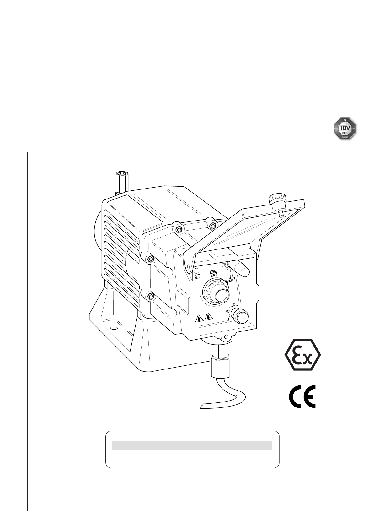
Metering Pump ProMinent EXtronic® EXBb
®
ProMinent
EXBb
The operating instructions contain changes in the electrical safety parameters.
Please carefully read through these operating instructions in full! Do not discard!
The operator shall be liable for any damage caused by installation or operating errors!
Part No. 987094 ProMinent Dosiertechnik GmbH · 69123 Heidelberg · Germany BA EX 014 01/12 EN
___ ___ ___ ___ ___ ___ ___ ___
Please enter identcode of the device here!
It replaces all earlier operating instructions.
Page 2

Publishing details
Page 2
Publishing details:
Operating Instructions Metering Pump ProMinent EXtronic® EXBb
© ProMinent Dosiertechnik GmbH, 2003
ProMinent Dosiertechnik GmbH
Im Schuhmachergewann 5-11
69123 Heidelberg
Germany
info@prominent.com
www.prominent.com
Subject to technical modificatios.
ProMinent
®
Page 3
View of Metering Pump
1
2
3
4
5
6
7
8
9
12
14
15
13
11
16
10
17
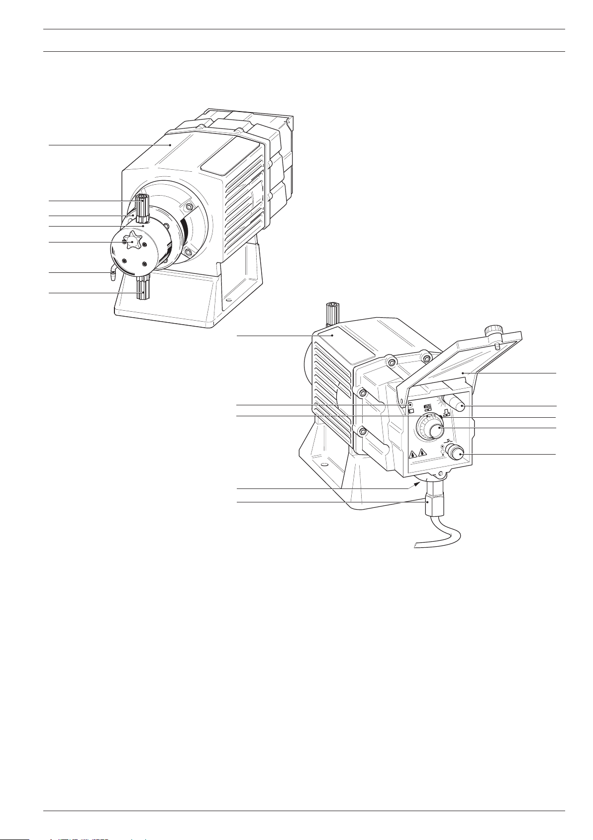
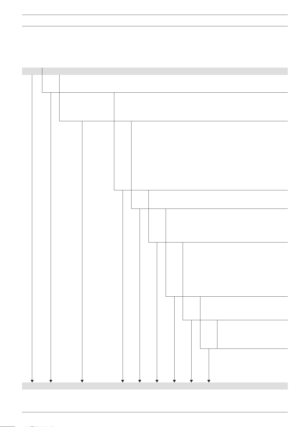
View of Metering Pump
Description of Functional Elements
1 Drive unit with electronic control and solenoid
2 Delivery connection
3 End ring
ProMinent
®
4 Liquid end
5Vent valve (only on types 1000 - 0417 NP and PP, refer to identcode on Page 13)
6 Socket for bypass hose (only on types 1000 - 0417 NP and PP, refer to identcode on Page 13)
7 Intake connection#
8Type identification plate
9 Operating/impulse display
10 Inspection window
11 External connection
12 Power connection
13 Mains switch (not for 500 V version)
14 Control for stroke length
15 Locking lever
16 Control knob for stroke rate or pushbutton/pushbutton switch for priming
17 Transparent cover
Page 3
Page 4

Page 4
ProMinent
®
Page 5

Contents
View of Metering Pump ......................................................................................................................................................... 3
Description of Functional Elements
Notes for User
.............................................................................................................................................................................. 7
Metering Pump Applications
............................................................................................................................ 3
............................................................................................................................................. 8
Contents
1 Safety
2 Design and Function
.................................................................................................................................................................................................. 9
1.1 Notes on Safety
1.2 Reference Guidelines/Standards
1.3 Tests and Approvals
2.1 Functional principle
............................................................................................................................................................. 9
..................................................................................................................... 9
................................................................................................................................................... 10
............................................................................................................................................................ 10
.................................................................................................................................................... 10
2.2 Construction / functional description, diaphragm rupture detector
2.3 Delivery capacity
2.4 Versions
................................................................................................................................................................................ 12
3Technical Data
3.1 Identcode
3.2 Dimensions and Weights
3.3 Capacity data
3.4 Accuracies
3.5 Material Specifications
3.6 Electrical Data
3.6.1 Electrical data, control current circuit
........................................................................................................................................................... 11
............................................................................................................................................................................ 13
............................................................................................................................................................................ 13
........................................................................................................................................ 14
.................................................................................................................................................................. 15
......................................................................................................................................................................... 16
............................................................................................................................................. 16
................................................................................................................................................................. 16
.......................................................................................... 16
3.6.1.1 for “non-intrinsically safe” version and
“intrinsically safe” version
3.6.1.2 under “intrinsically safe” version
3.6.2 Electrical data, supply current circuit
3.6.2.1 for “not intrinsically safe” version
3.6.2.2 for the “intinsically safe” version
.............................................................................................. 16
............................................................................... 17
........................................................................................... 17
............................................................................. 17
............................................................................... 17
3.6.3 Electrical data for the intrinsically safe (optional)
diaphragm rupture indicator
3.6.4 Electrical data, details
3.7 Mechanical data, cables
3.8 Ambient conditions
..................................................................................................................................................... 19
......................................................................................................................................... 18
................................................................................................................ 18
................................................................................................................................. 18
.................................... 10
ProMinent
4 Unpacking
5 Mounting and Installation
5.1 Installing Metering Pump
5.2 Installing Hose Lines
5.3 Installation Examples, Mechanical/Hydraulic
5.4 Electrical Installation
®
...................................................................................................................................................................................... 19
................................................................................................................................................ 20
....................................................................................................................................... 20
.................................................................................................................................................. 20
5.2.1 Installing the Intake Line
5.2.2 Installing the Delivery Line
5.2.3 Installing the Bypass Vent Line (see fold-out page)
.................................................................................................................................................. 25
......................................................................................................................... 21
.................................................................................................................... 22
.......................................................... 22
........................................................................................ 23
Page 5
Page 6

Contents
6 Operation ........................................................................................................................................................................................ 26
6.1 Start-Up
6.2 Determining the Delivery Capacity
6.3 Nomograms
6.4 Setting the Delivery Capacity
............................................................................................................................................................................... 26
................................................................................................................. 27
...................................................................................................................................................................... 29
............................................................................................................................. 37
7 Maintenance
8 Repairs
8.1 Replacing working diaphragm / safety diaphragm
8.2 Servicing diaphragm rupture detector
................................................................................................................................................................................ 37
.............................................................................................................................................................................................. 38
............................................................................ 38
......................................................................................................... 39
8.3 Replacing separating diaphragm in the diaphragm rupture detector
8.4 Checking diaphragm rupture detector
9 Malfunctions
................................................................................................................................................................................ 40
9.1 Operation/pulse indicator does not light, no stroke movement
........................................................................................................ 39
.............................................. 40
9.2 Pump intake no longer operable despite full stroke movement and venting
9.3 Pump no longer meters, although operation/pulse indicator lights
9.4 Liquid Emerges from end ring
............................................................................................................................ 40
9.5 Pump does not reach high pressures
or no suction despite max. stroke action
9.6 Diaphragm rupture indicator triggers alarm
10 Used Part Disposal
11 Spare parts
.................................................................................................................................................................................... 43
Installation data
................................................................................................................................................................ 42
........................................................................................................................................................................... 46
Guarantee claim for metering pumps
Declaration of Complete Dafety
EC Declaration of Conformity
EC Model Certificate
............................................................................................................................................................... 50
..................................................................................................................................... 48
.......................................................................................................................................... 49
........................................................................................................................ 47
.................................................................................................. 42
................................................................................................. 42
................................. 39
............... 40
..................................... 40
Page 6
ProMinent
®
Page 7
Notes for User
Notes for User
Please read the following instructions carefully. They will help you make the best use of this
manual.
The following are highlighted in the text:
• Numbered points
왘 Instructions
Operating guidelines:
NOTE
Notes are intended to make your work easier.
and safety instructions:
WARNING
Describes a potentially hazardous situation.
If not avoided may result in fatal or severe injury.
CAUTION
Describes a potentially hazardous situation.
If not avoided, could result in slight or minor injury or damage to property.
IMPORTANT
Describes a potentially damaging situation.
If not avoided may result in damage to property.
ProMinent
®
Page 7
Page 8
Metering Pump Applications
Metering Pump Applications
The ProMinent EXtronic® EXBb is an electronically controlled, explosion-proof diaphragm
metering pump with a short-stroke solenoid.
Liquid media The pump is used for metering liquid media:
• in explosion-threatened workplaces in zone 1, device category II 2 G of explosion group II C
(EXBbG) according to VDE guidelines
• for firedamp-threatened underground excavations in explosion group I, device category
1 M 2 (EXBbM) according to VDE guidelines
• in industrial premises at risk of explosion according to FM and CSA standards
Liquid ends made of various materials cover virtually all applications:
• Polypropylene (PP)
• PVC
• Acrylic
• PTFE-Teflon
• Stainless steel
Gas-emitting media Self-venting liquid ends made of Acrylic or PVC are available for metering gas-emitting media.
Combustible media
®
WARNING
For combustible media only use the "SB” dosing head.
IMPORTANT
The pump is not designed to meter gaseous media as well as solids.
Voltages Versions are available for various voltages and frequencies:
230 V, 115 V, 500 V, 100 V und 200 V;
50/60 Hz.
Compatibility The ProMinent EXtronic
®
EXBb is a continuation of the former EXBa series:
The external dimensions and securing holes are identical and the hydraulic accessories of these
series can be used.
The liquid ends are compatible with the other diaphragm metering pumps, with the exception of
versions „SB _“ and „_ _ M“ (see Identcode page 13).
Page 8
ProMinent
®
Page 9
Safety
1 Safety
1.1 Notes on Safety
WARNING
• Immediately switch off the pump in the case of emergency!
Use the pump power switch or an emergency stop switch in your working environment!
• When installing the metering pump also observe the installation instructions for
devices in explosive areas; for Europe the European operator directive 99/92/EC
(ATEX137) and the ATEX Product Directive 94/9/EC (ATEX 95), implemented in Germany
by the new health and safety legislation!
• When using the metering pump for metering flammable media, observe (in Europe) the
European Operator Guideline 99/92/EC (ATEX 137, previously ATEX118a), implemented
in Germany with the new operating safety directive and the German dangerous
chemicals directive.
• Observe also all relevant standards e.g. DIN EN 60079-10/14 and DIN VDE 60079-11 for
installations in explosion-threatened areas and DIN VDE 0118 for the installation of
electrical equipment in explosion-threatened areas by day.
• Note all national directives which apply to the installation when installing outside
Germany.
CAUTION
• Pumps must be accessible at all times to facilitate operation and maintenance.
Do not obstruct or block access routes!
• Only specially trained and authorized persons are permitted to maintain and repair
metering pumps and their peripheral equipment!
• Always depressurize the liquid end first before carrying out any work on the pump!
• If hazardous or unknown metering media are used, discharge and flush the liquid end
before carrying out any work on the pump!
• Observe the safety data sheets of the metering liquids!
• Always wear protective clothing (goggles, gloves) when handling hazardous or
unknown liquids! This applies in particular to working on the liquid end!
®
• Assembly of ProMinent
metering pumps with parts not tested and approved by
ProMinent is prohibited and can result in damage to persons and property, for which
no liability will be accepted!
IMPORTANT
• Adjust the stroke length only with the pump running when the load on the stroke length
setting pin is relieved temporarily!
Release the lock before adjusting the stroke length!
• Only use clamping rings and hose sockets suitable for the relevant hose diameter as
well as genuine ProMinent hoses with the specified hose dimensions and wall
thickness, otherwise the stability of the connection cannot be guaranteed!
ProMinent
NOTE
•Avoid reducing the hose sizes!
• Use the next higher pipe cross-section or a pulsation damper for long hose lines and
media with higher viscosity!
1.2 Reference Guidelines/Standards
see EC conformity declaration
®
Page 9
Page 10

Safety / Design and Function
1.3 Tests and Approvals
Explosions protection The conformity certificate of the DMT-Gesellschaft für Forschung und Prüfung mbH, department
for the safety of electric resources, exploring drifts, can be found in the appendix.
Device type Identification mark Approval
EXBbG II 2G Ex d IIC T6 Gb II 2G c IIC T6 Gb DMT 03 ATEX E 023
EXBbG, intrinsically safe II 2(1)G Ex d [ia Ga] IIC T6 Gb II 2G c IIC T6 Gb DMT 03 ATEX E 023
EXBbM I M2 Ex d I Mb I M2 c I Mb DMT 03 ATEX E 023
ExBbM, intrinsically safe I M2(M1) Ex d [ia Ma] I Mb I M2 c I Mb DMT 03 ATEX E 023
EXBbG Class l, Div.1, Group B, C and D, T6 FMR
EXBbG Class l, Div.1, Group B, C and D, T6 CSA
2 Design and Function
You will find the view of the metering pump and the description of the function units on the foldout page of the cover.
®
The metering pump ProMinent EXtronic
Drive unit (1) With electronic control and solenoid,
power connection (10)
Input “external control” (optional) (11);
Delivery unit End ring (3) with diaphragm which is stabilised by a steel core.
Liquid end (4) with delivery connection (2) and intake connection (7),
on types 1000-0417 NP and PP with bypass hose socket (6) and vent valve (5);
Operator control unit with operating/pulse display (9),
Mains switch (not for 500 V version) (13),
Stroke length control knob (14) with observation window (10),
Locking lever (15),
Control knob for stroke rate or pushbutton/pushbutton switch for priming (16) and
transparent cover (17).
consists of the main components
2.1 Functional principle
Metering is based on the pulse burst principle:
A pulse produces a magnetic field around the solenoid,
the solenoid attracts a moving thrust piece,
as a result, the diaphragm displaces the medium in the liquid end via a pressure control valve,
the valve closes on the intake side.
The magnetic field decays on completion of the switch-on pulse,
the thrust piece of the solenoid is reset by a reset spring,
the diaphragm returns to its initial position, thus initiating an intake stroke,
which closes the pressure valve and the media is drawn in on the intake side.
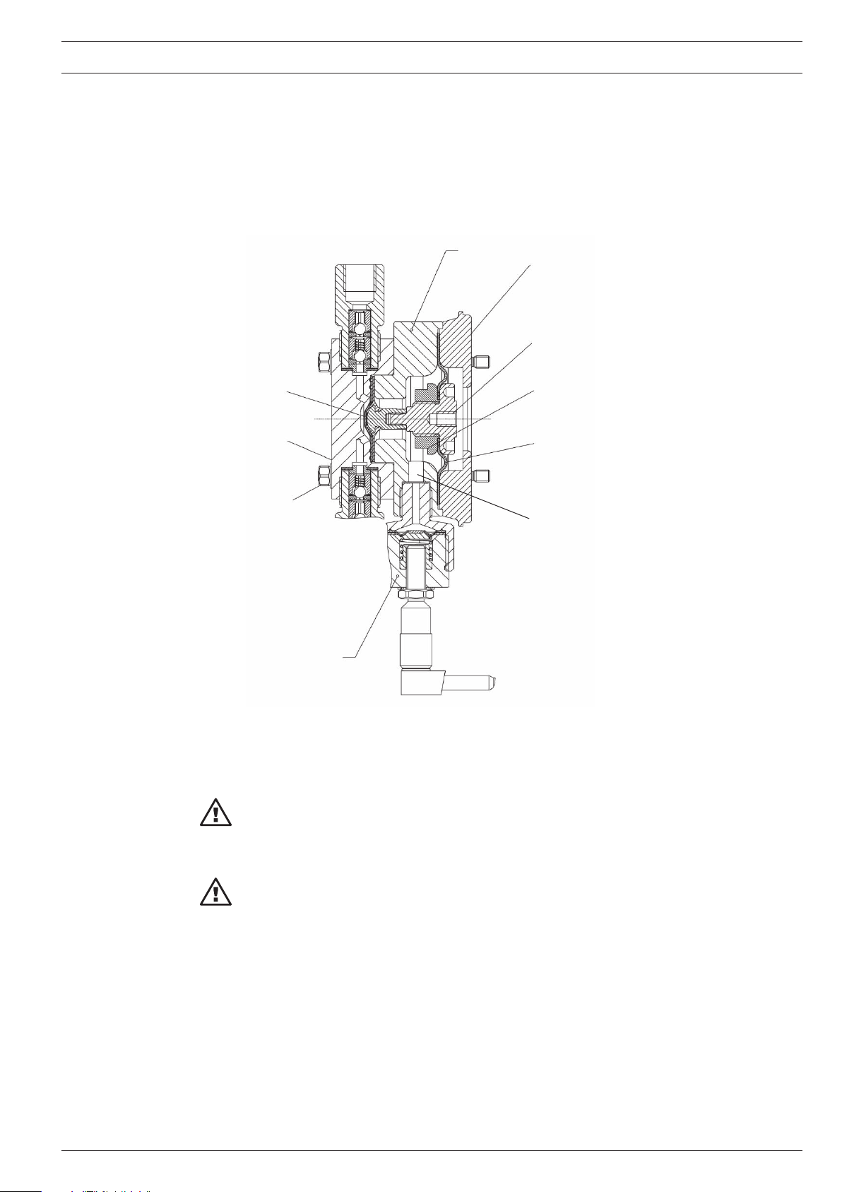
2.2 Construction / functional description diaphragm rupture indicator (optional)
The diaphragm rupture signalling system monitors the leak-tightness of the operating
diaphragm.
The liquid end of EXBb with diaphragm rupture signalling has instead of only one operating
diaphragm an additional diaphragm comprising the operational diaphragm and an additional
safety diaphragm, and is equipped with an intrinsically safe diaphragm rupture sensor (see
figure 1).
Page 10
ProMinent
®
Page 11
Design and Function
The safety diaphragm is situated between the top plate and the spacer plate and forms a sealed
interim chamber with the working diaphragm.
Function It serves to monitor ruptures in the working diaphragm and protects the power end from
corrosion and the environment from chemical leaks in the case of diaphragm rupture.
Even after diaphragm rupture, this liquid end can continue to operate in emergency mode at full
working pressure and without leaks until the diaphragm is changed.
5
1
2
6
3
1Top plate
7
4
2Adapter
3 Intermediate bush
8
10
4 Safety diaphragm
(Backup diaphragm)
5 Spacer
6Working diaphragm
7 Liquid end
8 Locking screw
9
9 Diaphragm rupture indicator
10 Intake line
fig.: 1
IMPORTANT
If the diaphragm ruptures, an electrical signal is triggered when the system back pressure
reaches approx. 2 bar.
IMPORTANT
Precise pump feed cannot be guaranteed after a working diaphragm rupture.
2.3 Feed rate
The delivery capacity is determined by the stroke length and the stroke frequency (rate).
The stroke length can be steplessly adjusted with the control knob for stroke length (14) during
operation from 100 % to 10 % and then locked. The maximum stroke length is 1.25 mm, 0.63
mm for type EXBb_1000.
A setting of 0 to 110 (120) stroke/min can be set manually with the control knob for stroke
frequency (rate) (16).
At a maximum stroke length and rate and a max. backpressure of 1.5 bar to 25 bar, the
diaphragm-operated metering pumps deliver at a rate of 0.2 l/h to 60 l/h.
ProMinent
®
Page 11
Page 12

Design and Function
2.4 Control types
Version “Internal stroke rate setting” (identity code characteristic “Control type”: 0):
The controlling pulse is internally generated, stroke length and stroke rate can be manually
adjusted using the control buttons on the operating panel.
Versions “External contact control” (identity code characteristic “Control type”: 1, 4):
The controlling pulse is externally generated, from potential-free or semiconductor contacts and
fed to the drive unit via the “external control” jack; examples are contact water meter or
DULCOMETER® controls.
Versions “Analog control x - 20 mA”
(Identity code characteristic “Control type”: 2, 3, 5, 6):
An external, analogue signal is fed to the drive unit via the “External control” jack;
the stroke rate changes proportionally according to the 0 .. 20 mA or 4 .. 20 mA signal.
Versions “Internal stroke rate setting with pause function”
(Identity code characteristic “Control type”: 7, 8):
As for version “Internal stroke rate setting”, however there is also the possibility of switching the
metering on and off via an external semiconductor contact or potential-free contact.
NOTE
All control types, that can be controlled via an input, can be supplied with an “External
control” input of “non-intrinsically safe” or “intrinsically safe” type [i, a].
Page 12
ProMinent
®
Page 13
3Technical Data
3.1 Identcode
EXBb Series ProMinent EXtronic® Version b
Type of enclosure
G Gas-explosion protection, explosion group IIC, device group/category II 2G;
M Mining/firedamp, and gas-explosion protection, expl. value I/IIC) device size/category I M2 U. II 2G)
1000 1601 1201 0803 1st and 2nd digit: Backpressure [bar]
1002 0308 2501 2502 3rd and 4th digit: Capacity [l/h]
1006 0613 0417 2505
1310 0814 0430 0260
Technical Data
Pump type
Liquid end material
NP1 Acrylic with vent, Viton
NP3 Acrylic with vent, Viton®-B O-Ring
NS3 Acrylic self-degassing, Viton®-B O-Ring
PP1 PP with vent, EPDM O-Ring
PP4 PP without vent/HV, EPDM O-Ring
PS3 PVC self-degassing, Viton®-B O-Ring
SB1 Stainless steel* with internal thread, Rp 1/4 bzw. 1/2 *) Material No. 1.4571
SS1 Stainless steel* with clamping rings PTFE-gasket *) Material No. 1.4571
SSM as SS1, with diaphragm rupture detector
SBM as SB1, with diaphragm rupture detector
SS2 Stainless steel* w. internal thread. 1/4"-NPT, PTFE-gasket *) Material No. 1.4571
TT1 PTFE +25 % carbon, PTFE-gasket
Valve spring
0 no valve spring
1 with 2 valve springs (1.4571) 0,1 bar
A 230 V 50/60 Hz open End
B 115 V 50/60 Hz open End
C 200 V 50/60 Hz open End
D 100 V 50/60 Hz open End
E 500 V 50/60 Hz open End
®
-A O-Ring
Electrical connection
Control type
0 internal stroke rate adjustment
1 external contact activation
2 analogue activation 0–20 mA
3 analogue activation 4–20 mA
4 external contact activation [i,a]
5 analogue activation 0–20 mA [i,a]
6 analogue activation 4–20 mA [i,a]
7 internal stroke rate adjustment with pause function
8 external stroke rate adjustment with pause function [i,a]
Control variant
0 with potentiometer
1 with push-button for ma. frequency
2 with switch for ma. frequency
Approval/voltage/language
0 BVS-Europa/100–500 V/German
1 BVS-Europa/100–500 V/English
2 FM-USA/100–500 V/English
3 CSA-Kanada/100–500 V/English
EXBb ___ ______ ____ ___ ___ ___ ___ ___
Viton® is a registered trademark of DuPont Dow Elastomers.
ProMinent
®
Page 13
Page 14
10
20
30
40
50
60
70
100
1
0
19
0
50
10
20
30
40
60
70
80
90
125
144
G
Technical Data
PP=11,5
Nicht u nter
Spannun g
öffnen !
D
NP=13
C
E
B
Ø 5,8
226
141
306
A
149
F
31
32
93
F
81
Version ,,NS, PS“ Version ,,SB“
*) Vent valve and bypass only on
Typs 1000 – 0417 NP and PP
*) see diagram
Page 14
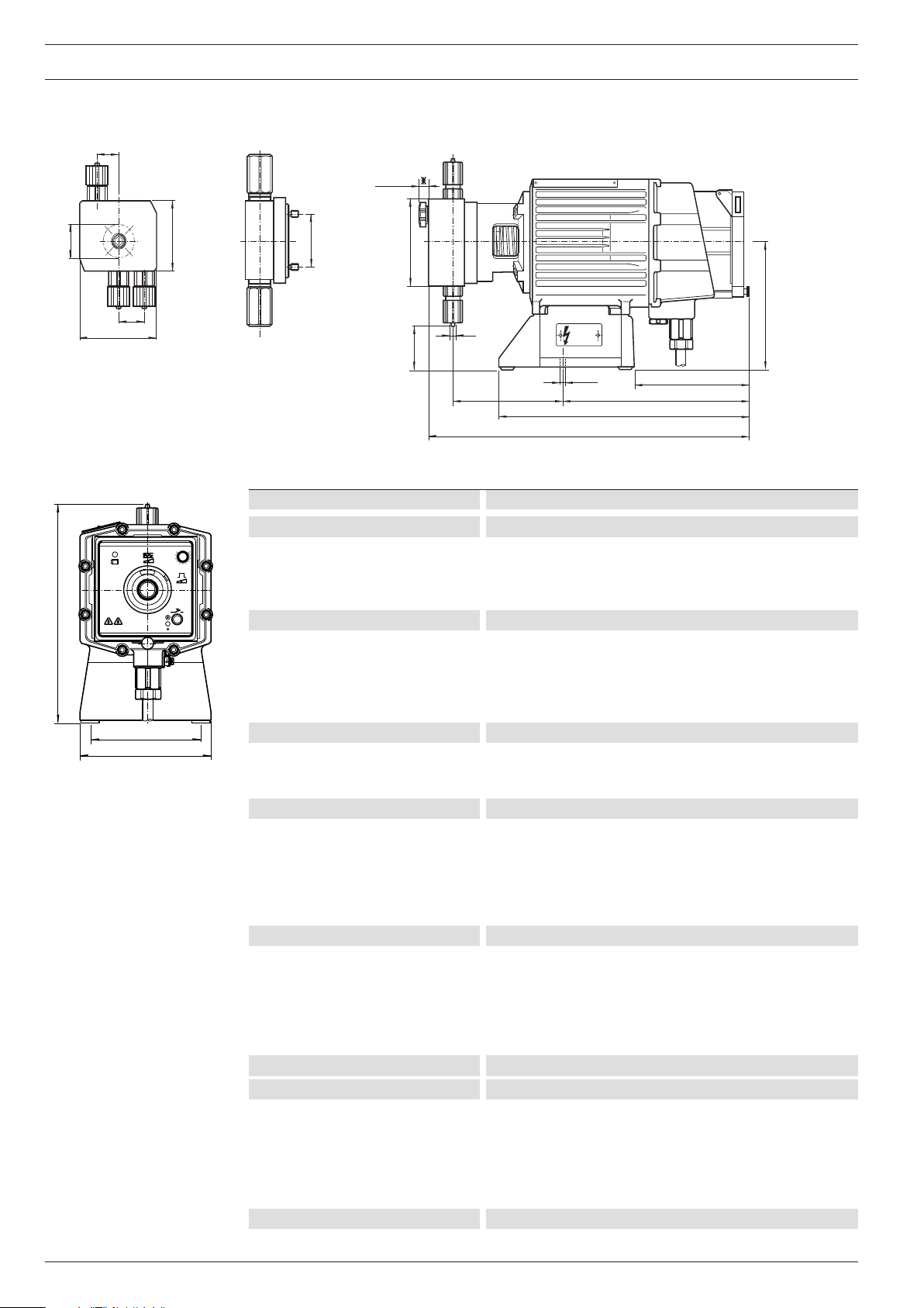
3.2 Dimensions and Weights
fig.: 2
ProMinent EXtronic® EXBb dimensions in mm
Pump type / material A B C ø D E ø F G
1000,1601, 1201, 0803 NP1 391 136 69 70 6x4 38 229
1002, 0308, 2502, 2505, 1006 NP3 391 136 61 85 8x5 50 237
1310, 0613 391 136 52 100 8x5 66 244
0814, 0417 391 136 52 100 12x9 66 244
0430 381 137 46 135 DN10 117 304
0260 398 142 -16 135 DN15 117 314
1000, 1601, 1201, 0803 PP1 393 136 67 70 6x4 38 236
1002, 0308, 1006 393 136 67 70 8x5 50 236
0613 393 136 57 90 8x5 66 246
0814, 0417 393 136 57 90 12x9 66 246
0430 381 137 46 135 DN10 117 304
0260 398 142 -16 135 DN15 117 314
1002 PP4 389 138 46 85 DN10 50 222
1006 398 145 76 85 DN15 50 222
1310 398 145 76 85 DN15 66 222
0814 398 145 69 100 DN15 66 229
1000, 1601, 1201 TT1 378 134 75 60 6x4 38 223
0803 378 134 70 70 6x4 38 228
1002, 0308, 1006 388 138 42 80 8x5 50 256
0613 388 138 32 95 8x5 66 266
0814, 0417 388 138 32 95 12x9 66 266
0430 388 137 35 135 DN10 117 263
0260 398 142 31 135 DN15 117 268
1000, 1601, 1201 SS1 376 134 84 60 6x5 38 214
0803 376 134 79 70 6x5 38 219
1002, 0308, 2502, 2505, 1006 386 138 48 80 8x7 50 250
1310, 0613 386 138 39 95 8x7 66 259
0814, 0417 386 138 39 95 12x10 66 259
0430 386 137 35 135 DN10 117 263
0260 390 142 28 135 DN15 117 271
1601, 2501 SSM 391 149 84 60 6x5 38 214
1000 SB1 373 134 87 70 Rp 1/4 38 211
1601, 1201, 0803 373 134 79 85 Rp 1/4 38 219
1002, 0308, 2502, 2505, 1006 381 138 56 80 Rp 1/4 50 242
1310, 0613 381 138 48 95 Rp 1/4 66 250
0814, 0417 381 138 48 95 Rp 1/4 66 250
0430 381 138 22 145 Rp 1/4 117 275
0260 383 139 27 145 Rp 1/2 117 279
1601, 2501 SBM 388 149 79 85 Rp 1/4 38 219
ProMinent
®
Page 15

Technical Data
1601, 1201, 0803 NS3 383 136 67 * 6x4 38 243
1002 383 136 67 * 6x4 50 243
1601, 1201, 0803 PS3 383 136 67 * 6x4 38 243
1002 383 136 67 * 6x4 50 243
Pump type Material Weight
EXBbG EXBbM
1000, 2501,1601, 1201, 0803, 1002, 0308 NP, PP, TT, SS, SB approx. 12/16 kg approx. 26/30 kg
2502, 1006, 0613, 0417 NP, PP, TT, SS, SB approx. 13/17 kg approx. 27/31 kg
2505, 1310, 0814, 0430, 0260 NP, PP, TT, SS, SB approx. 16/20 kg approx. 30/34 kg
3.3 Capacity data
Pump max. Capacity max. Capacity Stroke rate Connection- Suction Priming Perm. adtype at max. at medium size lift* lift** mission pres.
backpressure backpressure ä Ø x i Ø intake side
EXBb bar l/h ml/stroke bar l/h ml/stroke strokes/min mm m Wc m Wc bar
1000 10 0.19 0.27 5 0.27 0.038 120 6x4 1.5 0.5 8.0
2501 SSM 25 1.14 0.16 12 1.4 0.18 120 6x4 5 1.8 8.0
1601 SSM 16 1.31 0.18 8 1.68 0.23 120 6x4 5 1.8 8,0
1601 16 1.00 0.14 8 1.3 0.18 120 6x4 5 1.8 8.0
1201 12 1.70 0.24 6 2.0 0.28 120 6x4 5 2.5 5.5
0803 8 3.70 0.51 4 3.9 0.54 120 6x4 5 2.8 3.0
1002 10 2.30 0.32 5 2.7 0.38 120 8x5 5 1.0 3.0
0308 3 8.60 1.20 1.5 10.3 1.43 120 8x5 5 1.8 1.5
2502 25 2.00 0.28 12 2.4 0.31 120 8x5 5 1.0 8.0
2505 25 4.20 0.64 12 5.3 0.73 110 8x5 5 1.5 3.5
1006 10 6.00 0.83 5 7.2 1.00 120 8x5 5 1.3 3.5
1310 13 10.50 1.59 6 11.9 1.80 110 8x5 5 1.9 2.0
0613 6 13.10 1.82 3 14.9 2.07 120 8x5 5.5 1.9 2.0
0814 8 14.00 2.12 4 15.4 2.33 110 12x9 5 2.0 1.5
0417 3.5 17.40 2.42 2 17.9 2.49 120 12x9 4.5 2.0 1.5
0430 3.5 27.00 4.09 2 29.5 4.7 110 DN10 5 1.8 0.8
0260 1.5 60.00 9.09 - - - 110 DN15 1.5 1.5 0.8
Type 1000
Type 2502, 2505, 1310 only in version NP and SS
Metering pumps for high viscosity media “HV”
EXBb bar l/h ml/stroke bar l/h ml/stroke strokes/min mm m Wc m Wc bar
1002 10 2.30 0.31 5 2.7 0.38 120 DN10 1 - 3.0
1006 10 6.00 0.83 5 7.2 1.00 120 DN15 1.3 - 3.5
1310 10 10.50 1.59 6 11.9 1.80 110 DN15 1.9 - 2.0
0814 8 14.00 2.12 5 15.4 2.33 110 DN15 2 - 1.5
Metering pumps with self-degassing liquid end***
EXBb bar l/h ml/stroke bar l/h ml/stroke strokes/min mm m Wc m Wc bar
1601 16 0.66 0.09 - - - 120 6x4 - 1.8 0.2
1201 12 1.0 0.14 - - - 120 6x4 - 2.0 0.2
0803 8 2.4 0.33 - - - 120 6x4 - 2.8 0.2
1002 10 1.8 0.25 - - - 120 6x4 - 2.0 0.2
*) Suction lift: with intake line filled
**) Priming lift: with intake line not filled
***) The specified performance data are guaranteed minimum values determined with water at room temperature.
ProMinent
®
Page 15
Page 16

Technical data
3.4 Accuracies
min.: -5 %, max.: not specified
at max. stroke length and max. backpressure,
in all material versions.
Better than ± 2 %
under constant conditions and min. 30 % stroke length;
observe following notes:
• All specifications refer to metering measurements with water at 20 °C.
• Constant backpressure, above 1 bar if possible.
• If metering takes place via a free outlet, a pressure retention valve must be used to generate
a backpressure of min. 1.5 bar (refer to the installation examples).
• Wherever possible, lay intake and metering lines with a constant rising gradient.
• If the liquid level of the supply tank is above the pump during operation, admission pressure
will be applied on the intake side; in this case, the backpressure should be so high that there
is a minimum differential pressure of 1.5 bar otherwise a pressure retention valve or a springloaded injection valve with corresponding admission pressure must be used.
NOTE
A pressure retention valve or a spring-loaded injection valve is not an absolutely tightclosing shut-off element. For this reason, an intake valve which is closed when the
metering pump is at a standstill, must be installed if admission pressure is applied on the
intake side.
Liquid end
Intake- / delivery
connection
Seals
Balls Ø 6–Ø 12
Balls DN10–DN15
3.5 Material Specifications
PP1 PP4 PC5 NP1/NP3 NS3 PS3 TT1 SS
Polypropylene Polypropylene PVC Acrylic Acrylic PVC PTFE with Stainless steel
Polypropylene Polypropylene PVC PVC PVC PVC PTFE with Stainless steel
EPDM EPDM FPM-A FPM-A/B FPM-B FPM-B PTFE PTFE
Ceramic — Ceramic Ceramic Ceramic Ceramic Ceramic Ceramic
Duran Ceramic — Duran — — Ceramic 1.4401
Type 1000 with ceramic seat rings in all material versions
PP4 with Hastelloy C valve springs
DEVELOPAN
FPM-A (Viton®-A), FPM-B (Viton®-B) and Duran (laboratory glass) are registered trademarks.
®
metering diaphragm with PTFE base in all versions
carbon 1.4404
carbon 1.4404
3.6 Electrical Data
3.6.1 Electrical data, control current circuit
3.6.1.1 for “non-intrinsically safe” version and “intrinsically safe” version
mA input, identity code feature “control type”: 2, 3, 5*, 6*
Voltage max. 6 V
Current max. 30 mA
Input apparent ohmic resistance, approx. 94 Ω
Page 16
ProMinent
®
Page 17

Contact/pause input, identity code feature “control type”: 1, 4*, 7, 8*
Voltage with open contact approx. 5 V
Input resistance approx. 4.7 kΩ
Control using potential-free contact or semiconductor switch:
Residual current max. (contact open): 70 µA
Contact resistance (closed) max.: 10 kΩ or
Voltage drop max.: 3 V
Pulse frequency max.: 40 pulses/sec.
Pulse width min.: 10 ms
* For the ensuring of intrinsic-safety, see chapter 3.6.1.2 under "intrinsically safe" version
3.6.1.2 under “intrinsically safe” version
Control circuit Default value of all types “(ia)”,
• Maximum output voltage: U
• Maximum output current: I
• Maximum output power: P
• Internal resistance R
• Maximum external inductance: L
• Maximum external capacity: C
= 7.14 V
0
= 5 mA
0
= 23.3 mW
0
= 4296 Ω
i
=1 H
0
= 13.5 µF
0
Technical data
For connection of an intrinsically safe circuit
• Maximum input current: I
• Maximum input voltage: U
• Maximum input power P
•Effective inner self-inductance L
•Effective inner capacity C
= 280 mA
i
= 30 V
i
=2 W
i
= negligible
i
= negligible
i
3.6.2 Electrical data, supply current circuit
3.6.2.1 for “not intrinsically safe” version
Measurement voltage 100,115, 200, 230 and 500 + - 10 % VAC
Maximum current consumption I
Max. peak current during a stroke I
Maximum power consumption P
* 1.5 A
eff
peak
* 50 W
wirk
8 A
* obtained by averaging over several strokes at the maximum stroke rate
3.6.2.2 for the “intinsically safe” version
Supply current circuit Intrinsically safe rated voltage: 100, 115, 200, 230 + - 10%, 500 +6% -10% VAC
Maximum current consumption I
Max. peak current during a stroke I
* 1.5 A
eff
peak
8 A
Maximum power consumption Pwirk* 50 W
* obtained by averaging over several strokes at the maximum stroke rate
ProMinent
®
Page 17
Page 18

Technical data
3.6.3 Electrical data for the intrinsically safe (optional) diaphragm rupture indicator
Diaphragm rupture detector Type Pepperl+Fuchs, NJ1,5-8GM-N-V1
Nominal voltage 8.2 V (Ri approx. 1 kOhm)
Normal power consumption ≤ 1mA
Power consumption in the event of a diaphragm rupture ≥ 3mA
Please observe the Operating Manual and the Type Examination Certificate of the diaphragm
rupture sensor for detailed data and for use in areas at risk of explosion.
3.6.4 Electrical data, details
Pump type 1000, 2501,1601, 1201, 2502, 1006, 0613, 0417, 2505, 1310, 0814, 0430, 0260
Mains connection (V) 100 115 200 230 500 100 115 200 230 500 100 115 200 230 500
Max. current consumption*** (A) 1.6 1.4 0.7 0.8 0.3 3.0 2.7 1.8 1.8 0.6 4.1 3.6 2.2 2.5 1.1
Effective. current
consumption*** (A)
Mean power consumption (W) 16 16 16 16 16 35 35 35 35 35 47 47 47 47 47
Fuse item 65* value (A)/Type 1.0T 0.63T 0.4T 0.315T 0.319 2.5T 2.0T 1.25T 0.8T 0.63 3.15T 2.5T 1.6T 1.25T 1.25
Value (A)/Type 0.16T 0.16T 0.16T 0.16T - 0.16T 0.16T 0.16T 0.16T - 0.16T 0.16T 0.16T 0.16T -
0.27 0.29 0.14 0.17 0.09 0.70 0.70 0.33 0.41 0.14 0.95 0.84 0.47 0.53 0.25
0803, 1002, 0308 1002*****
* special fuse with high switching capacity: only use original fuse
** use only original fuse
*** effective value during a stroke
**** obtained by averaging over several strokes at the maximum stroke rate
*****with material version PP4
Fuse order numbers, see chapter 11
NOTE
Only the effective power consumption is specified on the rating plate
3.7 Mechanical data, cables
Pump type Voltage V Cable Cable type Colour outer Ø mm
EXBbG to 250 power cable H 07 RNF 3G1.5 black 10.0
EXBbG > 250 power cable NSSHÖU 3x1.5 yellow 12.5
EXBbM all power cable NSSHÖU 3x1.5 yellow 14.0
+3x1.5/3E
EXBbG < 60 external/analogue cable Ölflex 110 grey 6.3
EXBbG < 60 external/analogue cable Ölflex EB blue 5.9
EXBbM < 60 external/analogue cable L-YY (zg) Y grey 11.4
EXBb_ 8 diaphragm rupture detector blue
In “FM”- and “CSA” version H07 RNF up to 500 V, the cable aperture has
a 1/2" NPT internal thread for connection to the North American supply system.
Page 18
ProMinent
®
Page 19

3.8 Ambient conditions
Admissible storage temperature -20 °C to +50 °C
Admissible ambient temperature -20 °C to +45 °C
Admissible chemical temperature -10 °C to +35 °C (in accordance with IEC 335-2-41)
Temperature resistance of material versions
Long term at max. back pressure 50 °C 45 °C 50 °C 50 °C
Max. 15 min at max. 2 bar 100 °C 60 °C 120 °C 120 °C
Climate admissible humidity 92 % non condensing
Behaviour in damp alternating climate DIN IEC 60068-2-78
Enclosure rating IP 65
Sound intensity level ≤ 70 dB (A), 1 m Abstand
4 Unpacking
NOTE
Polystyrene parts are recyclable. They do not belong in the household waste!
Technical data / Unpacking
PP NP TT SS
왘 It is advisable to keep the outside packing complete with the polystyrene parts in order to
be able to return the metering pump in the case of repairs and warranty claims.
왘 Compare your delivery note with the packed contents.
왘 Check whether the data on the type identification plate (8) of the metering pump agree with
your order data!
왘 Should any problems arise, contact your ProMinent dealer or representative. You will find the
addresses on the back page of these operating instructions.
왘 Always specify the identity code and the serial number which you will find on the type identi-
fication plate when making any inquiries or ordering spare parts. In this way, the pump type
and material variants can be clearly identified.
Scope of delivery • Metering pump with power cable
• Operating instructions with conformity certificate
• Conformity declaration for Namur-Sensor (only with diaphragm rupture indicator)
ProMinent
®
Page 19
Page 20

Mounting and Installation
5 Mounting and Installation
WARNING
• When installing the metering pump also observe the installation instructions for devices
• When using the metering pump for metering flammable media, observe (in Europe) the
• Observe valid national regulations when installing the pump abroad!
• Remove all traces of water from the liquid end before starting operation with media
5.1 Installing Metering Pump
IMPORTANT
• Secure the pump such that no vibrations can occur.
• Ensure free access to facilitate operation and maintenance.
• The valves of the liquid end must be in vertical position!
왘 The metering pump must be secured with screws and washers Ø 6 mm on a horizontal, firm
in explosive areas; for Europe the European operator directive 99/92/EC (ATEX137) and
the ATEX Product Directive 94/9/EC (ATEX 95), implemented in Germany by the new
health and safety legislation!
European Operator Guideline 99/92/EC (ATEX 137, previously ATEX118a), implemented
in Germany with the new operating safety directive and the German dangerous chemicals directive.
which must not come in contact with water! The metering pump may still have water
residue in the liquid end from the tests carried out at the factory.
base.
5.2 Installing Hose Lines
IMPORTANT
• Lay and secure intake and delivery lines such that they cannot chafe.
• Lay intake and delivery lines such that they are free of mechanical stress.
• Arrange all lines such that the pump and liquid end can be removed laterally if required.
• When metering extremely aggressive or hazardous media, a venting facility with return
into the supply tank as well as a shut-off valve must be provided on the delivery and
intake sides.
• Ensure all connections are tight:
only use the clamping rings and hose sockets as specified for the relevant hose
diameter, only use original hoses with specified hose dimensions and wall
thickness.
•Avoid reductions in hose sizes: use the next higher line cross-section for long hose
lines and viscous media or install a compressed air vessel or diaphragm pulsation
damper!
Page 20
ProMinent
®
Page 21

Fitting Hose lines 왘 Remove plug if fitted in the intake/delivery connection.
Union nut
Clamping ring
Hose
Socket
Valve
Pipe
Union nut
Rear
clamping ring
Front
clamping ring
Valve
fig.: 3
Fitting stainless steel pipe
connections 왘 Fit union nut and clamping rings on to pipe with a projection of approx. 10 mm.
Mounting and Installation
왘 Cut end of hose straight.
왘 Fit union nut and clamping ring over hose.
왘 Fit end of hose as far as it will go over socket widen end if necessary.
왘 Fit hose with socket on to valve.
왘 Clamp hose connection:
Firmly tighten union nut while at the same time pressing down hose.
왘 Retighten hose connection:
Pull the hose line secured at the liquid end and then tighten the union nut once again.
왘 Fit pipe as far as it will go into valve.
왘 Firmly tighten union nut.
fig.: 4
Fitting PE or PTFE lines on
stainless steel
valves 왘 Additionally fit a stainless steel support sleeve in the plastic sleeve.
5.2.1 Installing the Intake Line
NOTE
• The intake line should be as short as possible.
• Fit intake line in upright position in order to avoid air bubbles forming.
• Wherever possible use pipe bends and not elbows for bends in the intake line.
• Select cross section and length such that the vacuum which occurs during intake does
not reach the vapour pressure of the medium to be metered. In extreme cases,
excessively high vacuum on the intake side is reflected in collapse of the liquid column
or by an incomplete return stroke.
• Do not exceed the permissible admission pressure on the intake side.
• Note: Suction lift x medium density ≤ max. suction lift in m water column
• Refer to the installation examples.
ProMinent
®
Page 21
Page 22

Mounting and Installation
Installing foot valve 왘 Cut the free end of the intake line to size such that the foot valve just hangs over the bottom
5.2.2 Installing the Delivery Line
IMPORTANT
•A multiple of the maximum operating pressure can build up if the metering punp is
• Install the delivery line such that the pressure peaks during the metering stroke do
• Refer to installation examples!
When metering with atmospheric discharge, a metering valve with 0.5 bar response pressure
should be mounted at the end of the line. Or a back-pressure valve should be mounted directly
onto the liquid end in order to create and maintain a counter-pressure of approx. 1.5 bar.
If the level of the fluid of the supply tank is above the pump in operating condition, the response
pressure is on the suction end. In this case the counter-pressure should be sufficiently high such
that a minimum differential pressure of 1.5 bar exists. If this is not the case a back-pressure
valve or a spring-loaded metering valve with the respective response pressure should be used.
of the tank. In the case of metered solutions with impurities or bottom deposits, the foot
valve should be located at an adequate distance above the tank bottom or bottom deposits.
operated against a closed shut-off element on the delivery side.This can cause the
delivery line to burst!
An overflow valve should be installed in order to avoid this, e.g. a ProMinent multifunction valve.
not exceed the max. permissible operating pressure. Check length and cross-section.
If necessary, install an overflow valve, compressed air vessel or diaphragm pulsation
damper.
NOTE
A back-pressure valve or a spring-loaded metering valve is not an absolutely leakproof
shut-off device!
On the suction end a stop valve is therefore to be installed which is closed when the
metering pump is idle.
5.2.3 Installing the Bypass Vent Line (see fold-out page)
The liquid end of the pump types 1000 - 0417 NP and PP is equipped with a vent valve (5) with
bypass (6).
The admission pressure on the intake side must be at least the same pressure as in the bypass
line. Operation is not possible with admission pressure in the bypass and no pressure on the
intake side
왘 Fit hose line with Ø
PVC-soft 6x4 is recommended.
= 4 mm (max. 6 mm) on to bypass hose socket,
internal
왘 For PE lines, secure against slipping using a quick fastener.
왘 Route the free end of the line back into the metering tank.
왘 Cut the bypass line to size such that it is not submerged in the metering medium.
Page 22
ProMinent
®
Page 23

Mounting and Installation
5.3 Installation Examples, Mechanical/Hydraulic
Symbols Oscillating diaphragm metering pump Injection valve
Foot valve Pressure retention valve/
overflow valve
Shut-off valve Pressure retention valve (adjustable)
Standard installation
Metering with free outlet and
small delivery head
Pressure gauge
Solenoid Valve
(closed when pump switched off)
.... and large delivery head
Compressed air vessel
... and admission pressure
on intake side
Installation to avoid lift-
through of hazardous media
ProMinent
®
Page 23
Page 24

Mounting and Installation
Installation togeher with air
vessel with long lines and for
low-pulsation metering
... in a delivery line
... with free outlet
... without after-running
Delivery line
DHV-S
Nozzle
To protect against
overpressure
Do not install like this:
Intake line cannot be vented!
Do not install like this:
Free flow!
Metering in vacuum
or intake line
Do not install like this:
Intake line too high!
Do not install like this:
Compressed air vessel
not effective!
injection valve
with re-inforced
spring or DHV
Page 24
ProMinent
®
Page 25

5.4 Electrical Installation
10
20
30
40
50
60
70
100
1
0
19
0
50
10
20
30
40
60
70
80
90
23
12
IMPORTANT
• The metering pump must be electrically installed by authorised, “skilled” personnel
only.
• When installing the metering pump also observe the installation instructions for
devices in explosive areas; for Europe the European operator directive 99/92/EC
(ATEX137) and the ATEX Product Directive 94/9/EC (ATEX 95), implemented in Germany
by the new health and safety legislation!
• Observe the relevant standards e.g. DIN EN 60079, DIN EN 60079-11, DIN VDE and/or
0118 “Erecting electrical equipment in explosion-threatened areas” DIN EN 60079-14!
• Note all national directives which apply to the installation when installing outside
Germany.
• Intrinsically safe installations must be checked by persons with “recognised
qualifications“.
• Do not connect mains power supply to the external terminal (11).
• The internally used fusible link has a breaking capacity of 1,500A. If the short-circuit
current in the supply network ma be larger than 1,500A, the pump is to be protected
with a suitable back-up fuse with a higher breaking capacity (rated current smaller
than 1,500A).
Power connection Electrical data see 3.6
The connection terminal (23) for the equipotential bonding conductor is located on the housing
next to the power supply terminal (12).
Mounting and Installation
fig.: 5
12 Power supply
23 Connection terminal for
equipotential bonding
Induction voltage If the pump is connected to the power supply parallel to inductive loads (e.g. solenoid valve,
EXBbG L1: Phase, brown
N: Zero wire, blue
PE: Earth lead, yellow/green
EXBbM L1: Phase, brown
N: Zero wire, blue
-: free, black*
PE: Earth lead, yellow/green**
* Internally insulated, connect to a free terminal on the outside.
** Twist the three single coaxial earth leads together, fit yellow/green sleeve and attach to the
earth lead terminal.
motor), it must be electrically isolated from these loads in order to avoid damage caused by
induction voltages when switching off.
왘 Use several contacts for power supply via auxiliary contactor or relay.
왘 In the 100-V- to 230-V-versions, connect a varistor (U
(0,22 uF/220 Ohm) in parallel.
= 275 V) or RC-element
N
ProMinent
Varistor
Inductive
load
ProMinent
Metering pump
ProMinent
Metering pump
Varistor
Inductive
load
Abb.: 6
Switching on With power switch (13), a power switch must be provided by the customer for the 500 V version.
®
Page 25
Page 26

Mounting and Installation / Operation
External, contact, analogue and pause input, not intrinsically safe
EXBbG input+ black (1)
Input- black (2)
EXBbM input+ blue
Input- black
External, contact, analogue and pause input intrinsically safe, sheath colour blue.
EXBbG und EXBbM: Input (+) = brown (1)
El. terminal for diaphragm rupture detector, intrinsically safe, sheath colour blue.
ExBbG and EXBbM: Alarm, blue
6 Operation
6.1 Start-Up
Input (+) = blue (2)
GND+, brown
WARNING
• Always wear protective goggles and protective clothing when handling hazardous
media!
• The metering pump may still contain water residue in the liquid end from the tests
carried out at the factory. All water must be removed from the liquid end before startup in the case of media which must not come in contact with water!
NOTE
• Carry out all settings only with the pump in operation.
Release the lock before adjusting the stroke length!
• The intake head with the liquid end empty is dependent on the stroke volume:
The pump intake should be set at stroke length = 100 %. Select the intake head
correspondingly smaller if the pump is to be discharged at a lower setting without
changing the stroke length and is to be placed into operation again self-priming.
• Pump intake is not possible against backpressure
• Absolutely reliable metering cannot be guaranteed after a pump down period.
Regular monitoring is necessary!
Before start-up 왘 Check function of pressure relief valves.
왘 Check pump connections and pipe connections for leaks.
Remove water from liquid end when handling media which must not come in contact with water:
왘 Tu rn pump through 180°.
왘 Empty liquid end.
왘 Flush with a suitable medium from above through the intake connection.
Page 26
Filling liquid end without vent valve:
왘 Connect intake line but do not yet connect the delivery line to the liquid end.
왘 Switch on pump with power switch (13) and operate at max. stroke length and stroke rate
until liquid end is filled completely and free of bubbles.
왘 Switch off pump with power switch (13).
왘 Connect delivery line to liquid end.
The pump is now ready for operation.
ProMinent
®
Page 27

Filling liquid end liquid end with vent valve and bypass:
Rough venting
왘 Connect intake and delivery line to liquid end.
왘 Connect bypass line.
왘 Open vent valve (5) by one turn of the star knob in counterclockwise direction; the routes
for rough venting via the bypass (6) is now clear.
왘 Switch on pump with power switch (13) and operate at max. stroke length and stroke rate
until liquid end is filled completely and free of bubbles (when the medium is visible in the
venting or metering line).
왘 Close vent valve.
왘 Switch off pump with power switch (13).
The pump is now ready for operation
Setting fine vent metering gas-emitting media:
NOTE
•A part of the metered quantity is constantly routed back into the supply tank.
The return quantity should be approx. 20 % of the metered quantity.
• The media must be low-viscous (thin-bodied) and without solids.
• If the return flow line ends above the liquid level, the precision vent valve acts as a
vacuum breaker and prevents discharge of the supply tank if a vacuum builds up in
the metering line.
• Retighten the screws in the liquid end after 24 hours of operation.
Operation
왘 Remove star knob from vent valve (5).
왘 Using a screwdriver, turn screw in vent valve approx. 1 turn in counterclockwise direction.
왘 Fit star knob on vent valve (5).
Venting liquid end HV version:
Initial intake and venting is impaired to a certain extent by the valves and valve springs which
are still dry. Therefore select the shortest possible intake head or vent the liquid end with inlet
or admission pressure on the intake side.
If not successful, shortly operate pump without valve spring in the pressure valve:
왘 Unscrew delivery connection and press away ball from O-ring.
왘 Fill liquid end with water or suitable liquid.
왘 Fit delivery connection without valve spring.
왘 Fit short piece of PVC hose (100 mm) on to hose socket, half fill with water.
왘 Operate pump at max. stroke length until metering is visible in the hose.
왘 Re-install valve spring – avoid twisting by fitting an approx. 4 mm Ø drift through the
pressure valve in order to hold the spring in the centre position.
왘 Reconnect delivery line.
Venting liquid end when pump delivers in a pressure system and has drawn in air:
왘 Set venting on delivery side: Release metering line or open vent valve.
왘 Switch on pump and vent at stroke length 100 %.
ProMinent
6.2 Determining the Delivery Capacity
The actual delivery capacity is dependent on the stroke length, stroke frequency (rate) and
backpressure in the metering line. The relationship between capacity/stroke length/stroke
frequency (rate) is illustrated in the nomogram for each type of pump. A correction factor can
be read off from the diagram which shows the change in capacity referred to backpressure.
The measurements for determining the nomograms were conducted with water and the
correction factor was determined at a stroke length of 70 %. The capacity scatter over all
material versions is -5 % (for max. value: not specified).
®
Page 27
Page 28

Operating
왘 Select the required capacity within the value range of the pump type (see capacity data).
왘 Select the nomogram and diagram of the pump type.
왘 Mark the backpressure in the metering system on the abscissa and read off the
corresponding correction factor on the ordinate.
왘 Divide the required capacity by the correction factor.
왘 Using a ruler, mark the determined capacity on the middle scale of the nomogram.
왘 Draw a line across all three scales – as horizontal as possible, however, such that the line
intersects at least one of the two outer scales; where possible, select a graduation with a
large value on the stroke length scale.
The point of intersection of the line with the right-hand scale shows the stroke frequency (rate)
to be set, the point of intersection of the line with the left-hand scale shows the stroke length to
be set.
Capacity with mean backpressure: 11.9 l/h (see capacity data)
Required capacity: 6 l/h
Backpressure: 8 bar
→ Correction factor as per diagram: 0.9
→ Capacity to be set: 6 l/h
0.9
= 6,66 l/h
→ Stroke length as per nomogram: 80 %
→ Stroke rate as per nomogram: 80 stroke/min
NOTE
• Select large stroke length and low stroke rate for highly viscous and gas-emitting
media.
• Use self-venting liquid end for gas-emitting media with viscosity ≤ 20 mPa s.
• Select a shorter stroke length and high stroke rate for effective mixing.
• For a precise dosing, choose metering-stroke of not less than 30 %.
At max. pressure stroke length
≥ 60 % for type 1601,
≥ 40 % for type 1201 and 1002,
≥ 20 % for type 0803;
the stroke length can be reduced further at lower pressure.
• Set the stroke length greater for pumps with the precision vent open
Page 28
ProMinent
®
Page 29

EXBb_1000
0.30
0.25
0.20
0.15
0.12
0.09
0.07
0.05
0.04
0.03
0.02
0.015
0.012
0.01
0.005
0.004
5.04
4.00
3.00
2.00
1.50
1.00
0.70
0.50
0.40
0.30
0.20
0.15
0.10
0.07
1.5
1.0
0.5
0 1.5 3 4 5 6 7 8 9 10
100
90
80
70
60
50
40
30
20
10
5
120
108
96
84
72
60
48
36
24
12
6
0.625
0.563
0.500
0.438
0.375
0.313
0.250
0.188
100
90
80
70
60
50
40
30
Capacity (ml/min)
Capacity (l/h)
Backpressure (bar)
Correction factor
Capacity 0.27 l/h at medium backpressure of 5 bar
Capacity 0.19 l/h at max. backpressure of 10 bar
Capacity dependent on backpressure
Stroke length (mm)
Stroke length (%)
Stroke rate (scale)
Stroke rate (stroke/min)
1,125
1,250
1,000
0,875
0,750
0,625
0,500
0,375
100
90
80
70
60
50
40
30
100
90
80
70
60
50
40
30
20
10
5
120
108
96
84
72
60
48
36
24
12
6
1,30
0,90
0,60
0,40
0,26
0,18
0,13
0,10
0,08
0,06
0,04
0,03
0,02
0,015
0,01
21,67
16,00
13,00
10,00
8,00
6,50
5,50
4,33
3,50
2,70
2,17
1,50
1,00
0,80
0,60
0,40
0,30
0,20
Stroke length (mm)
Stroke length (%)
Capacity (ml/min)
Capacitiy (l/h)
Stroke rate (Scale)
Stroke rate (stroke/min)
Backpressure (bar)
Capacity 1,30 l/h at medium backpressure of 16 bar
Capacity 1,10 l/h at max. backpressure of 25 bar
Capacity dependent on backpressure
Correction factor
Operating
6.3 Nomograms
EXBb_2501
ProMinent
®
Page 29
Page 30

Operating
1.125
1.250
1.000
0.875
0.750
0.625
0.500
0.375
100
90
80
70
60
50
40
30
100
90
80
70
60
50
40
30
20
10
5
120
108
96
84
72
60
48
36
24
12
6
1.5
1
0.5
0
1.5
21
34567
8
910
11
12
2.00
1.60
1.30
1.00
0.76
0.60
0.50
0.35
0.25
0.20
0.15
0.10
0.08
0.06
0.04
0.03
33.33
28.00
24.00
20.00
17.00
15.00
12.67
9.50
7.50
6.00
4.50
3.33
2.50
2.00
1.50
1.25
1.00
0.80
0.70
0.60
Capacity (ml/min)
Capacity (l/h)
Backpressure (bar)
Correction factor
Capacity 2.00 l/h at medium backpressure of 6 bar
Capacity 1.70 l/h at max. backpressure of 12 bar
Capacity dependent on backpressure
Stroke length (mm)
Stroke length (%)
Stroke rate (scale)
Stroke rate (stroke /min)
1.125
1.250
1.000
0.875
0.750
0.625
0.500
0.375
100
90
80
70
60
50
40
30
100
90
80
70
60
50
40
30
20
10
5
120
108
96
84
72
60
48
36
24
12
6
1.30
0.90
0.60
0.40
0.26
0.18
0.13
0.10
0.08
0.06
0.04
0.03
0.02
0.015
0.01
21.67
16.00
13.00
10.00
8.00
6.50
5.50
4.33
3.50
2.70
2.17
1.50
1.00
0.80
0.60
0.40
0.30
0.20
1.5
1
0.5
0
1.5
4
6
8
10
12 14
16
Stroke length (mm)
Stroke length (%)
Capacity (ml/min)
Capacitiy (l/h)
Stroke rate (Skale)
Stroke rate (stroke/min)
Backpressure (bar)
Correction factor
Capacity 1.30 l/h at medium backpressure of 8 bar
Capacity 1.00 l/h at max. backpressure of 16 bar
Capacity dependent on backpressure
EXBb_1601
EXBb_1201
Page 30
ProMinent
®
Page 31

1.125
1.250
1.000
0.875
0.750
0.625
0.500
0.375
100
90
80
70
60
50
40
30
3.90
3.40
3.00
2.50
2.00
1.70
1.42
1.20
1.00
0.80
0.60
0.50
0.39
0.30
0.25
0.20
0.15
0.12
0.10
0.08
0.06
65.00
58.00
50.00
40.00
35.00
27.00
23.67
20.00
15.00
11.50
10.00
8.00
6.50
5.00
4.00
3.00
2.50
2.00
1.60
1.30
1.00
100
90
80
70
60
50
40
30
20
10
5
120
108
96
84
72
60
48
36
24
12
6
1.5
1
0.5
0
1
1.5 2
3
4
5
6
78
Stroke length (mm)
Stroke length (%)
Capacity (ml/min)
Capacity (l/h)
Stroke rate (scale)
Stroke rate (stroke/min)
Backpressure (bar)
Correction factor
Capacity 3.90 l/h at medium backpressure of 4 bar
Capacity 3.70 l/h at max. backpressure of 8 bar
Capacity dependent on backpressure
EXBb_0803
2.70
2.30
1.80
1.50
1.20
1.00
0.83
0.70
0.60
0.50
0.40
0.33
0.27
0.20
0.15
0.10
0.08
0.06
0.04
45.00
38.00
30.00
25.00
20.00
17.00
13.30
10.00
8.00
6.00
4.50
3.60
3.00
2.50
2.00
1.50
1.00
0.80
1.5
1
0.5
0 1.5 2 3 4 5 6 7 8 9 10
1.125
1.250
1.000
0.875
0.750
0.625
0.500
0.375
100
90
80
70
60
50
40
30
100
90
80
70
60
50
40
30
20
10
5
120
108
96
84
72
60
48
36
24
12
6
Capacity (ml/min)
Capacity (l/h)
Backpressure (bar)
Correction factor
Capacity 2.70 l/h at medium backpressure of 5 bar
Capacity 2.30 l/h at max. backpressure of 10 bar
Capacity dependent on backpressure
Stroke length (mm)
Stroke length (%)
Stroke rate (scale)
Stroke rate (Stroke /min)
Operating
EXBb_1002
®
ProMinent
Page 31
Page 32

10.30
8.00
6.00
5.00
4.00
3.42
2.50
2.00
1.50
1.03
0.80
0.60
0.50
0.40
0.30
0.20
0.15
171.67
150.00
120.00
100.00
80.00
65.00
57.00
47.00
40.00
30.00
25.00
20.00
17.17
13.00
10.00
8.00
6.00
5.00
4.00
3.00
1.5
1
0.5
0
0.5
1
1.5
2
2.5
3
1.125
1.250
1.000
0.875
0.750
0.625
0.500
0.375
100
90
80
70
60
50
40
30
100
90
80
70
60
50
40
30
20
10
5
120
108
96
84
72
60
48
36
24
12
6
Capacity (ml/min)
Capacity (l/h)
Backpressure (bar)
Correction factor
Capacity 10.30 l/h at medium backpressure of 1.5 bar
Capacity 8.70 l/h at max. backpressure of 3 bar
Capacity dependent on backpressure
Stroke length (mm)
Stroke lenght (%)
Stroke rate (scale)
Stroke rate (stroke /min)
100
90
80
70
60
50
40
30
20
10
5
120
108
96
84
72
60
48
36
24
12
6
3
2.5
2
1.5
0.5
0
1
0
2.5 5 7.5 10 12.5 15 17.5 20 22.5 25
1.250
1.125
1.000
0.875
0.750
0.625
100
90
80
70
60
50
2.20
1.40
1.00
0.70
0.50
0.39
0.25
0.19
0.15
0.10
0.06
0.04
0.03
0.02
36.66
22.00
15.00
10.00
6.50
4.50
3.17
2.20
1.50
1.00
0.70
0.50
0.40
Capacity (ml/min)
Capacity (l/h)
Backpressure (bar)
Correction factor
Capacity 2.20 l/h at medium backpressure of 20 bar
Capacity 2.00 l/h at max. backpressure of 25 bar
Capacity dependent on backpressure
Stroke length (mm)
Stroke length (%)
Stroke rate (scale)
Stroke rate (stroke/min)
Operating
EXBb_0308
EXBb_2502
Page 32
ProMinent
®
Page 33

1.250
1.125
1.000
0.875
0.750
0.625
100
90
80
70
60
50
3
2.5
2
1.5
1
0
02.557.5 10 12.5 15 17.5 20 22.5 25
0.5
4.80
3.80
3.00
2.50
2.00
1.65
1.30
1.00
0.85
0.60
0.45
0.35
0.25
0.20
0.15
0.10
80.00
60.00
45.00
35.00
25.00
19.00
14.17
10.00
7.57
6.00
4.00
3.00
2.00
1.50
1.00
0.08
0.08
0.06
0.04
100
90
80
70
60
50
40
30
20
10
5
110
88
99
77
66
55
44
33
22
11
5.5
Capacity (ml/min)
Capacity (l/h)
Backpressure (bar)
Correction factor
Capacity 4.80 l/h at medium backpressure of 20 bar
Capacity 4.20 l/h at max. backpressure of 25 bar
Capacity dependent on backpressure
Stroke length (mm)
Stroke length (%)
Stroke rate (scale)
Stroke rate (stroke/min)
EXBb_2505
1.125
1.250
1.000
0.875
0.750
0.625
0.500
0.375
100
90
80
70
60
50
40
30
100
90
80
70
60
50
40
30
20
10
5
120
108
96
84
72
60
48
36
24
12
6
7.20
6.00
5.00
4.00
3.00
2.00
1.53
1.20
0.90
0.72
0.50
0.40
0.30
0.20
0.15
0.10
0.06
120.00
100.00
80.00
60.00
50.00
40.00
30.00
25.50
20.00
16.00
12.00
10.00
8.00
6.00
5.00
4.00
3.00
2.00
1.50
1.00
1.5
1
0.5
0
1
2
3
4
5
6
78
9
10
Capacity (ml/min)
Capacity (l/h)
Backpressure (bar)
Correction factor
Capacity 7.20 l/h at medium backpressure of 5 bar
Capacity 6.00 l/h at max. backpressure of 10 bar
Capacity dependent on backpressure
Stroke length (mm)
Stroke length (%)
Stroke rate (scale)
Stroke rate (stroke /min)
Operating
EXBb_1006
ProMinent
®
Page 33
Page 34

1.125
1.250
1.000
0.875
0.750
0.625
0.500
0.375
100
90
80
70
60
50
40
30
11.90
10.00
8.00
6.00
5.00
4.00
3.00
2.30
1.80
1.50
1.19
0.90
0.70
0.50
0.40
0.30
0.20
0.15
0.10
198.33
160.00
120.00
100.00
80.00
60.00
50.00
38.33
28.00
19.83
15.00
10.00
8.00
6.00
4.00
3.00
2.00
1.50
100
90
80
70
60
50
40
30
20
10
5
110
88
99
77
66
55
44
33
22
11
5.5
1.5
1
0.5
0
1
2
34567 9810
11
12
13
Capacity (ml/min)
Capacity (l/h)
Backpressure (bar)
Correction factor
Capacity 11.90 l/h at medium backpressure of 6 bar
Capacity 10.50 l/h at max. backpressure of 13 bar
Capacity dependent on backpressure
Stroke length (mm)
Stroke length (%)
Stroke rate (scale)
Stroke rate (stroke/min)
1.125
1.250
1.000
0.875
0.750
0.625
0.500
0.375
100
90
80
70
60
50
40
30
100
90
80
70
60
50
40
30
20
10
5
120
108
96
84
72
60
48
36
24
12
6
1.3
1.2
1.1
1.0
0.9
0.8
0.7
0 0.5
1 1.5
2 2.5 3
3.5
4
4.5
5 5.5
6
14.90
12.00
9.00
6.50
5.00
3.60
2.80
2.00
1.49
1.20
0.90
0.70
0.50
0.40
0.30
0.20
0.15
248.33
190.00
150.00
120.00
100.00
80.00
60.00
45.00
35.00
24.83
18.00
14.00
10.00
8.00
6.00
4.00
3.00
Capacity (ml/min)
Capacity (l/h)
Backpressure (bar)
Correction factor
Capacity 14.90 l/h at medium backpressure of 3 bar
Capacity 13.10 l/h at medium backpressure of 6 bar
Capacity dependent on backpressure
Stroke length (mm)
Stroke length (%)
Stroke rate (scale)
Stroke rate (stroke /min)
Operating
EXBb_1310
EXBb_0613
Page 34
ProMinent
®
Page 35

100
90
80
70
60
50
40
30
20
10
5
110
88
99
77
66
55
44
33
22
11
5,5
1,125
1,250
1,000
0,875
0,750
0,625
0,500
0,375
100
90
80
70
60
50
40
30
15,40
12,50
10,00
8,00
6,00
4,11
3,00
2,00
1,54
1,00
0,80
0,60
0,40
0,30
0,20
256,67
200,00
160,00
120,00
90,00
68,50
55,00
40,00
25,67
20,00
15,00
11,00
8,00
6,00
4,00
3,00
0,5
1
012 3 45
6
78
Capacity (ml/min)
Capacity (l/h)
Backpressure (bar)
Correction factor
Capacity 15,40 l/h at medium backpressure of 5 bar
Capacity 14,00 l/h at max. backpressure of 8 bar
Capacity dependent on backpressure
Stroke length (mm)
Stroke length (%)
Stroke rate (Skale)
Stroke rate (Hübe/min)
EXBb_0814
1.125
1.250
1.000
0.875
0.750
0.625
0.500
0.375
100
90
80
70
60
50
40
30
100
90
80
70
60
50
40
30
20
10
5
120
108
96
84
72
60
48
36
24
12
6
17.90
13.00
10.00
8.00
6.00
4.50
3.00
2.40
1.79
1.30
1.00
0.80
0.60
0.40
0.30
0.20
298.33
250.00
200.00
150.00
120.00
90.00
75.00
60.00
40.00
29.83
20.00
15.00
10.00
8.00
6.00
4.00
3.00
1.3
1.2
1.1
1.0
0.9
0.8
0.7
0
0.5 1
1.5
2 2.5
3 3.5
Capacity (ml/min)
Capacity (l/h)
Backpressure (bar)
Correction factor
Capacity 17.90 l/h at medium Backpressure of 2 bar
Capacity 17.40 l/h at medium Backpressure of 3.5 bar
Capacity dependent on backpressure
Stroke length (mm)
Stroke length (%)
Stroke rate (scale)
Stroke rate (stroke/min)
Operating
EXBb_0417
ProMinent
®
Page 35
Page 36

1.125
1.250
1.000
0.875
0.750
0.625
0.500
0.375
100
90
80
70
60
50
40
30
1.3
1.2
1.1
1.0
0.9
0.8
0.7
0
0.5 1
1.5
2 2.5
3 3.5
29.50
20.00
15.00
10.00
6.60
5.00
4.00
2.95
2.40
1.80
1.40
1.00
0.80
0.60
0.40
0.30
491.67
380.00
300.00
200.00
135.00
110.00
70.00
49.17
35.00
25.00
20.00
15.00
11.00
8.50
6.00
5.00
100
90
80
70
60
50
40
30
20
10
5
110
88
99
77
66
55
44
33
22
11
5.5
Capacity (ml/min)
Capacity (l/h)
Backpressure (bar)
Correction factor
Capacity 29.50 l/h at medium backpressure of 2 bar
Capacity 27.00 l/h at max. backpressure of 3.5 bar
Capacity dependent on backpressure
Stroke length (mm)
Stroke length (%)
Stroke rate (scale)
Stroke rate (stroke /min)
1.125
1.250
1.000
0.875
0.750
0.625
0.500
0.375
100
90
80
70
60
50
40
30
100
90
80
70
60
50
40
30
20
10
5
110
88
99
77
66
55
44
33
22
11
5.5
1.50
0.70
2.00
3.00
4.50
6.00
9.00
13.00
16.70
25.00
35.00
45.00
60.00
1.00
1000.00
800.00
600.00
450.00
350.00
278.33
200.00
160.00
130.00
10.00
80.00
60.00
40.00
30.00
20.00
15.00
Capacity (ml/min)
Capacity (l/h)
Capacity 60.00 l/h at max. backpressure of 1.5 bar
Stroke length (mm)
Stroke length (%)
Stroke rate (scale)
Stroke rate (stroke /min)
Operating
EXBb_0430
Page 36
EXBb_0260
ProMinent
®
Page 37

6.4 Setting the Delivery Capacity
NOTE
Adjust the stroke length only with the pump running!
The adjustment of the stroke length control knob will be varied if the stroke length control
knob (14) is turned without previously releasing the lock (15).
Defective metering is possible if the notes on setting are disregarded.
Installation and commissioning of the pump are concluded.
The setting values have been determined by means of nomograms.
Switching on 왘 Open transparent cover (17).
왘 Switch on pump with power swich (13).
Setting stroke length 왘 Release the lock before setting the stroke length:
Press up the locking lever (15).
왘 Adjust determined stroke length with the control knob (14) the ring scale on the control knob
(14) has a graduation of 0.01 mm, the stroke length is indicated in mm in the inspection
window (10). The total setting range for the stroke length is 0 to 1.25 mm (0.63 mm for pump
type 1000), i.e. only the settings 0 and 1 are possible in the inspection window (10).
왘 Lock stroke length control knob (14): Press down locking lever (15).
Operating / Maintenance
Setting stroke rate 왘 Adjust determined stroke rate with the control knob (16);
on graduation line corresponds to 1 stroke/min.
Correction for
accurate metering 왘 Determine delivery capacity on the intake side of the metering pump with a measuring
cylinder or by weighing.
왘 Correct pump setting.
7 Maintenance
IMPORTANT
Only authorized persons are permitted to carry out maintenance on EXtronic®-metering
pumps.
IMPORTANT
Always wear protective goggles and protective clothing when handling hazardous media!
Maintenance jobs • Check firm fit of liquid end screws;
retighten screws in liquid end after 24 hours of operation.
• Check firm fit of metering lines.
• Check firm fit of pressure valve and intake valve.
• Check entire delivery unit for leaks.
• Check correct pump delivery capacity: Briefly operate pump in intake mode.
For self-venting liquid end:
• Check firm fit of bypass line and of connection.
• Replace fuses and electronic control.
• Check vent function.
Maintenance intervals Every 3 months
Shorter intervals for operation under heavy load (e.g. permanent operation)
ProMinent
®
Page 37
Page 38

Maintenance / Repairs
IMPORTANT
The safety diaphragm is a consumable and must be replaced after the rupture of the second working diaphragm or after 10 000 pump service hours.
The separating diaphragm of the diaphragm rupture detector should be replaced after
every working diaphragm rupture.
A visual inspection of the condition of the safety diaphragm should be carried out each time the
working diaphragm is replaced.
8 Repairs
IMPORTANT
• Use only genuine spare parts.
• Always wear protective goggles and protective clothing when handling hazardous
media.
WARNING
The following repair measures on EXtronic®-metering pumps must only be carried out by
specially trained persons or by the manufacturer:
• Replace ex-relevant parts.
• Replace damaged power connection cable.
• Replace fuses and electronic control.
• Repairs on metering pumps for combustible media, also in the area of the liquid end.
Conversion to different capacities, material or type of control are only possible at the
manufacturer’s factory. Please contact your ProMinent dealer or representative.
You will find the addresses on the back page of these operating instructions.
Send back the metering pump for repair only in a clean condition and with the liquid end flushed
clean!
WARNING
• Pumps used with radioactive media must not be sent!
• Only return metering pumps for repair in a cleaned state and with a flushed liquid end!
Only send metering pumps with a filled in decontamination declaration form. The
decontamination declaration forms part of an inspection / repair order.
An inspection or repair can only be implemented if a decontamination declaration
form has been completed correctly and in full by an authorised and qualified person on
behalf of the pump operator.
The “Decontamination Declaration Form” can be found in the Appendix or at
www.prominent.com.
8.1 Replacing working diaphragm / safety diaphragm
WARNING
Rinse the liquid end first if using hazardous metering chemicals. Use water or a suitable
rinsing solution in a squeeze bottle and inject it into the suction connector of the liquid
end. Protect yourself from unknown or hazardous metering chemicals.
Page 38
After a diaphragm rupture, there will be chemical in the diaphragm rupture detector and the
intake channel in the spacer plate (5).
• Set stroke length to zero when the pump is running. Switch off pump.
• Slacken liquid end screws and remove liquid end fastening screws
• Then slacken and unscrew the working diaphragm (6) (see Fig. 1) by twisting the adapter (2)
to the left with both hands.
• Remove the spacer plate (5) and check the condition of the safety diaphragm (4)
• If the safety diaphragm is ruptured, replace it with a new one (see also 8.2).
ProMinent
®
Page 39

Repairs
2
1
4
3a
5
6
3
• Place the spacer plate (5) on the top plate
• Tighten new working diaphragm (6) with both hands until hand-tight.
• Further assembly instructions, see 8.2
8.2 Servicing diaphragm rupture detector
WARNING
• Disconnect the diaphragm rupture indicator from the monitor!
•Protect yourself from unknown or hazardous metering chemicals.
• After a diaphragm rupture there will be chemical in the diaphragm rupture detector and
the intake channel in the spacer plate (5).
• Check the diaphragm rupture detector after every diaphragm rupture and replace the
separating diaphragm if necessary (e.g. if the chemical is crystallising or is carrying
dirt and particles).
NOTE
• When screwing the diaphragm rupture indicator in or out, ensure that the cable does
not become too twisted.
• Connect the monitor to check for electrical continuity.
8.3 Checking the diaphragm rupture sensor
NOTE
• When screwing the diaphragm rupture indicator in or out, ensure that the cable does
not become too twisted.
• Connect the monitor to check for electrical continuity.
When changing the diaphragm, unscrew the diaphragm rupture sensor from the dosing head.
왘
왘 Check that the monitor does not indicate a diaphragm rupture:
왘 Using a blunt insulating probe (Ø 2 ... 3 mm, no sharp edges), press into the channel of the
diaphragm rupture sensor.
왘 The monitor must indicate a diaphragm rupture.
왘 Release the pin again.
왘 The monitor must no longer indicate a diaphragm rupture.
왘 Repeat the test several times.
왘 If everything is working correctly, screw the diaphragm rupture sensor into the dosing head
with a new seal (1).
왘 If not, go to the next section.
8.4 Replacing the separating diaphragm of the diaphragm rupture sensor
왘 Disconnect the diaphragm rupture sensor from the monitor.
When changing the diaphragm, unscrew the diaphragm rupture sensor from the dosing head
왘
왘 Grasp the top part (2) of the diaphragm rupture sensor.
NOTE
• Do not tamper with the lacquer-protected nut.
왘 Hold the body (5) in place with an open-ended spanner.
왘 Unscrew the diaphragm rupture sensor.
왘 Clean the soiled parts.
왘 Lay the new separating diaphragm (3) with the light side (PTFE) down in the top part (2).
왘 Place the disc (4) in the top part (2).
왘 Place the spring inside the body (5).
왘 Move the body (5) close to the top part (2).
왘 The spring (6) must sit correctly on the spring seat (3a).
왘 Screw the body (5) in the top part and screw tight.
왘 Re-connect the diaphragm rupture sensor to the monitor.
fig.: 7
왘 Check the diaphragm rupture sensor as described under “Check diaphragm rupture sensor”.
왘 If the diaphragm rupture sensor does not operate clearly and reliably, then a new diaphragm
rupture sensor must be used without fail.
.
ProMinent
®
Page 39
Page 40

Malfunctions
9 Malfunctions
IMPORTANT
• Always wear protective goggles and protective clothing when handling hazardous media.
• Observe the safety data sheets of the metering liquids.
• Discharge liquid end and, if necessary, flush with a neutral agent.
• First decompressurize the metering line before carrying out any work on the pump.
9.1 Operation/pulse indicator does not light, no stroke movement
Cause
Remedy
Cause
Remedy
Cause
Remedy
Possible Cause
Remedy
Possible Cause
Remedy
Incorrect or no mains voltage available
왘 Apply the mains voltage as specified on the nameplate.
Fuse is defective
왘 Contact your ProMinent dealer or representative.
You will find the addresses on the back page of these operating instructions.
9.2 Pump intake no longer operable despite full stroke movement and venting
Crystalline deposits on ball seat caused by valves drying out
왘 Remove intake hose from metering tank.
왘 Open vent valve.
왘 Flush liquid end well through.
왘 If not successful, remove and clean valves.
9.3 Pump no longer meters, although operation/pulse indicator lights
Medium level in tank too low.
왘 Top up
Stroke length set too small
왘 Increase stroke length with control knob (14)
Page 40
Possible Cause
Remedy Liquid end
without vent
Remedy Liquid end
with vent
Possible Cause
Remedy
Air trapped in liquid end
왘 Set venting on delivery side via overflow or pressure relief valve or release metering line at
injection valve or pressure connection.
왘 Switch on pump and vent at stroke length of 100 %
왘 Open vent valve (5) by max. 1 turn in counterclockwise direction.
왘 Pump intake until intake line and liquid end are filled free of bubbles.
왘 Close vent valve (5).
9.4 Liquid Emerges from end ring
Delivery unit leaking at diaphragm
왘 Retighten screws (24) crosswise in liquid end.
IMPORTANT
Observe tightening torques:
For M4 screw M4 → 2.5–3 Nm
For M4 screw M5 → 4.5–5 Nm
Check tightening torques after 24 hours of operation!
Additionally check tightening torques every 3 months for PP version!
ProMinent
®
Page 41

Malfunctions
326
4
24
25
If liquid still emerges from liquid end, the diaphragm is torn and must be replaced.
The service life of the metering diaphragm is dependent on
• system backpressure
• operating temperature
•properties of medium to be metered
The service life of the diaphragms is restricted in the case of abrasive media.
Flush liquid end of hazardous media:
왘 For this purpose force water or suitable flushing agent with a spray bottle through the intake
connection of the liquid end.
왘 With pump running, set stroke length with control knob (14) to ”0“.
왘 Switch off pump.
왘 Release screws (24).
왘 Pull liquid end (4) with screws (24) out of end ring (3) and pump housing by approx. 5 mm
until resistance can no longer be felt through screws (24) when turning the liquid end (4).
왘 Hold housing and end ring (3) in left hand and turn liquid end (4) in counterclockwise
direction so that the diaphragm (25) is released from the drive shaft.
왘 Pull liquid end (4) with screws (24) out of diaphragm (25).
왘 Completely unscrew diaphragm (25) from drive shaft.
왘 Check condition of thread by screwing the new diaphragm on to the drive shaft as far as it
will go and then screwing it off again.
왘 Re-install end ring (3) in housing.
왘 Fit diaphragm (25) in end ring (3) and screw on by 2 thread turns.
IMPORTANT
Turn diaphragm (25) such that the 4 holes of the diaphragm (25) and end ring (3) are
precisely aligned! The outlet opening (26) of the end ring (3) must face downward.
ProMinent
3 Back plate
4 Liquid end
24 Screws
25 Diaphragm
26 Bypass-connector
fig.: 8
®
Page 41
Page 42

Malfunctions / Used Part Disposal
왘 Fit liquid end (4) with screws (24) on diaphragm (25) and end ring (3) such that the parts can
still turn (approx. 5 mm spacing between liquid end and end ring); the intake connection
must face downwards.
왘 Now slowly turn parts in clockwise direction until the torsional resistance of the return spring
can be felt and the diaphragm is fitted firmly.
IMPORTANT
Do not turn diaphragm too far!
왘 Switch on pump.
왘 Set stroke length with control knob (14) to 100 % and turn the complete delivery unit in
clockwise direction until the intake connection faces vertically downward.
왘 Switch off pump
왘 Now tighten the 4 screws (24) crosswise
IMPORTANT
Observe tightening torques
For M4 screws M4 → 2.5–3 Nm
For M4 screws M5 → 4.5–5 Nm
Check tightening torques after 24 hours of operation.
Additionally check tightening torques every 3 months for PP version!
9.5 Pump does not reach high pressures
or no suction despite max. stroke action
Cause The working diaphragm has ruptured without setting off the alarm.
Remedy Replace working diaphragm immediately (see “Changing the diaphragm”, section 8.1), change
the separating diaphragm of the diaphragm rupture detector, check electrical connections of the
diaphragm rupture detector (see section 8.4).
9.6 Diaphragm rupture indicator triggers alarm
Cause The working diaphragm has ruptured; the diaphragm rupture detector cable is broken.
10 Used Part Disposal
NOTE
Metering pumps do not belong in the household waste!
Dispose of used parts in accordance with the law governing the avoidance and disposal of
waste (Abfg) or in accordance with the waste and residual material monitoring ordinance
governing the re-use of materials.
Page 42
Your ProMinent dealer or representative will accept all used parts for a small cover charge.
You will find the addresses on the back page of these operating instructions.
ProMinent
®
Page 43

99
98
92
93
96
97
94
95
2
4
3
90
xx El. controller
Thermo-fuse on the solenoid
F2
F1
61
3332
66
Temperature fuse XE
XE
65
81 77
81
78 80
48
3538
47
20
44
29
2434253128
26
2130
Type
23
22
83
52/5360
Spitzenstrom.....................
Dosierleistung...............
El.Anschluss.......................
.......................
Typ: EXBb.............
SER.NR./TN.
Postfach 101760
Dosiertechnik GmbH
Im Schuhmacherg. 5-11
69123 Heidelberg
ProMinent
"U"
"external, analog"
100-230 V
500 V
F
E
C
D
A
B
10
0
30
20
504050
60
70
80
90
100
70
60
50
40
30
20
10
67
67
View "U"
Check for centricity when repairing
Check gap width when repairing, max 0.16 mm admissible
45/46 51/57 4061
ATTENTION
Repairs must be carried out by skilled technicians!
EXtronic section
11 EXtronic section
ProMinent
®
Page 43
Page 44

Spare parts
Fuse item 65
Voltage Pump types Fuse data Order no:
100 V 1000,1601, 1201, 0803, 1002, 0308 5x20 T 1.0A (1.5kA) 732409
100 V 2502,1006,0613,0417,1002HV 5x20 T 2.5A (1.5kA) 732413
100 V 2505,1310,0814,0430,0260 5x20 T 3.15A (1.5kA) 732414
115 V 1000,1601, 1201, 0803, 1002, 0308 5x20 T 630mA (1.5kA) 732407
115 V 2502,1006,0613,0417,1002HV 5x20 T 2.0A (1.5kA) 732412
115 V 2505,1310,0814,0430,0260 5x20 T 2.5A (1.5kA) 732413
200 V 1000,1601, 1201, 0803, 1002, 0308 5x20 T 400mA (1.5kA) 732405
200 V 2502,1006,0613,0417,1002HV 5x20 T 1.25A (1.5kA) 732410
200 V 2505,1310,0814,0430,0260 5x20 T 1.6A (1.5kA) 732411
230 V 1000,1601, 1201, 0803, 1002, 0308 5x20 T 315mA (1.5kA) 732404
230 V 2502,1006,0613,0417,1002HV 5x20 T 800mA (1.5kA) 732408
230 V 2505,1310,0814,0430,0260 5x20 T 1.25A (1.5kA) 732410
500 V 1000,1601, 1201, 0803, 1002, 0308 6.3x32 T 315mA 500V (1.5kA) 732371
500 V 2502,1006,0613,0417,1002HV 6.3x32 T 630mA 500V (1.5kA) 732372
500 V 2505,1310,0814,0430,0260 6.3x32 T 1.25A 500V (1.5kA) 733150
NOTE
Keep a number of spare fuses in stock.
Fuse item 66
Voltage Pump types Fuse data Order no:
100 … 230V All 5x20 T 160mA (35A) 712048
Page 44
ProMinent
®
Page 45

Customer:
Installation data
Project No.:
................
Metering pump
Medium
Date: .......................................... ❏ Drawing enclosed .......................................
Type – ...................................................................................
Capacity l/h ...................................................................................
Stroke rate stroke/min ...................................................................................
Stroke length % ...................................................................................
Valve spring pressure, intake side bar ...................................................................................
Valve spring pressure, delivery side bar ...................................................................................
Description/ Concentration – / % ...................................... /..........................................
Percentage solids/ grain size % / mm ..................................... /..........................................
Solid material / hardness – / (Mohs-Skala) ...................................................................................
Dynamic viscosity mPa s (cP) ...................................................................................
Density kg /m
3
...................................................................................
Vapour pressure at operating temp. bar /°C ...................................................................................
System,
intake side
System,
delivery side
Pressure in intake tank bar .................................................................................
Nominal diameter intake line DN / mm ..................................... /..........................................
Intake head min /max m ..................................... /..........................................
Supply head min /max m ..................................... /..........................................
Intake line length min /max m ...................................................................................
Number of bracket/valves – ...................................................................................
Pulsation damper ❏ Diaphragm accumulator ............................ ltr.
❏ Pressure vessel
Static system pressure min/max bar
..................................... /..........................................
................................................ ltr.
Nominal diameter of delivery line DN / mm ...................................................................................
Delivery line length m ...................................................................................
Delivery head m ...................................................................................
Number of brackets/valve – ...................................................................................
Pulsation damper ❏ Diaphragm accumulator ............................ ltr.
❏ Pressure vessel
................................................ ltr.
ProMinent
®
Page 45
Page 46

Guarantee Claim
Please copy and send in with the pump
In the case of failure of the metering pump within the guarantee period, please return the metering pump in a cleaned
condition with the guarantee claim completed in full.
▼
Please complete in full!
Guarantee claim for metering pumps No.
Company: .................................................................................................. Tel.-No.: .................................. Date: .....................
Address: .....................................................................................................................................................................................
Person responsible (customer): ..................................................................................................................................................
Order No.: .............................................................................................. Date of delivery: .........................................................
Pump type/ Identy code: ............................................................................. Serial No.: ...........................................................
Brief description of fault:...........................................................................................................................................................
.....................................................................................................................................................................................................
.....................................................................................................................................................................................................
.....................................................................................................................................................................................................
Type of fault
1 Mechanical fault 2 Electrical fault
❏ Abnormal wear ❏ Connections such as connector or cable loose
❏ Wearing parts ❏ Operating elements (e.g. switches)
❏ Breakage/ other damage ❏ Control
❏ Corrosion
❏ Damage during transport
3 Leakage 4 None or poor delivery capacity
❏ Connections ❏ Diaphragm defective
❏ Liquid end ❏ Others
®
Operating conditions of ProMinent
-pumps
Place of installation/ system description: .....................................................................................................................................
Pump accessories used: ..............................................................................................................................................................
......................................................................................................................................................................................................
......................................................................................................................................................................................................
Commissioning (date): .......................................................................................................................................................................
Running period (approx. duty hours): ...........................................................................................................................................
Please specify installation data and enclose system drawing
Page 46
ProMinent
®
Page 47

Dekontaminationserklärung
ProMinent
®
Page 47
Page 48

EG-Declaration of Conformity
Page 48
ProMinent
®
Page 49

EC Model Certificate
ProMinent
®
Page 49
Page 50

EC Model Certificate
Page 50
ProMinent
®
Page 51

EC Model Certificate
ProMinent
®
Page 51
Page 52

EC Model Certificate
Page 52
ProMinent
®
Page 53

EC Model Certificate
ProMinent
®
Page 53
Page 54

EC Model Certificate
Page 54
ProMinent
®
Page 55

EC Model Certificate
ProMinent
®
Page 55
Page 56

Anschriften- und Liefernachweis durch den Hersteller /
Addresses and delivery through manufacturer /
Adresses et liste des fournisseurs fournies par le constructeur /
Para informarse de las direcciones de los distribuidores, dirigirse al fabricante:
ProMinent Dosiertechnik GmbH
Im Schuhmachergewann 5-11
69123 Heidelberg
Germany
Tel.: +49 6221 842-0
Fax: +49 6221 842-419
info@prominent.com
www.prominent.com
ProMinent
®
 Loading...