

Page 1
Assembly and operating instructions
A1136
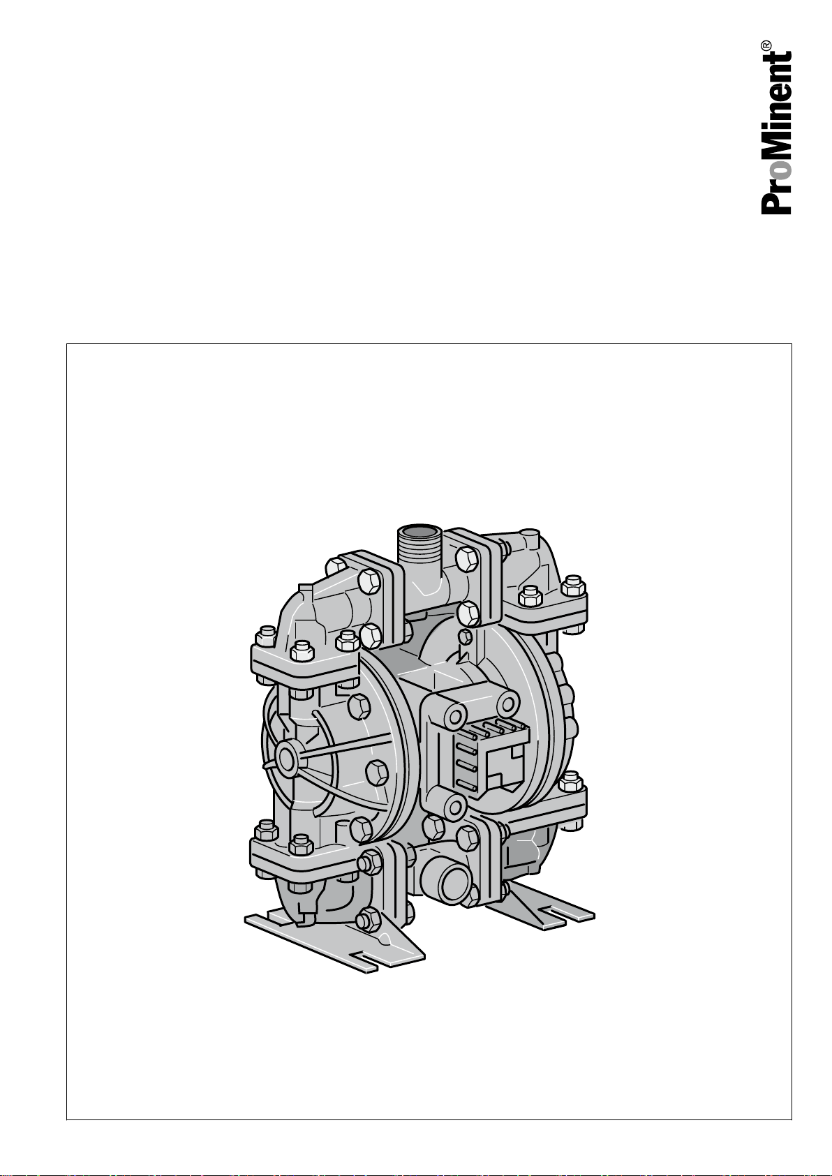
Duodos 10
Air-driven double diaphragm pump
EN
Please carefully read these operating instructions before use. · Do not discard.
The operator shall be liable for any damage caused by installation or operating errors.
The latest version of the operating instructions are available on our homepage.
Original Operating Instructions (2006/42/EC)Part number 985472 BA DUO 011 09/16 EN
Page 2
Supplemental instructions
General non-discriminatory approach
Supplementary information
In order to make it easier to read, this document uses the male
form in grammatical structures but with an implied neutral sense. It
is aimed equally at both men and women. We kindly ask female
readers for their understanding in this simplification of the text.
Please read the supplementary information in its entirety.
Information
This provides important information relating to the cor‐
rect operation of the unit or is intended to make your
work easier.
Warning information
Warning information includes detailed descriptions of the haz‐
ardous situation, see
tion’ on page 5
Ä Chapter 2.1 ‘Labelling of Warning Informa‐
.
The following symbols are used to highlight instructions, links, lists,
results and other elements in this document:
More symbols
Symbol Description
Action, step by step.
⇨ Outcome of an action.
Links to elements or sections of these instructions or other applicable documents.
n
[Button]
List without set order.
Display element (e.g. indicators).
Operating element (e.g. button, switch).
‘Display /GUI’
CODE
Screen elements (e.g. buttons, assignment of function keys).
Presentation of software elements and/or texts.
2
Page 3

Table of contents
Table of contents
1 Function and identification.................................................... 4
1.1 Function........................................................................ 4
1.2 Identification.................................................................. 4
2 Safety and Responsibility...................................................... 5
2.1 Labelling of Warning Information.................................. 5
2.2 Users' qualifications...................................................... 6
2.3 Intended use................................................................. 7
2.4 Duodos general safety notes........................................ 7
3 Transport and storage......................................................... 10
3.1 Transport.................................................................... 10
3.2 Storage....................................................................... 10
4 Assembly............................................................................ 11
4.1 Installation surroundings............................................. 11
4.1.1 Securing the double diaphragm pump..................... 12
4.2 Ambient conditions..................................................... 13
4.3 Layout of the suction side........................................... 13
4.4 Compressed air supply............................................... 14
5 Operation of the double diaphragm pump.......................... 15
6 Commissioning................................................................... 16
6.1 Checks prior to commissioning................................... 16
6.2 Priming........................................................................ 17
6.3 Interrupting operation.................................................. 17
7 Checking Tightening Torque Prior to Commissioning......... 18
8 Maintenance of the double diaphragm pump...................... 19
8.1 Troubleshooting.......................................................... 19
8.2 Air valve maintenance................................................ 20
8.3 Maintenance of the pilot valve.................................... 23
8.4 Maintenance of the ball valves................................... 24
8.5 Maintenance of the diaphragms................................. 25
9 Disposal of Used Parts....................................................... 27
10 Technical Drawing – Duodos 10......................................... 28
10.1 Exploded drawings and parts lists............................ 29
11 Spare Parts kits................................................................... 33
12 Technical data..................................................................... 34
12.1 Performance curves.................................................. 36
13 Declaration of Conformity................................................... 37
14 Index................................................................................... 38
3
Page 4

Function and identification
1 Function and identification
1.1 Function
The Duodos is an air-driven double diaphragm pump.
The Duodos is run-dry safe and self-priming.
The pump capacity of the double diaphragm pump can be con‐
trolled by changing the pressure in the air supply. The air control is
designed for oil-free operation. The Duodos is optimally suited to
the transport of liquid chemicals.
The Duodos double diaphragm pump transports liquids to a dis‐
charge lift of 70 m. As the pump capacity depends greatly on the
back pressure, the performance curve must always be observed.
At the same time, the differential pressure between the hydraulic
and pneumatic sides must not exceed 2 bar. Higher values reduce
the service life of the double diaphragm pump.
When selecting the double diaphragm pump you must check its
material compatibility. In addition, the density, viscosity, solids con‐
tent and temperature of the liquid being transported must be con‐
sidered.
Permissible values for the medium
Temperature of the medium
–
PP version: 5 ... 65 °C
–
PVDF version: -13 ... 93 °C
Viscosity of the medium max. 200 mPas
Solids content: none
1.2 Identification
Type Housing Diaphragm Feed rate l/h Order numbers
Duodos 10 PP
Duodos 10 PVDF
Santoprene
Teflon
®
®
0 ... 900 1010793
0 ... 900 1010797
4
Page 5
2 Safety and Responsibility
2.1 Labelling of Warning Information
Safety and Responsibility
Introduction
These operating instructions provide information on the technical
data and functions of the product. These operating instructions pro‐
vide detailed warning information and are provided as clear stepby-step instructions.
The warning information and notes are categorised according to
the following scheme. A number of different symbols are used to
denote different situations. The symbols shown here serve only as
examples.
DANGER!
Nature and source of the danger
Consequence: Fatal or very serious injuries.
Measure to be taken to avoid this danger.
Description of hazard
– Denotes an immediate threatening danger. If the
situation is disregarded, it will result in fatal or very
serious injuries.
WARNING!
Nature and source of the danger
Possible consequence: Fatal or very serious injuries.
Measure to be taken to avoid this danger.
– Denotes a possibly hazardous situation. If the sit‐
uation is disregarded, it could result in fatal or very
serious injuries.
CAUTION!
Nature and source of the danger
Possible consequence: Slight or minor injuries. Mate‐
rial damage.
Measure to be taken to avoid this danger.
– Denotes a possibly hazardous situation. If the sit‐
uation is disregarded, it could result in slight or
minor injuries. May also be used as a warning
about material damage.
NOTICE!
Nature and source of the danger
Damage to the product or its surroundings.
Measure to be taken to avoid this danger.
– Denotes a possibly damaging situation. If the situa‐
tion is disregarded, the product or an object in its
vicinity could be damaged.
5
Page 6

Safety and Responsibility
2.2 Users' qualifications
Type of information
Hints on use and additional information.
Source of the information. Additional measures.
–
Denotes hints on use and other useful information.
It does not indicate a hazardous or damaging sit‐
uation.
WARNING!
Danger of injury with inadequately qualified personnel!
The operator of the plant / device is responsible for
ensuring that the qualifications are fulfilled.
If inadequately qualified personnel work on the unit or
loiter in the hazard zone of the unit, this could result in
dangers that could cause serious injuries and material
damage.
– All work on the unit should therefore only be con‐
ducted by qualified personnel.
– Unqualified personnel should be kept away from
the hazard zone
Training Definition
Instructed personnel An instructed person is deemed to be a person who has been instructed and,
if required, trained in the tasks assigned to him/her and possible dangers that
could result from improper behaviour, as well as having been instructed in the
required protective equipment and protective measures.
Trained user A trained user is a person who fulfils the requirements made of an instructed
person and who has also received additional training specific to the system
from ProMinent or another authorised distribution partner.
Trained qualified per‐
sonnel
Electrician Electricians are deemed to be people, who are able to complete work on elec‐
Customer Service depart‐
ment
A qualified employee is deemed to be a person who is able to assess the
tasks assigned to him and recognize possible hazards based on his/her
training, knowledge and experience, as well as knowledge of pertinent regula‐
tions. The assessment of a person's technical training can also be based on
several years of work in the relevant field.
trical systems and recognize and avoid possible hazards independently based
on his/her technical training and experience, as well as knowledge of pertinent
standards and regulations.
Electricians should be specifically trained for the working environment in
which the are employed and know the relevant standards and regulations.
Electricians must comply with the provisions of the applicable statutory direc‐
tives on accident prevention.
Customer Service department refers to service technicians, who have
received proven training and have been authorised by ProMinent to work on
the system.
6
Page 7
2.3 Intended use
Safety and Responsibility
Note for the system operator
The pertinent accident prevention regulations, as well
as all other generally acknowledged safety regulations,
must be adhered to!
CAUTION!
Intended use
Possible consequences if the instructions are not
observed: Minor injuries and material damage
– The pump is intended for liquids transport
– The pump is not intended for the transport of gas‐
eous or solid media
– Only use the pump in accordance with the tech‐
nical data and specifications outlined in the oper‐
ating instructions.
– The pump is not designed for use in areas at risk
from explosion
– Only switch the device on if it has been properly
fastened to the ground or its holding fixture.
2.4 Duodos general safety notes
WARNING!
Danger from hazardous substances!
Possible consequence: Fatal or very serious injuries.
Please ensure when handling hazardous substances
that you have read the latest safety data sheets pro‐
vided by the manufacture of the hazardous substance.
The actions required are described in the safety data
sheet. Check the safety data sheet regularly and
replace, if necessary, as the hazard potential of a sub‐
stance can be re-evaluated at any time based on new
findings.
The system operator is responsible for ensuring that
these safety data sheets are available and that they
are kept up to date, as well as for producing an associ‐
ated hazard assessment for the workstations affected.
7
Page 8
Safety and Responsibility
WARNING!
Hazardous media / contamination of persons and
equipment
Possible consequence: Fatal or very serious injuries.
material damage
– Ensure the device is resistant to the media being
conveyed
– Always observe the safety data sheets for the
media to be conveyed. The system operator must
ensure that these safety data sheets are available
and that they are kept up-to-date
– The safety data sheets for the media being con‐
veyed are always decisive for initiating counter
measures in the event of leakage to the media
being conveyed
– Observe the general restrictions in relation to vis‐
cosity limits, chemical resistance and density
WARNING!
Service life of the diaphragm
Possible consequence: Fatal or very serious injuries
The service life of the diaphragm cannot be precisely
specified. For this reason, the possibility of fracture
and subsequent leakage of liquids must be taken into
account.
In addition, you must prevent particles from the defec‐
tive diaphragm reaching the media being conveyed.
This can be achieved e.g. by filtration, a hose rupture
alarm or other means suitable for the respective
process.
CAUTION!
Compressed air
Before working on the double diaphragm pump, close
the compressed air lines and vent the double dia‐
phragm pump.
Before undertaking any maintenance and repair work,
close off the compressed air supply, discharge the
compressed air and detach the air supply line from the
double diaphragm pump. The line to the discharge
side of the double diaphragm pump may be under
pressure and must likewise be vented.
CAUTION!
Hot surface
When conveying hot liquids, the pump can likewise
become hot. Hot surfaces may then be present on the
pump. Bear this in mind and take suitable measures to
reduce any hazards.
8
Page 9

Safety and Responsibility
Maximum pump sound pressure level 91 dB
Depending on the operating conditions, the maximum
sound pressure level of the device can reach 88 dB ±
3 dB. Bear this in mind and take suitable measures to
reduce any impact caused by this sound pressure
level. The type and implementation of suitable meas‐
ures depends on the local circumstances and is the
responsibility of the system operator.
Check the fastening elements are correctly seated.
Before commissioning the double diaphragm pump,
you must check that all fastening elements with sealing
rings are correctly seated. The seals may ‘creep’ , so
that the fastening elements come loose over time.
In the event of a diaphragm rupture
In the event of a diaphragm rupture, the pumped
medium can enter the air system of the double dia‐
phragm pump and from there into the atmosphere. If
the pumped medium is a dangerous, harmful or toxic
substance, the air outlet must be routed to a suitable
area where safe disposal is possible.
Operation in the open air and outdoors
–
Take suitable measures to protect the device from
environmental influences when operating outside
such as:
–
UV rays
–
Humidity
–
Frost, etc.
9
Page 10

Transport and storage
3 Transport and storage
n User qualification, transport and storage: trained user, see
Ä Chapter 2.2 ‘Users' qualifications’ on page 6
WARNING!
Danger from hazardous substances!
Possible consequence: Fatal or very serious injuries.
Please ensure when handling hazardous substances
that you have read the latest safety data sheets pro‐
vided by the manufacture of the hazardous substance.
The actions required are described in the safety data
sheet. Check the safety data sheet regularly and
replace, if necessary, as the hazard potential of a sub‐
stance can be re-evaluated at any time based on new
findings.
The system operator is responsible for ensuring that
these safety data sheets are available and that they
are kept up to date, as well as for producing an associ‐
ated hazard assessment for the workstations affected.
3.1 Transport
Transport
n The pump is protected by means of cardboard packaging
n The packaging materials can be recycled
n Consider the ambient conditions
3.2 Storage
The device must be completely drained before storage.
Permissible storage conditions:
All versions: + 5 °C ... 60 °C
All versions: < 95% relative air humidity (non-condensing)
Permissible operating conditions:
All versions: - 10 °C ... 40 °C
All versions: < 95% relative air humidity (non-condensing)
10
Page 11
4 Assembly
4.1 Installation surroundings
Assembly
n User qualification, installation: trained qualified personnel, see
Ä Chapter 2.2 ‘Users' qualifications’ on page 6
CAUTION!
Possible consequence: Slight or minor injuries. Mate‐
rial damage.
Observe the permissible ambient conditions.
Upright installation
Install the double diaphragm pump upright and plumb.
The valves of the double diaphragm pump operate
when loaded by gravity. The valve balls are pressed by
gravity into the valve seat and seal it off. Installation
outside the vertical axis impairs the function of the
valves.
Nominal width of the pipework
The threaded connectors must not reduce the nominal
width of the pipework or the double diaphragm pump.
The hydraulic connectors have internal and external
threads. Do not screw threaded fittings on to the
internal thread as this would lead to a reduction of the
nominal width.
Keep the suction line short and the number of pipe valves small.
Do not reduce the diameter of the suction line. If a rigid pipework
system is used, short flexible hose pieces should be inserted
between the double diaphragm pump and pipework to protect the
double diaphragm pump against vibration and tensile and com‐
pressive forces. The installation of a pulsation damper is recom‐
mended to reduce pulsations in the pumped medium.
11
Page 12
A1142
1.
2. 3. 4. 5. 6.
7.
8.
9.
10.
11. 12.
13.
14. 16. 17. 18.
19.
15.
Assembly
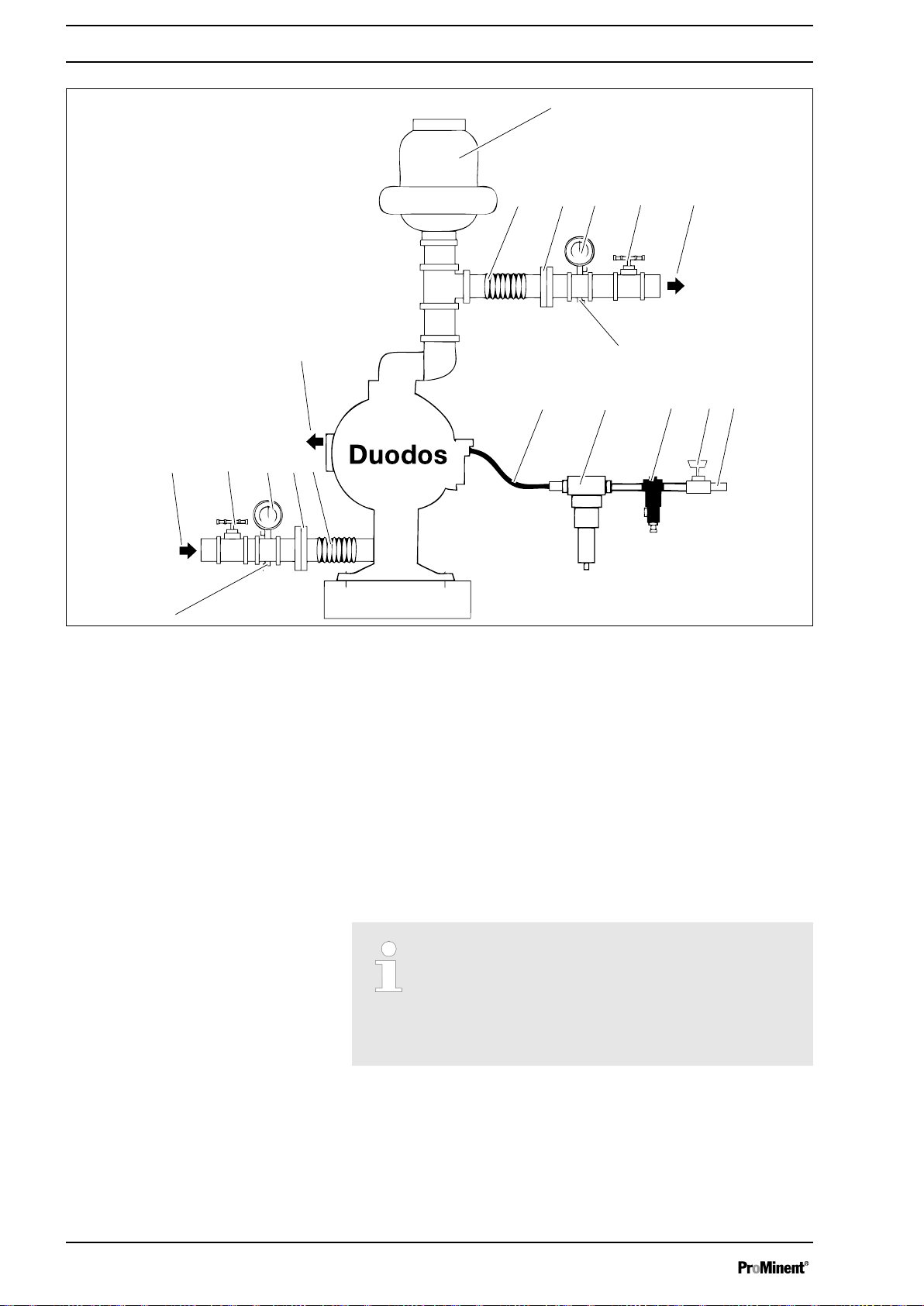
Fig. 1: Installation surroundings
1. Pulsation damper
2. Flexible connection
3. Pipe connection
4. Manometer
5. Shut-off valve
6. Discharge side
7. Outlet valve
8. Flexible connection
9. Filter/controller module
10. Air dryer (option)
4.1.1 Securing the double diaphragm pump
11. Shut-off valve
12. Compressed air connection
13. Outlet valve
14. Suction side
15. Shut-off valve
16. Manometer
17. Pipe connection
18. Flexible connection
19. Air outlet
Correct securing of the device
Only switch the device on if it has been properly fas‐
tened to the ground or its holding fixture. The system
operator is responsible for ensuring that the ground
and the fittings can hold the device safely and under all
operating conditions.
12
Page 13

4.2 Ambient conditions
4.3 Layout of the suction side
Assembly
NOTICE!
Ambient conditions
Possible consequence: Property damage and
increased wear and tear
Assembly is to be carried out in the following order. If
the pump has to be installed outdoors, then it is to be
equipped with protection against sunlight and weather
influences.
When positioning the pump, ensure that sufficient
room for access is provided for all types of mainte‐
nance work.
Nominal width of the pipework
The threaded connectors must not reduce the nominal
width of the pipework or the double diaphragm pump.
The hydraulic connectors have internal and external
threads. Do not screw threaded fittings on to the
internal thread as this would lead to a reduction of the
nominal width.
Dimensioning of the suction side
Layout the suction side with generous dimensions. The
supply of the double diaphragm pump with the liquid to
be pumped must be ensured under all load and oper‐
ating statutes. Ensure that the inside diameters of the
suction lines are generously sized.
To ensure a maximum service life of the diaphragm, the double
diaphragm pump should be installed as close as possible to the
pumped medium. If there is a positive priming pressure on the suc‐
tion side of more than 3.0 m water column, the fitting of a back
pressure valve in the air outlet of the double diaphragm pump is
recommended in order to protect the diaphragm. The minimum air
pressure to operate the double diaphragm pump is approximately 1
bar.
13
Page 14

Assembly
4.4 Compressed air supply
Compressed air supply
The double diaphragm pump must be connected to a
compressed air supply in accordance with the current
state of the art (ISO 8573-1). We require unoiled,
residual oil-free (residual oil from the compressors of
maximum 0.1 mg/m³ for HEES-liquids, bio-oils or max.
5mg/m³ permitted for mineral oils) and appropriately
dried compressed air (ISO 8573-1, class 4 with 3 °C
PDP).
Our recommendation is that the pressure dew point
must be at least 10 °C below the ambient temperature.
Suitable compressed air supply
The system operator is responsible for the provision of
a suitable compressed air supply. In doing so, observe
ISO 8573.
Lubrication of the air valves
Layout the compressed air supply with generous dimensions. Your
compressed air supply must be able to supply the double dia‐
phragm pump with sufficient compressed air at any time and under
all operating statutes. In this respect also consider the air con‐
sumption of other devices and machinery connected to the same
compressed air supply. Considerable pressure fluctuations can
occur in the compressed air supply when switching compressed air
consumers on and off.
The air pressure of the supplied air must not exceed 7 bar (100
psi). Connect the air inlet of the double diaphragm pump to a com‐
pressed air supply, which is designed to provide the required pump
capacity in terms of air quantity and pressure. To guarantee the
supply pressure remains within the specified values, a control
valve should be connected upstream of the double diaphragm
pump.
In there is a rigid air supply line insert a short piece of flexible hose
between the double diaphragm pump and the pipework.
The weight of the air supply line, control valve, and filters must not
weigh upon the air connection fitting of the double diaphragm
pump, rather it must be supported in a suitable manner. Otherwise
the double diaphragm pump can be damaged.
Based on their design, the air valve and the pilot valve do not
require any lubrication and indeed must not be lubricated.
Moisture in the air line
Water in the compressed air can lead to the exhaust air freezing or
the double diaphragm pump icing up. The possible consequences
are malfunctions or failure of the double diaphragm pump. It is rec‐
ommended that an air dryer is fitted. This extracts the water from
the compressed air and protects against icing up.
14
Page 15

Operation of the double diaphragm pump
5 Operation of the double diaphragm pump
n User qualification: operation instructed personnel, see
Ä Chapter 2.2 ‘Users' qualifications’ on page 6
The double diaphragm pump is fully integrated into the customer
provided system and is then controlled from this system. It is not
possible to operate the double diaphragm pump directly.
15
Page 16

Commissioning
6 Commissioning
n User qualification, commissioning: trained user, see
6.1 Checks prior to commissioning
Ä Chapter
2.2 ‘Users' qualifications’ on page 6
Check the fastening elements are correctly seated.
Before commissioning the double diaphragm pump,
you must check that all fastening elements with sealing
rings are correctly seated. The seals may ‘creep’ , so
that the fastening elements come loose over time.
WARNING!
Danger from hazardous substances!
Possible consequence: Fatal or very serious injuries.
Please ensure when handling hazardous substances
that you have read the latest safety data sheets pro‐
vided by the manufacture of the hazardous substance.
The actions required are described in the safety data
sheet. Check the safety data sheet regularly and
replace, if necessary, as the hazard potential of a sub‐
stance can be re-evaluated at any time based on new
findings.
The system operator is responsible for ensuring that
these safety data sheets are available and that they
are kept up to date, as well as for producing an associ‐
ated hazard assessment for the workstations affected.
The following checks are to be carried out:
n Ensure that the device has not been damaged during transpor‐
tation or storage. Immediately report any damage to the sup‐
plier
n Check that the air pressure is suitable for the device.
n Ensure that the device is suitable for the liquid to be conveyed
and that it will not be attacked.
n Make sure that the temperature of the liquid does not exceed
the recommended temperature range
n Install a manometer in the discharge line if the back pressure
value is unknown
n Under the operating conditions, check the values for flow, pres‐
sure, etc.
n Install a pressure relief valve in the discharge line in order to
protect the pump in the event that a valve is unintentionally
closed off or the line is blocked in another way.
16
Page 17

6.2 Priming
6.3 Interrupting operation
Commissioning
1. To start the double diaphragm pump, open the air value by
approximately 1/2 to 3/4 of a turn
2.
Cavitation
If opening of the air valve causes the stroke rate
of the double diaphragm pump to increase, but
not however the flow volume passing through the
double diaphragm pump, then cavitation is the
cause. Slightly turn back the air valve so that the
air consumption and feed rate of the double dia‐
phragm pump are set in an optimum ratio.
Once the double diaphragm pump is filled with water, open
the air valve further to set the required air flow.
WARNING!
Danger from hazardous substances!
Possible consequence: Fatal or very serious injuries.
Please ensure when handling hazardous substances
that you have read the latest safety data sheets pro‐
vided by the manufacture of the hazardous substance.
The actions required are described in the safety data
sheet. Check the safety data sheet regularly and
replace, if necessary, as the hazard potential of a sub‐
stance can be re-evaluated at any time based on new
findings.
The system operator is responsible for ensuring that
these safety data sheets are available and that they
are kept up to date, as well as for producing an associ‐
ated hazard assessment for the workstations affected.
Rinse through the double diaphragm pump after every use if liquids
are used which when stationary have a tendency to form deposits
or to solidify. This avoids damage to the double diaphragm pump.
Liquid residues remaining in the double diaphragm pump may dry
out and form deposits. When restarting the double diaphragm
pump, this can lead to problems at the diaphragms and the ball
valves. At temperatures below 0 °C the double diaphragm pump
must always be completely drained.
17
Page 18

A2249
3,4 Nm
2,2 Nm
2,2 Nm
2,2 Nm
2,2 Nm
I.
Checking Tightening Torque Prior to Commissioning
7 Checking Tightening Torque Prior to Commissioning
Lasting tightness
Check that the threaded connectors have the correct
torque during commissioning.
We also recommend checking these threaded connec‐
tors for correct torque at least once a year because the
pump material yields and the tightening torque is then
reduced.
Fig. 2: Checking tightening torque prior to commissioning.
1. Tighten all screws (37) to 2.2 Nm.
2. Tighten the screw (11) to 3.4 Nm.
3. Tighten the nut (25) at position I by instinct as there is no
torque specified for this nut.
18
Page 19

Maintenance of the double diaphragm pump
8 Maintenance of the double diaphragm pump
n User qualification, wait: instructed personnel, see
2.2 ‘Users' qualifications’ on page 6
WARNING!
Danger from hazardous substances!
Possible consequence: Fatal or very serious injuries.
Please ensure when handling hazardous substances
that you have read the latest safety data sheets pro‐
vided by the manufacture of the hazardous substance.
The actions required are described in the safety data
sheet. Check the safety data sheet regularly and
replace, if necessary, as the hazard potential of a sub‐
stance can be re-evaluated at any time based on new
findings.
The system operator is responsible for ensuring that
these safety data sheets are available and that they
are kept up to date, as well as for producing an associ‐
ated hazard assessment for the workstations affected.
Before all work
Before all work on the double diaphragm pump, dis‐
connect the double diaphragm pump from the com‐
pressed air supply and the feed and discharge lines,
vent and decontaminate. Always observe the safety
data sheet for the chemicals to be conveyed.
Ä Chapter
8.1 Troubleshooting
Possible symptoms
n Double diaphragm pump does not cycle
n Double diaphragm pump cycles, but does not pump
n Double diaphragm pump cycles, but insufficient feed rate
n Double diaphragm pump cycles irregularly
n Double diaphragm pump vibrates strongly
Cause: Measure:
Suction lift of the system too high For suction lifts above 6 metres, priming of the pump can in most
cases be induced by pre-filling the pump chambers
Too high priming pressure on the
suction side of the system
Back pressure of the medium
higher than the air pressure
Compressed air pressure higher
than the back pressure of the
medium
If there is a priming pressure of more than 3 metres water column, pro‐
vide a back pressure valve in the air outlet of the double diaphragm
pump
Increase the air inlet pressure to the double diaphragm pump
Adjust the feed air pressure according to the performance curve of the
double diaphragm pump. At high stroke rates, cavitation in the medium
may occur
Suction line of too small nominal
width
Observe the recommendations of the dimensioned drawing for the
cross-section of the suction line
19
Page 20

Maintenance of the double diaphragm pump
Cause: Measure:
Air line of too small nominal width Observe the recommendations for dimensioning of the air inlet line in
the operating instructions of the double diaphragm pump
Air distribution system of the
Dismantle and examine the air valve, pilot valve and control pins
double diaphragm pump
Rigid pipe connections at the
Use flexible connections and a pulsation damper
pump
Exhaust air silencer blocked Remove the silencer. Then clean or de-ice and refit.
Pumped medium in the exhaust
air silencer
Dismantle pump chambers and determine whether a diaphragm is
broken or a diaphragm flange is loose
Ball valve blocked Dismantle the liquid end of the double diaphragm pump and clear the
blockage
Ball valve or valve seat worn or
distorted
Check the ball valves and valve seats for wear and correct seating
Replace as necessary
Suction line blocked Clear blockage or check and clean suction line
Discharge line blocked Check for blockage. Valves in the discharge line may be closed
Pump chamber blocked Dismantle the liquid end and inspect the diaphragm chambers of the
double diaphragm pump
8.2 Air valve maintenance
To carry out maintenance on the air valve first discon‐
nect the compressed air supply, vent the double dia‐
phragm pump and remove the air supply line from the
double diaphragm pump.
20
Page 21

7.
6.
3.
3.
2.
10.
11.
9.
8.
1.
3.
7.
24.
23 .
20 .
13 .
14 .
15 .
10 .
16 .
6.
12.
21.
22.
A1137
Maintenance of the double diaphragm pump
Fig. 3: Air valve maintenance
Dismantle the air valve
Reassemble the air valve
1. Remove the 4 screws (11)
2. Remove the air valve housing (1)
3. Remove the seals (8 and 12).
Check the seals and replace as necessary.
ð
4. Using pliers, remove the two safety collars (7) of the air valve
and the two end stops (6)
Replace the O-rings (3) as necessary.
ð
5. Pull the piston (2) out of the control cylinder. Ensure that the
piston is not scratched or damaged
6. Clean the piston with a soft cloth
7. Check the piston for scratches and signs of wear
Replace the piston as necessary.
ð
8. Check whether the control cylinder (is one part of 2) is dirty
on the inside or scratched
Replace the control cylinder and piston (2) as necessary.
ð
9. Insert an end stop (6) with O-ring (3) and safety collar (7) in
the air valve housing (1)
10. Remove the new control cylinder and piston (2) from the
plastic bag and pull the piston out of the control cylinder
11. Push the six O-rings (3) on to the control cylinder and press
the O-rings into the recesses
12. Coat the O-rings thinly with grease prior to fitting the control
cylinder in the air valve housing
13. Align the slots in the control cylinder with the slots in the air
valve housing (1)
21
Page 22

Maintenance of the double diaphragm pump
14. Push the piston into the control cylinder up to the already
mounted end cover. Ensure this does not cause any
scratches.
15. Fit the second end stop complete with an O-ring
16. Fit the remaining safety collar
17. Now you can refit the air valve housing in the pump
18. Place the cover (9), the valve house seal (8), the air valve
housing (1), with the five rectangular recesses pointing
towards the cover, and the seal (12) with the four hexagon
head screws on the double diaphragm pump
19. Push the silencer (14) and the cover (15) on to the screws
20. Fit the washers (10) and the hexagon nuts (16) and tighten
the nuts to 3.4 Nm.
21. Switch the compressed air supply back on
ð
The double diaphragm pump is now ready for use.
22
Page 23

8.3 Maintenance of the pilot valve
7.
6.
3.
3.
2.
10.
11.
9.
8.
1.
3.
7.
24.
23 .
20 .
13 .
14 .
15 .
10 .
16 .
6.
12.
21.
22.
A1137
Maintenance of the double diaphragm pump
To carry out maintenance on the pilot valve first dis‐
connect the compressed air supply, vent the double
diaphragm pump and remove the air supply line from
the double diaphragm pump.
Fig. 4: Maintenance of the pilot valve
Dismantle the pilot valve
Reassemble the pilot valve
1. Remove both tensioning straps
2. Screw out the outer diaphragm flange, diaphragms and inner
diaphragm flange together in an anti-clockwise direction
3. To be able to remove the piston (23) of the pilot valve, you
must remove the O-ring (24) at one end of the piston
4. Press the piston out of the control cylinder and inspect the Orings (24) for damage and wear
Replace damaged O-rings
ð
5. To remove the control cylinder, remove the safety collar (22)
6. Examine the inside of the control cylinder (20) of the pilot
valve to determine if it is dirty or scratched or has any other
defects
If necessary replace the control cylinder (20)
ð
7. Lightly grease the six O-rings (21)
8. Push the control cylinder from the chamfered end of the hole
into the pump housing (13)
9. Secure the control cylinder using the safety collar (22).
10. Lightly grease the four inner O-rings of the piston (23)
11. Insert the piston (23) in the control cylinder
23
Page 24

Maintenance of the double diaphragm pump
12. Pull the remaining O-rings (24) onto the piston
13. Screw the outer diaphragm flange, diaphragms and inner dia‐
14. Fit both tensioning straps
8.4 Maintenance of the ball valves
phragm flange together in a clockwise direction on to the
piston rod
An inspection or maintenance is normally indicated if
upon starting the double diaphragm pump:
–
primes badly
–
provides less capacity
–
cycles irregularly
–
cycles, but does not pump
Before maintenance work
1. First close the suction line of the double diaphragm pump
2. Close the discharge line of the double diaphragm pump
3. Shut-off the compressed air supply
4. Vent the double diaphragm pump
5. Remove the air supply line from the double diaphragm pump
6. If necessary remove any liquid which may remain in the
double diaphragm pump
Now the double diaphragm pump can be removed for
ð
maintenance.
24
Page 25

39.
37.
34.
33.
37.
32.
38.
A1138
Maintenance of the double diaphragm pump
Ball valve assembly
After maintenance work
Fig. 5: Maintenance of the ball valves
1. Unscrew the screws (37) with which the connection fittings
are fastened to the pumping housings
2. Check the surfaces of the valve balls (34) and valve seats
(33) for wear and damage
Replace worn or damaged parts.
ð
3. Push the two seals (32) into the grooves of the valve seat
(33) and insert the valve seat in the pumping housing
4. Place the valve ball (34) on the valve seat and screw the pipe
elbows (39) to the pumping housing
1. Attach the air supply line to the double diaphragm pump
2. Open the compressed air supply
3. Open the discharge line of the double diaphragm pump
4. Open the suction line of the double diaphragm pump
Now the double diaphragm pump can pump again
ð
Check all connectors for leak-tightness
8.5 Maintenance of the diaphragms
Before maintenance work
1. First close the suction line of the double diaphragm pump
2. Close the discharge line of the double diaphragm pump
3. Shut-off the compressed air supply
4. Vent the double diaphragm pump
5. Remove the air supply line from the double diaphragm pump
25
Page 26

19.
18.
17.
25.
28.
43.
29.
26.
27.
30.
A1139
Maintenance of the double diaphragm pump
6. If necessary remove any liquid which may remain in the
Fig. 6: Maintenance of the diaphragms
1. Remove both tensioning straps (28)
2. Screw out the outer diaphragm flange (27), diaphragms (26)
Assembly the diaphragms in the
3.
reverse sequence
double diaphragm pump
Now the double diaphragm pump can be removed for
ð
maintenance.
and inner diaphragm flange (25) together in an anti-clockwise
direction
The inherent curvature of the diaphragms (26)
points outwards when fitting.
After maintenance work
Place the outer diaphragm flange (27) on the outside of the
diaphragms. When doing so, ensure that the side of the inner
diaphragm flange (25) with the larger radius points towards
the diaphragms.
4. Tighten the outer diaphragm flange to approx. 3 Nm. The dia‐
phragm must not turn freely with the diaphragm flange when
tightening.
1. Attach the air supply line to the double diaphragm pump
2. Open the compressed air supply
3. Open the discharge line of the double diaphragm pump
4. Open the suction line of the double diaphragm pump
Now the double diaphragm pump can pump again
ð
Check all connectors for leak-tightness
26
Page 27

9 Disposal of Used Parts
Disposal of Used Parts
n User qualification: instructed user, see
Ä Chapter 2.2 ‘Users'
qualifications’ on page 6
NOTICE!
Regulations governing the disposal of used parts
– Note the national regulations and legal standards
that currently apply in your country
The manufacturer will take back decontaminated used units pro‐
viding they are covered by adequate postage.
Decontaminate the unit before returning it for repair. To do so,
remove all traces of hazardous substances. Refer to the Material
Safety Data Sheet for your feed chemical.
A current Declaration of Decontamination is available to download
on the ProMinent website.
27
Page 28

0
1
66
78
33
0
4
1
9
7
5
3
3
1
7
6
198
167
87
2
3
19
2
3
8
7
1
179
I.
II.
III.
IV.
A1140
Technical Drawing – Duodos 10
10 Technical Drawing – Duodos 10
Fig. 7: Technical Drawing – Duodos 10
I. Suction connector
II. Discharge connector
III. Optional
IV. Compressed air connector
28
Page 29

10.1 Exploded drawings and parts lists
A1141
Exploded drawing – Duodos 10 PP
Technical Drawing – Duodos 10
Fig. 8: Exploded drawing – Duodos 10
Parts list Duodos 10 PP
Item Quan‐
tity
Part no. Reference
no.
Description Remark
1 1 1043218 095-077-551 Air valve housing Polypropylene, glass fibre-
reinforced
2 1 1043113 031-106-000 Control cylinder and piston, air
Subassembly
valve
3 8 1043183 560-101-360 O-ring Buna-N
6 2 1043233 165-074-551 End stops Polypropylene, glass fibre-
reinforced
7 2 1043124 675-051-115 Safety collar Stainless steel 302/304
8 1 1043247 360-085-360 Seal, air valve housing Buna-N
9 1 1043259 165-072-551 Cover, air inlet Polypropylene, glass fibre-
reinforced
10 8 1043105 901-037-115 Washer 1/4" Stainless steel 302/304
11 4 1043140 170-103-115 Hexagon head screw 1/4-20 5" Stainless steel 302/304
12 1 1043241 360-084-360 Seal, pump housing Buna-N
13 1 1043170 114-019-551 Pump housing Polypropylene, glass fibre-
reinforced
14 1 1043145 530-022-550 Silencer polyethylene
29
Page 30

Technical Drawing – Duodos 10
Item Quan‐
tity
Part no. Reference
no.
Description Remark
15 1 1043256 165-073-551 Cover, silencer Polypropylene, glass fibre-
reinforced
16 4 1043128 545-003-115 Hexagon head screw 1/4-20
Stainless steel 302/304
UNC
17 2 1043110 449-021-551 Packing gland insert Polypropylene, glass fibre-
reinforced
18 2 1043250 720-031-359 Seal, K-R Urethane
19 1 1043188 685-046-120 Diaphragm piston rod Stainless steel 416
20 1 1043222 755-038-000 Cylinder, pilot valve Subassembly
21 6 1043179 560-066-360 O-ring Buna-N
22 1 1043125 675-047-115 Safety collar, pilot valve cyl‐
Stainless steel 302/304
inder
23 1 1043221 775-038-000 Piston, pilot valve Subassembly
24 6 1043180 560-029-374 O-ring Nitrile
25 2 1043190 612-147-150 Inner diaphragm flange Aluminium
26 2 1043213 286-069-354 Diaphragm Santoprene
27 2 1043208 612-146-552 Outer diaphragm flange Polypropylene
28 2 1043119 200-057-115 Clip Stainless steel 302/304
29 2 1043224 100-002-115 Hammer screw Stainless steel 302/304
30 2 1043127 545-027-337 Hexagon head screw 1/4-28
Steel, chromed
UNF
31 2 1043167 196-145-552 Pumping housing Polypropylene
32 8 1043240 720-032-600 Valve seal PTFE
33 4 1043089 722-073-552 Valve seat Polypropylene
34 4 1043097 050-033-354 Valve ball Santoprene
35 2 1043148 312-095-552 Elbow, suction side Polypropylene
37 24 1043126 706-023-115 Hexagon head screw 10-32
Stainless steel 302/304
UNF x 1"
38 24 1043230 544-004-115 Flange nut 10-32 UNF Stainless steel 302/304
39 2 1043152 312-096-552 Elbow, discharge side Polypropylene
40 4 1043237 720-033-600 Distributor seal PTFE
41 1 1043076 518-127-552 Distributor fitting, horizontal Polypropylene
42 1 1043074 518-128-552 Distributor fitting, vertical Polypropylene
43 2 1043245 360-086-360 Seal, diaphragm Buna-N
55 8 1043126 706-023-115 Screw 10-32x1 Stainless steel 302/304
30
Page 31

Parts list Duodos 10 PVDF
Technical Drawing – Duodos 10
Item Quan‐
Part no. Reference no. Description Remark
tity
1 1 1043218 095-077-551 Air valve housing Polypropylene, glass fibre-
reinforced
2 1 1043113 031-106-000 Control cylinder and piston, air
Subassembly
valve
3 8 1043183 560-101-360 O-ring Buna-N
6 2 1043233 165-074-551 End stops Polypropylene, glass fibre-
reinforced
7 2 1043124 675-051-115 Safety collar Stainless steel 302/304
8 1 1043247 360-085-360 Seal, air valve housing Buna-N
9 1 1043259 165-072-551 Cover, air inlet Polypropylene, glass fibre-
reinforced
10 8 1043105 901-037-115 Washer 1/4" Stainless steel 302/304
11 4 1043140 170-103-115 Hexagon head screw 1/4-20 5" Stainless steel 302/304
12 1 1043241 360-084-360 Seal, pump housing Buna-N
13 1 1043170 114-019-551 Pump housing Polypropylene, glass fibre-
reinforced
14 1 1043145 530-022-550 Silencer polyethylene
15 1 1043256 165-073-551 Cover, silencer Polypropylene, glass fibre-
reinforced
16 4 1043128 545-003-115 Hexagon head screw 1/4-20
Stainless steel 302/304
UNC
17 2 1043110 449-021-551 Packing gland insert Polypropylene, glass fibre-
reinforced
18 2 1043250 720-031-359 Seal, K-R Urethane
19 1 1043188 685-046-120 Diaphragm piston rod Stainless steel 416
20 1 1043222 755-038-000 Cylinder, pilot valve Subassembly
21 6 1043179 560-066-360 O-ring Buna-N
22 1 1043125 675-047-115 Safety collar, pilot valve cyl‐
Stainless steel 302/304
inder
23 1 1043221 775-038-000 Piston, pilot valve Subassembly
24 6 1043180 560-029-374 O-ring Nitrile
25 2 1043190 612-147-150 Inner diaphragm flange Aluminium
26 2 1043215 286-070-600 Diaphragm PTFE
27 2 1043206 612-146-520 Outer diaphragm flange PVDF
28 2 1043119 200-057-115 Clip Stainless steel 302/304
29 2 1043224 100-002-115 Hammer screw Stainless steel 302/304
30 2 1043127 545-027-337 Hexagon head screw 1/4-28
Steel, chromed
UNF
31 2 1043163 196-145-520 Pumping housing PVDF
32 8 1043240 720-032-600 Valve seal PTFE
31
Page 32

Technical Drawing – Duodos 10
Item Quan‐
Part no. Reference no. Description Remark
tity
33 4 1043085 722-073-520 Valve seat PVDF
34 4 1043101 050-034-600 Valve ball PTFE
35 2 1043146 312-095-520 Elbow, suction side PVDF
37 24 1043126 706-023-115 Hexagon head screw 10-32
Stainless steel 302/304
UNF x 1"
38 24 1043230 544-004-115 Flange nut 10-32 UNF Stainless steel 302/304
39 2 1043150 312-096-520 Elbow, discharge side PVDF
40 4 1043237 720-033-600 Distributor seal PTFE
41 1 1043075 518-127-520 Distributor fitting, horizontal PVDF
42 1 1043063 518-128-520 Distributor fitting, vertical PVDF
43 2 1043245 360-086-360 Seal, diaphragm Buna-N
55 8 1043126 706-023-115 Screw 10-32x1 Stainless steel 302/304
32
Page 33

11 Spare Parts kits
Spare parts kit Part no.
Air drive for Duodos 10 1010810
Liquid end for Duodos 10 PP 1010801
Liquid end for Duodos 10 PVDF 1010806
Parts list spare parts kit - Duodos 10
Spare parts kit air drive - Duodos 10 (order no. 1010810):
Spare Parts kits
ItemQuan
tity
Part no. Reference
no.
Description Remark
2 1 1043113 031-106-000 Control cylinder and piston Subassembly
12 1 1043241 360-084-360 Seal, pump housing
8 1 1043247 360-085-360 Seal, air valve housing
3 8 1043183 560-101-360 O-ring
Buna-N
Buna-N
Buna-N
®
®
®
22 1 1043125 675-047-115 Safety collar, pilot valve cylinder Stainless steel 302/304
7 2 1043124 675-051-115 Safety collar Stainless steel 302/304
18 2 1043250 720-031-359 Seal, K-R Polyurethane
23 1 1043222 755-038-000 Piston, pilot valve Subassembly
20 1 1043221 775-038-000 Cylinder, pilot valve Subassembly
Spare parts kit liquid end for Duodos 10 PP (order no. 1010801):
ItemQua
ntity
34 4 1043101 050-033-354 Valve ball
26 2 1043213 286-069-354 Diaphragm
43 2 1043245 360-086-360 Seal, diaphragm
Part no. Reference
no.
Description Remark
Santoprene
Santoprene
Buna-N
®
®
®
32 8 1043240 720-032-600 Valve seal PTFE
40 4 1043237 720-033-600 Distributor seal PTFE
Spare parts kit liquid end for Duodos 10 PVDF (order no. 1010806):
ItemQua
Part no. Reference
ntity
Description Remark
no.
34 4 1043101 050-034-600 Valve ball PTFE
26 2 1043215 286-070-600 Diaphragm PTFE
43 2 1043245 360-086-360 Seal, diaphragm
Buna-N
32 8 1043240 720-032-600 Valve seal PTFE
40 4 1043237 720-033-600 Distributor seal PTFE
33
®
Page 34

Technical data
12 Technical data
Technical data – Duodos PP / PVDF
Order no. 1010793 1010797
Pump type Duodos 10 PP Duodos 10 PVDF
Capacity (max.) 900 l/h 900 l/h
Back pressure (max.) 70 m water column 70 m water column
Feed rate/stroke 0.04 l 0.04 l
Temperature of medium 5 ... 65 °C -13 ... 93 °C
Viscosity of medium max. 200 mPa·s max. 200 mPa·s
Suction lift dry 0.5 m 0.5 m
Suction lift moist 5.0 m 5.0 m
Sound pressure level Maximum 88 dB ± 3 dB Maximum 88 dB ± 3 dB
Suction connector "1/2"" NPT male
1/4"" NPT female"
Pressure connector "1/2"" NPT male
1/4"" NPT female"
Compressed air con‐
1/4" NPT female 1/4" NPT female
"1/2"" NPT male
1/4"" NPT female"
"1/2"" NPT male
1/4"" NPT female"
nector
Air consumption
0.5 ... 11 Nm3/h 0.5 ...11 Nm3/h
Max. air pressure 7 bar 7 bar
Minimum air pressure
1 bar 1 bar
approx.
Pump housing PP PVDF
Diaphragm
Valve balls
Santoprene
Santoprene
®
®
PTFE
PTFE
Valve seats PP PVDF
Seals PTFE PTFE
Pump housing Polypropylene, fibreglass-rein‐
Polypropylene, fibreglass-reinforced
forced
Assembly bracket PP PVDF
Weight 2 kg 2.5 kg
Dimensions L x W x H 178 x 140 x 198 mm 178 x 140 x 198 mm
34
Page 35

Technical data
Operating temperatures
Material Min. op. temperature Max. op. temperature
Santoprene
®
Thermoplastic elastomers produced in the injection moulding process without a mesh layer. Flexible with
high durability. Excellent abrasion hardness.
PTFE -37 °C 100 °C
Chemically inactive and effectively impermeable. Only a very few chemicals are know to react with Teflon®.
PVDF -13 °C 93 °C
Polypropylene 5 °C 65 °C
Repair tools
Tool Size Duodos 10
Spanner 3/8" 9.52 mm X
Spanner 7/16" 11.11 mm X
-23 °C 100 °C
Spanner 1/2" 12.7 mm X
Screw driver 7 mm 7.00 mm X
35
Page 36

A1160
Technical data
12.1 Performance curves
Performance curves
The performance curves are based on the pumping of
water at ambient temperature (approx. 20 °C).
Fig. 9: Performance curve of Duodos 10 / Maximum air consumption 11 m³/h
I. Delivery height (m water column) II. Pump capacity in l/h
36
Page 37

13 Declaration of Conformity
In accordance with DIRECTIVE 2006/42/EC OF THE EUROPEAN
PARLIAMENT AND OF THE COUNCIL, Appendix I, BASIC
HEALTH AND SAFETY REQUIREMENTS, section 1.7.4.2. C.
We,
n ProMinent GmbH
n Im Schuhmachergewann 5 - 11
n D - 69123 Heidelberg, Germany,
hereby declare that the product specified in the following, complies
with the relevant basic health and safety requirements of the EC
Directive, on the basis of its functional concept and design and in
the version distributed by us. Any modification to the product not
approved by us will invalidate this declaration.
Extract from the EC Declaration of Conformity
Designation of the product: Pneumatic double diaphragm pump
Product type: Duodos
Declaration of Conformity
Serial number: see nameplate on the device
Relevant EC directives: EC Machinery Directive (2006/42/EC)
Harmonised standards applied,
in particular:
Date: 01.03.2012
EN ISO 12100 / 2010
EN 809
The EC Declaration of Conformity is available to download on our
homepage.
37
Page 38

Index
14 Index
A
Action, step by step ........................2
Applied harmonised standards ..............37
C
Correct and proper use .....................7
Counter measures .........................8
D
Designation of the product .................37
G
General non-discriminatory approach ..........2
L
Links to elements or sections of these instruc‐
tions or other applicable documents ...........2
M
More symbols ............................2
N
Non-discriminatory approach ................2
O
Operation in the open air and outdoors .........8
P
Protection against sunlight .................13
Protection against the weather ..............13
R
Relevant EC directives ....................37
S
Safety data sheet ......................8, 10
Serial number ...........................37
U
Users' qualifications .......................6
W
Warning information .......................5
38
Page 39

39
Page 40

ProMinent GmbH
Im Schuhmachergewann 5 - 11
69123 Heidelberg, Germany
Telephone: +49 6221 842-0
Fax: +49 6221 842-419
Email: info@prominent.com
Internet: www.prominent.com
985472, 3, en_GB
© 2016
 Loading...