

ProMinent DULCO Trans 41/1000 PVDF, DULCO Trans 41/1000 PP, DULCO Trans 32/700 PVDF, DULCO Trans 32/700 PP Assembly And Operating Instructions Manual
Page 1
Assembly and operating instructions
A2670
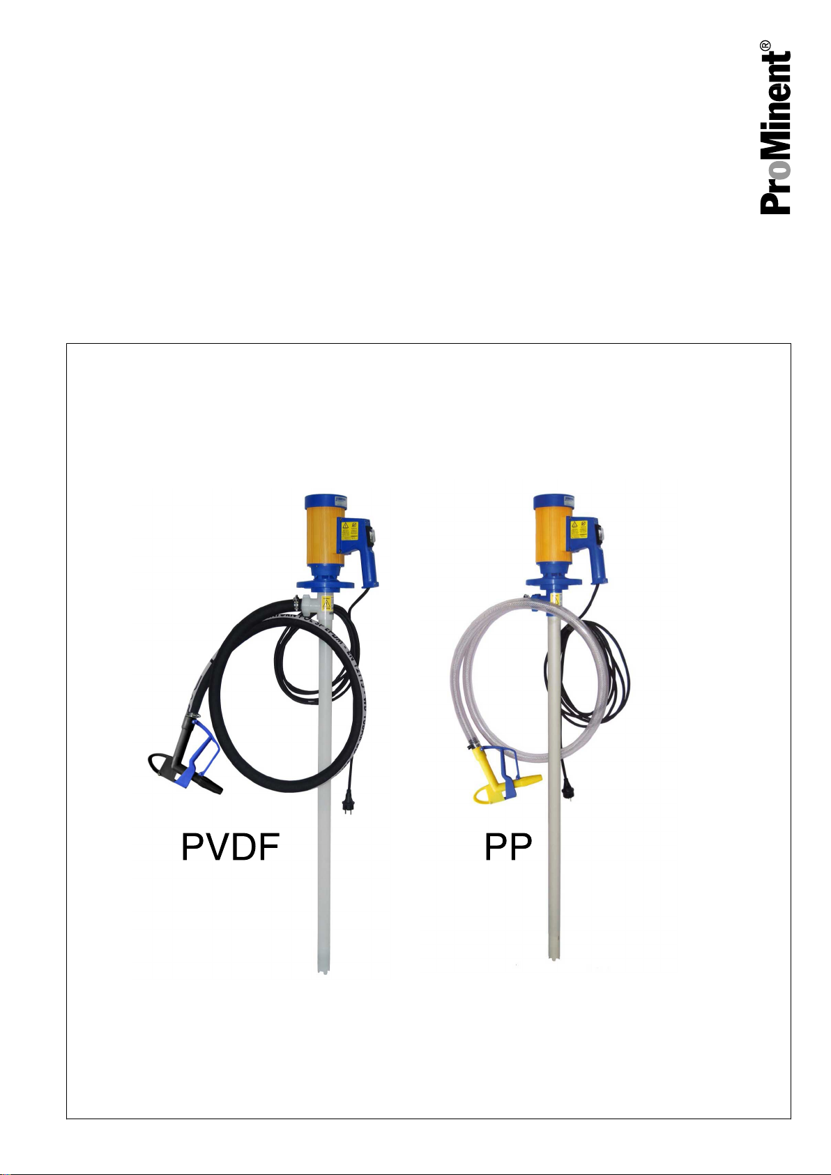
Barrel pump
DULCO®Trans 41/1000 PVDF or PP
EN
Please carefully read these operating instructions before use. · Do not discard.
The operator shall be liable for any damage caused by installation or operating errors.
The latest version of the operating instructions are available on our homepage.
Original Operating Instructions (2006/42/EG) / Target group: commercial use982028 BA DTR 005 01/19 EN
Page 2
Supplemental directives
General non-discriminatory approach
Supplementary information
In order to make it easier to read, this document uses the male
form in grammatical structures but with an implied neutral sense. It
is aimed equally at both men and women. We kindly ask female
readers for their understanding in this simplification of the text.
Please read the supplementary information in its entirety.
Information
This provides important information relating to the
correct operation of the unit or is intended to make
your work easier.
Warning information
Warning information includes detailed descriptions of the haz‐
ardous situation, see
tion’ on page 7
Ä Chapter 2.1 ‘Labelling of Warning Informa‐
.
The following symbols are used to highlight instructions, links, lists,
results and other elements in this document:
Tab. 1: More symbols
Symbol Description
Action, step by step.
⇨ Outcome of an action.
Links to elements or sections of these instructions or other applicable documents.
n
[Button]
List without set order.
Display element (e.g. indicators).
Operating element (e.g. button, switch).
‘Display /GUI’
CODE
Screen elements (e.g. buttons, assignment of function keys).
Presentation of software elements and/or texts.
2
Page 3

Table of contents
Table of contents
1 Function, resistance and scope of delivery........................... 4
2 Safety chapter....................................................................... 7
2.1 Labelling of Warning Information.................................. 7
2.2 User qualification.......................................................... 9
2.3 Intended Use................................................................ 9
2.4 Foreseeable Misuse................................................... 10
2.5 Safety.......................................................................... 10
2.5.1 Safety information for pump and motor................... 10
2.5.2 Safety information for the pump nozzle................... 12
2.6 Sound pressure level.................................................. 13
3 Storage and Transport........................................................ 14
3.1 Transport.................................................................... 14
3.2 Disposal of Packaging................................................ 14
4 Assembly and commissioning............................................. 15
4.1 Assembly of the pump................................................ 15
4.2 Motor description and overcurrent tripping................. 15
5 Operation............................................................................ 16
6 Cleaning after each use...................................................... 18
7 Repair, faults and spare parts............................................. 19
7.1 Checks/repairs............................................................ 19
7.2 Troubleshooting.......................................................... 21
7.3
Spare parts for the DULCO®Trans............................. 21
7.3.1
7.3.2
7.3.3 Spare parts for the motor......................................... 23
7.3.4 Spare parts for the pump......................................... 25
7.3.5 Spare parts for the pump nozzle.............................. 27
7.3.6 Accessories............................................................. 28
8 Disposal of used parts........................................................ 29
9 Technical data at a glance.................................................. 30
9.1 Technical data, PP version......................................... 30
9.2 Technical data, PVDF version.................................... 31
9.3 Performance diagram................................................. 32
9.4 Dimensional drawing with main dimensions............... 32
10 EC / EU Declaration of Conformity for Machinery............... 33
11 Index................................................................................... 34
Spare parts kit for DULCO®Trans 41/1000 PP........ 22
Spare parts kit for DULCO®Trans 41/1000 PVDF... 22
3
Page 4
Function, resistance and scope of delivery
1 Function, resistance and scope of delivery
Function
Device Max. pump capacity Max. delivery height Order number
DULCO®Trans 41/1000 PP
DULCO®Trans 41/1000 PVDF
* The pump capacity is also measured with water at 20 °C, a 1” pressure pipe and an oval wheel meter.
Chemical resistance
Barrel pumps are the ideal solution when liquids have to be moved.
The unit is used for bottling, draining and transferring non-flam‐
mable and non-explosive liquids from canisters, hobbocks, drums,
storage tanks and containers.
93 l/min* 11.0 m 1098491
93 l/ min* 11.0 m 1098493
The field of application of the unit depends on the
chemical resistance of the materials used.
Tab. 2: Wetted materials of the unit, PP version:
Component Material
External and internal pipe, pump nozzle PP
Drive shaft
Rotor PP
Metering hose PVC with woven inner layer
The resistance list, which is continually updated, can be found on the manufacturer’s homepage
www.prominent.com
Hastelloy® C
Tab. 3: Wetted materials of the unit, PVDF version:
Component Material
External and internal pipe, pump nozzle PVDF
Drive shaft
Rotor PVDF
Metering hose Cross-linked PE
The resistance list, which is continually updated, can be found on the manufacturer’s homepage
www.prominent.com
Hastelloy® C
4
Page 5
A2678
1
6
5
4
3
2
A2679
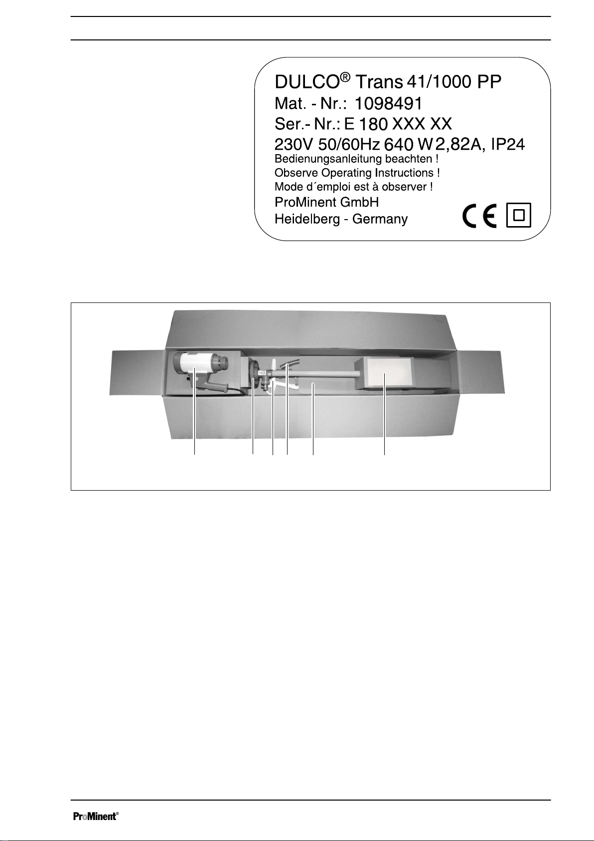
Nameplate
Scope of delivery
Function, resistance and scope of delivery
Fig. 1: Nameplate on the pump housing, PP version.
Fig. 2: A2679
1 Barrel pump motor
2 Pump
3 Pump nozzle assembled on the metering hose
4 Metering hose
5 Packaging
6 Assembly and operating instructions
5
Page 6
1 2
3
A2681
Function, resistance and scope of delivery
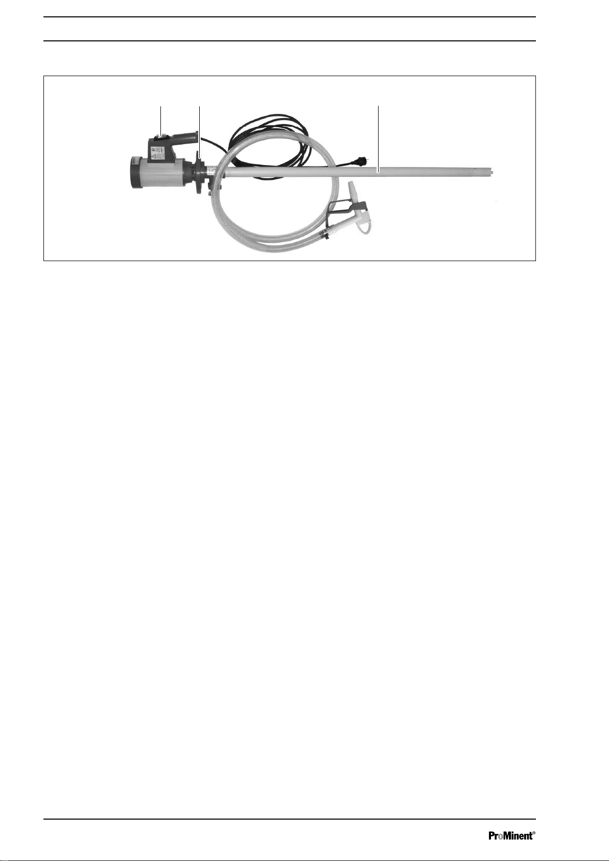
Overview of the key components
Fig. 3: Overview of the key components, PP version.
1 On/off switch.
2 Connecting nut.
3 Suction tube.
6
Page 7
2 Safety chapter
2.1 Labelling of Warning Information
Safety chapter
Introduction
These operating instructions provide information on the technical
data and functions of the product. These operating instructions pro‐
vide detailed warning information and are provided as clear stepby-step instructions.
The warning information and notes are categorised according to
the following scheme. A number of different symbols are used to
denote different situations. The symbols shown here serve only as
examples.
DANGER!
Nature and source of the danger
Consequence: Fatal or very serious injuries.
Measure to be taken to avoid this danger.
Description of hazard
– Denotes an immediate threatening danger. If
the situation is disregarded, it will result in fatal
or very serious injuries.
WARNING!
Nature and source of the danger
Possible consequence: Fatal or very serious inju‐
ries.
Measure to be taken to avoid this danger.
– Denotes a possibly hazardous situation. If the
situation is disregarded, it could result in fatal
or very serious injuries.
CAUTION!
Nature and source of the danger
Possible consequence: Slight or minor injuries.
Material damage.
Measure to be taken to avoid this danger.
– Denotes a possibly hazardous situation. If the
situation is disregarded, it could result in slight
or minor injuries. May also be used as a
warning about material damage.
NOTICE!
Nature and source of the danger
Damage to the product or its surroundings.
Measure to be taken to avoid this danger.
– Denotes a possibly damaging situation. If the
situation is disregarded, the product or an
object in its vicinity could be damaged.
7
Page 8

Safety chapter
Type of information
Hints on use and additional information.
Source of the information. Additional measures.
–
Denotes hints on use and other useful informa‐
tion. It does not indicate a hazardous or dam‐
aging situation.
8
Page 9

2.2 User qualification
Safety chapter
WARNING!
Danger of injury with inadequately qualified per‐
sonnel
The operator of the system / equipment is respon‐
sible for ensuring that the qualifications are ful‐
filled.
If inadequately qualified personnel work on the unit
or loiter in the hazard zone of the unit, this could
result in dangers that could cause serious injuries
and material damage.
– All work on the unit should therefore only be
conducted by qualified personnel.
– Unqualified personnel should be kept away
from the hazard zone.
The pertinent accident prevention regulations, as
well as all other generally acknowledged safety
regulations, must be adhered to.
Training Definition
Instructed personnel An instructed person is deemed to be a person who has been instructed and,
if required, trained in the tasks assigned to him and possible dangers that
could result from improper behaviour, as well as having been instructed in the
required protective equipment and protective measures.
Trained user A trained user is a person who fulfils the requirements made of an instructed
person and who has also received additional training specific to the system
from the manufacturer or another authorised distribution partner.
Trained, qualified per‐
sonnel
Electrical technician An electrical technician is able to complete work on electrical systems and rec‐
A trained, qualified employee is deemed to be a person who is able to assess
the tasks assigned to him and recognize possible hazards based on his
training, knowledge and experience, as well as knowledge of pertinent regula‐
tions. A trained, qualified employee must be able to perform the tasks
assigned to him independently with the assistance of drawing documentation
and parts lists. The assessment of a person's technical training can also be
based on several years of work in the relevant field.
ognise and avoid possible dangers independently based on his technical
training and experience as well as knowledge of pertinent standards and regu‐
lations. An electrical technician must be able to perform the tasks assigned to
him independently with the assistance of drawing documentation, parts lists,
terminal and circuit diagrams. The electrical technician must be specifically
trained for the working environment in which the electrical technician is
employed and be conversant with the relevant standards and regulations.
Service The Service department refers to service technicians, who have received
proven training and have been authorised by the manufacturer to work on the
system.
2.3 Intended Use
n The barrel pump is used for the fast and safe drainage or
transfer of storage tanks, drums and container.
n Depending on its design, the barrel pump can pump non-flam‐
mable liquids of all kinds.
9
Page 10

Safety chapter
2.4 Foreseeable Misuse
n The collector motor is used to drive the barrel pump in areas
not at risk of explosion and is used for non-flammable liquids.
n The pump nozzle is used for the bottling of liquids.
n Barrel pump, motor and pump nozzle are suitable for protected
use indoors and may not be exposed to weathering.
n The barrel pump, motor and pump nozzle are intended for
commercial use.
n The barrel pump and its accessories are not intended to be
used by untrained people and by people with restricted phys‐
ical, sensory or mental capabilities.
n Children should be supervised to ensure that they do not play
with the unit.
n The use of the pump nozzle is not permitted in petrol filling sta‐
tions (TRBF40).
n The pumping of flammable liquids is not permitted.
n Operation in areas at risk of explosion is not permitted.
2.5 Safety
This chapter gives an overview of all the important safety aspects
for the protection of individuals as well as for safe and fault-free
operation of the product. Other task-specific warning information
can be found in the individual action sequences.
The following chapters describe the residual risks that use of this
unit presents even when used as intended. Please refer to the
safety information listed here and comply with the warning informa‐
tion in the later chapters of these instructions to reduce these risks
of personal injury and material damage and avoid hazardous situa‐
tions.
2.5.1 Safety information for pump and motor
WARNING!
Danger from hazardous substances!
Possible consequence: Fatal or very serious inju‐
ries.
Please ensure when handling hazardous sub‐
stances that you have read the latest safety data
sheets provided by the manufacture of the haz‐
ardous substance. The actions required are
described in the safety data sheet. Check the
safety data sheet regularly and replace, if neces‐
sary, as the hazard potential of a substance can be
re-evaluated at any time based on new findings.
The system operator is responsible for ensuring
that these safety data sheets are available and that
they are kept up to date, as well as for producing
an associated hazard assessment for the worksta‐
tions affected.
10
Page 11

Safety chapter
Non-observance of the safety information
Non-observance of the safety information can lead
to damage to people and the environment and also
result in damage to the motor and pump.
n In the event of an emergency, disconnect from the mains
power supply.
n The motor is not explosion-protected.
n Do not leave the pump operating unsupervised.
n Do not use the pump in areas at risk from explosion.
n Never pump flammable liquids.
n Only use the pump for its intended purpose, see
Ä Chapter 2.3
‘Intended Use’ on page 9
n The pump is operated vertically.
n Set up the pump so that it cannot fall into the storage tank.
n Regularly check the pump and hose for operational safety.
n Regularly check the motor in accordance with statutory/
country-specific regulations and accident prevention regula‐
tions, in Germany such as in accordance with BGV A3.
n Secure the motor against accidental start-up. The pump can
start up as soon as the mains plug has been inserted.
n Before plugging in the mains plug, turn the On/Off switch to "0".
n The motor does not restart automatically following power
failure.
n Only immerse the pump in the liquid as far as the pressure
nozzle.
n Only allow the pump to stand in the liquid while it is pumping.
n Use the pump up to a maximum liquid temperature of 50 °C(PP
version) or a maximum liquid temperature of 90 °C (PVDF ver‐
sion).
n Ambient temperature: + 1 °C ... + 40 °C.
n Note any escaping air and displace volume when immersing
the pump in the water. Immerse the pump carefully and slowly.
n Use a spray guard with open drums or storage tanks.
n Remove any spilled liquid and dispose of it in an environmen‐
tally-friendly manner, referring to the material safety data
sheets issued by the manufacturer of the hazardous material.
n Note any internal instructions.
n Wear protective clothing, referring to the material safety data
sheets issued by the manufacturer of the hazardous material.
n Do not expose the pump to weathering.
n Clean the pump after each use, referring to the material safety
data sheets issued by the manufacturer of the hazardous
material.
n Do not store the pump in aggressive fumes.
11
Page 12

Safety chapter
2.5.2 Safety information for the pump nozzle
WARNING!
Danger from hazardous substances!
Possible consequence: Fatal or very serious inju‐
ries.
Please ensure when handling hazardous sub‐
stances that you have read the latest safety data
sheets provided by the manufacture of the haz‐
ardous substance. The actions required are
described in the safety data sheet. Check the
safety data sheet regularly and replace, if neces‐
sary, as the hazard potential of a substance can be
re-evaluated at any time based on new findings.
The system operator is responsible for ensuring
that these safety data sheets are available and that
they are kept up to date, as well as for producing
an associated hazard assessment for the worksta‐
tions affected.
Non-observance of the safety information
Non-observance of the safety information can lead
to damage to people and the environment and also
result in damage to the pump nozzle.
n Only pump clean liquids.
n When using, note the maximum operating pressure of 2 bar at
50 °C (PP design) or 2 bar at 60 °C (PVDF design). The pump
nozzle can bounce back.
n When filling into a storage tank, make sure that no overpres‐
sure can build up in this storage tank. Danger from spraying
liquids.
n Do not fill up too quickly to prevent the liquids from splashing
out of the storage tank.
n Only bend the hose slightly to prevent too high mechanical
stresses being exerted on the pump nozzle
n Only fill up using the pump nozzle under supervision, as the
nozzle does not automatically shut off.
n Check during commissioning whether the manual lever returns
automatically into its starting position.
n Use visual controls to regularly monitor the external condition
of the pump nozzle.
n Allow the pump nozzle to drain at the end of the filling process.
n Regularly check to make sure that the hose clips are fixed
securely.
n Remove any spilled liquid and dispose of it in an environmen‐
tally-friendly manner, referring to the material safety data
sheets issued by the manufacturer of the hazardous material.
n Note any internal instructions.
n Wear protective clothing, referring to the material safety data
sheets issued by the manufacturer of the hazardous material.
n Do not expose the pump nozzle to weathering.
n Clean the pump nozzle after each use, referring to the material
safety data sheets issued by the manufacturer of the haz‐
ardous material.
n Do not store the pump nozzle in aggressive fumes.
12
Page 13

2.6 Sound pressure level
Safety chapter
The sound pressure level is < 70 dB (A). This value was measured
on the manufacturer's test stand.
13
Page 14

Storage and Transport
3 Storage and Transport
3.1 Transport
3.2 Disposal of Packaging
n User qualification: instructed user, see
Ä Chapter 2.2 ‘User
qualification’ on page 9
Environmental conditions for storage and transport:
n Permissible ambient temperature: +1 °C ... +40 °C.
n Humidity: maximum 90 % relative air humidity, non-con‐
densing.
n Other: No dust, no direct sunlight.
The sensor should be transported in its original packaging and in
compliance with the permissible environmental conditions. No fur‐
ther special conditions have to be observed in relation to transport.
Packaging material
Dispose of packaging material in an environmen‐
tally responsible way. All packaging components
carry the corresponding recycling code .
14
Page 15

4 Assembly and commissioning
6
2
5
4
3
1
A2682
Assembly and commissioning
4.1 Assembly of the pump
n User qualification: instructed user,
cation’ on page 9
Ä Chapter 2.2 ‘User qualifi‐
Fig. 4: Assembly.
1. Use the connecting nut (3) to connect the pump (2) and the
2. Place the hose (4) (PVC = transparent, PE = black) on the
4.2 Motor description and overcurrent tripping
Inner-ventilated universal motor with overcurrent switch and zero
voltage trigger.
Repeated overloading can damage the motor. Overloading can be
caused by high-viscosity liquids or liquids with a higher density
than water.
Overcurrent trip:
n The motor switches off if the maximum current is exceeded.
motor (1).
hose plug (6) of the pump and use the hose clamp (5) to fix
the hose in place.
If the motor switches off due to overloading, reduce the vis‐
cosity and/or the density of the liquid.
You can immediately switch on the motor again by actuating
the On/Off switch.
15
Page 16

Operation
5 Operation
n User qualification: instructed user,
cation’ on page 9
WARNING!
Electrical voltage
Possible consequence: Fatal or very serious inju‐
ries.
– Before using, check the mains connection
cable for damage.
– Keep the mains connection cable away from
solvents.
WARNING!
Danger from hazardous substances!
Possible consequence: Fatal or very serious inju‐
ries.
Please ensure when handling hazardous sub‐
stances that you have read the latest safety data
sheets provided by the manufacture of the haz‐
ardous substance. The actions required are
described in the safety data sheet. Check the
safety data sheet regularly and replace, if neces‐
sary, as the hazard potential of a substance can be
re-evaluated at any time based on new findings.
The system operator is responsible for ensuring
that these safety data sheets are available and that
they are kept up to date, as well as for producing
an associated hazard assessment for the worksta‐
tions affected.
Ä Chapter 2.2 ‘User qualifi‐
Threaded connector (union nut)
–
Only operate the pump when the threaded con‐
nector (union nut) between the hose and pump
is manually tightened, see Ä Chapter 4
‘Assembly and commissioning’ on page 15.
–
Only switch on the motor if the pump's suction
pipe is in the liquid.
16
Page 17

2
1
A2683
Operation
Fig. 5: Operating the pump
1. Fix the barrel threaded connector (2) to the barrel. Insert the
pump into the liquid.
2. Check whether the manual lever of the pump nozzle returns
automatically to its starting position.
Never switch the pump on should this not be the case, as
ð
the pumping process could not therefore be regulated.
3. Compare the operating voltage observed with the data on the
nameplate.
4. Before plugging in the mains plug, turn the On/Off switch (1)
to "0".
5. Insert the mains plug.
The pump is now ready for operation.
ð
6. Use the On/Off switch to switch on the pump.
7. Press the pump nozzle's manual lever to pump the medium.
Measures after use
Drain the pump, hose and fittings after each use.
Allow the pump nozzle to drain in a controlled
manner after filling, as there can still be liquid in
the outlet tube, which would otherwise flow out in
an uncontrolled manner.
17
Page 18

A2684
Cleaning after each use
6 Cleaning after each use
Cleaning using a suitable cleaning
agent
n User qualification: instructed user, see
Ä Chapter 2.2 ‘User
qualification’ on page 9
WARNING!
Change of medium = Clean the pump
Hazard from the chemical incompatibility of the
media.
Possible consequence: Health risk and/or damage
to the pump and/or medium.
Remedy: Always thoroughly clean the pump when
the medium is changed. If you do not clean the
pump, it can lead to incompatibility between the
medium and pump or old medium and new
medium. Refer to the material safety data sheet on
the feed chemical.
Regular cleaning of the pump increases its service life and main‐
tains the performance of the pump.
1. Note the resistance of the pump and the hose to the cleaning
agent, referring to the reference list.
2. Use a suitable cleaning agent to rinse the pump, referring to
the material safety data sheet for the medium. Never use
flammable or explosive liquids.
Fig. 6: Lip (arrow) of the outlet nozzle.
3. Only immerse the pump in the cleaning agent as far as the lip
(arrow) of the outlet nozzle and never immerse the pump
fully.
4. Rinse the pump until the pump is clean.
The pump is now ready for further use, also with a dif‐
ð
ferent medium.
18
Page 19

7 Repair, faults and spare parts
4
3
2
1
A2669
7.1 Checks/repairs
Repair, faults and spare parts
Replacing the hose connection or
seal:
n User qualification: trained user,
tion’ on page 9
–
Regularly check the pump in accordance with
statutory/country-specific regulations and acci‐
dent prevention regulations (in Germany
such as in accordance with BGV A3).
It is essential that all faulty parts are replaced.
Preferably use genuine spare parts.
Ä Chapter 2.2 ‘User qualifica‐
Fig. 7: Components of the pump nozzle (PP = yellow and Blue,
PVDF = Black).
1. Housing.
2. Hose connection.
3. Protective mounting bracket.
4. Manual lever.
19
Page 20

A2671
Repair, faults and spare parts
Fig. 8: Components of the pump nozzle (PP = yellow and Blue, PVDF = Black).
1. Disconnect the pump from the mains power supply.
2. Allow the hose and pump nozzle to run empty.
3. Clean the pump.
Please proceed as follows to replace
the seals of the pump nozzle.
4. Remove the three grooved pins (5, 6 and 7) by pushing them
out using a small pin. The stainless steel pin is wider at one
side and can therefore only be removed in the direction of the
wider end
5. Then first remove the bracket (14), the manual lever (13) and
then the hose plug (12) on which the first (11) of a total of
three seals is located.
6. Then block the hexagonal opening at the rear end of the
valve rod (10) by inserting a long Allen key (size 8) into the
nozzle body from the rear side of the pump nozzle on which
you have removed the hose plug and blocking the hexagonal
opening.
7.
A compression spring (2) sits behind the
domed nut. When removing the domed nut,
make sure that you are not injured by the
spring when removing it as it is pressurised.
20
Page 21

7.2 Troubleshooting
Repair, faults and spare parts
Whilst holding the Allen key firmly with one hand, remove the
domed nut (1) from the other side with a size 10 socket.
8. A seal mount (3) is located behind the spring at the rear end
of which is located the second seal (4).
9. After removing the domed nut, the spring and the seal mount
with the second seal, you can push out the valve rod (10)
from this side towards the hose connection already removed
and replace the third seal (9).
10. Clean and check all components.
11. Replace all faulty or defective parts.
12. Finally fit the pump nozzle in the reverse order to that already
described and test the leak-tightness of the pump nozzle at
the end of a water line with 3 ... 4 bar pressure.
The pump nozzle is ready for use again.
ð
n User qualification: trained user, see
Ä Chapter 2.2 ‘User quali‐
fication’ on page 9
Fault Cause Solution
Manual lever on pump
nozzle sticking.
Pump starts but does not
pump.
Please contact Service with all other faults. For contact data see the Legal Notices.
Check on the manufacturer's website www.prominent.com whether a more recent version of the operating
instructions is available, as further remedies may have been developed in the meantime.
7.3
Spare parts for the DULCO®Trans
Joint stuck. Dismantle the pump nozzle, clean it and
replace any faulty components if neces‐
sary.
Maximum delivery height and/or
viscosity/density exceeded.
Inner tube blocked. Check and possibly clean inner tube.
Couplings, rotor faulty. Check the couplings and rotor and
n User qualification: Service, see
tion’ on page 9
Spare parts should only be ordered and fitted through Service.
Adjust the delivery height and/or viscosity.
replace if necessary.
Ä Chapter 2.2 ‘User qualifica‐
.
21
Page 22

Repair, faults and spare parts
7.3.1
Spare parts kit for DULCO®Trans 41/1000 PP
Tab. 4: Spare parts kit (order number 1098500) for DULCO®Trans 41/1000 PP, parts list
Pos. Description Material Quantity Order no.
16 a Carbon brushes Carbon 2 8080
21 a Motor coupling PA 1 8333
1 b V-seal PTFE 1 4000
2 b Pump factory coupling PA 1 1004
5 b Bearing unit Steel 1 1038
10 b Pump housing with PTFE bearing PP/PTFE 1 1524
12 b Rotor PP 1 1608
13 b Pump foot PP 1 1609
7.3.2
Spare parts kit for DULCO®Trans 41/1000 PVDF
Tab. 5: Spare parts kit (order number 1098498) for DULCO®Trans 41/1000 PVDF, parts list
Pos. Description Material Quantity Order no.
16 a Carbon brushes Carbon 2 8080
21 a Motor coupling PA 1 8333
1 b V-seal PTFE 1 4000
2 b Pump factory coupling PA 1 1004
5 b Bearing unit Steel 1 1038
10 b Pump housing with PTFE bearing PVDF/PTFE 1 4607
12 b Rotor PVDF 1 4608
13 b Pump foot PVDF 1 4609
22
Page 23

7.3.3 Spare parts for the motor
A2685
Repair, faults and spare parts
Fig. 9: Spare parts drawing for the motor.
23
Page 24

Repair, faults and spare parts
Tab. 6: Spare parts list for the motor
Position Description Quantity Order number
1a Lower part of handle 1 8001
2a Screw 2 8015
3a Screw 2 8016
4a Screw 4 8017
5a Motor cover 1 8026
6a Screw 8 8035
7a Handle cover 1 8037
8a Switch frame 1 8038
9a 5 m cable with earthed plug 1 8039
10a Screw 1 8045
11a Tension relief clamp 1 8046
12a Screw 2 8047
13a Spark interference filter 1 8056
14a Impeller 1 8070
15a Switch cover, transparent 1 8073
16a Carbon brush 2 8080
17a M5x110 screw 2 8081
18a Motor housing 1 8082
19a Lower bearing label 1 8083
20a Motor package 230 V, 50 Hz 1 8180
21a Motor coupling 1 8333
22a Switch 230 V, 3.5 A, 50 Hz with USP 1 8708
24
Page 25

7.3.4 Spare parts for the pump
A2686
Repair, faults and spare parts
Fig. 10: Spare parts drawing for the pump.
25
Page 26

Repair, faults and spare parts
Tab. 7: Spare parts list for the pump (PP design)
Position Description Quantity Order number Materials
1b V-seal 1 4000 PTFE
2b Coupling 1 1004 PA
3b
Drive shaft, Hastelloy
©
1 1006
Hastelloy
4b Outlet piece 1 1028 PP
5b Bearing unit (assembled) 1 1038 Steel
6b Hose plug DN 19 1 1051 PP
7b Wing nut 1 1106 PP
8b Retainer 1 1508 Spring steel
9b Teflon hose 1 1514 PTFE
©
10b Pump housing with PTFE
1 1524 PP, PTFE
bearing
11b Inner tube 1 1601 PP
12b Rotor 1 1608 PP
13b Pump foot 1 1609 PP
14b Outer tube 1 1611 PP
15b Manual adjustment wheel 1 1842 PP
Tab. 8: Spare parts list for the pump (PVDF version)
Position Description Quantity Order number Materials
1b V-seal 1 4000 PTFE
2b Coupling 1 1004 PA
3b
Drive shaft, Hastelloy
©
1 1006
Hastelloy
4b Outlet piece 1 4028 PVDF
5b Bearing unit (assembled) 1 1038 Steel
6b Hose plug DN 19 1 4051 PVDF
©
7b Wing nut 1 4106 PVDF
8b Retainer 1 1508 Spring steel
9b Teflon hose 1 1514 PTFE
10b Pump housing with PTFE
1 4607 PVDF, PTFE
bearing
11b Inner tube 1 4601 PVDF
12b Rotor 1 4608 PVDF
13b Pump foot 1 4609 PVDF
14b Outer tube 1 4591 PVDF
15b Manual adjustment wheel 1 1842 PP
26
Page 27

7.3.5 Spare parts for the pump nozzle
A2674
Repair, faults and spare parts
Fig. 11: Spare parts drawing for the pump nozzle.
Tab. 9: Spare parts list for the pump nozzle (PP design)
Position Description Quantity Order number Materials
1c Domed nut 1 1135 PP
2c Compression spring 1 1136 Stainless steel
3c Seal mount 1 1137 PP
4c O-ring 1 1138 FKM
5c Distance pin Ø 5x40 1 1141 Stainless steel
6c Distance pin Ø 5x25 1 1142 Stainless steel
7c Distance pin Ø 4x25 1 1143 Stainless steel
8c Housing 1 1144 PP
9c O-ring 1 1145 FKM
10c Valve rod 1 1148 PP
11c O-ring 1 1149 FKM
12c Hose plug DN19 1 1153 PP
13c Manual lever 1 1155 PP
27
Page 28

Repair, faults and spare parts
Position Description Quantity Order number Materials
14c Bracket 1 1156 PP
15c Nozzle Ø 20 1 1157 PP
16c Nozzle Ø 9 1 1158 PP
Tab. 10: Spare parts list for the pump nozzle (PVDF version)
Position Description Quantity Order number Materials
1c Domed nut 1 1159 PVDF
2c Compression spring 1 1136 Stainless steel
3c Seal mount 1 1160 PVDF
4c O-ring 1 1138 FKM
5c Distance pin Ø 5x40 1 1141 Stainless steel
6c Distance pin Ø 5x25 1 1142 Stainless steel
7c Distance pin Ø 4x25 1 1143 Stainless steel
8c Housing 1 1161 PVDF
9c O-ring 1 1145 FKM
10c Valve rod 1 1162 PVDF
11c O-ring 1 1149 FKM
12c Hose plug DN19 1 1164 PVDF
13c Manual lever 1 1155 PP
14c Bracket 1 1156 PP
15c Nozzle Ø 20 1 1166 PVDF
16c Nozzle Ø 9 1 1167 PVDF
7.3.6 Accessories
Tab. 11: Accessories
Description Quantity Order number
Barrel threaded connector (PP) Ø 41, with thread G 2 1 9001
28
Page 29

8 Disposal of used parts
Disposal of used parts
Sign indicating EU collection system
n User qualification: instructed user, see
Ä Chapter 2.2 ‘User
qualification’ on page 9
NOTICE!
Regulations governing the disposal of used parts
– Note the national regulations and legal stand‐
ards that currently apply in your country
The manufacturer will take back decontaminated used devices pro‐
viding they are covered by adequate postage.
Decontaminate the device before returning it for repair. To do so,
remove all traces of hazardous substances. Refer to the Material
Safety Data Sheet for your feed chemical.
A current Declaration of Decontamination is available to download
on the ProMinent website.
In accordance with the European Directive 2012/19/EU on waste
electrical and electronic equipment, this device features the symbol
showing a waste bin with a line through it. The device must not be
disposed of along with domestic waste. To return the device, use
the return and collection systems available and observe the local
legal requirements.
29
Page 30

Technical data at a glance
9 Technical data at a glance
9.1 Technical data, PP version
Tab. 12: Part no. 1098491. PP version
Parameter Value/Design
Pump type
Feed rate*) 93 l/min
Max. delivery height 11 m
Max. viscosity 600 mPas
Max. medium temperature < 50 °C
Max. medium density 1.5 kg/dm³
Immersion tube length, measured from the end of
the pump foot to the middle of the pressure nozzle
Suction tube outer diameter 41 mm
Wetted materials
Pump housing PP
Shaft
Rotor PP
Axial face seal none
Seals PTFE (pump), FKM (pump nozzle)
Hose PVC 2 m, DN 19
DULCO©Trans 41/1000 PP
1000 mm
PP, Hastelloy©, PTFE, FKM, PVC
Hastelloy
©
Pump nozzle PP, DN 19
Hose connection DN 19
Hose clamps 2 no., stainless steel 1.4301
Drum adapter Ø 41, with G 2 thread
Motor performance 640 W
Motor IP protection IP 24
Voltage 230 VAC; 1~; 50 Hz / 60 Hz
Nominal current 2.82 A
Undervoltage trigger with
Overcurrent protection switch with
speed control none
Connecting cable 5 m, with standard European plug
Motor colour yellow
Colour of top part of housing blue
Weight 7.6 kg
Dimensions HxWxD 1315 x 270 x 170 mm
*) Measured values ± 5 %, test medium: water 20 °C, 1” pressure pipe, oval wheel meter
30
Page 31

Technical data at a glance
9.2 Technical data, PVDF version
Tab. 13: Part no. 1098493. PVDF version
Parameter Value/Design
Pump type DULCO Trans 41/1000 PVDF
Feed rate*) 93 l/min
Max. delivery height 11 m
Max. viscosity 600 mPas
Max. medium temperature < 90 °C max.
Medium density 1.5 kg/dm³
Immersion tube length, measured from the end of
1000 mm
the pump foot to the middle of the pressure nozzle
Suction tube outer diameter 41 mm
Wetted materials
PVDF, PTFE, Hastelloy©, PE, FKM, PVC
Pump housing PVDF
Shaft
Hastelloy
©
Rotor PVDF
Axial face seal none
Seals PTFE (pump), FKM (pump nozzle)
Hose PE 2 m, DN19
Pump nozzle PVDF, DN19
Hose connection DN19
Hose clamps 2 no., stainless steel 1.4301
Drum adapter Ø 41, with G 2 thread
Motor performance 640 W
Motor IP protection IP 24
Voltage 230 VAC; 1~; 50 Hz / 60 Hz
Nominal current 2.82 A
Undervoltage trigger with
Overcurrent protection switch with
speed control none
Connecting cable 5 m with earthed plug
Motor colour yellow
Colour of top part of housing blue
Weight 9.2 kg
Dimensions HxWxD 1315 x 270 x 170 mm
*) Measured values ± 5 %, test medium: water 20 °C, 1” pressure pipe, oval wheel meter
31
Page 32

A2687
A2688
A2689
Technical data at a glance
9.3 Performance diagram
Fig. 12: Performance diagram. Measured values ± 5 %, test medium: water 20 °C, 1” pressure pipe, oval
wheel meter.
I. For version: Rotor
9.4 Dimensional drawing with main dimensions
Fig. 13: PP version: Dimensional drawing with main dimensions, all measurements in mm.
Fig. 14: PVDF version: Dimensional drawing with main dimensions, all measurements in mm.
32
Page 33

EC / EU Declaration of Conformity for Machinery
10 EC / EU Declaration of Conformity for Machinery
In accordance with DIRECTIVE 2006/42/EC OF THE EUROPEAN
PARLIAMENT AND OF THE COUNCIL, Appendix I, BASIC
HEALTH AND SAFETY REQUIREMENTS, section 1.7.4.2. C.
We,
n ProMinent GmbH
n Im Schuhmachergewann 5 - 11
n D - 69123 Heidelberg, Germany,
hereby declare that the product specified in the following, complies
with the relevant basic health and safety requirements of the Direc‐
tive, on the basis of its functional concept and design and in the
version distributed by us.
Any modification to the product not approved by us invalidates this
declaration.
Tab. 14: Extract from the EC/EU Declaration of Conformity
Designation of the product: Barrel pump
Product type:
Serial number: see nameplate on the device
Relevant EC Directives: EC Machinery Directive (2006/42/EC)
Harmonised standards applied,
in particular:
Place, Date: Heidelberg, 1.02.2019
DULCO®trans
Compliance with the protection targets of the Low Voltage Directive
2014/35/EU according to Appendix I, No. 1.5.1 of the Machinery Direc‐
tive 2006/42/EC.
EMC Directive (2014/30/EU)
RoHS Directive (2011/65/EU)
EN ISO 12100:2010
EN 809:1998 + A1:2009 + AC:2010
EN 60335-2-41:2003 + A1:2004 + A2:2010
EN 55014-1:2006 + A1:2009 + A2:2011
EN 55014-2:1997 + A1:2001 + A2:2008
EN 50581:2012
The EC Declaration of Conformity is available to download on our
website www.prominent.com.
33
Page 34

Index
11 Index
A
Accessories .............................28
Action, step by step ........................2
Ambient temperature, permitted ............. 14
Applied harmonised standards .............. 33
Assembly of the pump .....................15
C
Change of medium = Clean the pump .........18
Cleaning after each use ................... 18
Cleaning using a suitable cleaning agent ...... 18
Collector motor .......................... 15
D
Danger from hazardous substances! ..........10
Designation of the product ................. 33
E
Environmental conditions for storage and trans‐
port ................................... 14
F
Foreseeable Misuse ...................... 10
G
General non-discriminatory approach .......... 2
H
Humidity: maximum 90 % relative air humidity,
non-condensing. .........................14
I
Non-discriminatory approach ................ 2
Non-observance of the safety information ...... 11
O
Overcurrent protection switch ............... 15
P
Performance diagram ..................... 32
Permissible ambient temperature ............ 14
Pump starts but does not pump. ............. 21
R
Recycling .............................. 14
Relevant EC/EU directives ................. 33
Repair ................................. 19
Replacing the hose connection or seal ........ 19
Resistance, chemical ...................... 4
S
Safety ................................. 10
Safety information for pump and motor ........ 10
Safety information for the pump nozzle ........ 12
Scope of delivery ......................... 5
Seal ...................................15
Serial number ........................... 33
Sound pressure level ..................... 13
Spare parts list for the motor ................ 23
Spare parts list for the pump ................ 25
Spare parts list for the pump nozzle .......... 27
Storage and Transport .................... 14
Intended Use .............................9
L
Links to elements or sections of these instruc‐
tions or other applicable documents ........... 2
M
Main dimensions ......................... 32
Mains connection cable ....................16
Manual lever on pump nozzle sticking. ........ 21
Measured values ±10% ....................32
Measures after use ....................... 17
More symbols ............................ 2
N
Nameplate .............................. 5
T
Technical data ........................30, 31
Threaded connector ...................... 15
Transport .............................. 14
Troubleshooting ......................... 21
U
Union nut .............................. 16
User qualification ......................... 9
W
Warning information ....................... 7
Wetted materials of the unit ..................4
34
Page 35

35
Page 36

ProMinent GmbH
Im Schuhmachergewann 5 - 11
D-69123 Heidelberg, Germany
Telephone: +49 6221 842-0
Fax: +49 6221 842-419
Email: info@prominent.com
Internet: www.prominent.com
982028, 1, en_GB
© 2019
 Loading...