

Page 1
Operating manual
A0943
DULCOTEST® DT1B
Photometer
EN
Please carefully read these operating instructions before use. · Do not discard.
The operator shall be liable for any damage caused by installation or operating errors.
The latest version of the operating instructions are available on our homepage.
Target group: instructed personnelPart number 985629 BA DT 057 03/17 EN
Page 2

Supplemental directives
General non-discriminatory approach In order to make it easier to read, this
document uses the male form in
grammatical structures but with an
implied neutral sense. It is aimed
equally at both men and women. We
kindly ask female readers for their
understanding in this simplification of
the text.
Supplementary information
Please read the supplementary information in its entirety.
Information
This provides important information relating to the correct operation of the
unit or is intended to make your work easier.
Warning information
Warning information include detailed descriptions of the hazardous situation.
The following symbols are used to highlight instructions, links, lists, results and
other elements in this document:
More symbols
Symbol Description
Action, step by step.
⇨ Outcome of an action.
Links to elements or sections of these instructions or other
applicable documents.
n
List without set order.
2
Page 3

Symbol Description
Supplemental directives
[Button]
„Display /
GUI“
CODE
Display element (e.g. indicators).
Operating element (e.g. button, switch).
Screen elements (e.g. buttons, assignment of function keys).
Presentation of software elements and/or texts.
3
Page 4

Table of contents
Table of contents
1 General Information................................................................................... 5
1.1 Scope of delivery............................................................................... 6
1.2 Instructions for use............................................................................ 8
1.3 Adapter for 16 mm cuvettes............................................................. 11
1.4 Operations carried out on the device............................................... 12
2 Commissioning DT 1B............................................................................. 13
2.1 Commissioning................................................................................ 13
3 Operating Menu....................................................................................... 17
3.1 Operating Menu Options.................................................................. 17
3.2 Operating instructions...................................................................... 18
3.3 Error messages............................................................................... 18
4 Analysis methods..................................................................................... 20
4.1 Procedure instructions when using liquid reagents......................... 20
4.2 Quantitative determination using liquid reagents............................. 22
4.3 Procedure instructions when using tablets...................................... 29
4.4 Quantitative determination using tablets.......................................... 31
5 Calibration ............................................................................................... 44
6 Technical Data......................................................................................... 47
7 Consumables and Spare Parts................................................................ 49
8 Standards Complied with and Declaration of Conformity........................ 50
9 Index........................................................................................................ 51
4
Page 5

1 General Information
WARNING!
Danger from hazardous sub‐
stances!
Possible consequence: Fatal or
very serious injuries.
Please ensure when handling
hazardous substances that you
have read the latest safety data
sheets provided by the manu‐
facture of the hazardous sub‐
stance. The actions required
are described in the safety data
sheet. Check the safety data
sheet regularly and replace, if
necessary, as the hazard
potential of a substance can be
re-evaluated at any time based
on new findings.
The system operator is respon‐
sible for ensuring that these
safety data sheets are available
and that they are kept up to
date, as well as for producing
an associated hazard assess‐
ment for the workstations
affected.
General Information
5
Page 6

General Information
1.1 Scope of delivery
The following components are included as standard:
Description Quan‐
tity
n Case, blue with blue fasteners
– with ProMinent sticker, Photometer Dulcotest DT1B, code
1039315
– and hazard symbol
Foam insert for the case 1
Cover foam for the case 1
n Photometer DT1B
– Chlorine, bromine, chlorine dioxide, ozone, pH, CyA
– Battery compartment lid with O-ring
Screwdriver with clip, red 1
Countersunk screws 4
Batteries, 1.5 V alkali-manganese, type AA 4
Round cuvettes, 10 ml, d = 24 mm, h = 48 mm 3
Lid for round cuvette, 24 mm, grey 3
Sealing rings for cuvettes, grey 3
Round cuvettes, d = 16 mm, h = 90 mm 3
Lid for round cuvette, 16 mm, white 3
Adapter attachment, grey for 16 mm cuvettes 1
1
1
Syringe, 10 ml 1
Plastic mixing rod, 13 cm long 1
Cleaning brush 1
Operating instructions for Dulcotest DT1B 1
DPD -1 tablets 100
6
Page 7

General Information
Description Quan‐
tity
DPD -3 tablets 100
PHENOLRED PHOTOMETER tablets 100
CyA TEST tablets 100
CHLORINE HR (KI) tablets 100
ACIDIFYING GP tablets 100
Glycine tablets 20
7
Page 8
General Information
1.2 Instructions for use
–
Request the safety data sheets.
–
Reagents are intended for chemical analysis and access to them by
unauthorised persons must not be permitted.
–
You must dispose of reagent solutions properly.
–
Observe the application possibilities, analysis instruction and matrix
effects of the methods.
1. You must thoroughly clean the cuvettes, lids and stirring rod after each
analysis to avoid carry-over errors.
Even slight reagent residue can lead to incorrect measurement results.
For cleaning use the supplied brush.
If the fully reacted water sample is left for any length of time it may pro‐
duce stubborn coloured deposits, which you can remove using dilute (=
4 %) hydrochloric acid.
2. The outer walls of the cuvettes must be clean and dry before the analysis
is carried out. Fingerprints or water droplets on the light-entry surfaces of
the cuvette will result in faulty measurements. The cuvette should there‐
fore be wiped clean with a soft paper tissue (paper handkerchief) before
carrying out the measurement.
3. The zero correction and the analysis must both be carried out using the
same cuvette, as the cuvettes may have slightly varying tolerances.
8
Page 9
A0937
General Information
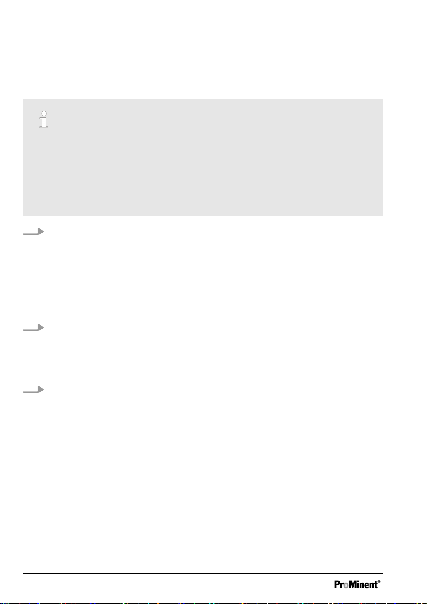
Fig. 1: Cuvette positioning (Ø 24 mm):
I. Seal
II. Marking with the white triangle
4. For the zero correction and test, the cuvette must be positioned in the
sample chamber in such a way that the marking with the white triangle (II.)
points towards the housing marking.
5. You must carry out the zero correction and test with the cuvette lid closed.
You must provide the cuvette lid with a sealing ring (I.) to prevent the
entrance of light into the sample chamber.
6. Formation of bubbles on the inside walls of the cuvette will result in faulty
measurements. Should this happen, seal the cuvette with the cuvette lid
and tip it back and forth to dissolve/remove the bubbles before carrying
out the test.
9
Page 10

A0938
General Information
7. It is important to prevent water getting into the sample chamber because
this leads to incorrect measurement results.
8. Dirt in the transparent sample chamber leads to incorrect measurement
results. The light entry surfaces should be checked at regular intervals and
cleaned as necessary.
Standard spectacle cleaning cloths and cotton buds are suitable for
cleaning.
9. Pronounced differences in temperature between the photometer and the
surroundings can lead to incorrect measurements, e.g. due to the forma‐
tion of condensation in the sample chamber and on the cuvette.
10. Protect the device from direct sunlight.
Fig. 2: Correct filling of the cuvette: Left = correct / right = incorrect
11. Fill the cuvette as shown in Fig. 2.
12. Insert the reagent tablets directly from the blister pack into the water
sample, without touching them with your fingers.
13. After use immediately close the dropping bottles containing the liquid
reagents by closing them with the screw caps of the same colour.
14. You must observe the sequence for the addition of reagents without fail.
10
Page 11
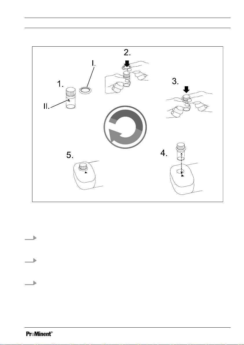
1.3 Adapter for 16 mm cuvettes
A0941
General Information
Fig. 3: Place the adapter for 16 mm cuvettes on the sample chamber
Insert the adapter for the 16 mm cuvette as shown in Fig. 3.
This adapter is required for all analysis methods which must be carried out using
a 16 mm cuvette.
11
Page 12
A0939
General Information
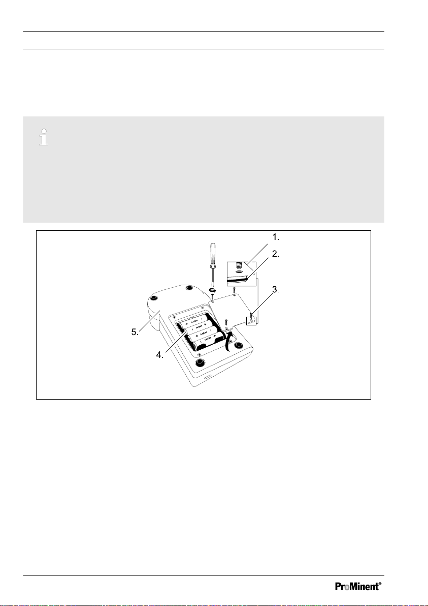
1.4 Operations carried out on the device
Battery replacement:
To ensure complete leak-tightness of the photometer, you must insert the
gasket (2) and screw on the battery compartment lid (1).
If the battery is removed for more than 1 minute from the device, then
when the device is switched on again with new inserted batteries, the
date/time program appears automatically.
Fig. 4: Battery replacement
1. Battery compartment cover
2. Seal
3. Screw
4. Batteries
5. Rear of the device
12
Page 13

2 Commissioning DT 1B
2.1 Commissioning
Switching on and zero correction
Scroll memory (SM)
With multi-parameter devices
the sequence of the various
methods is specified. After
switching on the device, the
method which was last selected
before the device was switched
off is automatically displayed.
This permits rapid access to a
favoured method.
1. Switch the device on using the
[ON/OFF]
ð
2. Select the
[MODE]
ð
Zero correction
3. Fill the cuvette up to the 10-ml
marking with the water sample,
see Fig. 2
4. Close the cuvette using the cuv‐
ette lid
5. Position the cuvette in the
sample chamber
ð
6. Press the key
key
The display outputs: The
last selected
key
The display outputs:
[METHOD]
Observe the correct posi‐
tioning of the cuvette.
[METHOD]
[METHOD]
.
using the
[ZERO/TEST]
.
Commissioning DT 1B
[METHOD]
ð
approximately 8 seconds.
[0.0.0]
play.
7. Remove the cuvette from the
sample chamber
Zero correction is ended.
ð
Analysis
8. Fill the cuvette up to the 10-ml
marking with the water sample,
see Fig. 2
9. Add reagents to the water
sample
The characteristic colouring
ð
develops.
10. Close the cuvette using the cuv‐
ette lid
11. Position the cuvette in the
sample chamber
12. Press the
so doing adhere to any possibly
required reaction time, see
flashes for
appears in the dis‐
[ZERO/TEST]
key, in
Ä „
Switching the countdown func‐
tion on“ on page 14
[METHOD]
ð
approximately 3 seconds.
The result is output to the
display.
flashes for
13
Page 14

Commissioning DT 1B
Switching the countdown function on
The result is automat‐
ically saved.
Repeating the analysis
Press the key
again
The process runs as
ð
described here
[ZERO/TEST]
on and zero correc‐
tion“ on page 13
New zero correction
Press the key
2 seconds
The process runs as
ð
described here
[ZERO/TEST]
on and zero correc‐
tion“ on page 13
Ä „Switching
.
for
Ä „Switching
.
NOTICE!
If reaction times are not
observed, the result may be
incorrect measurement results.
The countdown can only be
activated directly prior to a
measurement.
The countdown time equals 2
minutes and is non-adjustable.
The currently running count‐
down can be ended by
pressing the key [ZERO/TEST].
The measurement then takes
place immediately.
For methods with a reaction time, you
can optionally switch on a countdown
function:
1. Press the key
the key depressed
[!]
and then keep
2. Press the key
3. Release the
The countdown starts After
ð
the countdown has elapsed
(2 minutes), measurement
takes place automatically
[ZERO/TEST]
[!]
key
14
Page 15

Displaying stored data
The device has a ring buffer for 16 data records.
Fig. 5: Displaying stored data
1. Data record (n01 ... n16)
2. Year
3. Month/day
4. Time
5. Measured variable (e.g. chlorine,
dependent upon the device ver‐
sion)
6. Value in mg/l
Commissioning DT 1B
1. With the device switched on press the
[!]
key for more than 4 seconds then
release the key again
The display immediately switches to the memory menu.
ð
2. Press the
3. Press the
4. Press the
15
[MODE]
[ZERO/TEST]
[!]
key to scroll through the 16 data records
key to scroll through the values of a data record
key to return to the
[METHOD]
display
Page 16

Commissioning DT 1B
Display background lighting
Press the
ð
[!]
key
The display's background lighting switches on or off.
During measuring the background lighting switches off automati‐
cally.
16
Page 17

3 Operating Menu
3.1 Operating Menu Options
Operating menu selection
1. The device is switched off.
Press and hold down the
[MODE]
2. Use the
on the device
ð
3. Release the
4. The [!] key allows you to select
the following operating menu
items:
n
n Set date and time
n User adjustment
ð
5. Use the
date and time“
item (arrow at top right and
bottom left in the display)
key
[ON/OFF]
3 decimal points appear in
the display.
[diS]
= read out of stored
data
The selected operating
menu item is indicated by an
arrow in the display.
[!]
key to select the
key to switch
[MODE]
key
operating menu
„Set
Operating Menu
Setting date and time (24-hour
format)
Increase the value to be set by
pressing the [MODE] key.
Lower the value to be set by
pressing the [ZERO/TEST] key.
Pressing the [!] key takes you
to the next value to be set.
1. Press the
ð
2. Enter the year
3. Enter the month
4. Enter the day
5. Enter the hour
6. Enter the minutes
Enter the minutes in 10 minute
increments
Press the
Enter minutes in 1 minute incre‐
ments
7. After setting the minutes, press
the
ð
[MODE]
The parameter to be set
appears for 2 seconds.
key
[YYYY]
[MM]
[dd]
[hh]
[mm]
.
[!]
key
[!]
key
[IS SET]
play and the device auto‐
matically returns to meas‐
uring mode.
appears in the dis‐
17
Page 18

A1856
Operating Menu
3.2 Operating instructions
Display Meaning
Hi Measuring range exceeded or turbidity too
high.
Lo Measuring range undershot.
Change the batteries immediately, continuing
work impossible.
btLo Battery voltage for background lighting too low,
although measurement is possible.
With a method adjusted by the user, when the
result is shown in the display, an arrow appears
in the
[Cal]
position.
3.3 Error messages
Display Meaning
E 27/ E 28/
Light absorption too great. Cause e.g. dirty optics.
E 29
E 10 / E 11 Calibration factor outside the permissible range.
E 20 / E 21 Detector receives too much light.
E 23 / E24 /
Detector receives too much light.
E 25
E 22 The battery power was too low during the measurement.
Replace the battery.
E 70 Cl: Factory calibration not OK / deleted
E 71 Cl: User calibration not OK / deleted
E 72 Cl HR factory calibration not in order / deleted
E 73 Cl HR user calibration not OK / deleted
18
Page 19

Display Meaning
E 80 pH: Factory calibration not OK / deleted
E 81 pH: User calibration not OK / deleted
E 82 CyA: Factory calibration not OK / deleted
E 83 CyA: User calibration not OK / deleted
Operating Menu
19
Page 20

Analysis methods
4 Analysis methods
4.1 Procedure instructions when using liquid reagents
When calculating non-directly
determinable parameters from
individual measured values
error propagation based on the
possible tolerances of the indi‐
vidual methods must be consid‐
ered.
1. Cleaning the cuvettes Many
domestic cleaning agents con‐
tain reducing substances. Use
of these substances leads to
false low readings when meas‐
uring chlorine/bromine/chlorine
dioxide/ozone. To exclude this
measurement error, the cuv‐
ettes must not contain any sub‐
stances that have a chlorine
demand. Therefore the cuvettes
must be stored in a sodium
hypochlorite solution (0.1 g/l) for
one hour and then thoroughly
rinsed with deionised water.
2. For the relevant specification of
free chlorine and total chlorine
use a separate set of cuvettes
for each determination (see EN
ISO 7393-2, section. 5.3).
Label the cuvettes set on
the top and bottom so
that inadvertent inter‐
changing of the cuvettes
is not possible.
3. When preparing water samples
you must avoid the outgassing
of chlorine/bromine/chlorine
dioxide/ozone, e.g. by pipetting
and shaking. This applies partic‐
ularly for the dissolved gases
chlorine dioxide and ozone,
especially at temperatures >
30 °C. You must carry out the
analysis immediately after
taking the water sample.
4. The DPD colour development
takes place at a pH-value of 6.2
to 6.5. Therefore the reagents
contain a buffer for pH value
adjustment. You must ensure
strongly alkaline or acidic water
samples come within a pH
range between 6 and 7 (using
0.5 mol/l sulphuric acid solution
or 1 mol/l sodium hydroxide sol‐
ution).
5. Concentrations above the
measuring range with ...
n 4 mg/l chlorine when using
liquid reagents
n 9 mg/l bromine when using
liquid reagents
20
Page 21

Analysis methods
n 7.6 mg/l chlorine dioxide
when using liquid reagents
n 2.7 mg/l ozone when using
liquid reagents
may lead to results within
ð
the measuring range down
to 0 mg/l. In this case, you
must dilute the water
sample with water free from
oxidizing agent and repeat
the measurement (plausi‐
bility test).
6. Any turbidity that occurs during
the colour reaction leads to toohigh results. You can prevent
this error by pre-diluting the
sample with oxidizing agent-free
water. You must consider the
diluting ratio (e.g. 1:2) when cal‐
culating the measurement
result.
7. After use immediately close the
dropping bottles containing the
liquid reagents using the
respective screw caps of the
matching colour. Store the
reagent set at + 6 °C to + 10 °C.
8. The DPD method used
responds to many oxidising
media, hence you must ensure
that the selected oxidising agent
is present on its own. Mixtures,
e.g. from chlorine and chlorine
dioxide only yield total values.
These total values must then be
differentiated using additional
steps. To differentiate between
chlorine and chlorine dioxide,
see
[Chlorine with liquid reagent
method, section d.]
. To differen‐
tiate between chlorine and
ozone, see
[Chlorine with liquid reagent
method, section e.]
.
9. In water containing bromide and
iodide (primarily seawater), the
free and, as the case may be,
bound halogens formed by
chlorination are stated as
chlorine.
A steady increase in the meas‐
ured value of a water sample
therefore indicates that along‐
side the selected oxidising
agent (e.g. chlorine) a further
oxidising agent (e.g. bromide or
iodide) is present. This addi‐
tional oxidising agent (e.g. bro‐
mide or iodide) may due to cer‐
tain circumstances (many times
higher concentration, equilibria,
higher temperature) bleed
through into the measurement.
By working quickly and reading
off the measurement immedi‐
ately, the resulting error can be
minimised.
These interference effects
ð
are also known to occur with
these systems {combined
chlorine ⇛ free chlorine} and
{chloride ⇛ chlorine dioxide}.
21
Page 22

Analysis methods
4.2 Quantitative determination using liquid reagents
Chlorine with liquid reagents 0.01 ...
4.0 mg/l
Use the
[MODE]
key to select
[Cl]
.
a) Free chlorine
1. Take your cuvette set 1
2. In a 24 mm cuvette add a 10 ml
water sample and carry out a
zero correction, see
Ä „Switching on and zero cor‐
rection“ on page 13
3. Remove the cuvette from the
sample chamber and empty the
cuvette completely
Hold the dropping bottle upright
4.
and by slow pressing, add equal
sized drops into the cuvette:
n 6 drops ➨ DPD 1 buffer sol‐
ution
n 2 drops ➨ DPD 1 reagent
solution
Fill the cuvette up to the 10 ml
marking with the water sample
5. Close the cuvette using the cuv‐
ette lid
6. Mix the contents of the cuvette
by tipping it back and forth
7. Position the cuvette in the
sample chamber
Observe the correct posi‐
ð
tioning of the cuvette.
8. Press the key
[ZERO/TEST]
[METHOD]
ð
flashes for
approximately 3 seconds.
The result in mg/l of free
chlorine appears in the dis‐
play.
b) Total chlorine
1. Take your cuvette set 2
2. In a 24 mm cuvette add a 10 ml
water sample and carry out a
zero correction, see
Ä „Switching on and zero cor‐
rection“ on page 13
3. Remove the cuvette from the
sample chamber and empty the
cuvette completely
Hold the dropping bottle upright
4.
and by slow pressing, add equal
sized drops into the cuvette:
n 6 drops ➨ DPD 1 buffer sol‐
ution
n 2 drops ➨ DPD 1 reagent
solution
n 3 drops ➨ DPD 3 solution
Fill the cuvette up to the 10 ml
marking with the water sample
5. Close the cuvette with the cuv‐
ette lid and mix the contents by
tipping back and forth
6. Place the cuvette in the sample
chamber
Observe the correct posi‐
ð
tioning of the cuvette.
22
Page 23

Analysis methods
7. Switch the countdown on, see
Ä „ Switching the countdown
function on“ on page 14
this, press the
[ZERO/TEST]
Wait for the 2 minutes reac‐
ð
tion time to elapse
8. The METHOD symbol flashes
for approximately 3 seconds
The result in mg/l of total
ð
chlorine appears in the dis‐
play.
c) combined chlorine
[!]
key
and
. To do
Combined chlorine = total
chlorine minus free chlorine
Calculate the combined chlorine
d) Chlorine together with chlorine
dioxide
1. Fill a cuvette with a 10 ml water
sample
2. Insert a
directly from the foil into the
water sample and crush the
[GLYCINE]
rod
3. Close the cuvette with the cuv‐
ette lid and mix the contents by
tipping back and forth until the
tablet has dissolved
[GLYCINE]
tablet with a stirring
tablet
4. In a second 24 mm cuvette add
a 10 ml water sample and carry
out a zero correction, see
Ä „Switching on and zero cor‐
rection“ on page 13
5. Remove the cuvette from the
sample chamber for the zero
correction and empty the cuv‐
ette out
Hold the dropping bottle upright
6.
and by slow pressing, add equal
sized drops into the cuvette:
n 6 drops ➨ DPD 1 buffer sol‐
ution
n 2 drops ➨ DPD 1 reagent
solution
7. Pour the contents of the first
cuvette (
into the prepared cuvette
8. Close the cuvette with the cuv‐
ette lid and mix the contents by
tipping back and forth
9. Place the cuvette in the sample
chamber
ð
10. Press the key
ð
11. Remove the cuvette from the
sample chamber
12. Thoroughly clean the cuvette
and the cuvette lid
[GLYCINE]
Observe the correct posi‐
tioning of the cuvette.
solution)
[ZERO/TEST]
[METHOD]
approximately 3 seconds.
The display value
chlorine dioxide reappears
in the display.
flashes for
[G]
=
23
Page 24

Analysis methods
13. Hold the dropping bottle upright
and by slow pressing, add equal
sized drops into the cuvette:
n 6 drops ➨ DPD 1 buffer sol‐
ution
n 2 drops ➨ DPD 1 reagent
solution
Fill the cuvette up to the 10 ml
marking with the water sample
14. Close the cuvette using the cuv‐
ette lid
15. Mix the contents of the cuvette
by tipping it back and forth
16. Position the cuvette in the
sample chamber
Observe the correct posi‐
ð
tioning of the cuvette
17. Press the key
[METHOD]
ð
approximately 3 seconds.
The display value
of free chlorine plus chlorine
dioxide appears in the dis‐
play.
18. Remove the cuvette from the
sample chamber
19. Hold the dropping bottle upright
and by slow pressing, add equal
sized drops into the cuvette:
[ZERO/TEST]
flashes for
[A]
= sum
22. Position the cuvette in the
sample chamber
Observe the correct posi‐
ð
tioning of the cuvette
23. Switch the countdown on, see
Ä „ Switching the countdown
function on“ on page 14
this, press the
[ZERO/TEST]
Wait for the 2 minutes reac‐
ð
tion time to elapse
24.
[METHOD]
mately 3 seconds.
The display value
ð
of free chlorine plus com‐
bined chlorine plus chlorine
dioxide appears in the dis‐
play.
Calculation:
25.
n Chlorine dioxide (mg/l) =
display value
n Free chlorine (mg/l) = dis‐
play value
value
n Combined chlorine (mg/l) =
display value
play value
[!]
and
key
flashes for approxi‐
[A]
[G]
[A]
. To do
[C]
= sum
[G]
x 1.9
minus display
[C]
minus dis‐
n 3 drops ➨ DPD 3 solution
20. Close the cuvette using the cuv‐
ette lid
21. Mix the contents of the cuvette
by tipping it back and forth
24
Page 25

Analysis methods
d) Chlorine together with ozone
1. In a 24 mm cuvette add a 10 ml
water sample and carry out a
zero correction, see
Ä „Switching on and zero cor‐
rection“ on page 13
2. Remove the cuvette from the
sample chamber and empty the
cuvette completely
Hold the dropping bottle upright
3.
and by slow pressing, add equal
sized drops into the cuvette:
n 6 drops ➨ DPD 1 buffer sol‐
ution
n 2 drops ➨ DPD 1 reagent
solution
n 3 drops ➨ DPD 3 solution
Fill the cuvette up to the 10 ml
marking with the water sample
4. Close the cuvette using the cuv‐
ette lid
5. Mix the contents of the cuvette
by tipping it back and forth
6. Position the cuvette in the
sample chamber
Observe the correct posi‐
ð
tioning of the cuvette.
7. Switch the countdown on, see
Ä „ Switching the countdown
function on“ on page 14
this, press the
[ZERO/TEST]
Wait for the 2 minutes reac‐
ð
[!]
key
and
. To do
tion time to elapse
8. The METHOD symbol flashes
for approximately 3 seconds
The result of Total chlorine
ð
+ ozone = display value
[A]
appears in mg/l in the dis‐
play.
9. Remove the first cuvette from
the sample chamber
10. Thoroughly clean the cuvette
and the cuvette lid
11. Fill a second cuvette with a 10
ml water sample
12. Insert a
[GLYCINE]
tablet
directly from the foil into the
water sample and crush the
[GLYCINE]
tablet with a stirring
rod
13. Close the cuvette with the cuv‐
ette lid and mix the contents by
tipping back and forth until the
tablet has dissolved
14. Hold the dropping bottle upright
and by slow pressing, add equal
sized drops into the first cuvette:
n 6 drops ➨ DPD 1 buffer sol‐
ution
n 2 drops ➨ DPD 1 reagent
solution
n 3 drops ➨ DPD 3 solution
15. Pour the contents of the second
cuvette (
[GLYCINE]
solution)
into the prepared cuvette
16. Close the cuvette with the cuv‐
ette lid and mix the contents by
tipping back and forth
25
Page 26

Analysis methods
17. Place the cuvette in the sample
chamber
Observe the correct posi‐
ð
tioning of the cuvette.
18. Switch the countdown on, see
Ä „ Switching the countdown
function on“ on page 14
this, press the
[ZERO/TEST]
Wait for the 2 minutes reac‐
ð
tion time to elapse
19. The METHOD symbol flashes
for approximately 3 seconds
The result in mg/l of Total
ð
chlorine = display value
appears in the display.
Calculation:
20.
n Ozone (mg/l) = (Display
value
value
[!]
and
key
[A]
minus display
[G]
) x 0.67
. To do
[G]
Measuring tolerances when
determining the chlorine con‐
tent:
–
0 ... 1 mg/l: ± 0.05 mg/l
–
> 1 ... 2 mg/l: ± 0.10 mg/l
–
> 2 ... 3 mg/l: ± 0.20 mg/l
–
> 3 ... 4 mg/l: ± 0.30 mg/l
Bromine with liquid reagents 0.02 ... 9
mg/l
Use the
1. In a 24 mm cuvette add a 10 ml
[MODE]
water sample and carry out a
zero correction, see
key to select
[Br]
.
Ä „Switching on and zero cor‐
rection“ on page 13
2. Remove the cuvette from the
sample chamber and empty the
cuvette completely
Hold the dropping bottle upright
3.
and by slow pressing, add equal
sized drops into the cuvette:
n 6 drops ➨ DPD 1 buffer sol‐
ution
n 2 drops ➨ DPD 1 reagent
solution
n 3 drops ➨ DPD 3 solution
Fill the cuvette up to the 10 ml
marking with the water sample
4. Use the cuvette lid to seal the
cuvette
5. Mix the contents of the cuvette
by tipping it back and forth
6. Position the cuvette in the
sample chamber
Observe the correct posi‐
ð
tioning of the cuvette.
7. Switch the countdown on, see
Ä „ Switching the countdown
function on“ on page 14
this, press
Wait for the 2 minutes reac‐
ð
tion time to elapse
[!]
and
. To do
[ZERO/TEST]
26
Page 27

8.
[METHOD]
mately 3 seconds.
The result in mg/l of bromine
ð
appears in the display.
9.
Measuring tolerances
when determining the
bromine content:
–
–
–
–
flashes for approxi‐
0 ... 2.3 mg/l: ± 0.12
mg/l
> 2.3 ... 4.5 mg/l:
± 0.25 mg/l
> 4.5 ... 6.8 mg/l:
± 0.45 mg/l
> 6.8 ... 9 mg/l: ± 0.68
mg/l
Analysis methods
Chlorine dioxide with liquid reagents
0.02 ... 7.6 mg/l
Use the
1. In a 24 mm cuvette add a 10 ml
[MODE]
water sample and carry out a
zero correction, see
key to select
[CdO]
Ä „Switching on and zero cor‐
rection“ on page 13
2. Remove the cuvette from the
sample chamber and empty the
cuvette completely
Hold the dropping bottle upright
3.
and by slow pressing, add equal
sized drops into the cuvette:
n 6 drops ➨ DPD 1 buffer sol‐
ution
n 2 drops ➨ DPD 1 reagent
solution
.
Explanatory notes, see
ð
Ä Further information
on page 20
27
.
Fill the cuvette up to the 10 ml
marking with the water sample
4. Close the cuvette using the cuv‐
ette lid
5. Mix the contents of the cuvette
by tipping it back and forth
6. Position the cuvette in the
sample chamber
Observe the correct posi‐
ð
tioning of the cuvette.
7. Press the key
[METHOD]
ð
approximately 3 seconds.
The result in mg/l of chlorine
dioxide appears in the dis‐
play.
[ZERO/TEST]
flashes for
Page 28

Analysis methods
8.
Measuring tolerances
when determining the
chlorine dioxide content:
–
0 ... 1.9 mg/l: ± 0.1
mg/l
–
> 1.9 ... 3.8 mg/l:
± 0.2 mg/l
–
> 3.8 ... 5.7 mg/l:
± 0.4 mg/l
–
> 5.7 ... 7.6 mg/l:
± 0.6 mg/l
Ozone with liquid reagents 0.01 ... 2.7
mg/l
Use the
1. In a 24 mm cuvette add a 10 ml
[MODE]
water sample and carry out a
zero correction, see
key to select
[O3]
.
Ä „Switching on and zero cor‐
rection“ on page 13
2. Remove the cuvette from the
sample chamber and empty the
cuvette completely
Hold the dropping bottle upright
3.
and by slow pressing, add equal
sized drops into the cuvette:
n 6 drops ➨ DPD 1 buffer sol‐
ution
n 2 drops ➨ DPD 1 reagent
solution
n 3 drops ➨ DPD 3 solution
Fill the cuvette up to the 10 ml
marking with the water sample
4. Close the cuvette using the cuv‐
ette lid
5. Mix the contents of the cuvette
by tipping it back and forth
6. Position the cuvette in the
sample chamber
Observe the correct posi‐
ð
tioning of the cuvette.
7. Press the key
[METHOD]
ð
approximately 3 seconds.
The result in mg/l of ozone
appears in the display.
[ZERO/TEST]
flashes for
28
Page 29

Analysis methods
8.
Measuring tolerances
when determining the
ozone content:
–
0 ... 0.67 mg/l: ± 0.03
mg/l
–
> 0.67 ... 1.3 mg/l:
± 0.07 mg/l
–
> 1.3 ... 2.0 mg/l:
± 0.13 mg/l
–
> 2.0 ... 2.7 mg/l:
± 0.20 mg/l
Explanatory notes, see
ð
Ä Further information
on page 20
.
4.3 Procedure instructions when using tablets
When calculating non-directly
determinable parameters from
individual measured values
error propagation based on the
possible tolerances of the indi‐
vidual methods must be consid‐
ered.
1. Cleaning the cuvettes Many
domestic cleaning agents con‐
tain reducing substances. Use
of these substances leads to
false low readings when meas‐
uring chlorine/bromine/chlorine
dioxide/ozone. To exclude this
measurement error, the cuv‐
ettes must not contain any sub‐
stances that have a chlorine
demand. Therefore the cuvettes
must be stored in a sodium
hypochlorite solution (0.1 g/l) for
one hour and then thoroughly
rinsed with deionised water.
2. For the relevant specification of
free chlorine and total chlorine
use a separate set of cuvettes
for each determination (see EN
ISO 7393-2, section. 5.3).
29
Page 30

Analysis methods
Label the cuvettes set on
the top and bottom so
that inadvertent inter‐
changing of the cuvettes
is not possible.
3. When preparing water samples
you must avoid the outgassing
of chlorine/bromine/chlorine
dioxide/ozone, e.g. by pipetting
and shaking. This applies partic‐
ularly for the dissolved gases
chlorine dioxide and ozone,
especially at temperatures >
30 °C. You must carry out the
analysis immediately after
taking the sample.
4. The DPD colour development
takes place at a pH-value of 6.2
to 6.5. Therefore the reagents
contain a buffer for pH value
adjustment. You must ensure
strongly alkaline or acidic water
samples come within a pH
range between 6 and 7 (using
0.5 mol/l sulphuric acid solution
or 1 mol/l sodium hydroxide sol‐
ution).
5. Concentrations above
n 10 mg/l chlorine when using
tablets
n 22 mg/l bromine when using
tablets
n 19 mg/l chlorine dioxide
when using tablets
n 6 mg/l ozone when using
tablets
may lead to results within
ð
the measuring range down
to 0 mg/l. In this case, you
must dilute the water
sample with water free from
oxidizing agent and repeat
the measurement (plausi‐
bility test).
6. Turbidity (causes incorrect
measurements): For water sam‐
ples with High Calcium content*
and/or high conductivity when
using the
[DPD no. 1 tablet]
result can be the rendering
turbid of the water sample and
consequently incorrect meas‐
urements. In this case, you
must you must use the alterna‐
tive reagent tablet
[DPD no. 1 High Calcium]
turbidity only appears after the
addition of the
[DPD No. 3]
tablet, you can prevent this by
use of the
[DPD no. 1 High Calcium]
the
[DPD no. 3 High Calcium]
tablet. The
[DPD No. 1 High Calcium]
should only be used in conjunc‐
tion with the
[DPD No. 3 High Calcium]
*exact values cannot be
ð
specified, as the formation
of turbidity depends on the
type and composition of the
water sample.
7. The DPD method used
responds to many oxidising
media, hence you must ensure
that the selected oxidising agent
is present on its own. Mixtures,
the
. If the
and
tablet
.
30
Page 31

Analysis methods
e.g. of chlorine and chlorine
dioxide only yield total values.
These total values must then be
differentiated using additional
steps. To differentiate between
chlorine and chlorine dioxide,
see
[Chlorine with tablet method,
section D "Chlorine together
with chlorine dioxide"]
entiate between chlorine and
ozone, see
To differ‐
[Chlorine with tablet method]
8. In water containing bromide and
iodide, the free and, as the case
may be, bound halogens formed
by chlorination are stated as
chlorine. A steady increase in
the measured value of a water
sample therefore indicates that
alongside the selected oxidising
agent a further oxidising agent
is present. This oxidising agent
may due to certain circum‐
stances (many times higher
concentration, equilibria, higher
temperature) bleed through into
the measurement. By working
quickly and reading off the
measurement immediately, the
resulting error can be mini‐
mised.
These interference effects
ð
are also known to occur with
these systems {combined
chlorine ⇛ free chlorine} and
{chloride ⇛ chlorine dioxide}.
4.4 Quantitative determination using tablets
Fully dissolve tablets
Make sure that the tablets have
fully dissolved before starting
measurements. Otherwise
incorrect measurements may
result.
31
Page 32

Analysis methods
Chlorine with tablets 0.01 ... 6.0 mg/l
Use the
a) Free chlorine
1. Take your cuvette set 1
2. In a 24 mm cuvette add a 10 ml
[MODE]
water sample and carry out a
zero correction, see
key to select
[Cl]
.
Ä „Switching on and zero cor‐
rection“ on page 13
3. Remove the cuvette from the
sample chamber and empty the
cuvette down to the last few
drops
4. Insert a
directly from the foil into the
water sample and crush the
[DPD No. 1]
rod
5. Fill the cuvette up to the 10 ml
marking with the water sample
6. Close the cuvette with the cuv‐
ette lid and mix the contents by
tipping back and forth until the
tablet has dissolved
7. Position the cuvette in the
sample chamber
ð
8. Press the key
ð
[DPD No. 1]
tablet with a stirring
Observe the correct posi‐
tioning of the cuvette.
tablet
[ZERO/TEST]
[METHOD]
approximately 3 seconds.
flashes for
The result in mg/l of free
chlorine appears in the dis‐
play.
b) Total chlorine
1. Take your cuvette set 2
2. In a 24 mm cuvette add a 10 ml
water sample and carry out a
zero correction, see
Ä „Switching on and zero cor‐
rection“ on page 13
3. Remove the cuvette from the
sample chamber and empty the
cuvette down to the last few
drops
4. Insert a
directly from the foil into the
water sample and crush the
[DPD No. 1]
rod
5. Insert a
directly from the foil into the
water sample and crush the
[DPD No. 3]
rod
6. Fill the cuvette up to the 10 ml
marking with the water sample
7. Close the cuvette with the cuv‐
ette lid and mix the contents by
tipping back and forth until the
tablets have dissolved
8. Place the cuvette in the sample
chamber
ð
[DPD No. 1]
tablet with a stirring
[DPD No. 3]
tablet with a stirring
Observe the correct posi‐
tioning of the cuvette.
tablet
tablet
32
Page 33

Analysis methods
9. Switch the countdown on, see
Ä „ Switching the countdown
function on“ on page 14
this, press the
[ZERO/TEST]
Wait for the 2 minutes reac‐
ð
tion time to elapse
10. The METHOD symbol flashes
for approximately 3 seconds
The result in mg/l of total
ð
chlorine appears in the dis‐
play.
c) combined chlorine
[!]
key
and
. To do
Combined chlorine = total
chlorine minus free chlorine
Calculate the combined chlorine
d) Chlorine together with chlorine
dioxide
1. Fill a cuvette with a 10 ml water
sample
2. Insert a
directly from the foil into the
water sample and crush the
[GLYCINE]
rod
3. Close the cuvette with the cuv‐
ette lid and mix the contents by
tipping back and forth until the
tablet has dissolved
[GLYCINE]
tablet with a stirring
tablet
4. In a second 24 mm cuvette add
a 10 ml water sample and carry
out a zero correction, see
Ä „Switching on and zero cor‐
rection“ on page 13
5. Remove the cuvette from the
sample chamber for the zero
correction and empty the cuv‐
ette out
6. Insert a
directly from the foil into the
water sample and crush the
[DPD No. 1]
rod
7. Pour the contents of the first
cuvette (
into the prepared cuvette
8. Close the cuvette with the cuv‐
ette lid and mix the contents by
tipping back and forth until the
tablet has dissolved
9. Place the cuvette in the sample
chamber
ð
10. Press the key
ð
11. Remove the cuvette from the
sample chamber
12. Thoroughly clean the cuvette
and the cuvette lid
[DPD No. 1]
tablet with a stirring
[GLYCINE]
Observe the correct posi‐
tioning of the cuvette.
tablet
solution)
[ZERO/TEST]
[METHOD]
approximately 3 seconds.
The display value
(chlorine dioxide) reappears
in the display.
flashes for
[G]
33
Page 34

Analysis methods
13. Fill a cuvette with a few drops of
a water sample
14. Insert a
directly from the foil into the
water sample and crush the
[DPD No. 1]
rod
15. Fill the cuvette up to the 10 ml
marking with the water sample
16. Close the cuvette using the cuv‐
ette lid
17. Mix the contents of the cuvette
by tipping it back and forth, until
the tablet has dissolved
18. Position the cuvette in the
sample chamber
ð
19. Press the key
ð
20. Remove the cuvette from the
sample chamber
21. Insert a
directly from the foil into the
same water sample and crush
the
stirring rod
22. Close the cuvette using the cuv‐
ette lid
[DPD No. 1]
tablet with a stirring
Observe the correct posi‐
tioning of the cuvette.
tablet
[ZERO/TEST]
[METHOD]
approximately 3 seconds.
The display value
of free chlorine plus chlorine
dioxide) appears in the dis‐
play.
[DPD No. 3]
flashes for
[DPD No. 3]
tablet with a
[A]
tablet
(sum
23. Mix the contents of the cuvette
by tipping it back and forth, until
the tablet has dissolved
24. Position the cuvette in the
sample chamber
Observe the correct posi‐
ð
tioning of the cuvette.
25. Switch the countdown on, see
Ä „ Switching the countdown
function on“ on page 14
this, press the
[ZERO/TEST]
Wait for the 2 minutes reac‐
ð
tion time to elapse
26. The METHOD symbol flashes
for approximately 3 seconds
The display value
ð
of free chlorine plus com‐
bined chlorine plus chlorine
dioxide) appears in the dis‐
play.
Calculation:
27.
n Chlorine dioxide (mg/l) =
display value
n Free chlorine (mg/l) = dis‐
play value
value
n Combined chlorine (mg/l) =
display value
play value
[G]
[!]
key
[A]
[A]
and
. To do
[C]
(sum
[G]
x 1.9
minus display
[C]
minus dis‐
34
Page 35

Analysis methods
d) Chlorine together with ozone
1. In a 24 mm cuvette add a 10 ml
water sample and carry out a
zero correction, see
Ä „Switching on and zero cor‐
rection“ on page 13
2. Remove the cuvette from the
sample chamber and empty the
cuvette down to the last few
drops
3. Insert a
a
from the foil into the water
sample and crush the tablets
using a stirring rod
4. Fill the cuvette up to the 10 ml
marking with the water sample
5. Close the cuvette using the cuv‐
ette lid
6. Mix the contents of the cuvette
by tipping it back and forth, until
the tablets have dissolved
7. Position the cuvette in the
sample chamber
ð
8. Switch the countdown on, see
[DPD No. 1]
[DPD No. 3]
Observe the correct posi‐
tioning of the cuvette.
tablet and
tablet directly
Ä „ Switching the countdown
function on“ on page 14
this, press the
[ZERO/TEST]
Wait for the 2 minutes reac‐
ð
tion time to elapse
9. The METHOD symbol flashes
for approximately 3 seconds
[!]
key
and
. To do
The result of Total chlorine
ð
+ ozone = display value
appears in mg/l in the dis‐
play.
10. Remove the first cuvette from
the sample chamber
11. Thoroughly clean the cuvette
and the cuvette lid
12. Fill a second cuvette with a 10
ml water sample
13. Insert a
directly from the foil into the
water sample and crush the
[GLYCINE]
rod
14. Close the cuvette with the cuv‐
ette lid and mix the contents by
tipping back and forth until the
tablet has dissolved
15. Insert a
a
from the foil into the water
sample and crush the tablets
using a stirring rod
16. Pour the contents of the second
cuvette (
into the prepared cuvette
17. Close the cuvette with the cuv‐
ette lid and mix the contents by
tipping back and forth
18. Place the cuvette in the sample
chamber
ð
[GLYCINE]
tablet with a stirring
[DPD No. 1]
[DPD No. 3]
[GLYCINE]
Observe the correct posi‐
tioning of the cuvette.
tablet
tablet and
tablet directly
solution)
[A]
35
Page 36

Analysis methods
19. Switch the countdown on, see
Ä „ Switching the countdown
function on“ on page 14
this, press the
[ZERO/TEST]
Wait for the 2 minutes reac‐
ð
tion time to elapse
20. The METHOD symbol flashes
for approximately 3 seconds
The result in mg/l of Total
ð
chlorine = display value
appears in the display.
Calculation:
21.
n Ozone (mg/l) = (Display
value
value
[!]
and
key
[A]
minus display
[G]
) x 0.67
. To do
[G]
Measuring tolerances when
determining the chlorine con‐
tent:
–
0 ... 1 mg/l: ± 0.05 mg/l
–
> 1 ... 2 mg/l: ± 0.10 mg/l
–
> 2 ... 3 mg/l: ± 0.20 mg/l
–
> 3 ... 4 mg/l: ± 0.30 mg/l
–
> 4 ... 6 mg/l: ± 0.40 mg/l
Chlorine HR with tablet 5 ... 200 mg/l
For the analysis method
with tablet 5 ... 200 mg/l“
contained in the scope of supply is
required, see
Ä Chapter 1.3 „Adapter
for 16 mm cuvettes“ on page 11
1. Insert the adapter for the 16 mm
round cuvette in the device, see
„Chlor HR
the adapter
.
Ä Chapter 1.3 „Adapter for 16
mm cuvettes“ on page 11
2. In a 16 mm cuvette add an 8 ml
water sample and carry out a
zero correction, see
Ä „Switching on and zero cor‐
rection“ on page 13
3. Insert a
tablet and an
tablet directly from the foil into
the water sample and crush the
tablets using a stirring rod
4. Close the cuvette with the cuv‐
ette lid and mix the contents by
tipping back and forth until the
tablet has dissolved
5. Position the cuvette in the
sample chamber
ð
6. Press the key
ð
[CHLORINE HR (KI)]
[ACIDIFYING-GP]
Observe the correct posi‐
tioning of the cuvette.
[ZERO/TEST]
[METHOD]
approximately 3 seconds.
The result in mg/l of chlorine
appears in the display.
flashes for
36
Page 37

Measuring tolerances
when determining
chlorine HR:
–
± 5 mg/l
Oxidising agents
lead to multiple
results
All the oxidising
agents contained in
the water sample
react like chlorine
which leads to mul‐
tiple findings.
Ensure, by using suit‐
able methods and
measures that for
your particular
process, such mul‐
tiple finding cannot
occur or that such
multiple findings can
be allowed for in
another manner.
Analysis methods
Bromine with tablet 0.02 ... 13 mg/l
Use the
1. In a 24 mm cuvette add a 10 ml
[MODE]
water sample and carry out a
zero correction, see
key to select
[Br]
.
Ä „Switching on and zero cor‐
rection“ on page 13
2. Remove the cuvette from the
sample chamber and empty the
cuvette down to the last few
drops
3. Enter a
[DPD No. 3]
the foil into the water sample
and crush the tablet with a stir‐
ring rod
4. Fill the cuvette up to the 10 ml
marking with the water sample
5. Use the cuvette lid to seal the
cuvette
6. Mix the contents of the cuvette
by tipping it back and forth, until
the tablet has dissolved
7. Position the cuvette in the
sample chamber
ð
8. Switch the countdown on, see
[DPD No. 1]
tablet directly from
Observe the correct posi‐
tioning of the cuvette.
tablet and a
Ä „ Switching the countdown
function on“ on page 14
this, press
9. Press
[METHOD]
ð
approximately 3 seconds.
[!]
[ZERO/TEST]
and
flashes for
. To do
[ZERO/TEST]
.
37
Page 38

Analysis methods
10.
The result in mg/l of bromine
appears in the display.
Measuring tolerances
when determining the
bromine content:
–
0 ... 2.3 mg/l: ± 0.12
mg/l
–
> 2.3 ... 4.5 mg/l:
± 0.25 mg/l
–
> 4.5 ... 6.8 mg/l:
± 0.45 mg/l
–
> 6.8 ... 9 mg/l: ± 0.68
mg/l
–
> 9 ... 13 mg/l: ± 0.90
mg/l
Explanatory notes, see
ð
Ä Further information
on page 29
.
Chlorine dioxide with tablet 0.02 ... 11
mg/l
Use the
1. In a 24 mm cuvette add a 10 ml
[MODE]
water sample and carry out a
zero correction, see
key to select
[CdO]
Ä „Switching on and zero cor‐
rection“ on page 13
2. Remove the cuvette from the
sample chamber and empty the
cuvette down to the last few
drops of the water sample
3. Insert a
directly from the foil into the
water sample and crush the
tablet with a stirring rod
4. Fill the cuvette up to the 10 ml
marking with the water sample
5. Close the cuvette using the cuv‐
ette lid
6. Mix the contents of the cuvette
by tipping it back and forth, until
the tablet has dissolved
7. Position the cuvette in the
sample chamber
ð
8. Press the key
ð
[DPD No. 1]
Observe the correct posi‐
tioning of the cuvette.
tablet
[ZERO/TEST]
[METHOD]
approximately 3 seconds.
The result in mg/l of chlorine
dioxide appears in the dis‐
play.
flashes for
.
38
Page 39

Analysis methods
9.
Measuring tolerances
when determining the
chlorine dioxide content:
–
0 ... 1.9 mg/l: ± 0.1
mg/l
–
> 1.9 ... 3.8 mg/l:
± 0.2 mg/l
–
> 3.8 ... 5.7 mg/l:
± 0.4 mg/l
–
> 5.7 ... 7.6 mg/l:
± 0.6 mg/l
–
> 7.6 ... 11 mg/l: ± 0.8
mg/l
Ozone with tablet 0.01 ... 4 mg/l
Use the
1. In a 24 mm cuvette add a 10 ml
[MODE]
water sample and carry out a
zero correction, see
key to select
[O3]
.
Ä „Switching on and zero cor‐
rection“ on page 13
2. Remove the cuvette from the
sample chamber and empty the
cuvette down to the last few
drops
3. Insert a
a
from the foil into the water
sample and crush the tablets
using a stirring rod
4. Fill the cuvette up to the 10 ml
marking with the water sample
5. Close the cuvette using the cuv‐
ette lid
6. Mix the contents of the cuvette
by tipping it back and forth, until
the tablets have dissolved
7. Position the cuvette in the
sample chamber
ð
8. Press the key
ð
[DPD No. 1]
[DPD No. 3]
Observe the correct posi‐
tioning of the cuvette.
tablet and
tablet directly
[ZERO/TEST]
[METHOD]
approximately 3 seconds.
The result in mg/l of ozone
appears in the display.
flashes for
39
Page 40

Analysis methods
9.
Measuring tolerances
when determining the
ozone content:
–
0 ... 0.67 mg/l: ± 0.03
mg/l
–
> 0.67 ... 1.3 mg/l:
± 0.07 mg/l
–
> 1.3 ... 2.0 mg/l:
± 0.13 mg/l
–
> 2.0 ... 2.7 mg/l:
± 0.20 mg/l
–
> 2.7 ... 4.0 mg/l:
± 0.27 mg/l
Explanatory notes, see
ð
Ä Further information
on page 29
.
pH value with tablet 6.5 ... 8.4
Use the
1. In a 24 mm cuvette add a 10 ml
[MODE]
water sample and carry out a
zero correction, see
key to select
[PH]
.
Ä „Switching on and zero cor‐
rection“ on page 13
2. Insert a
[PHENOL RED PHOTO‐
METER]
foil into the water sample and
crush the tablet with a stirring
rod
3. Fill the cuvette up to the 10 ml
marking with the water sample
4. Close the cuvette using the cuv‐
ette lid
5. Mix the contents of the cuvette
by tipping it back and forth, until
the tablets have dissolved
6. Position the cuvette in the
sample chamber
ð
7. Press the key
ð
tablet directly from the
Observe the correct posi‐
tioning of the cuvette.
[ZERO/TEST]
[METHOD]
approximately 3 seconds.
The result is output to the
display as a pH value.
flashes for
40
Page 41

Analysis methods
8.
Measuring tolerances
when determining pH:
–
up to ± 0.3 pH units
ð
Remarks:
–
For the photo‐
metric pH value
determination
only use
[PHENOL RED]
tablets with black
foil printing, which
are labelled with
the term
[PHOTOMETER].
–
Water samples
with low carbo‐
nate hardness*
may result in
incorrect pH
values.
*KS4.3 < 0.7
mmol/l ≜ Total
alkalinity < 35
mg/l CaCO3.
–
pH values under
6.5 and greater
than 8.4 may lead
to results within
the measuring
range. A plausi‐
bility test (pH
meter) is recom‐
mended.
–
The accuracy of
pH values based
upon colorimetric
determination
depends on var‐
41
Page 42

Analysis methods
ious boundary
conditions (buffer
capacity of the
water sample, salt
content, etc.).
–
The salt content
of the water
sample effects the
result of the pho‐
tometric pH
measurement
(salt error), hence
this method is not
suitable for
checking the func‐
tioning of a poten‐
tiometric pH
measurement
(DIN 19643-2 ff,
paragraph 4.2.4.
functional check).
Cyanuric acid with CyA test tablet 1 ...
80 mg/l
Use the
1. In a 24 mm cuvette add a 10 ml
[MODE]
water sample and carry out a
zero correction, see
key to select
[CyA]
.
Ä „Switching on and zero cor‐
rection“ on page 13
2. Insert a
directly from the foil into the
water sample and crush the
tablet with a stirring rod
3. Fill the cuvette up to the 10 ml
marking with the water sample
4. Close the cuvette using the cuv‐
ette lid
5. Mix the contents of the cuvette
by tipping it back and forth, until
the tablets have dissolved
6. Position the cuvette in the
sample chamber
ð
7. Press the key
ð
[CyA TEST]
Observe the correct posi‐
tioning of the cuvette.
tablet
[ZERO/TEST]
[METHOD]
approximately 3 seconds.
The result in mg/l of cya‐
nuric acid appears in the
display.
flashes for
42
Page 43

8.
Measuring tolerances
when determining the
cyanuric acid content:
–
0 ... 25 mg/l: ± 5 mg/l
–
25 ... 50 mg/l: ± 8
mg/l
–
50 ... 80 mg/l: ± 10
mg/l
ð
Remarks:
–
Cyanuric acid
causes a very
finely distributed
turbidity with a
milky appearance
in the water
sample. Individual
particles should
not be traced
back to the pres‐
ence of cyanuric
acid, rather are
due to impurities
in the water
sample.
–
Dissolve the
tablet completely
(tilt from side to
side for approx. 1
minute). Undis‐
solved particles
may result in mul‐
tiple findings.
Analysis methods
43
Page 44

Calibration
5 Calibration
1. The device is switched off.
Press and hold down the
[MODE]
2. Use the
on the device
ð
3. Release the
4. The [!] key allows you to select
the following operating menu
items:
n
n Set date and time
n User calibration
ð
5. Use the
[CAL]
(arrow top right in the display)
key
[ON/OFF]
3 decimal points appear in
the display.
[diS]
= read out of stored
data
The selected menu item is
indicated by an arrow in the
display.
[!]
key to select the
operating menu item
key to switch
[MODE]
key
Chlorine (Cl) adjustment range
User adjustment
NOTICE!
Separate adjustment of the bro‐
mine, chlorine dioxide or ozone
measuring ranges is impos‐
sible. The device relies on the
adjustment of the chlorine
measuring range (Cl).
User adjustment (display in Adjust‐
ment mode ) =
Factory calibration (display in Adjust‐
ment mode ) =
1. Confirm the selection with
[cCAL]
[CCAL]
[MODE]
The display toggles between
ð
[CAL / METHOD]
2. Select the method to be
adjusted using the
3. Fill the cuvette up to the 10-ml
marking with the standard solu‐
tion, without adding reagents
.
[MODE]
key
4. Use the cuvette lid to seal the
cuvette
5. Position the cuvette in the
sample chamber
Observe the correct posi‐
ð
tioning of the cuvette
6. Press
[ZERO/TEST]
[METHOD]
ð
approximately 8 seconds.
flashes for
44
Page 45

Calibration
Confirmation of the zero cor‐
rection
with
7. Remove the cuvette from the
sample chamber and empty the
cuvette completely
8. Thoroughly clean the cuvette
and the cuvette lid
9. Fill the cuvette up to the 10-ml
marking with a standard solution
of known concentration and
introduce the reagents as
described under
[0.0.0]
[CAL]
alternates
.
Ä „Chlorine
with liquid reagents 0.01 ... 4.0
mg/l“ on page 22
or
Ä „a) Free
chlorine“ on page 32
10. Use the cuvette lid to seal the
cuvette
11. Position the cuvette in the
sample chamber
Observe the correct posi‐
ð
tioning of the cuvette.
12. Press
13. If the result matches the value
[ZERO/TEST]
[METHOD]
ð
approximately 3 seconds.
Confirmation of the result
alternates with
of the standard used, (within the
tolerance to be considered) you
can exit Adjustment mode by
pressing
flashes for
[ON/OFF]
[CAL]
.
Changing the displayed value:
Pressing the [MODE] key 1 x
increases the displayed result
by 1 digit.
Pressing the [ZERO/TEST] key
1 x reduces the displayed result
by 1 digit.
1. Repeatedly press the keys until
the displayed result matches the
value of the standard used
2. Press
[ON/OFF]
The new correction factor is
ð
calculated and saved in the
user adjustment level.
Confirmation of the adjust‐
ment appears in the display
for 3 seconds.
45
Page 46

Calibration
Return to the factory calibration
Returning from user adjustment
to factory calibration is only
possible simultaneously for all
methods.
With a method adjusted by the
user, when the result is shown
in the display, an arrow
appears in the [Cal] position.
Proceed as follows to return the
device to the factory calibration, pro‐
ceed as follows:
1. Device is switched off. Simulta‐
neously press
[MODE]
and
[ZERO/TEST]
2. Switch the device on using the
[ON/OFF]
ð
3. The display toggles between:
[SEL]
ð
4. or
5. The display toggles between:
[SEL]
key
After approximately 1
second, release
and
[ZERO/TEST]
and
[CAL]
The device is in the as-sup‐
plied condition (
for Select).
and
[cAL]
[MODE]
.
[SEL]
stands
The device operates with an
ð
adjustment performed by
the user. If the user adjust‐
ment is to be retained,
switch off the device using
[ON/OFF]
the
6. Pressing
simultaneously activate factory
calibration for all methods
7. The display toggles between
[SEL]
8. Switch the device off using the
[ON/OFF]
[MODE]
and
key
key.
lets you
[CAL]
46
Page 47

Technical Data
6 Technical Data
Device two wavelengths, automatic wavelength selection,
colorimeter with direct measured value display
Optics LEDs, interference filter (IF) and photo sensor at the
transparent sample chamber
Wavelength specifications of the interference filter:
n 530 nm Δλ = 5 nm
n 560 nm Δλ = 5 nm
Wavelength precision ± 1 nm
Photometric precision* 3% FS (Full Scale) (T = 20°C ... 25°C)
Photometric resolution 0.01 A (Absorption units)
Power supply 4 batteries (Mignon AA/LR 6)
Operating time approx. 53 h operating time or 15,000 measure‐
ments in continuous operation with background
lighting switched off
Auto-OFF Automatic device switch-off 10 minutes after the last
key was pressed
Display Backlit LCD (at the press of a key)
Memory internal ring buffer for 16 data records
Time Real time clock and date
Calibration (manufac‐
turer) / Adjustment
(user)
Factory calibration and user adjustment.
Return to factory calibration is possible.
Dimensions 190 x 110 x 55 mm (L x W x H)
Weight Basic device approx. 455 g (with batteries)
*measured with standard solutions
47
Page 48

Technical Data
Ambient conditions Temperature: 5 ... 40 °C
Relative humidity: 30 ... 90% (non-condensing)
Water-tight similar to IP 68 (1 hour at 0.1 m); buoyant device
*measured with standard solutions
The specified device precision is only obtained when the original reagent
systems are used.
48
Page 49

Consumables and Spare Parts
7 Consumables and Spare Parts
Consumables
Material Part number
DPD-1 tablets (100 no.) 1061892
DPD-3 tablets (100 no.) 1061893
Phenol red tablets R 175 (100 no.) 305532
Cyanuric acid tablets R 263 (100 no.) 1039744
CHLORINE HR (KI) tablets (100 no.) 1075056
ACIDIFYING GP tablets (100 no.) 1075057
Glycine tablets (20 no.) 1061944
Spare parts
Material Part number
3 no. round cuvettes (d = 24 mm, h = 48 mm) with lid
1007566
(replacement cuvettes) for:
n DPD identification
n Phenol red identification
n Cyanuric acid identification
5 no. round cuvettes (d = 16 mm, h = 90 mm) with lid
1024072
(replacement cuvettes) for:
n Chlorine HR identification with a tablet
49
Page 50

Standards Complied with and Declaration of Conformity
8 Standards Complied with and Declaration of Conformity
Declaration of Conformity
You will find the EC Declaration of
Conformity to download on our home‐
page.
Standards complied with
EC EMC Directive (2004/108/EC)
EN 61326 - 1
50
Page 51

9 Index
Index
1, 2, 3 ...
16 mm cuvette adapter ......... 11
A
Action, step by step .............2
B
Battery compartment cover ...... 12
Battery replacement ........... 12
Bromine with liquid reagents
0.02 ... 9 mg/l ................ 26
Bromine with tablet 0.02 ... 13
mg/l ........................37
C
Chlorine dioxide with liquid
reagents 0.02 ... 7.6 mg/l ....... 27
Chlorine dioxide with tablet
0.02 ... 11 mg/l ............... 38
Chlorine HR with tablet 5 ... 200
mg/l ........................36
Chlorine together with chlorine
dioxide (liquid reagents) ........ 23
Chlorine together with chlorine
dioxide (tablet) ............... 33
Chlorine together with ozone
(liquid reagents) .............. 25
Chlorine together with ozone
(tablet) ..................... 35
Combine chlorine (tablet) ....... 33
Combined chlorine (liquid
reagents) ................... 23
Consumables ................ 49
Countdown .................. 14
Cyanuric acid with CyA test tablet
1 ... 80 mg/l ..................42
D
Danger from hazardous sub‐
stances! ..................... 5
Date and time (24-hour format) ...17
Declaration of Conformity ....... 50
Degree of protection IP 68 ...... 47
Display background lighting ..... 16
Displaying stored data ......... 15
E
EN ISO 7393-2, section 5.3 ...20, 29
Error messages .............. 18
F
Free chlorine (liquid reagents) ... 22
Free chlorine (tablet) ...........32
G
General non-discriminatory
approach .....................2
I
IP 68 ....................... 47
51
Page 52

Index
L
Links to elements or sections of
these instructions or other appli‐
cable documents ...............2
M
Material safety data sheet ........5
More symbols ................. 2
N
Non-discriminatory approach ..... 2
O
Ozone with liquid reagents 0.01 ...
2.7 mg/l .....................28
Ozone with tablet 0.01 ... 4 mg/l .. 39
P
pH value with tablet 6.5 ... 8.4 ....40
Photometer leak-tightness ...... 12
Q
Question: For which measured
variable can I perform an adjust‐
ment? ...................... 44
Question: How can I read stored
data? .......................15
Question: How can I return to the
factory calibration? ............ 46
Question: How do I adjust the
date and time? ............... 17
Question: How do I carry out a
zero correction? .............. 13
Question: How do I carry out the
zero correction? ............... 8
Question: How do I change the
battery? .....................12
Question: How do I enter the
values determined by the adjust‐
ment into the device? .......... 45
Question: How do I perform a
user adjustment? ............. 44
Question: How do I switch the
background lighting of the display
off and on? .................. 16
Question: How do I switch the
countdown on? ............... 14
Question: What does the standard
scope of supply include? .........6
Question: What must it clean and
how? ........................8
Question: What sort of consuma‐
bles are available? ............ 49
Question: What spare parts are
available? ................... 49
Question: What type of error mes‐
sages are there? ..............18
Question: Where can I find the
Declaration of Conformity? ...... 50
Question: Which standards are
complied with? ............... 50
R
Repeating the analysis ......... 14
Return to the factory calibration .. 46
52
Page 53

Index
S
Safety data sheets ............. 8
Spare parts .................. 49
Standard scope of supply ........ 6
Standards complied with ........50
Switching on and zero correction . 13
T
Technical Data ............... 47
Total chlorine (liquid reagents) ... 22
Total chlorine (tablet) .......... 32
Z
Zero correction ............. 8, 13
53
Page 54

54 55
Page 55

Page 56

ProMinent GmbH
Im Schuhmachergewann 5 - 11
69123 Heidelberg, Germany
Telephone: +49 6221 842-0
Fax: +49 6221 842-419
Email: info@prominent.com
Internet: www.prominent.com
985629, 3, en_GB
© 2017
 Loading...