

ProMinent DULCOTEST DO 3-mA-20 ppm Assembly And Operating Instructions Manual
Assembly and operating instructions
A2613
DULCOTEST® sensors for dissolved oxygen
Type: DO 3-mA-20 ppm
EN
Please carefully read these operating instructions before use. · Do not discard.
The operator shall be liable for any damage caused by installation or operating errors.
The latest version of the operating instructions are available on our homepage.
Target group: Instructed person982373 BA DT 061 12/18 EN

Supplemental directives
General non-discriminatory approach In order to make it easier to read, this docu‐
ment uses the male form in grammatical struc‐
tures but with an implied neutral sense. It is
aimed equally at both men and women. We
kindly ask female readers for their under‐
standing in this simplification of the text.
Supplementary information
Please read the supplementary information in its entirety.
Information
This provides important information relating to the correct operation of the unit or is intended
to make your work easier.
Warning information
Warning information includes detailed descriptions of the hazardous situation, see
‘Labelling of Warning Information’ on page 8
The following symbols are used to highlight instructions, links, lists, results and other elements in
this document:
.
Ä Chapter 2.1
Tab. 1: More symbols
Symbol Description
Action, step by step.
⇨ Outcome of an action.
Links to elements or sections of these instructions or other applicable docu‐
ments.
n
[Button]
List without set order.
Display element (e.g. indicators).
Operating element (e.g. button, switch).
2

Symbol Description
Supplemental directives
‘Display /GUI’
CODE
Screen elements (e.g. buttons, assignment of function keys).
Presentation of software elements and/or texts.
3

Table of contents
Table of contents
1 Function.................................................................................................................................. 5
1.1 Measuring principle........................................................................................................ 5
1.2 Construction and function............................................................................................... 6
1.3 Scope of delivery............................................................................................................ 7
2 Safety...................................................................................................................................... 8
2.1 Labelling of Warning Information.................................................................................... 8
2.2 User qualification.......................................................................................................... 10
2.3 General safety information........................................................................................... 11
2.4 Intended use................................................................................................................. 11
3 How to store and transport the sensor.................................................................................. 12
3.1 Storage......................................................................................................................... 12
3.2 Transport...................................................................................................................... 12
4 Assembly and installation...................................................................................................... 13
4.1 Installation on a PVC immersion tube.......................................................................... 14
4.2 Installation in the bypass fitting DGMa......................................................................... 15
4.3 Installation in bypass fitting DLG III.............................................................................. 16
4.4 Electrical connection.................................................................................................... 18
5 Preparation for the measurement......................................................................................... 20
6
Calibration with the DULCOMETER ® DACb........................................................................ 21
6.1 Calibration on air.......................................................................................................... 21
6.2 Calibration in water using a reference measurement................................................... 21
6.3 Calibrating the zero point............................................................................................. 21
7 Maintenance and troubleshooting......................................................................................... 22
7.1 Dismantling the sensor................................................................................................. 22
7.2 Replacing the sensor cap............................................................................................. 22
7.3 Cleaning....................................................................................................................... 23
7.4 Troubleshooting............................................................................................................ 23
8 Disposal of used parts........................................................................................................... 24
9 Parts and accessories........................................................................................................... 25
10 Technical data....................................................................................................................... 26
10.1 Standards and regulations complied with................................................................... 27
11 Index..................................................................................................................................... 28
4

1 Function
The DULCOTEST® sensor, type DO 3, is used
for measurement of the partial pressure of dis‐
solved oxygen and the measured variables
derived from this:
n Oxygen concentration in aqueous liquids
in mg/l or ppm,
n Degree of oxygen saturation in aqueous
liquids in %
The sensor type DO 3 is used for measurement
of the concentration of dissolved oxygen in
fresh water and salt water. The applications
specifically include
n The control and monitoring of aeration pro‐
cesses in clarification plants,
n Monitoring of fish farming facilities
n The aeration of raw water in water works
n Assessment of the quality of surface
water.
All wetted materials are suitable for fresh water
and salt water.
Function
1.1 Measuring principle
The sensor type DO 3 is based on the optical
measurement of a fluorescence beam. The flu‐
orescence beam is weakened depending on
the partial pressure of the oxygen in the water.
The measurement is done in pulsed mode, with
the relaxation time of the fluorescence beam
being determined.
5
A2646
4
3
2
1
5
Function
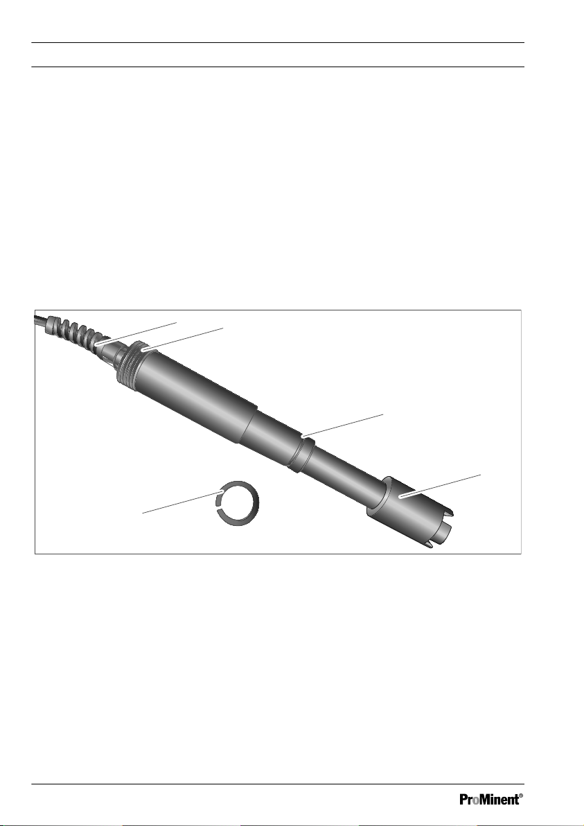
1.2 Construction and function
A sensor cap is screwed onto the optical window of the sensor type DO 3 integrated in the sensor
shaft. The sensor cap contains fluorescence dye immobilised on a carrier. A black protective cap is
attached to the sensor cap. The sensor has a 10-metre long fixed cable. The sensor can be
immersed under water. The sensor shaft has an Rp1” thread on the cable side. The adapter
included in the scope of delivery is screwed onto the thread to enable the sensor to be connected to
an immersion tube at an angle of 45°. The middle part of the sensor shaft has a groove for a clamp
disc. The clamp ring threaded connection is used to fix the sensor into a suitable ProMinent bypass
fitting. The sensor shaft contains a temperature sensor (Pt 1000). The temperature sensor is used
for internal temperature correction of the measuring signal. The temperature sensor is connected to
the measuring equipment. The sensor is factory calibrated. The temperature-corrected, calibrated
and galvanically isolated 4 ... 20 mA measuring signal leaves the sensor along 2 lines. The supply
voltage is also fed along the same lines (two-line technology).
Fig. 1: Construction of the sensor
1 Fixed cable, 10 metres
2 Rp1” thread
3 Sensor shaft with groove for the clamp disc
4 Sensor head area with protective cap
5 Clamp disc
6
A2643
3
2
1
5
4
6
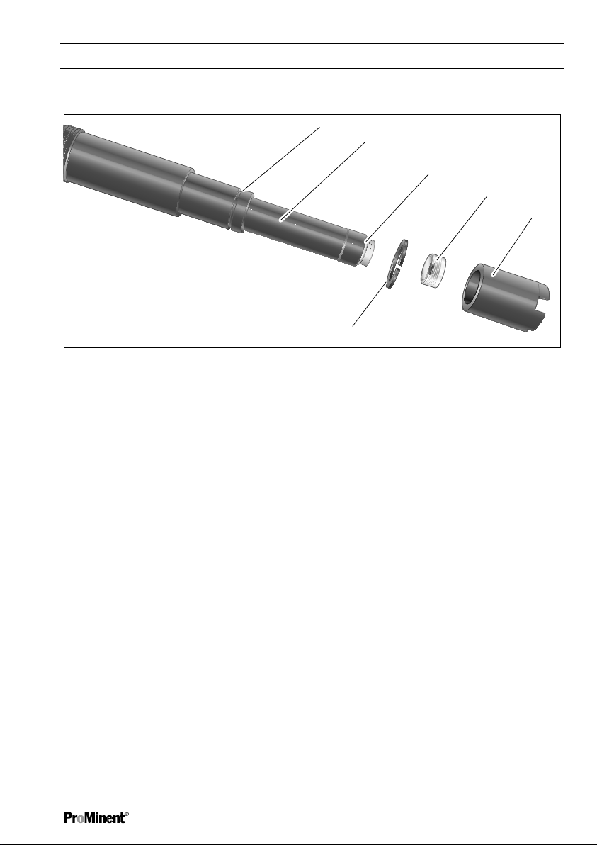
Fig. 2: Construction in the sensor head area
1 Groove for the clamp disc for connection to
the bypass fitting
2 Sensor shaft
3 O-ring
Function
4 Sensor cap with fluorescence dye
5 Protective cap (bite protection for the appli‐
cation: fish farming)
6 Clamp disc
1.3 Scope of delivery
Please first check the scope of delivery of
sensor type DO 3, order number 1094609
n 1 no. clamp disc,
n 1 no. clamp disc, replacement,
n 1 no. protective cap on the sensor head,
n 1 no. adapter: with Rp1” thread, PVC-U,
n 1 no. 45° angle, PVC, DN32,
n 1 no. assembly and operating instructions.
7

Safety
2 Safety
2.1 Labelling of Warning Infor‐
mation
Introduction
These operating instructions provide informa‐
tion on the technical data and functions of the
product. These operating instructions provide
detailed warning information and are provided
as clear step-by-step instructions.
The warning information and notes are categor‐
ised according to the following scheme. A
number of different symbols are used to denote
different situations. The symbols shown here
serve only as examples.
WARNING!
Nature and source of the danger
Possible consequence: Fatal or very
serious injuries.
Measure to be taken to avoid this
danger.
– Denotes a possibly hazardous sit‐
uation. If the situation is disre‐
garded, it could result in fatal or
very serious injuries.
DANGER!
Nature and source of the danger
Consequence: Fatal or very serious
injuries.
Measure to be taken to avoid this
danger.
Description of hazard
– Denotes an immediate threatening
danger. If the situation is disre‐
garded, it will result in fatal or very
serious injuries.
CAUTION!
Nature and source of the danger
Possible consequence: Slight or minor
injuries. Material damage.
Measure to be taken to avoid this
danger.
– Denotes a possibly hazardous sit‐
uation. If the situation is disre‐
garded, it could result in slight or
minor injuries. May also be used
as a warning about material
damage.
8

NOTICE!
Nature and source of the danger
Damage to the product or its surround‐
ings.
Measure to be taken to avoid this
danger.
– Denotes a possibly damaging sit‐
uation. If the situation is disre‐
garded, the product or an object in
its vicinity could be damaged.
Type of information
Hints on use and additional information.
Source of the information. Additional
measures.
–
Denotes hints on use and other
useful information. It does not indi‐
cate a hazardous or damaging sit‐
uation.
Safety
9

Safety
2.2 User qualification
WARNING!
Danger of injury with inadequately qualified personnel
The operator of the system / equipment is responsible for ensuring that the qualifications are
fulfilled.
If inadequately qualified personnel work on the unit or loiter in the hazard zone of the unit,
this could result in dangers that could cause serious injuries and material damage.
– All work on the unit should therefore only be conducted by qualified personnel.
– Unqualified personnel should be kept away from the hazard zone.
The pertinent accident prevention regulations, as well as all other generally acknowledged
safety regulations, must be adhered to.
Training Definition
Instructed personnel An instructed person is deemed to be a person who has been
instructed and, if required, trained in the tasks assigned to him and pos‐
sible dangers that could result from improper behaviour, as well as
having been instructed in the required protective equipment and protec‐
tive measures.
Trained user A trained user is a person who fulfils the requirements made of an
instructed person and who has also received additional training specific
to the system from the manufacturer or another authorised distribution
partner.
Trained, qualified per‐
sonnel
A trained, qualified employee is deemed to be a person who is able to
assess the tasks assigned to him and recognize possible hazards
based on his training, knowledge and experience, as well as knowledge
of pertinent regulations. A trained, qualified employee must be able to
perform the tasks assigned to him independently with the assistance of
drawing documentation and parts lists. The assessment of a person's
technical training can also be based on several years of work in the rel‐
evant field.
10
 Loading...