

Page 1

Assembly and operating instructions
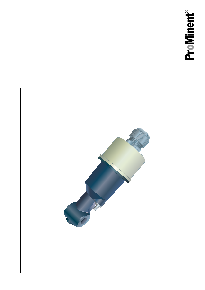
A2632
DULCOTEST® sensor ICT 5 and ICT 5-IMA
Sensor for electrical conductivity
EN/DE
Please carefully read these operating instructions before use. · Do not discard.
The operator shall be liable for any damage caused by installation or operating errors.
The latest version of the operating instructions are available on our homepage.
982358 BA DT 157 10/18 DE/EN
Page 2

Overall Table of Contents
Overall Table of Con‐
tents
EN
DULCOTEST® sensor ICT 5 and ICT
5-IMA Sensor for electrical conduc‐
tivity..................................................... 4
1 Introduction.................................... 8
1.1 Measuring principle.................... 8
1.2 Construction and function of
the sensor................................... 9
1.3 Nameplate................................ 12
1.4 Scope of delivery...................... 12
2 Safety and responsibility............. 13
2.1 Labelling of Warning Informa‐
tion............................................ 13
2.2 User qualification...................... 15
2.3 General safety information....... 16
2.4 Intended use............................. 17
2.5 Information in the event of an
emergency................................ 17
3 How to store and transport the
sensor.......................................... 18
3.1 Storage..................................... 18
3.2 Transport.................................. 18
4 Assembly and installation............ 19
4.1 Installation of sensor type ICT
5............................................... 20
4.2 Installation of sensor type ICT
5-IMA........................................ 23
4.3 Electrical installation................. 24
5 Maintenance................................ 26
6 Rectifying faults and malfunc‐
tions............................................. 27
7 Disposal of used parts................. 28
8 Accessories................................. 29
9 Technical data............................. 30
9.1 General data............................. 30
9.2 Certification/Test marks............ 31
9.3 Permitted process pressure..... 32
10 Dimensions................................ 33
DE
DULCOTEST® Sensor ICT 5 und
ICT 5-IMA Sensor für elektrolytische
Leitfähigkeit....................................... 36
1 Einleitung..................................... 40
1.1 Messprinzip.............................. 40
1.2 Aufbau und Funktion des Sen‐
sors........................................... 41
1.3 Typenschild.............................. 44
1.4 Lieferumfang............................ 44
2 Sicherheit und Verantwortung..... 45
2.1 Kennzeichnung der Warnhin‐
weise........................................ 45
2.2 Benutzer-Qualifikation.............. 47
2.3 Allgemeine Sicherheitshin‐
weise........................................ 48
2.4 Bestimmungsgemäße Verwen‐
dung......................................... 49
2.5 Angaben für den Notfall............ 49
3 So lagern und transportieren Sie
den Sensor.................................. 50
3.1 Lagerung.................................. 50
3.2 Transport.................................. 50
4 Montage und Installation............. 51
4.1 Montage des Sensortyps ICT
5............................................... 52
4.2 Montage des Sensortyps ICT
5-IMA........................................ 55
4.3 Elektrische Installation.............. 56
5 Wartung....................................... 58
6 Fehler und Störungen beheben... 59
7 Altteileentsorgung........................ 60
8 Zubehör....................................... 61
9 Technische Daten....................... 62
9.1 Allgemeine Daten..................... 62
9.2 Zulassungen/Prüfzeichen......... 63
9.3 Zulässiger Prozessdruck.......... 64
2
Page 3

10 Abmessungen........................... 65
Overall Table of Contents
3
Page 4
Assembly and operating instructions
A2632
DULCOTEST® sensor ICT 5 and ICT 5-IMA
Sensor for electrical conductivity
EN
Please carefully read these operating instructions before use. · Do not discard.
The operator shall be liable for any damage caused by installation or operating errors.
The latest version of the operating instructions are available on our homepage.
982358 BA DT 157 10/18 DE/EN
Page 5

Supplemental directives
General non-discriminatory approach In order to make it easier to read, this docu‐
ment uses the male form in grammatical struc‐
tures but with an implied neutral sense. It is
aimed equally at both men and women. We
kindly ask female readers for their under‐
standing in this simplification of the text.
Supplementary information
Please read the supplementary information in its entirety.
Information
This provides important information relating to the correct operation of the unit or is intended
to make your work easier.
Warning information
Warning information includes detailed descriptions of the hazardous situation, see
‘Labelling of Warning Information’ on page 13
The following symbols are used to highlight instructions, links, lists, results and other elements in
this document:
.
Ä Chapter 2.1
Tab. 1: More symbols
Symbol Description
Action, step by step.
⇨ Outcome of an action.
Links to elements or sections of these instructions or other applicable docu‐
ments.
n
[Button]
5
List without set order.
Display element (e.g. indicators).
Operating element (e.g. button, switch).
Page 6

Supplemental directives
Symbol Description
‘Display /GUI’
CODE
Screen elements (e.g. buttons, assignment of function keys).
Presentation of software elements and/or texts.
6
Page 7

Table of contents
Table of contents
1 Introduction............................................................................................................................. 8
1.1 Measuring principle........................................................................................................ 8
1.2 Construction and function of the sensor......................................................................... 9
1.3 Nameplate.................................................................................................................... 12
1.4 Scope of delivery.......................................................................................................... 12
2 Safety and responsibility....................................................................................................... 13
2.1 Labelling of Warning Information.................................................................................. 13
2.2 User qualification.......................................................................................................... 15
2.3 General safety information........................................................................................... 16
2.4 Intended use................................................................................................................. 17
2.5 Information in the event of an emergency.................................................................... 17
3 How to store and transport the sensor.................................................................................. 18
3.1 Storage......................................................................................................................... 18
3.2 Transport...................................................................................................................... 18
4 Assembly and installation...................................................................................................... 19
4.1 Installation of sensor type ICT 5................................................................................... 20
4.2 Installation of sensor type ICT 5-IMA........................................................................... 23
4.3 Electrical installation..................................................................................................... 24
5 Maintenance.......................................................................................................................... 26
6 Rectifying faults and malfunctions......................................................................................... 27
7 Disposal of used parts........................................................................................................... 28
8 Accessories........................................................................................................................... 29
9 Technical data....................................................................................................................... 30
9.1 General data................................................................................................................. 30
9.2 Certification/Test marks................................................................................................ 31
9.3 Permitted process pressure......................................................................................... 32
10 Dimensions........................................................................................................................... 33
7
Page 8

Introduction
1 Introduction
These operating instructions provide informa‐
tion on the technical data and functions of the
DULCOTEST® sensor for inductive conduc‐
tivity, ICT 5 and ICT-IMA.
Sensor type ICT 5 is designed for continuous
flow operation.
Sensor type ICT 5-IMA is integrated in an
immersion tube for immersion in a storage tank
and in an open channel.
The sensor records the electrolytic conductivity
of an aqueous process liquid online. Both types
of sensor work on the basis of an inductive
measuring principle. The sensor is almost
maintenance-free due to the inductive meas‐
uring process. Solid deposits and fatty or oily
films on the surface of the sensor have no
impact on its measuring precision. The sensor
is particularly suitable for measuring high con‐
ductivities of up to 2000 mS/cm. A stand-alone
temperature sensor (Pt1000) with a short
response time records the process tempera‐
ture. The temperature sensor is enclosed within
a protective stainless steel sleeve. Tempera‐
ture correction of the conductivity measurement
in the connected controller is provided for by
the temperature sensor (Pt1000).
You can also use both types of sensor in conta‐
minated water or in aggressive media, which is
chemically inert to PVC/EPDM and/or PP/
EPDM (depending on the design of the sensor).
1.1 Measuring principle
The electrolytic conductivity is measured with
an inductive sensor. The sensor contains a
transmission and receiver coil. Sine alternating
voltage feeds the transmission coil. A sample
flow is induced into the receiver coil depending
on the conductivity of the liquid to be meas‐
ured. The sample flow is proportional to the
conductivity of the medium.
Typical applications
The sensor is predominantly designed for appli‐
cations in water treatment and for water moni‐
toring, e.g.:
n Contaminated waste water and process
water
n Air conditioning plants and chillers
n Blowdown control in cooling towers,
n Flushing baths,
n Vehicle washing systems,
n Salt water desalination (feed),
n Swimming pool water control.
8
Page 9

A2617
4
3
2
1
5
Introduction
1.2 Construction and function of the sensor
The inductive transducer of the two types of sensor ICT 5 and ICT 5-IMA consists of a hermetically
sealed polypropylene (PP) body. A transmission coil and a receiver coil are incorporated in the
transducer. A flow opening in the sensor (sensor eye) permits the measuring medium to flow
through. There is galvanic isolation between the sample medium and the signal output. A standalone temperature sensor (Pt1000) with a short response time records the process temperature. The
temperature sensor is enclosed within a protective stainless steel sleeve.
Fig. 1: Components
1 PP sensor body
2 Transmission coil
3 Sensor eye through which the sample
medium flows
4 Receiver coil
5 Temperature sensor, stand-alone, enclosed
within a stainless steel sleeve
9
Page 10
A2641
Introduction
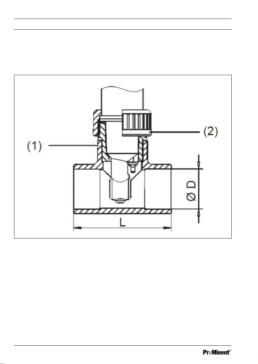
Sensor type ICT 5
The sensor type ICT5 is connected to a standard DN40 T-piece (on site) using a threaded socket
and a union nut for operation in the flow.
Fig. 2: Sensor type ICT 5
1. Threaded socket, G 1 1/2” (PVC or PP)
2. Union nut (PVC or PP)
10
Page 11
A2642
Introduction
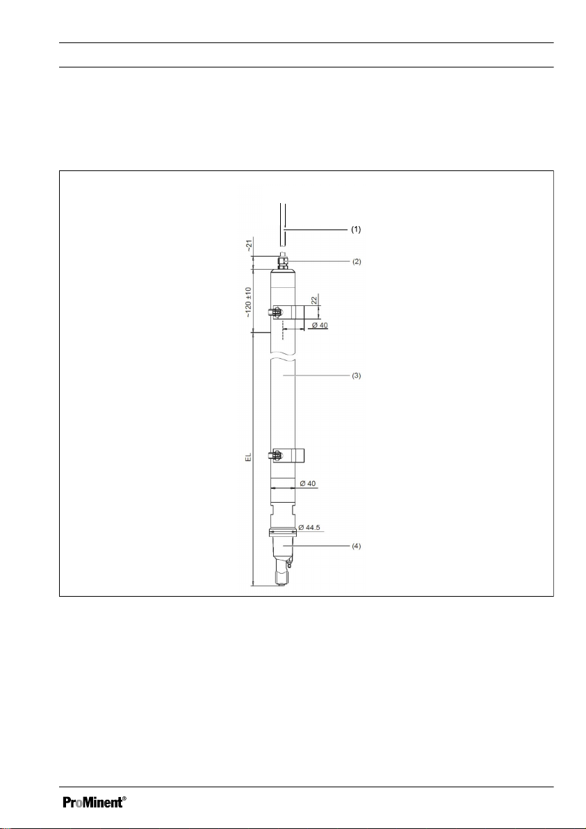
Sensor type ICT5-IMA
The sensor type ICT5-IMA is immersed by the fully assembled immersion tube (1 m) in the storage
tank and channel.
Fig. 3: Sensor type ICT 5-IMA
1. Fixed cable, 10 m
2. Threaded connector M16, degree of protec‐
tion, IP68 (up to 0.2 m)
3. PP
4. PP
11
Page 12
A2637
A2638
Introduction
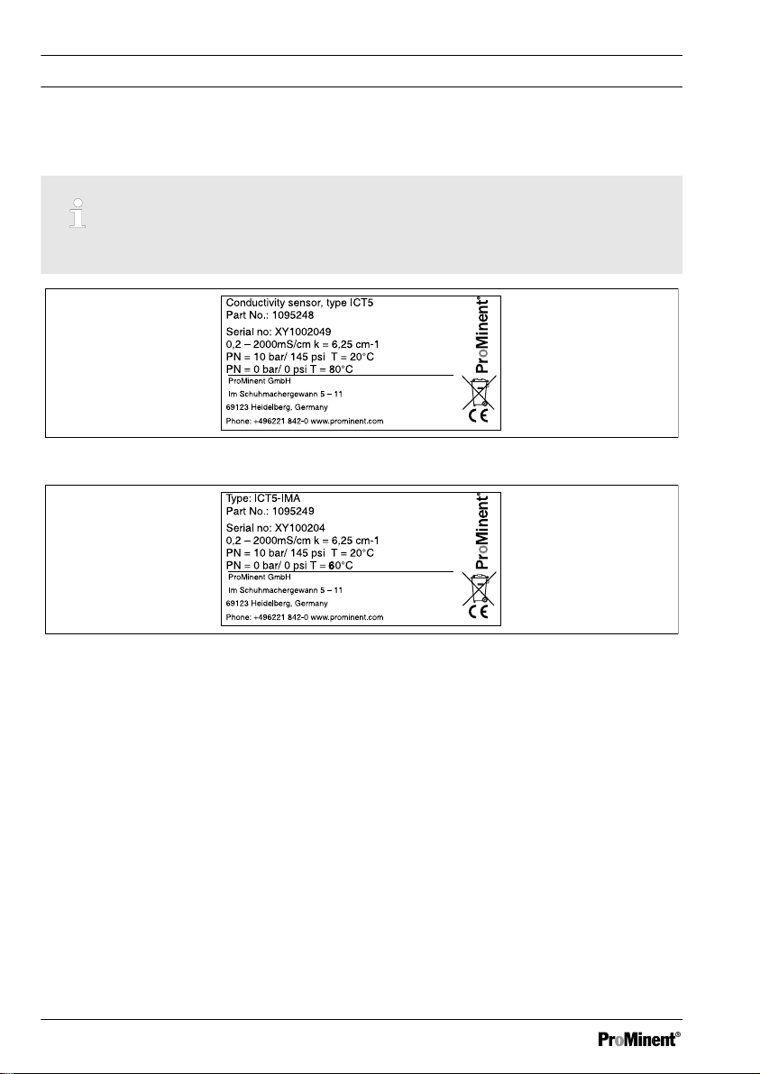
1.3 Nameplate
The cell constant K is needed for calibration on the transmitter/controller.
Fig. 4: ICT5 nameplate
Fig. 5: ICT5-IMA nameplate
1.4 Scope of delivery
Scope of delivery of sensor type ICT 5:
n Sensor type ICT 5, order number 1095248
n Straight solvent union PVC for adaptation
of the sensor to a standard T-piece DN40,
PVC (T-piece not included in the scope of
delivery)
n Assembly and operating instructions
Scope of delivery of sensor type ICT 5-IMA:
n Sensor type ICT 5-IMA, order number
1095249
n Assembly and operating instructions
12
Page 13
2 Safety and responsibility
2.1 Labelling of Warning Infor‐
mation
Introduction
These operating instructions provide informa‐
tion on the technical data and functions of the
product. These operating instructions provide
detailed warning information and are provided
as clear step-by-step instructions.
The warning information and notes are categor‐
ised according to the following scheme. A
number of different symbols are used to denote
different situations. The symbols shown here
serve only as examples.
Safety and responsibility
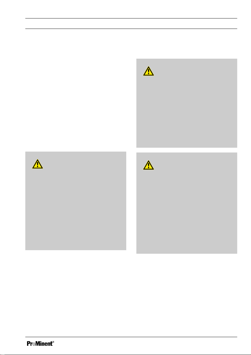
WARNING!
Nature and source of the danger
Possible consequence: Fatal or very
serious injuries.
Measure to be taken to avoid this
danger.
– Denotes a possibly hazardous sit‐
uation. If the situation is disre‐
garded, it could result in fatal or
very serious injuries.
DANGER!
Nature and source of the danger
Consequence: Fatal or very serious
injuries.
Measure to be taken to avoid this
danger.
Description of hazard
– Denotes an immediate threatening
danger. If the situation is disre‐
garded, it will result in fatal or very
serious injuries.
CAUTION!
Nature and source of the danger
Possible consequence: Slight or minor
injuries. Material damage.
Measure to be taken to avoid this
danger.
– Denotes a possibly hazardous sit‐
uation. If the situation is disre‐
garded, it could result in slight or
minor injuries. May also be used
as a warning about material
damage.
13
Page 14

Safety and responsibility
NOTICE!
Nature and source of the danger
Damage to the product or its surround‐
ings.
Measure to be taken to avoid this
danger.
– Denotes a possibly damaging sit‐
uation. If the situation is disre‐
garded, the product or an object in
its vicinity could be damaged.
Type of information
Hints on use and additional information.
Source of the information. Additional
measures.
–
Denotes hints on use and other
useful information. It does not indi‐
cate a hazardous or damaging sit‐
uation.
14
Page 15

Safety and responsibility
2.2 User qualification
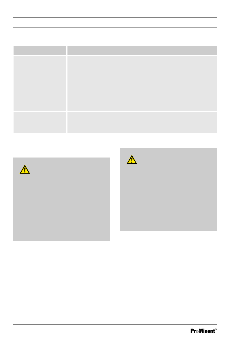
WARNING!
Danger of injury with inadequately qualified personnel
The operator of the system / equipment is responsible for ensuring that the qualifications are
fulfilled.
If inadequately qualified personnel work on the unit or loiter in the hazard zone of the unit,
this could result in dangers that could cause serious injuries and material damage.
– All work on the unit should therefore only be conducted by qualified personnel.
– Unqualified personnel should be kept away from the hazard zone.
The pertinent accident prevention regulations, as well as all other generally acknowledged
safety regulations, must be adhered to.
Training Definition
Instructed personnel An instructed person is deemed to be a person who has been
instructed and, if required, trained in the tasks assigned to him and pos‐
sible dangers that could result from improper behaviour, as well as
having been instructed in the required protective equipment and protec‐
tive measures.
Trained user A trained user is a person who fulfils the requirements made of an
instructed person and who has also received additional training specific
to the system from the manufacturer or another authorised distribution
partner.
Trained, qualified per‐
sonnel
15
A trained, qualified employee is deemed to be a person who is able to
assess the tasks assigned to him and recognize possible hazards
based on his training, knowledge and experience, as well as knowledge
of pertinent regulations. A trained, qualified employee must be able to
perform the tasks assigned to him independently with the assistance of
drawing documentation and parts lists. The assessment of a person's
technical training can also be based on several years of work in the rel‐
evant field.
Page 16
Safety and responsibility
Training Definition
Electrical technician An electrical technician is able to complete work on electrical systems
and recognise and avoid possible dangers independently based on his
technical training and experience as well as knowledge of pertinent
standards and regulations. An electrical technician must be able to per‐
form the tasks assigned to him independently with the assistance of
drawing documentation, parts lists, terminal and circuit diagrams. The
electrical technician must be specifically trained for the working environ‐
ment in which the electrical technician is employed and be conversant
with the relevant standards and regulations.
Service The Service department refers to service technicians, who have
received proven training and have been authorised by the manufacturer
to work on the system.
2.3 General safety information
CAUTION!
WARNING!
Unauthorised access!
Possible consequence: Fatal or very
serious injuries
– Measure: Ensure that there can be
no unauthorised access to the
device
– Only trained personnel may fit,
install, service and operate this
sensor
Functional limitations
Possible consequence: Slight or minor
injuries. Material damage
– Check the sensor regularly for dirt
and contamination
– Observe all applicable national
regulations relating to mainte‐
nance, service and calibration
intervals
16
Page 17

2.4 Intended use
n Only use the sensor to measure and regu‐
late electrolytic conductivity in aqueous
media, which are used in the applications
described in these operating instructions.
n All other uses or modifications are pro‐
hibited.
n The sensor is not a safety component in
the sense of DIN EN ISO
13849-1:2008-12. If there is a critical
process in your measurement and control
circuit, then it is your responsibility to make
sure this process is safe.
2.5 Information in the event of
an emergency
n In the event of an emergency, switch off
the controller
n If liquid escapes from the continuous flow
gauge, close the stopcocks on the inlet
and outlet installed by the customer
n Observe the plant operator's safety infor‐
mation before opening the continuous flow
gauge
Safety and responsibility
17
Page 18

How to store and transport the sensor
3 How to store and transport the sensor
Original packaging
User qualification: instructed user, see
Ä Chapter 2.2 ‘User qualification’ on page 15
Damage to the product.
n Only transport, ship and store the sensor
in its original packaging.
n Retain the packaging in its entirety
including the polystyrene inserts.
3.1 Storage
Storage and transport temperature:
n complete sensor -20 °C ... 75 °C.
Humidity: maximum 90 % relative air humidity,
non-condensing.
Other: No dust, no direct sunlight.
3.2 Transport
The sensor should be transported in its original
packaging and in compliance with the permis‐
sible environmental conditions. No further spe‐
cial conditions have to be observed in relation
to transport.
18
Page 19

4 Assembly and installation
n User qualification, mechanical installation:
trained and qualified personnel
2.2 ‘User qualification’ on page 15
n User qualification, electrical installation:
electrical technician
Ä Chapter 2.2 ‘User
qualification’ on page 15
WARNING!
Danger from hazardous substances!
Possible consequence: Fatal or very
serious injuries.
Please ensure when handling haz‐
ardous substances that you have read
the latest safety data sheets provided
by the manufacture of the hazardous
substance. The actions required are
described in the safety data sheet.
Check the safety data sheet regularly
and replace, if necessary, as the
hazard potential of a substance can be
re-evaluated at any time based on new
findings.
The system operator is responsible for
ensuring that these safety data sheets
are available and that they are kept up
to date, as well as for producing an
associated hazard assessment for the
workstations affected.
Ä Chapter
Assembly and installation
Make sure that the medium flows correctly
through and around the sensor.
Maintain a minimum distance of 20 mm from
the sensor to the tube wall when installing in
pipework.
Minimum compensation will be achieved with
the “Installation factor” parameter if you cannot
adhere to these minimum spacings.
Provide a representative installation site for typ‐
ical conductivity and/or concentration when
immersing in a tank.
Installation site
Ensure that there is unimpeded access for sub‐
sequent calibration.
The mounting must be secure and low-vibra‐
tion.
Avoid direct sunlight.
19
Page 20

1
1
3
2
A2618
Assembly and installation
4.1 Installation of sensor type ICT 5
Fitting position
You can operate the sensor at any angle (0 ... 360°). The sensor is installed in a DN40 standard Tpiece, as shown in Fig. 6 with regard to its flow and the minimum distances from the walls.
Fig. 6: Fitting position of sensor type ICT5 in the T-piece (DN40)
1 ≧ 20 mm
2 Flow direction
3 Sensor
20
Page 21
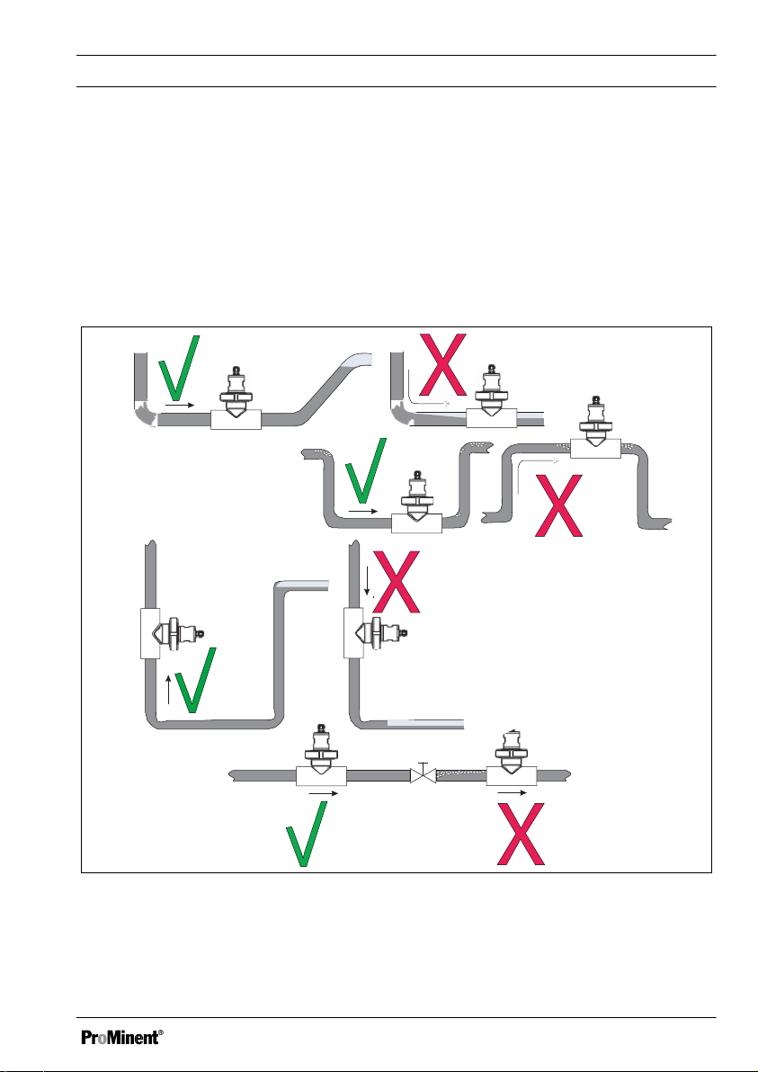
Hydraulic installation situation
A2619
Please note the hydraulic fitting position indicated in Fig. 7.
It is essential that the following are avoided:
n Formation of gas bubbles
n The device running dry
n Stalling
n Turbulence
Assembly and installation
Fig. 7: Hydraulic fitting position / tick = OK, cross = not OK
21
Page 22

A2639
5
4
3
2
1
Assembly and installation
Bonding the straight solvent union into a T-piece
Installing the sensor type ICT5 into PVC pipework. You can install the sensor into a PVC section
using the PVC straight solvent union supplied
Colour Material
Beige PP
Grey PVC
Use suitable adhesive, resistant to the media, for the materials to be bonded.
Fig. 8: Sensor and straight solvent union in a T-piece
1. Bond the straight solvent union (2) supplied into a standard T-piece (3) (on site).
When doing so, adhere to the minimum distances from the walls.
22
Page 23

Assembly and installation
Align the straight solvent union so that the sample medium flows through the sensor eye (5).
Align the guide lip (1) of the adhesive connector towards the T-piece in the flow direction.
Installing the sensor type ICT5 into polypropylene (PP) pipework
2. You can install the sensor directly into an optionally available PP T-piece (order number
1096349, not included in the scope of delivery). The PP T-piece already includes the sensor
adapter.
Assembling the sensor into the T-piece
3. Place the sensor (5) into the T-piece so that the groove (4) on the sensor shaft engages with
the guide lip of the sensor adapter.
4. Manually screw the union nut tightly onto the thread of the sensor adapter.
5. Check the leak-tightness.
4.2 Installation of sensor type
ICT 5-IMA
Installation place
The transducer of sensor type ICT 5-IMA is
fully integrated in the immersion pipe. The
immersion pipe can either be connected to a
storage tank or channel using the holes pro‐
vided or using pipe clamps (on site).
Select a suitable installation site for the repre‐
sentative sample measurement.
23
Page 24

Assembly and installation
4.3 Electrical installation
Do not shorten or mechanically damage the connecting cable.
Once connected, calibrate the inductive conductivity and temperature sensor.
Tab. 2: Terminal assignment, Dulcometer Compact
Terminal Function Sensor ICT5 lead colours
X1.1 Transmission coil, signal
X1.2 Transmission coil, signal, earth
X2.1 Receiver coil, signal
X2.2 Receiver coil, signal, earth Cable shield for X2.1, transparent
XE2.2 Earth Complete cable shield, black
XE4.1 Pt100x
XE4 Pt100x
The descriptions of the terminals refer to the ProMinent measuring and control unit, type DCCa. The
information about the colours relates to the leads of the sensor’s fixed data line.
Connect the data line to the terminals of your ProMinent measuring and control unit, type DCCa. In
doing so, refer to the relevant operating instructions
Connect the data line to the terminals of your measuring/control unit. Refer to the operating
instructions for your measuring/control unit
[bn]
[wh]
[pk]
[gn]
[ye]
, brown
, white
, pink
green
yellow
24
Page 25

Assembly and installation
Tab. 3: General assignment for further measuring/control units
Function Sensor ICT5 lead colours
Transmission coil, signal
Transmission coil, signal, earth
Receiver coil, signal
Receiver coil, signal, earth Cable shield for X2.1, transparent
Earth Complete cable shield, black
Pt100x
Pt100x
Connect the data line to the terminals of your measuring/control unit. Refer to the operating
instructions for your measuring/control unit
[bn]
[wh]
[pk]
[gn]
[ye]
, brown
, white
, pink
green
yellow
25
Page 26

Maintenance
5 Maintenance
WARNING!
Danger from hazardous substances!
Possible consequence: Fatal or very
serious injuries.
Please ensure when handling haz‐
ardous substances that you have read
the latest safety data sheets provided
by the manufacture of the hazardous
substance. The actions required are
described in the safety data sheet.
Check the safety data sheet regularly
and replace, if necessary, as the
hazard potential of a substance can be
re-evaluated at any time based on new
findings.
The system operator is responsible for
ensuring that these safety data sheets
are available and that they are kept up
to date, as well as for producing an
associated hazard assessment for the
workstations affected.
3. Check the complete measuring chain
(sensor, connecting line and transmitter/
controller) should there be deviations of
the measured values with an unknown
cause.
NOTICE!
Solvent
Only use water rather than a volatile
organic solvent to clean the sensor.
1. Clean the sensor with water and a soft
brush.
2. Loosen tough films or deposits with
diluted hydrochloric acid and remove
with a soft brush.
26
Page 27

Rectifying faults and malfunctions
6 Rectifying faults and malfunctions
Problem Possible cause Measure
No display of measured value
or signal output
Display of measured value is
000 or signal output is 0% (e.g.
4 mA)
Incorrect or fluctuating meas‐
ured value display
No power supply Check power supply, check
terminals
Sensor not immersed in the
medium; storage tank level too
low
Flow fitting blocked Clean flow fitting
Sensor faulty
Sensor not immersed deeply
enough
No mixing Ensure that the sample is
Air bubbles Refer to the installation instruc‐
Top up storage tank
Top up storage tank
mixed well, ensuring that there
is approx. 18 mm of free circu‐
lation on all sides of the sensor
tions
27
Page 28

Disposal of used parts
7 Disposal of used parts
n User qualification: instructed user, see
Ä Chapter 2.2 ‘User qualification’
on page 15
NOTICE!
Regulations governing the disposal of
used parts
– Note the national regulations and
legal standards that currently
apply in your country
The manufacturer will take back decontami‐
nated used devices providing they are covered
by adequate postage.
Decontaminate the device before returning it for
repair. To do so, remove all traces of haz‐
ardous substances. Refer to the Material Safety
Data Sheet for your feed chemical.
A current Declaration of Decontamination is
available to download on the ProMinent web‐
site.
Sign indicating EU collection system
In accordance with the European Directive
2012/19/EU on waste electrical and electronic
equipment, this device features the symbol
showing a waste bin with a line through it. The
device must not be disposed of along with
domestic waste. To return the device, use the
return and collection systems available and
observe the local legal requirements.
28
Page 29

Accessories
8 Accessories
Description Part
number
Straight solvent union (PVC) + O-ring, for installation of sensor type ICT5 into a PVC
T-piece DN40
Union nut G 1 1/2”, PVC 1096351
T-piece, PP, DN40 with integral sensor adapter* 1096349
Union nut G 1 1/2”, PP 1096353
* Features an anti-turn locking device; the sensor can only be installed in the right direction.
1096348
29
Page 30

Technical data
9 Technical data
9.1 General data
Parameter ICT 5 ICT 5-IMA
Design For operation in the flow For immersion
Measuring principle inductive
Measuring range 0 ... 2000 mS/cm
Precision within the measuring range
0 ... 1 mS/cm ≤ 1%
0 ... 10 mS/cm ≤ 0.5%
0 ... 50 mS/cm ≤ 0.5%
0 ... 100 mS/cm ≤ 0.5%
0 ... 1000 mS/cm ≤ 1%
0 ... 2000 mS/cm ≤ 1%
Cell constant k = 6.25 1/cm
Temperature sensor Pt1000, Class A
t90 Temperature
Permissible ambient temperature -10 ... +60 °C
Permissible storage temperature -20 ... +75 °C
Degree of protection
Permitted medium temperature
when operating in pipework made
of:
Maximum process pressure with PP design
at 20 °C 10 bar 0 bar
at 60 °C 6 bar 0 bar
at 80 °C 0 bar
a
b
PVC: -10 ... +60 °C
PP: -10 ... +80 °C
≤ 6 seconds
IP68
-10 ... +60 °C
30
Page 31

Technical data
Parameter ICT 5 ICT 5-IMA
at -10 ... +80 °C minimum -0.1 bar minimum -0.1 bar
Sensor material, wetted
Sensor body PP
Protective sleeve, temperature
Stainless steel 1.4571
sensor
Seal EPDM
Electrical connection Fixed cable, 10 m, PUR, lead
Threaded cable connector M16, PBT/PA
Length of immersion fitting 1000 mm
a
DIN EN 60751
b
DIN EN 60529
9.2 Certification/Test marks
The materials wetted by the sample medium
are approved for use with food, physiologically
harmless and listed by the FDA.
31
Page 32

0
8
0
4
2
10
50403020
10
0-10 60 70 80
I
II
A2624
Technical data
9.3 Permitted process pressure
Temperature, pressure and the sample medium have an impact on the service life of the sensor.
Fig. 9: Permitted process pressure type ICT 5 fitted in PP pipework
I Pressure in bar.
II Temperature in °C.
32
Page 33

10 Dimensions
I. II. III. IV.
Ø40
Ø44,5
Ø40
22
21
120 ± 10
EL
A2620
Fig. 10: Dimensions, all dimensions in mm. Type ICT 5-IMA... Immersion version
I Fixed cable, 10 m
II Threaded connector M16, degree of protec‐
tion IP68 (up to 0.2 m), PBT/PA
III PP
IV Stainless steel 1.4301, AISI 304
Dimensions
33
Page 34

I.
II.
145
~81
118
36,5
A2622
Ø41
Ø44,5
67
Dimensions
Fig. 11: Dimensions, all dimensions in mm. Type ICT 5
I Threaded connector M16, degree of protec‐
tion IP68 (up to 0.2 m), PBT/PA
II PP
34
Page 35

ProMinent GmbH
Im Schuhmachergewann 5 - 11
69123 Heidelberg
Telephone: +49 6221 842-0
Fax: +49 6221 842-419
Email: info@prominent.com
Internet: www.prominent.com
982358, 1, en_GB
© 2018
Page 36

Montage- und Betriebsanleitung
A2632
DULCOTEST® Sensor ICT 5 und ICT 5-IMA
Sensor für elektrolytische Leitfähigkeit
DE
Betriebsanleitung bitte zuerst vollständig durchlesen. · Nicht wegwerfen.
Bei Schäden durch Installations- oder Bedienfehler haftet der Betreiber.
Die neueste Version einer Betriebsanleitung ist auf unserer Homepage verfügbar.
982358 BA DT 157 10/18 DE
Page 37

Ergänzende Anweisungen
Allgemeine Gleichbehandlung Dieses Dokument verwendet die nach der
Grammatik männliche Form in einem neutralen
Sinn, um den Text leichter lesbar zu halten. Es
spricht immer Frauen und Männer in gleicher
Weise an. Die Leserinnen bitten wir um Ver‐
ständnis für diese Vereinfachung im Text.
Ergänzende Anweisungen
Lesen Sie bitte die ergänzenden Anweisungen durch.
Infos
Eine Info gibt wichtige Hinweise für das richtige Funktionieren des Geräts oder soll Ihre
Arbeit erleichtern.
Warnhinweise
Warnhinweise sind mit ausführlichen Beschreibungen der Gefährdungssituation versehen, siehe
Ä Kapitel 2.1 „Kennzeichnung der Warnhinweise“ auf Seite 45
Zur Hervorhebung von Handlungsanweisungen, Verweisen, Auflistungen, Ergebnissen und anderen
Elementen können in diesem Dokument folgende Kennzeichnungen verwendet werden:
.
Tab. 1: Weitere Kennzeichnung
Kennzeichen Beschreibung
Handlung Schritt-für-Schritt.
⇨ Ergebnis einer Handlung.
Links auf Elemente bzw. Abschnitte dieser Anleitung oder mitgeltende Doku‐
mente.
n
[Taster]
37
Auflistung ohne festgelegte Reihenfolge.
Anzeigeelemente (z. B. Signalleuchten).
Bedienelemente (z. B. Taster, Schalter).
Page 38

Ergänzende Anweisungen
Kennzeichen Beschreibung
„Anzeige/GUI“
CODE
Bildschirmelemente (z. B. Schaltflächen, Belegung von Funktionstasten).
Darstellung von Softwareelementen bzw. Texten.
38
Page 39

Inhaltsverzeichnis
Inhaltsverzeichnis
1 Einleitung.............................................................................................................................. 40
1.1 Messprinzip.................................................................................................................. 40
1.2 Aufbau und Funktion des Sensors............................................................................... 41
1.3 Typenschild.................................................................................................................. 44
1.4 Lieferumfang................................................................................................................ 44
2 Sicherheit und Verantwortung............................................................................................... 45
2.1 Kennzeichnung der Warnhinweise............................................................................... 45
2.2 Benutzer-Qualifikation.................................................................................................. 47
2.3 Allgemeine Sicherheitshinweise................................................................................... 48
2.4 Bestimmungsgemäße Verwendung............................................................................. 49
2.5 Angaben für den Notfall................................................................................................ 49
3 So lagern und transportieren Sie den Sensor....................................................................... 50
3.1 Lagerung...................................................................................................................... 50
3.2 Transport...................................................................................................................... 50
4 Montage und Installation....................................................................................................... 51
4.1 Montage des Sensortyps ICT 5.................................................................................... 52
4.2 Montage des Sensortyps ICT 5-IMA............................................................................ 55
4.3 Elektrische Installation.................................................................................................. 56
5 Wartung................................................................................................................................. 58
6 Fehler und Störungen beheben............................................................................................ 59
7 Altteileentsorgung................................................................................................................. 60
8 Zubehör................................................................................................................................. 61
9 Technische Daten................................................................................................................. 62
9.1 Allgemeine Daten......................................................................................................... 62
9.2 Zulassungen/Prüfzeichen............................................................................................. 63
9.3 Zulässiger Prozessdruck.............................................................................................. 64
10 Abmessungen....................................................................................................................... 65
39
Page 40

Einleitung
1 Einleitung
Diese Betriebsanleitung beschreibt die techni‐
schen Daten und Funktionen des
DULCOTEST® Sensors für Induktive Leitfähig‐
keit, ICT 5 und ICT-IMA.
Der Typ ICT 5 ist für den Durchflussbetrieb
ausgelegt.
Der Typ ICT 5-IMA ist in ein Eintauchrohr integ‐
riert, für das Eintauchen im Behälter und im
offenen Gerinne.
Der Sensor erfasst online die elektrolytische
Leitfähigkeit einer wässrigen Prozessflüssig‐
keit. Beide Sensortypen arbeiten nach dem
induktiven Messprinzip. Durch das induktive
Messverfahren ist der Sensor nahezu war‐
tungsfrei. Feste Ablagerungen und Fett- oder
Ölfilme auf der Sensoroberfläche haben kaum
Einfluss auf die Messgenauigkeit. Der Sensor
sind insbesondere zum Messen von hohen
Leitfähigkeiten bis 2000 mS/cm geeignet. Ein
freistehender Temperatursensor (Pt1000) mit
kurzer Ansprechzeit erfasst die Prozesstempe‐
ratur. Der Temperatursensor ist in einer Edel‐
stahlhülse geschützt. Durch den Temperatur‐
sensor (Pt1000) kann die Temperaturkorrektur
der Leitfähigkeitsmessung im angeschlossenen
Mess- und Regelgerät erfolgen.
Sie können die beiden Sensortypen auch in
verschmutzten Wässern oder in aggressiven
Medien einsetzen die sich gegenüber PVC/
EPDM bzw. PP/EPDM (ja nach Ausführung des
Sensors) chemisch inert verhalten.
1.1 Messprinzip
Die Messung der elektrolytischen Leitfähigkeit
erfolgt mit einen induktiven Sensor. Der Sensor
enthält im Sensorkopf eine Sende- und Emp‐
fangsspule. Eine Sinus-Wechselspannung
speist die Sendespule. In Abhängigkeit von der
Leitfähigkeit der zu messenden Flüssigkeit wird
ein Messstrom in die Empfangsspule induziert.
Der Messstrom ist proportional zur Leitfähigkeit
des Mediums.
Typische Anwendungsgebiete
Der Sensor ist vornehmlich für die Anwendung
in der Wasseraufbereitung und zur Wasserü‐
berwachung konzipiert, z. B.:
n verschmutzte Ab- und Brauchwasser
n Klima- und Kühlanlagen
n Absalzkontrolle in Kühltürmen,
n Spülbäder,
n Fahrzeugwaschanlagen,
n Meerwasserentsalzung (Zulauf),
n Schwimmbadwasserkontrolle.
40
Page 41

A2617
4
3
2
1
5
Einleitung
1.2 Aufbau und Funktion des Sensors
Der induktive Messwertaufnehmer der beiden Sensortypen ICT 5 und ICT 5-IMA besteht aus einem
hermetisch verschlossenen Körper aus Polypropylen (PP). Im Innerem des Messwertaufnehmers
befindet sich eine Sende- und eine Empfängerspule. Eine Durchflussöffnung in dem Sensor (Sen‐
sorauge) erlaubt die Durchströmung mit dem Messmedium. Bedingt durch das Messprinzip besteht
eine galvanische Trennung zwischen Messmedium und Signalausgang. Ein freistehender Tempera‐
tursensor (Pt1000) mit kurzer Ansprechzeit erfasst die Prozesstemperatur. Der Temperatursensor
ist in einer schützenden Edelstahlhülse integriert.
Abb. 1: Bauteile
1 Sensorkörper aus PP
2 Sendespule
3 Sensorauge, durchströmt vom Messme‐
dium
4 Empfängerspule
5 Temperatursensor, freistehend, integriert in
eine Edelstahlhülse
41
Page 42

A2641
Einleitung
Sensortyp ICT 5
Der Sensortyp ICT5 wird über eine Gewindebuchse und Überwurfmutter an ein Standard T-Stück
DN40 (bauseits) zum Betrieb im Durchfluss angebunden.
Abb. 2: Sensortyp ICT 5
1. Gewindebuchse G 1 1/2“ (PVC bzw.PP)
2. Überwurfmutter (PVC bzw. PP)
42
Page 43

A2642
Einleitung
Sensortyp ICT5-IMA
Der Sensortyp ICT5-IMA wird über das komplett montierte Tauchrohr (1 m) in Behälter und in
Gerinne eingetaucht.
Abb. 3: Sensortyp ICT 5-IMA
1. Festkabel, 10 m
2. Kabelverschraubung M16, Schutzart IP68
(bis 0,2 m)
3. PP
4. PP
43
Page 44

A2637
A2638
Einleitung
1.3 Typenschild
Die Zellenkonstante K wird für die Kalibrierung am Messumformer/Regler benötigt.
Abb. 4: Typenschild ICT5
Abb. 5: Typenschild ICT5-IMA
1.4 Lieferumfang
Lieferumfang Sensortyp ICT 5:
n Sensor Typ ICT 5, Bestellnummer
1095248
n Klebemuffe PVC zur Adaption des Sen‐
sors, an ein Standard-T-Stück DN40, PVC
(T-Stück nicht im Lieferumfang enthalten)
n Montage- und Betriebsanleitung
Lieferumfang Sensortyp ICT 5-IMA:
n Sensor Typ ICT 5-IMA, Bestellnummer
1095249
n Montage- und Betriebsanleitung
44
Page 45

2 Sicherheit und Verantwortung
2.1 Kennzeichnung der Warn‐
hinweise
Einleitung
Diese Betriebsanleitung beschreibt die techni‐
schen Daten und Funktionen des Produktes.
Die Betriebsanleitung gibt ausführliche Warn‐
hinweise und ist in klare Handlungsschritte auf‐
gegliedert.
Warnhinweise und Hinweise gliedern sich nach
dem folgenden Schema. Hierbei kommen ver‐
schiedene, der Situation angepasste, Piktogr‐
amme zum Einsatz. Die hier aufgeführten Pik‐
togramme dienen nur als Beispiel.
GEFAHR!
Art und Quelle der Gefahr
Folge: Tod oder schwerste Verlet‐
zungen.
Maßnahme, die ergriffen werden muss,
um diese Gefahr zu vermeiden.
Beschriebene Gefahr
– Bezeichnet eine unmittelbar dro‐
hende Gefahr. Wenn die Situation
nicht gemieden wird, sind Tod
oder schwerste Verletzungen die
Folge.
Sicherheit und Verantwortung
WARNUNG!
Art und Quelle der Gefahr
Mögliche Folge: Tod oder schwerste
Verletzungen.
Maßnahme, die ergriffen werden muss,
um diese Gefahr zu vermeiden.
– Bezeichnet eine möglicherweise
gefährliche Situation. Wenn die
Situation nicht gemieden wird,
können Tod oder schwerste Ver‐
letzungen die Folge sein.
VORSICHT!
Art und Quelle der Gefahr
Mögliche Folge: Leichte oder geringfü‐
gige Verletzungen. Sachbeschädigung.
Maßnahme, die ergriffen werden muss,
um diese Gefahr zu vermeiden.
– Bezeichnet eine möglicherweise
gefährliche Situation. Wenn die
Situation nicht gemieden wird,
können leichte oder geringfügige
Verletzungen die Folge sein. Darf
auch für Warnung vor Sach‐
schäden verwendet werden.
45
Page 46

Sicherheit und Verantwortung
HINWEIS!
Art und Quelle der Gefahr
Schädigung des Produkts oder seiner
Umgebung.
Maßnahme, die ergriffen werden muss,
um diese Gefahr zu vermeiden.
– Bezeichnet eine möglicherweise
schädliche Situation. Wenn die
Situation nicht gemieden wird,
kann das Produkt oder etwas in
seiner Umgebung beschädigt
werden.
Art der Information
Anwendungstipps und Zusatzinforma‐
tion.
Quelle der Information. Zusätzliche
Maßnahmen.
–
Bezeichnen Anwendungstipps und
andere besonders nützliche Infor‐
mationen. Es ist kein Signalwort
für eine gefährliche oder schäd‐
liche Situation.
46
Page 47

Sicherheit und Verantwortung
2.2 Benutzer-Qualifikation
WARNUNG!
Verletzungsgefahr bei unzureichender Qualifikation des Personals
Der Betreiber der Anlage/des Gerätes ist für die Einhaltung der Qualifikationen verantwort‐
lich.
Wenn unqualifiziertes Personal Arbeiten an dem Gerät vornimmt oder sich im Gefahrenbe‐
reich des Gerätes aufhält, entstehen Gefahren, die schwere Verletzungen und Sachschäden
verursachen können.
– Alle Tätigkeiten nur durch dafür qualifiziertes Personal durchführen lassen.
– Unqualifiziertes Personal von den Gefahrenbereichen fernhalten.
Die einschlägigen Unfallverhütungsvorschriften sowie die sonstigen allgemein anerkannten
sicherheitstechnischen Regeln einhalten.
Ausbildung Definition
unterwiesene Person Als unterwiesene Person gilt, wer über die übertragenen Aufgaben und
möglichen Gefahren bei unsachgemäßem Verhalten unterrichtet und
erforderlichenfalls angelernt, sowie über die notwendigen Schutzein‐
richtungen und Schutzmaßnahmen belehrt wurde.
geschulter Anwender Als geschulter Anwender gilt, wer die Anforderungen an eine unterwie‐
sene Person erfüllt und zusätzlich eine anlagenspezifische Schulung
bei dem Hersteller oder einem autorisierten Vertriebspartner erhalten
hat.
ausgebildete Fachkraft Als ausgebildete Fachkraft gilt, wer aufgrund seiner Ausbildung, Kennt‐
nisse und Erfahrungen sowie Kenntnis der einschlägigen Bestim‐
mungen die ihm übertragenen Arbeiten beurteilen und mögliche
Gefahren erkennen kann. Eine ausgebildete Fachkraft muss in der
Lage sein, die ihr übertragenen Arbeiten unter Zuhilfenahme von Zeich‐
nungsdokumentation und Stücklisten selbständig durchzuführen. Zur
Beurteilung der fachlichen Ausbildung kann auch eine mehrjährige
Tätigkeit auf dem betreffenden Arbeitsgebiet herangezogen werden.
47
Page 48

Sicherheit und Verantwortung
Ausbildung Definition
Elektrofachkraft Die Elektrofachkraft ist aufgrund ihrer fachlichen Ausbildung, Kennt‐
nisse und Erfahrungen sowie Kenntnis der einschlägigen Normen und
Bestimmungen in der Lage, Arbeiten an elektrischen Anlagen auszu‐
führen und mögliche Gefahren selbstständig zu erkennen und zu ver‐
meiden. Eine Elektrofachkraft muss in der Lage sein, die ihr übertra‐
genen Arbeiten unter Zuhilfenahme von Zeichnungsdokumentation,
Stücklisten, Klemmen- und Schaltplänen selbständig durchzuführen.
Die Elektrofachkraft ist speziell für das Arbeitsumfeld, in dem die Elekt‐
rofachkraft tätig ist, ausgebildet und kennt die relevanten Normen und
Bestimmungen.
Kundendienst Als Kundendienst gelten Servicetechniker, die von dem Hersteller für
die Arbeiten an der Anlage nachweislich geschult und autorisiert
wurden.
2.3 Allgemeine Sicherheitshin‐
weise
WARNUNG!
Unbefugter Zugriff!
Mögliche Folge: Tod oder schwerste
Verletzungen
– Maßnahme: Sichern Sie das Gerät
gegen unbefugten Zugriff
– Der Sensor darf nur durch hierfür
ausgebildetes Personal montiert,
installiert, gewartet und betrieben
werden
VORSICHT!
Funktionseinschränkung
Mögliche Folge: Leichte oder geringfü‐
gige Verletzungen. Sachbeschädigung
– Den Sensor regelmäßig auf Ver‐
unreinigungen überprüfen
– Die gültigen nationalen Vor‐
schriften für Pflege-, Wartungsund Kalibrierintervalle einhalten
48
Page 49

2.4 Bestimmungsgemäße Ver‐
wendung
n Der Sensor darf nur zum Messen und
Regeln der elektrolytischen Leitfähigkeit in
wässrigen Medien, der in dieser Betriebs‐
anleitung beschriebenen Anwendungen
verwendet werden.
n Alle anderen Verwendungen oder ein
Umbau sind verboten.
n Der Sensor ist kein Sicherheitsbauteil im
Sinne der DIN EN ISO 13849-1:2008-12.
Sollte es sich bei Ihren Mess- und Regel‐
kreis um einen kritischen Prozess handeln,
dann liegt es in Ihrer Verantwortung
diesen Prozess abzusichern.
2.5 Angaben für den Notfall
n Im Notfall den Regler spannungsfrei
machen
n Falls aus der Durchlaufarmatur Flüssigkeit
austritt, die bauseitig installierten Absperr‐
hähne am Zu- und Ablauf schließen
n Vor dem Öffnen der Durchlaufarmatur die
Sicherheitshinweise des Anlagenbetrei‐
bers beachten
Sicherheit und Verantwortung
49
Page 50

So lagern und transportieren Sie den Sensor
3 So lagern und transportieren Sie den Sensor
Originalverpackung
Benutzer-Qualifikation: unterwiesene Person,
siehe
Ä Kapitel 2.2 „Benutzer-Qualifikation“
auf Seite 47
Schädigung des Produkts.
n Transportieren, versenden und lagern Sie
den Sensor nur in der Originalverpackung.
n Bewahren Sie die Verpackung komplett
mit den Styroporteilen auf.
3.1 Lagerung
Lager- und Transporttemperatur:
n kompletter Sensor -20 °C ... 75 °C.
Feuchtigkeit: maximal 90 % relative Luftfeuch‐
tigkeit, nicht kondensierend.
Sonstige: Kein Staub, kein direktes Sonnen‐
licht.
3.2 Transport
Der Transport sollte in der Originalverpackung
und innerhalb der zulässigen Umweltbedin‐
gungen erfolgen. Weitere Besonderheiten sind
beim Transport nicht zu beachten.
50
Page 51

4 Montage und Installation
n Benutzer-Qualifikation, mechanische Mon‐
tage: ausgebildete Fachkraft
„Benutzer-Qualifikation“ auf Seite 47
n Benutzer-Qualifikation, elektrische Installa‐
tion: Elektrofachkraft
„Benutzer-Qualifikation“ auf Seite 47
WARNUNG!
Gefährdung durch einen Gefahrstoff!
Mögliche Folge: Tod oder schwerste
Verletzungen.
Beachten Sie beim Umgang mit
Gefahrstoffen, dass die aktuellen
Sicherheitsdatenblätter der GefahrstoffHersteller vorliegen. Die notwendigen
Maßnahmen ergeben sich aus dem
Inhalt des Sicherheitsdatenblatts. Da
aufgrund neuer Erkenntnisse, das
Gefährdungspotenzial eines Stoffes
jederzeit neu bewertet werden kann, ist
das Sicherheitsdatenblatt regelmäßig
zu überprüfen und bei Bedarf zu
ersetzen.
Für das Vorhandensein und den aktu‐
ellen Stand des Sicherheitsdatenblatts
und die damit verbundene Erstellung
der Gefährdungsbeurteilung der betrof‐
fenen Arbeitsplätze ist der Anlagenbe‐
treiber verantwortlich.
Ä Kapitel 2.2
Ä Kapitel 2.2
Montage und Installation
Achten Sie auf eine gute Durch- und Umströ‐
mung des Sensors.
Halten Sie beim Einbau in eine Rohrleitung
einen Mindestabstand von 20 mm vom Sensor
zur Rohrwandung ein.
Wenn Sie diese Mindestabstände nicht ein‐
halten können, dann kann mit dem Parameter
„Einbaufaktor“ ein begrenzter Ausgleich
erreicht werden.
Beim Eintauchbetrieb in Becken müssen Sie
einen für die typische Leitfähigkeit bzw. Kon‐
zentration repräsentativen Einbauort vorsehen.
Montageort
Achten Sie auf eine leichte Zugänglichkeit für
die spätere Kalibrierung.
Die Befestigung muss sicher und vibrationsarm
sein.
Vermeiden Sie direkte Sonneneinstrahlung.
51
Page 52

1
1
3
2
A2618
Montage und Installation
4.1 Montage des Sensortyps ICT 5
Einbaulage
Sie können den Sensor in jeder Winkelorientierung (0 ... 360°) betreiben. Der Sensor wird bezüglich
seiner Anströmung und den Mindestabständen von Wandungen, wie in Abb. 6 gezeigt, in ein DN40
Standard-T-Stück eingebaut.
Abb. 6: Einbaulage des Sensorstyps ICT5 im T Stück (DN40)
1 ≧ 20 mm
2 Strömungsrichtung
3 Sensor
52
Page 53

Hydraulische Einbausituation
A2619
Beachten Sie die in Abb. 7 gezeigte hydraulische Einbausituation.
Unbedingt vermeiden:
n Bildung von Gasblasen
n Trockenlaufen
n Strömungsabrisse
n Verwirbelungen
Montage und Installation
Abb. 7: Hydraulische Einbausituation / Haken = OK, Kreuz = NOK
53
Page 54

A2639
5
4
3
2
1
Montage und Installation
Einkleben der Klebemuffe in ein T-Stück
Montage des Sensortyps ICT5 in einer Verrohrung aus PVC. Sie können den Sensor in ein PVC-TStück einbauen, unter Verwendung der mitgelieferten PVC-Klebemuffe
Farbe Material
Beige PP
Grau PVC
Verwenden Sie für die zu verklebenden Materialien geeignete und medienbeständige Kleber.
Abb. 8: Sensor und Klebemuffe in Standard-T-Stück
1. Kleben Sie die beiliegende Klebemuffe (2) in ein Standard-T-Stück (3) (bauseits) ein.
Halten Sie dazu den Mindestabstand zu den Wandungen ein.
54
Page 55

Montage und Installation
Richten Sie dazu die Klebemuffe so aus, dass das Messmedium durch das Sensorauge (5)
fließt.
Richten Sie dazu die Führungszapfen (1) des Klebestutzens in Durchflussrichtung zum TStück aus.
Montage des Sensortyps ICT5 in einer Verrohrung aus Polypropylen (PP)
2. Sie können den Sensor direkt in das optional erhältliche PP-T-Stück einbauen (Bestell‐
nummer 1096349, nicht im Lieferumfang). Das PP-T-Stück enthält bereits den Sensora‐
dapter.
Montage des Sensors in das T-Stück
3. Setzen Sie den Sensor (5) so in das T-Stück ein, dass die Nut (4) am Sensorschaft in den
Führungszapfen des Sensoradapters greift.
4. Schrauben Sie die Überwurfmutter per Hand fest auf das Gewinde des Sensoradapters auf.
5. Überprüfen Sie die Dichtigkeit.
4.2 Montage des Sensortyps ICT 5-IMA
Einbauort
Der Messwertaufnehmer des Sensortyps ICT
5-IMA ist vollständig in das Eintauchrohr integ‐
riert. Das Eintauchrohr kann entweder über die
vorhandenen Bohrungen oder mit Rohrschellen
(bauseits) an einen Behälter oder an ein
Gerinne angebunden werden.
Wählen Sie einen für die repräsentative Probe‐
messung einen geeigneten Installationspunkt.
55
Page 56

Montage und Installation
4.3 Elektrische Installation
Sie dürfen das Anschlusskabel nicht kürzen oder mechanisch beschädigen.
Nach dem Anschluss müssen Sie den induktiven Leitfähigkeits- und Temperatursensor
kalibrieren.
Tab. 2: Klemmenzuordnung, Dulcometer Compact
Klemme Funktion Sensor ICT5 Leiterfarben
X1.1 Sendespule, Signal
X1.2 Sendespule, Signal, Erde
X2.1 Empfangsspule, Signal
X2.2 Empfangsspule, Signal, Erde Kabelabschirmung für X2.1, trans‐
XE2.2 Masse Kabelabschirmung gesamt,
XE4.1 Pt100x
XE4 Pt100x
Die Bezeichnungen der Klemmen beziehen sich auf das ProMinent-Mess-/Regelgerät, Typ DCCa.
Die Angaben der Farben beziehen sich auf die Adern der fest installierten Datenleitung des Sen‐
sors.
Verbinden Sie die Datenleitung mit den Klemmen Ihres ProMinent-Mess-/Regelgerät, Typ DCCa.
Beachten Sie hierbei die entsprechende Betriebsanleitung
Verbinden Sie die Datenleitung mit den Klemmen Ihres Mess-/Regelgerätes. Beachten Sie
hierbei die Betriebsanleitung Ihres Mess-/Regelgerätes
[bn]
, Braun
[ws]
, Weiß
[pk]
, Pink
parent
schwarz
[gn]
Grün
[ge]
Gelb
56
Page 57

Montage und Installation
Tab. 3: Allgemeine Zuordnung für weitere Mess-/Regelgeräte
Funktion Sensor ICT5 Leiterfarben
Sendespule, Signal
Sendespule, Signal, Erde
Empfangsspule, Signal
Empfangsspule, Signal, Erde Kabelabschirmung für X2.1, transparent
Masse Kabelabschirmung gesamt, schwarz
Pt100x
Pt100x
Verbinden Sie die Datenleitung mit den Klemmen Ihres Mess-/Regelgerätes. Beachten Sie
hierbei die Betriebsanleitung Ihres Mess-/Regelgerätes
[bn]
[ws]
[pk]
[gn]
[ge]
, Braun
, Weiß
, Pink
Grün
Gelb
57
Page 58

Wartung
5 Wartung
WARNUNG!
Gefährdung durch einen Gefahrstoff!
Mögliche Folge: Tod oder schwerste
Verletzungen.
Beachten Sie beim Umgang mit
Gefahrstoffen, dass die aktuellen
Sicherheitsdatenblätter der GefahrstoffHersteller vorliegen. Die notwendigen
Maßnahmen ergeben sich aus dem
Inhalt des Sicherheitsdatenblatts. Da
aufgrund neuer Erkenntnisse, das
Gefährdungspotenzial eines Stoffes
jederzeit neu bewertet werden kann, ist
das Sicherheitsdatenblatt regelmäßig
zu überprüfen und bei Bedarf zu
ersetzen.
Für das Vorhandensein und den aktu‐
ellen Stand des Sicherheitsdatenblatts
und die damit verbundene Erstellung
der Gefährdungsbeurteilung der betrof‐
fenen Arbeitsplätze ist der Anlagenbe‐
treiber verantwortlich.
3. Sollten Messwertabweichungen unbe‐
kannter Ursache auftreten, müssen Sie
die komplette Messkette (Sensor,
Anschlussleitung und Messumformer/
Regler) überprüfen,
Ä Kapitel 6 „Fehler
und Störungen beheben“ auf Seite 59
.
HINWEIS!
Lösungsmittel
Verwenden Sie für die Reinigung des
Sensors keine flüchtigen organischen
Lösungsmittel, sondern ausschließlich
Wasser als Lösungsmittel.
1. Reinigen Sie den Sensor mit Wasser
und einer weichen Bürste.
2. Hartnäckige Beläge bzw. Ablagerungen
können Sie z. B. mit verdünnter Salz‐
säure anlösen und mit einer weichen
Bürste entfernen.
58
Page 59

Fehler und Störungen beheben
6 Fehler und Störungen beheben
Problem mögliche Ursache Maßnahme
Keine Messwertanzeige bzw.
Signalausgang
Messwertanzeige 000 bzw.
Signalausgang 0 % (z. B.
4 mA)
Falsche oder schwankende
Messwertanzeige
Spannungsversorgung fehlt Spannungsversorgung prüfen,
Klemmen überprüfen
Sensor nicht in Medium einge‐
taucht; Behälterniveau zu
niedrig
Durchflussarmatur verstopft Durchflussarmatur reinigen
Sensor defekt
Sensor nicht tief genug einge‐
taucht
keine Durchmischung für gute Durchmischung
Luftblasen Einbauhinweise beachten
Behälter auffüllen
Behälter auffüllen
sorgen, beim Sensor auf all‐
seitig ca. 18 mm freie Umspü‐
lung achten
59
Page 60

Altteileentsorgung
7 Altteileentsorgung
n Benutzer-Qualifikation: unterwiesene
Person, siehe
Qualifikation“ auf Seite 47
HINWEIS!
Vorschriften Altteileentsorgung
– Beachten Sie die zurzeit für Sie
gültigen nationalen Vorschriften
und Rechtsnormen
Der Hersteller nimmt die dekontaminierten Alt‐
geräte bei ausreichender Frankierung der Sen‐
dung zurück.
Bevor Sie das Gerät einschicken, müssen Sie
das Gerät dekontaminieren. Dazu müssen Sie
alle Gefahrenstoffe restlos entfernen. Beachten
Sie dazu das Sicherheitsdatenblatt ihres
Dosiermediums.
Eine aktuelle Dekontaminationserklärung steht
als Download auf der Homepage zur Verfü‐
gung.
Ä Kapitel 2.2 „Benutzer-
Hinweis auf Sammelsystem EU
Dieses Gerät ist entsprechend der europä‐
ischen Richtlinie 2012/19/EU über Elektro- und
Elektronik-Altgeräte mit dem Symbol der durch‐
gestrichenen Mülltonne gekennzeichnet. Das
Gerät darf nicht über den Hausmüll entsorgt
werden. Nutzen Sie für die Rückgabe die Ihnen
zur Verfügung stehenden Rückgabe- und Sam‐
melsysteme und beachten Sie die örtlichen
gesetzlichen Vorgaben.
60
Page 61

Zubehör
8 Zubehör
Bezeichnung Teile‐
nummer
Klebemuffe (PVC) + O-Ring, zum Einbau des Sensortyps ICT5 in ein PVC T-Stück
DN40
Überwurfmutter G 1 1/2", PVC 1096351
T-Stück aus PP, DN40 mit integriertem Sensoradapter* 1096349
Überwurfmutter G 1 1/2", PP 1096353
* Mit Verdrehsicherung; der Sensor kann nur in der richtigen Ausrichtung eingebaut werden.
1096348
61
Page 62

Technische Daten
9 Technische Daten
9.1 Allgemeine Daten
Parameter ICT 5 ICT 5-IMA
Ausführung Für Betrieb im Durchfluss Für Eintauchen
Messprinzip induktiv
Messbereich 0 ... 2000 mS/cm
Genauigkeit bei Messbereich
0 ... 1 mS/cm ≤ 1 %
0 ... 10 mS/cm ≤ 0,5 %
0 ... 50 mS/cm ≤ 0,5 %
0 ... 100 mS/cm ≤ 0,5 %
0 ... 1000 mS/cm ≤ 1 %
0 ... 2000 mS/cm ≤ 1 %
Zellenkonstante k = 6,25 1/cm
Temperatursensor Pt1000, Klasse A
t90 Temperatur
zulässige Umgebungstemperatur -10 ... +60 °C
zulässige Lagertemperatur -20 ... +75 °C
Schutzart
zulässige Mediumstemperatur bei
Betrieb in Rohrleitungen aus:
maximaler Prozessdruck bei Ausführung PP
bei 20 °C 10 bar 0 bar
bei 60 °C 6 bar 0 bar
bei 80 °C 0 bar
a
b
PVC: -10 ... +60 °C
PP: -10 ... +80 °C
≤ 6 Sekunden
IP68
-10 ... +60 °C
62
Page 63

Technische Daten
Parameter ICT 5 ICT 5-IMA
bei -10 ... +80 °C minimal -0,1 bar minimal -0,1 bar
Sensorwerkstoff, medienberührt
Sensorkörper PP
Schutzhülse, Temperaturfühler Edelstahl 1.4571
Dichtung EPDM
Elektrischer Anschluss Festkabel, 10 m, PUR, Litze
Kabelverschraubung M16, PBT/PA
Länge der Eintaucharmatur 1000 mm
a
DIN EN 60751
b
DIN EN 60529
9.2 Zulassungen/Prüfzeichen
Die vom Messmedium berührten Materialien
sind für Lebensmittel zugelassen, physiologisch
unbedenklich und von der FDA gelistet.
63
Page 64

0
8
0
4
2
10
50403020
10
0-10 60 70 80
I
II
A2624
Technische Daten
9.3 Zulässiger Prozessdruck
Temperatur, Druck und Messmedium beeinflussen die Lebensdauer des Sensors.
Abb. 9: Zulässiger Prozessdruck Typ ICT 5 montiert in PP-Rohrleitungen
I Druck in bar.
II Temperatur in °C.
64
Page 65

10 Abmessungen
I. II. III. IV.
Ø40
Ø44,5
Ø40
22
21
120 ± 10
EL
A2620
Abb. 10: Abmessungen, alle Maße in mm. Typ ICT 5-IMA... Eintauchversion
I Festkabel, 10 m
II Kabelverschraubung M16, Schutzart IP68
(bis 0,2 m), PBT/PA
III PP
IV Edelstahl 1.4301, AISI 304
Abmessungen
65
Page 66

I.
II.
145
~81
118
36,5
A2622
Ø41
Ø44,5
67
Abmessungen
Abb. 11: Abmessungen, alle Maße in mm. Typ ICT 5
I Kabelverschraubung M16, Schutzart IP68
(bis 0,2 m), PBT/PA
II PP
66
Page 67

ProMinent GmbH
Im Schuhmachergewann 5 - 11
69123 Heidelberg
Telefon: +49 6221 842-0
Telefax: +49 6221 842-215
E-Mail: info@prominent.com
Internet: www.prominent.com
982358, 1, de_DE
© 2018
Page 68

ProMinent GmbH
Im Schuhmachergewann 5 - 11
69123 Heidelberg
Telephone: +49 6221 842-0
Fax: +49 6221 842-419
Email: info@prominent.com
Internet: www.prominent.com
982358, 1, en_GB
© 2018
 Loading...