

Page 1
Operating Instructions
DULCOMETER® DMT
On-site measurement transducer
Measured variables pH/redox/temperature
®
ProMinent
DMTa
The operator shall be liable for any damage caused by installation or operating errors!
Part no. 987426 ProMinent Dosiertechnik GmbH · 69123 Heidelberg · Germany BA DM 163 03/08 GB
___ ___ ___ ___ ___ ___ ___ ___ ___ ___ ___ ___
Please enter the identity code of the device here.
Please read the operating instructions through completely before
commissioning this equipment! Do not discard!
Page 2

Publishing details
Publishing details:
Operating Instructions
DULCOMETER
®
DMT on-site measurement transducer
Measured variables pH/redox/temperature
© ProMinent Dosiertechnik GmbH, 2000
Address:
ProMinent Dosiertechnik GmbH
Im Schuhmachergewann 5-11
69123 Heidelberg
Germany
Telephone: +49 6221 842-0
Fax: +49 6221 842-419
info@prominent.com
www.prominent.com
Subject to technical alterations.
Page 2
ProMinent
®
Page 3

Table of contents
Table of contents
Device identification/identity code: measured variable pH.......................... 5
Device identification/identity code: measured variable redox ..................... 6
Device identification/identity code: measured variable temperature .......... 7
1 General instructions for use ............................................................ 8
2 Safety .................................................................................................. 9
2.1 Correct use ............................................................................ 9
2.2 Safety guidelines ................................................................... 9
3 Storage and transport ...................................................................... 9
4 Assembly and installation ................................................................ 10
4.1 Assembly (mechanical) ......................................................... 10
4.1.1 Wall mounting ........................................................................ 10
4.1.2 Pipe mounting ........................................................................ 11
4.1.3 Panel mounting ...................................................................... 12
4.2 Installation (electrical) ........................................................... 13
4.2.1 Wall mounting ........................................................................ 14
4.2.2 Pipe mounting ........................................................................ 15
4.2.3 Panel mounting ...................................................................... 15
4.2.4 Connecting coaxial cable ...................................................... 16
4.2.5 Connecting terminals ............................................................. 16
5 Device overview and control elements .......................................... 17
6 Function description ......................................................................... 18
6.1 General .................................................................................. 18
6.2 Key functions ......................................................................... 19
6.3 Operating menu, schematic .................................................. 19
6.4 Negotiating operating menu ................................................. 20
6.4.1 Calibration menu (pH only) .................................................... 21
6.4.2 Info display ............................................................................ 21
6.4.3 Menu options ......................................................................... 21
6.4.4 Negotiating the menu options ............................................... 21
7 DMT settings ...................................................................................... 22
7.1 Measured variables pH and redox........................................ 23
ProMinent
®
Page 3
Page 4

Table of contents
8 Operating the DMT ............................................................................ 38
7.1.1 Menu overview: measured variable pH ................................ 23
7.1.2 Menu overview: measured variable redox ............................ 24
7.1.3 Parameter settings (pH only) ................................................ 25
7.1.4 Checking the ORP probe (redox only) .................................. 25
7.1.5 Parameters: Temperature ...................................................... 26
7.1.6 Parameter output .................................................................. 28
7.1.7 General settings .................................................................... 31
7.2 Measured variable temperature ............................................ 33
7.2.1 Menu overview measured variable, temperature ................. 33
7.2.2 Parameters temperature ....................................................... 34
7.2.3 Parameter output .................................................................. 34
7.2.4 General settings .................................................................... 36
8.1 Permanent display ................................................................ 38
8.1.1 Probe condition information (pH only) ................................... 38
8.1.2 Brightness of LC display ........................................................ 39
8.2 Calibrating the pH meter ....................................................... 39
8.2.1 Automatic buffer detection .................................................... 39
8.2.2 The calibration process ......................................................... 40
9Troubleshooting ................................................................................. 44
9.1 Error messages during operation ......................................... 44
9.2 Error messages while calibrating the pH meter ................... 45
10 Maintenance and repair .................................................................... 46
11 Disposal .............................................................................................. 46
12 Technical data .................................................................................... 47
13 Spare parts and accessories ........................................................... 48
Appendix ............................................................................................. 49
Conformity declarationdeclaration ...................................................... 49
Terminal connection plan pH/redox/temperature ................................ 50
Wiring example - two wire system ....................................................... 51
PROFIBUS
Index .................................................................................................... 53
Page 4
®
circuit board terminal connection ................................... 52
ProMinent
®
Page 5

Device identification/identity code: measured variable pH
DMTa DULCOMETER® DMT series measurement transducer
Mounting type
W wall/pipe mounted
S control panel mounted (not PROFIBUS®-DMT)
Version
0 with ProMinent logo
Electrical connection
9 4-20 mA (two wire) current loop, 24 V DC (16...40 V DC)
5 PROFIBUS®-DP, 24 V DC (16...30 V DC)
Communication interface
0 none
4 PROFIBUS®-DP
Measured variable
PpH
R redox (ORP)
T temperature
Correction variable
1 temperature (PT 1000/PT 100)
Enclosure rating
0 standard
Adjustable general settings:
Language
D German
E English
F French
P Polish
S Spanish
IItalian
Automatic buffer detection
0 ProMinent buffer set
D DIN 19226 buffer set
V automatic buffer adjustment
Temperature measurement
0 automatic
(PT 1000 or PT 100)
1 manual
2 automatic or manual
9 none
0 measured variable
1 manually adjustable
2 measured variable or manual
3 measured variable or manual
44 mA constant current
Output
(fault: 23 mA, calibration: 23 mA)
current value
(fault: 23 mA, calibration: 23 mA)
(fault: 23 mA, calibration: HOLD)
Other settings
0 standard
DMTa 0 P 1 0 0
Please enter the identity code for your device here.
ProMinent
®
Page 5
Page 6

Device identification/identity code: measured variable redox
DMTa DULCOMETER® DMT series measurement transducer
Mounting type
W wall/pipe mounted
S control panel mounted (not PROFIBUS®-DMT)
Version
0 with ProMinent logo
Electrical connection
9 4-20 mA (two wire) current loop, 24 V DC (16...40 V DC)
5 PROFIBUS®-DP, 24 V DC (16...30 V DC)
Communication interface
0 none
4 PROFIBUS®-DP
Measured variable
R redox
PpH
T temperature
Correction variable
1 temperature (PT 1000/PT 100) - measurement only
Enclosure rating
0 standard
Adjustable general settings:
Language
D German
E English
F French
P Polish
S Spanish
IItalian
Probe type
0 standard
Temperature measurement
0 automatic
(PT 1000 or PT 100)
9 none
0 measured variable
1 manually adjustable
2 measured variable or manual
3 measured variable or manual
44 mA constant current
Output
(fault: 23 mA, calibration: 23 mA)
current value
(fault: 23 mA, calibration: 23 mA)
(fault: 23 mA, calibration: HOLD)
Other settings
0 standard
DMTa 0 R 1 0 0 0
Please enter the identity code for your device here.
Page 6
ProMinent
®
Page 7

Device identification/identity code: measured variable temperature
DMTa DULCOMETER® DMT series measurement transducer
Mounting type
W wall/pipe mounted
S control panel mounted (not PROFIBUS®-DMT)
Version
0 with ProMinent logo
Electrical connection
9 4-20 mA (two wire) current loop, 24 V DC (16...40 V DC)
5 PROFIBUS®-DP, 24 V DC (16...30 V DC)
Communication interface
0 none
4 PROFIBUS®-DP
Measured variable
PpH
R redox (ORP)
T temperature
Correction variable
0 none
Enclosure rating
0 standard
Adjustable general settings:
Language
D German
E English
F French
P Polish
S Spanish
IItalian
Probe type
0 PT 100 or PT 1000
Temperature detection
0 Probe (PT 1000 or PT 100)
0 Output: measured variable
1 Output adjustable
2 measured variable or adjustable
3 measured variable + manual + HOLD
4 Output current = 4 mA
Output current
(fault: 23 mA, calibration: 23 mA)
(fault: 23 mA, calibration: 23 mA)
(fault: 23 mA, calibration: HOLD)
Other settings
0 standard
DMTa 0 T 0 0 0 0 0
Please enter the identity code for your device here.
ProMinent
®
Page 7
Page 8

General instructions for use
1 General instructions for use
Please read through these instructions for use carefully. They will enable you
to make the best possible use of this operating instructions manual.
The following sections are highlighted in the text:
• Enumerated points
왘 Instructions
Working instructions
NOTE
Guidelines are intended to make your work easier.
and safety instructions:
CAUTION
Describes a potentially dangerous situation.
Non-observance can lead to personal injury or damage
to property.
IMPORTANT
Describes a potentially dangerous situation.
Non-observance can lead to damage to property.
Page 8
ProMinent
®
Page 9

Safety / Storage and transport
2 Safety
2.1 Correct use
The DMT on-site measurement transducer is designed exclusively for the
• measurement of pH value resp. redox potential
• measurement of temperature
• display of measured variables
•production of an output signal
It is prohibited to use the device for any other applications or to modify it
in any way!
The device must not be used outdoors without added protection (housing,
weatherproof cover).
2.2 Safety guidelines
CAUTION
• The device must not be used in a possible explosion
area.
• The DMT must be operated by trained and authorised
personnel.
IMPORTANT
• The system must be suitably equipped and configured to
prevent overdosing of hazardous materials due to probe
failure.
• The DMT has no on/off switch. It starts to function as soon
as it is connected to a power supply.
3 Storage and transport
Store and transport the DMT in the original packaging.
IMPORTANT
• Protect the DMT from damp and the effects of chemicals
even when packed.
Ambient conditions for storage and transport:
Temperature: -20 °C to 70 °C
Humidity: max. 95 % relative humidity,
ProMinent
®
non condensing
Page 9
Page 10

Assembly and installation
4 Assembly and installation
IMPORTANT
• The DMT is fully resistant to normal environments control
rooms.
• The DMT must not be placed where it can come into
contact with rain or direct sunlight!
Use a protective housing or weatherproof cover if in use
out of doors.
4.1 Assembly (mechanical)
The DMT can be wall, pipe or panel mounted (not for PROFIBUS®-DMT).
4.1.1 Wall mounting
Mounting materials (included in delivery):
1 x wall/pipe bracket
2 x 5x45 mm round headed screws
2 x 5.3 washers
2 x wall plugs Ø 8 mm, plastic
1 x rubber insert
1 x locking screw (PT)
Wall mounting, please follow the steps below:
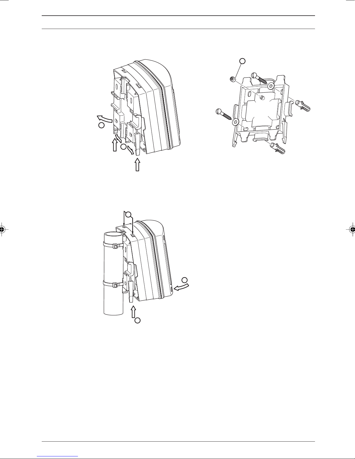
왘 Remove wall/pipe bracket from DMT:
pull the two snap fasteners outwards and push upwards (fig. 1, ➀).
Swing the wall/pipe bracket away from the DMT and pull downwards
(fig. 1, ➁).
왘 Mark two drill holes diagonally opposite one another using the mounting
bracket as a template.
왘 Drill the holes: Ø 8 mm, depth = 50 mm.
왘 Screw the wall/pipe bracket in place inserting the washers (fig. 2).
왘 If the DMT is also to be secured with a screw, pierce the screw hole in the
back of the housing (housing must be open) and attach a rubber insert
(fig. 2, ➀) to the bracket.
왘 Hang the DMT onto the top of the bracket (fig. 3, ➀) and push down
gently against the bracket (fig. 3, ➁), then push upwards until you hear
a click (fig. 3, ➂).
왘 Tighten the locking screw to secure more firmly (housing is open).
Page 10
ProMinent
®
Page 11
Assembly and installation
Fig. 1 Fig. 2
2
1
3515_4
1
3461_4
Fig. 3
1
2
3
3464_4
4.1.2 Pipe mounting
Mounting materials (included in delivery):
1 x wall/pipe bracket
2 x cable ties
1 x sealing cap
1 x locking screw (PT)
Can be mounted onto pipes of diameters from 25 mm to 60 mm.
ProMinent
®
Page 11
Page 12

Assembly and installation
Pipe mounting, please follow the steps below:
왘 Remove wall/pipe bracket from DMT:
pull the two snap fasteners outwards and push upwards (fig. 1, ➀).
Swing the wall/pipe bracket away from the DMT and pull downwards
(fig. 1, ➁).
왘 Fasten the bracket to the pipe using the cable ties or pipe clamps (fig. 3).
왘 If the DMT is also to be secured with a screw, pierce the screw hole in the
back of the housing (housing must be open) and attach a rubber insert
(fig. 2, ➀) to the bracket.
왘 Hang the DMT onto the top of the bracket (fig. 3, ➀) and push down
gently against the bracket (fig. 3, ➁), then push upwards until you hear a
click (fig. 3, ➂).
왘 Tighten the locking screw to secure more firmly (housing is open).
4.1.3 Panel mounting
Fig. 4
IMPORTANT
• The control panel must be thick enough to withstand the
weight of the mounted DMT without buckling. (To achieve
enclosure rating IP 54, steel must be at least 2 mm thick;
plastic should be correspondingly thicker).
NOTE
The DMT will protrude from the control panel approx. 30 mm
once mounted.
Page 12
3463_4
ProMinent
®
Page 13
Assembly and installation
Panel mounting, please follow the steps below:
왘 Decide on the exact position of the DMT on the panel using the drill
template.
왘 Centre punch the holes for the screws and cut-out through the drilling
template.
왘 Drill the four screw holes with a Ø 3.5 mm diameter drill bit.
왘 Punch out the cut-out or drill the four inner holes using an Ø 8 mm
diameter drill bit and pierce out the cut-out with a keyhole saw.
CAUTION
Sharp edges can cause injury.
왘 File off cut edges.
왘 Insert the profile seal into the groove provided on the DMT.
왘 Place the DMT onto the cut-out and screw in place.
IMPORTANT
Check that the seal is located correctly.
IP 54 is only achieved when assembly has been carried out
correctly.
4.2 Installation (electrical)
IMPORTANT
• Installation must be carried out by specially trained
personnel.
• Installation can only be carried out after assembly has been
completed.
• The device must be connected to a protective low voltage
in accordance with EN 60335-1.
• Observe the relevant technical data in chapter 12
throughout installation procedures.
• The current loop must be disconnected from the power
supply during installation.
• The DMT signal cable must not be laid next to leads subject
to high levels of interference. Can lead to malfunction of
DMT.
• The hinge between the front and back sections of the
housing is not particularly strong. When working on the
front section it should be held securely in place.
ProMinent
®
Page 13
Page 14

Assembly and installation
4.2.1 Wall mounting
왘 Unfasten the four housing screws
왘 Lift the front section slightly forwards and then swing open to the left.
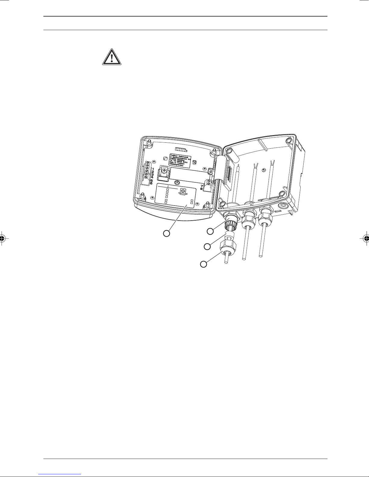
왘 Pierce threaded cable apertures at the bottom of the rear side as required
(fig. 5).
Fig. 5
3468_4
NOTE
• The large gland (M 20 x 1.5) is intended for the sensor
cable.
• Feed the power cable leftwards through the smaller
threaded connector (M 16 x 1.5). Follow with the other
sensor cables (e.g. PT 1000).
왘 Tighten the threaded connectors (fig. 6, ➀) as required.
왘 Use reducers as required (fig. 6, ➁) to adapt the sizes of the threaded
connectors to the actual cable diameters.
왘 Feed the cables into the threaded connectors.
왘 Now proceed according to 4.2.4 Connecting coaxial cable and
4.2.5 Connecting terminals.
Then follow the steps below:
왘 Tighten the locking screws (fig. 6, ➂) for the threaded connectors.
왘 Swing the front section onto the back section.
Page 14
ProMinent
®
Page 15
Cl/ClO /O
-
+
4to20mA
shield
(gr) Pt1000 - /sig.gnd.
(wth) Pt1000 +
(bl) +U
---
(blk)-U
(br) meas.sig.
Pt100x -
Pt100x +
---
liquid pot.
r
ef.el.
glass el.
pH/OR
P
8
6
5
4
3
7
1
Assembly and installation
IMPORTANT
Check that the seal is located correctly. IP 65 is achieved only
when assembly has been carried out correctly.
(If necessary pull the front section forward in order to reduce
the stress on the seal.)
왘 Tighten the housing screws finger tight.
Fig. 6
pH/OR
Cl/ClO /O
P
2
3
liquid pot.
1
(blk)-U
---
Pt100x +
Pt100x -
glass el.
r
ef.el.
2
(bl) +U
3
---
4
(br) meas.sig.
5
(wth) Pt1000 +
6
(gr) Pt1000 - /sig.gnd.
4to20mA
shield
+
7
-
8
4
1
2
3
3465_3
4.2.2 Pipe mounting
See 4.2.1 Wall mounting
4.2.3 Panel mounting
NOTE
The cable must be laid in cable ducting on site to minimise
stresses.
Connect the cable from the back through the cut-out in the control panel:
왘 Follow the steps given in 4.2.4 Connecting coaxial cable and 4.2.5
Connecting terminals.
ProMinent
®
Page 15
Page 16
Assembly and installation
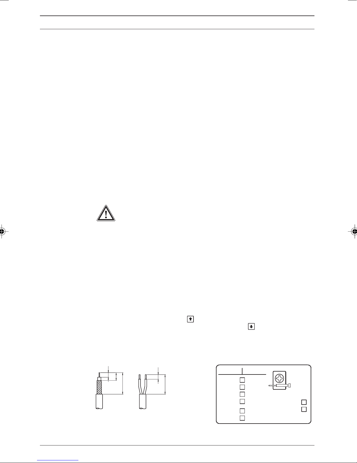
4.2.4 Connecting coaxial cable
The pH resp. redox probe is connected via a coaxial cable:
왘 Strip back to reveal cable shield (reference electrode) in accordance with
fig. 7 (left) and clamp using the shield clip.
The shield clip is connected internally to terminal 3.
Under normal circumstances measuring can be carried out without
connecting a liquid reference potential. In this case provide wire jumpers
between terminals 1 and 2.
When electrical conditions are more complex a potential plug should be
connected to terminal 1. Terminal 2 is left free.
The appendix contains an overview of connection options (terminal
connection plan).
4.2.5 Connecting terminals
왘 Remove insulation from cable ends as shown in fig. 7 (right) and attach
end crimps to each core.
왘 Connect the cables in accordance with the terminal connection plan.
IMPORTANT
• Do not operate PROFIBUS® variants at voltages over 30 V.
•
Connect PROFIBUS® variant power supplies via terminals 3
and 4 on the PROFIBUS® circuit board in the back section,
not terminals 7 and 8 in the front section.
NOTE
• The terminal connection plan is given in the appendix.
There is also a panel giving connection information affixed
to the housing near the terminals (fig. 6, and fig. 8).
• Push the cable through the housing until the front section
can be moved up and down easily.
• If the LC display is too weak, reduce the brightness using
the up arrow key
. If the display is too dark, increase the
brightness using the down arrow key .
Fig. 7 Fig. 8
7
12
33
7
3459_4
pH/ORP
liquid pot.
30
glass el.
Pt100 +
Pt100 -
---
ref.el.
Cl/ClO /O
3
2
(blk)-U
1
(bl) +U
2
---
3
4
(br) meas.sig.
(wth) Pt1000 +
5
(gr) Pt1000 - /sig.gnd.
6
shield
4to20mA
+
7
8
-
Page 16
ProMinent
®
Page 17

Device overview and control elements
5 Device overview and control elements
Fig. 9
Measured
variable label
LC-Display
Change key
Back key
Down key
CAL key
Enter Key
Up key
3456_4
ProMinent
®
Page 17
Page 18

Function description
6 Function description
6.1 General
The DULCOMETER® MEASUREMENT TRANSDUCER (DMT) is a microprocessor controlled on site measurement transducer. It displays the
selected measured variable and produces a proportional output signal. It can
also use temperature as a correction variable. The user can specify these
functions using the operating menu.
The user can switch between the measured variables pH value, redox
potential and temperature.
The inputs are collectively electrically insulated against the output.
In the event of a fault the DMT indicates an error message on the LC display
and produces an increased current (23 mA) through the ring circuit.
The DMT is also available for the following measured variables:
• Conductivity
• Chlorine
Measured
variable
temperature
Block circuit diagram
A
D
µP
Keypad LC display
EEPROM
(parameter memory)
FlashROM
(program memory)
D
A
Power supply,
current control
Signal
output
4 ... 20 mA
at
16 ... 40 V DC
and/or
30 V DC
(PROFIBUS
variant)
®
Page 18
ProMinent
®
Page 19

Function description
6.2 Key functions
The key are used to alter the DMT settings and have the following
functions:
In the permanent display / In the menu options
in the info display
Change key Toggles between permanent Scrolls through values of the
display and info display current menu option
modes
Back key Exits info display mode and Exits to info display without
returns to permanent display saving changes to values
mode
Enter key Accesses menu option Saves changes to values in
(from an info display) current menu option and
accesses the next info
display or another menu
option
CAL key Opens the calibration menu Activates calibration in
(from permanent display) calibration menu (pH only)
Down key Alters brightness of the Changes a value
LC display
Up key (in permanent display mode)
6.3 Operating menu, schematic
The operating menu comprises:
• the permanent display
• the calibration menu
• the info displays (info level)
for the display of pre-set parameters resp. general settings
• menu options (settings level)
for altering parameters resp. general settings
ProMinent
®
Page 19
Page 20

Function description
pH only
Permanent
display
Info display 1
Info display X
Info level Settings level
Calibration menu
Menu option 1
Menu option 1
Menu option 2
= Request access code
(only when activated by user)
6.4 Negotiating operating menu
NOTE
• The back key
any time. Depending upon where you are in the operating
menu, you will return either to the permanent display or to
the corresponding info level.
• The display will automatically return to permanent display
if you do not press a key within 5 min. (does not save
changes to values).
• If an access code has been activated by the user, access
code protection is applied to both the calibration menu and
the settings level menu options.
To access these menu options the access code must be
entered when it is requested and confirmed with the enter
key . Access restriction is reinstated each time you
return to the permanent display.
• The access code is factory set to 5000 (inactive).
can be used to exit the operating menu at
Page 20
ProMinent
®
Page 21

Function description
6.4.1 Calibration menu (pH only)
Access the calibration menu from the permanent menu using the CAL key
(further details given in 8.2 Calibrating the pH meter)
6.4.2 Info display
Access the first info display of the info level from the permanent display using
the change key .
Use the change key
the permanent display after the last info display.
6.4.3 Menu options
Use the enter key to access the menu options associated with that info
level.
6.4.4 Negotiating the menu options
input: sensor
unit: ˚C
offset = 0.00 ˚C
meas. val. = 21.00 ˚C
to access the other info displays in turn. Returns to
= adjustable numerical
values/texts flashing
Press the change key to activate all adjustable values in a menu option.
Flashing values can be altered. Use the arrow keys / to alter numerical
values or texts.
Keystrokes perform the following actions:
•1 x short keystroke reduces/increases a numerical value by one
increment or alters a text
• Holding the key down for longer alters numerical values increasingly
rapidly.
Use the enter key
to save changed values in the menu option. You will
then automatically enter the next info display or (if available) the next menu
option.
NOTE
Your entries become active immediately and are stored
permanently when you press the enter key .
If you do not wish to save changes, exit the menu option using the back
key
. You will then return to the info display for that menu.
ProMinent
®
Page 21
Page 22

DMT settings
Permanent display Calibration of pH probe Zero point and slope
7 DMT settings
NOTE
• Settings need only be changed if your process
requirements differ from factory general settings.
• If your DMT does not display the required settings option,
check the general settings of your device as described in
chapter 7.1.7.
Menu overview table
pH probe parameters Zero point, slope and probe
resistance
Redox probe test Compare with buffer Probe resistance
Parameter Detection means:
Temperature • sensor
measurement • manual (enter value)
Unit of measurement
• °C
• °F
Parameter Value:
Output current •
General settings Measured variable: Settings configuration Access
proportional measured variable:
measured variable at 4 mA
measured variable at 20 mA
• manual (enter value)
• pH code
• ORP (redox)
• temperature
= Request access code
(if activated by the user)
Page 22
ProMinent
®
Page 23

7.1 Measured variables pH and redox
7.1.1 Menu overview: measured variable pH
NOTE
The following menu is only an example.
The displays can vary depending upon the general settings.
DMT settings
pH
pH
7.12
12.5 mA 21.0 ˚C
param. measurement
zero point. = -0.1 mV
slope = 60.30 mV/pH
probe check: on
param. temperature
input: sensor
unit: ˚C
param. output signal
output: meas. value
4 mA: 2.00 pH
20 mA: 12.00 pH
general settings
DMTaW090P10E0220
2.1.06
zero point = -0.1 mV
slope = 60.30 mV/pH
probe check: on
meas. val. = 7.12 pH
input: sensor
unit: ˚C
offset = 0.00 ˚C
meas. val. = 21.00 ˚C
output: meas. value
4 mA: 2.00 pH
20 mA: 12.00 pH
device type
!! correct probe ??
type = pH
DMTaW090P10E0220
= Request access code
(if activated by the user)
general settings
language
DMTaW090P10E0220
E = english
ProMinent
®
general settings
change
access code = 5000
free access
Page 23
Page 24

DMT settings
7.1.2 Menu overview: measured variable redox
NOTE
The following menu is only an example.
The displays can vary depending upon the general settings.
Redox
mV
312
12.5 mA 21.0 ˚C
checking ORP-probe
param. temperature
input: sensor
unit: ˚C
param. output signal
output: meas. value
4 mA: 0 mV
20 mA: 1000 mV
general settings
DMTaW090R10E00220
2.1.06
probe in buffer!
faulty probe!!
buffer value: 465 mV
meas. value: 509 mV
unit: °C
offset = 0.00 °C
meas. val. = 21.00 °C
output: meas. value
4 mA: 0 mV
20 mA: 1000 mV
device type
!! correct probe ??
type = ORP (Redox)
DMTaW090R10E0220
= Request access code
(if activated by the user)
check dry probe
resistance = 1.23 MΩ
allowed > 2 MΩ
faulty probe !!
general settings
language
DMTaW090R10E0220
E= english
Page 24
general settings
change
access code = 5000
free access
ProMinent
®
Page 25

7.1.3 Parameter settings (pH only)
DMT settings
pH
param. measurement
zero point = -0.1 mV
slope = 60.30 mV/pH
probe check: on
zero point = -0.1 mV
slope = 60.30 mV/pH
probe check: on
meas. val. = 7.12 pH
or
zero point = -0.1 mV
slope = 60.30 mV/pH
probe check: on
resistance = 1.23 MΩ
The following settings options are available to you:
Zero point
and slope 왘 Enter the calibration values of the pH probe under “zero point” and
“slope” if these have been obtained by other means than via the DMT
calibration menu.
The current pH value is displayed under “meas. value” for monitoring
purposes.
Probe check 왘 Select on or off under “probe check” to activate/deactivate the pH
probe check.
If the probe check is active (on flashes) the resistance value of the pH
probe is displayed under “resistance”.
If the resistance value falls below 2 MΩ at any time during operation for
longer than 1 minute the error message “defective pH probe !!” appears in
the permanent display. Alternatively, if it is above 200 MΩ and the
measurement signal is fluctuating significantly, the error message “pH input
error!” is activated along with the display value “-2.00 pH” or “16.00 pH”.
7.1.4 Checking the ORP probe (redox only)
Redox
ProMinent
®
checking ORP-probe
NOTE
Sample liquid temperatures below 20 °C or above 60 °C can
cause incorrect signals during probe monitoring. In this case
we recommend that you switch off the probe check as long as
the pH probe is functioning correctly.
probe in buffer!
faulty probe!!
buffer value: 465 mV
meas. value: 509 mV
check dry probe
resistance = 1.23 MΩ
allowed > 2 MΩ
faulty probe !!
NOTE
The output current value is frozen during probe testing at,
depending upon the general settings, the last measured value
(HOLD) or at 23 mA (see chapter 7.1.7 General settings).
Page 25
Page 26

DMT settings
Two different test options are available:
Comparison
with buffer You can check the probe in the first menu option by measuring the redox
potential of a buffer solution:
The suggested “buffer value” (the redox potential for the buffer solution) is
220 mV or 465 mV. This value can be changed. The device compares the
buffer value with the measured variable and displays an error message
“faulty probe !!” if the difference is greater than 40 mV.
Probe
resistance The probe can be checked in the second menu option by measuring the
electrical resistance between the electrodes of the probe (must be dry):
It is particularly important that there is no residual moisture adhering to the
probe.
If the resistance measured is less than 2 MΩ the device will display the error
message “faulty probe !!”.
7.1.5 Parameters: Temperature
NOTE
• The DMT automatically detects whether a PT 1000 or
PT 100 is connected.
• If there is no temperature gauge connected the
temperature measurement should be set to “none”
or “manual” (see chapter 7.1.7 General settings).
Depending upon the “temp. meas.” general setting you have the following
options:
7.1.5.1 General setting: Temperature measurement = automatic
왘 Select the unit of measurement for temperature °C or °F under “unit”.
왘 Enter the difference ∆t under “offset” to a reference temperature
measurement (see chapter 7.5.5 Calibrating the Pt 100 temperature
gauge).
The actual temperature measured is displayed under “meas. val.”.
Page 26
ProMinent
®
Page 27

DMT settings
7.1.5.2 General setting: Temperature measurement = manual
(pH only)
pH
pH
param. temperature
input: manual
unit: ˚C
T = 22.6 ˚C
unit: ˚C
왘 Enter the process temperature under “T”.
왘 Select the temperature unit °C or °F under “unit”.
7.1.5.3 General setting: Temperature measurement = automatic or
manual (pH only)
param. temperature
input: manual
unit: ˚C
input: sensor
unit: ˚C
offset = 0.00 ˚C
meas. val. = 21.00 ˚C
or
input: manual
T = 22.6 ˚C
Unit: ˚C
왘 Under “input” select sensor or manual:
Select sensor if a temperature gauge is connected (temperature
measurement = automatic):
Select manual if the user is going to enter the process temperature
(temperature measurement = manual).
The selection made under “input” affects subsequent settings options.
Sensor If you have selected sensor in the “input” option:
왘 Select the unit of measurement for temperature °C or °F under “unit”.
왘 Enter the difference ∆t under “offset” to a reference temperature
measurement (see 7.1.5.5 Calibrating the Pt 100 temperature gauge).
The actual temperature measured is displayed under “meas. val.”.
Manual If you have selected manual in the “input” option:
왘 Enter the process temperature under “T”.
왘 Select the temperature unit °C or °F under “unit”.
7.1.5.4 General setting: Temperature measurement = none
No info display appears in the operating menu.
No temperature measurement is carried out.
ProMinent
®
Page 27
Page 28

DMT settings
7.1.5.5 Calibrating the PT 100 temperature gauge
NOTE
You need only calibrate the temperature gauge if
-You have a PT 100 temperature gauge and the sensor cable
is longer than 4 m.
-You have a precision measurement device (the DMT
measures to ±0.5 °C / ±0.9 °F accuracy).
• Do not replace the temperature sensor during calibration!
왘 Immerse the DMT temperature gauge and the reference measurement
device into the same liquid sample.
왘 Read off the value from the reference measurement device once the
temperature is stable.
왘 Set the correction value under “offset” until the temperature value is
identical to the reference value.
7.1.6 Parameter output
Depending upon the “output” general setting you have the following settings
options:
7.1.6.1 General setting: output current = measured value
(= 0 in identity code)
왘 Under “4 mA” enter the value at which the output current should be
4 mA.
왘 Under “20 mA” enter the value at which the output current should be
20 mA.
During calibration or checking of the ORP probe, the output current increases
to 23 mA.
Page 28
ProMinent
®
Page 29

DMT settings
7.1.6.2 General setting: output current = adjustable
(= 1 in identity code)
This setting serves as a function check.
왘 Enter under “l” any output current between 4 and 20 mA.
The current pH value or the current ORP are displayed in “meas. val.”
for verification purposes.
7.1.6.3 General setting: output current = measured value or adjustable
(= 2 in identity code)
pH
Redox
param. output signal
output: meas. value
4 mA: 2.00 pH
20 mA: 12.00 pH
param. output signal
output: meas. value
4 mA: 0 mV
20 mA: 1000 mV
output: meas. value
4 mA: 2.00 pH
20 mA: 12.00 pH
or
output: constant
I = 10.2 mA
meas. value = 7.11 pH
output: meas. value
4 mA: 0 mV
20 mA: 1000 mV
or
output: constant
I = 10.2 mA
meas. val. = 502 mV
왘 Under “output” select meas. value or constant:
Select meas. value if you require the output current to be proportional to
the measured value (output = meas. val.);
Select constant if you are going to enter the output current manually
(output = manual).
The “output” selection affects subsequent settings options:
Measured
variable If you have selected meas. value under “output”:
왘 Under “4 mA” enter the value at which the output current should be
4 mA.
왘 Under “20 mA” enter the value at which the Output current should be
20 mA.
ProMinent
®
Page 29
Page 30

DMT settings
Constant If you have selected constant under “output”
왘 Enter under “l” any output current between 4 and 20 mA.
The current pH/redox value is displayed under “meas. value” for
monitoring purposes.
This setting serves as a function check. During calibration or checking of the
ORP probe, the output current increases to 23 mA.
7.1.6.4 General setting: output current = measured value + adjustable +
HOLD
(= 3 in identity code)
In this general setting, the DMT can be adjusted as shown in 7.1.6.1 or
7.1.6.3. The following differences should be noted:
pH
For DMT pH, the output current remains at the output current value last
reported (HOLD function) during calibration. The output current freezes the
moment the menu option “input” is exited using the CAL key. This output
current corresponds to the last measured pH value. The HOLD value of the
output current is held until the calibration is completed. It is also possible to
set a certain HOLD value in the first measuring point of the calibration menu
(see 8.2.2).
Redox
With regard to DMT redox, the output current increases during calibration of
the ORP probe to the output current value last displayed (HOLD function)
upon activation of the ENTER key. This output current corresponds to the last
measured redox value. The HOLD value of the output current is held until the
menu “checking of redox probe” is exited.
7.1.6.5 General setting: output = 4 mA
(= 4 in identity code)
No info display appears in the operating menu.
The DMT emits a constant output current of 4 mA.
This setting serves as a function check and is selected if the DMT is to be
used purely as a display device (current consumption is minimal in this case!).
Page 30
ProMinent
®
Page 31

7.1.7 General settings
DMT settings
pH Redox
general settings
DMTaW090P10E0220
2.1.06
device type
!! correct probe ??
type = pH
DMTaW090P10E0220
general settings
change
access code = 5000
free access
general settings
language
DMTaW090P10E0220
E= english
7.1.7.1 Changing the device type
You can select the measured variables, pH or redox potential, in the first
menu option “device type”.
왘 Under “type” select pH or ORP (redox).
Depending upon your choice the corresponding identity code position alters:
pH = “P”, redox = “R”.
If you have confirmed the change of measured variable with the enter key
the output current will change immediately.
The settings for each measured variable are unaffected even after a different
selection has been made and are reinstated if the selection is reversed.
7.1.7.2 Changing general settings
You can adapt the DMT to your individual process requirements in the
second menu option “general settings”.
Access the individual identity code positions using the change key
.
Non-alterable features are automatically bypassed.
The following tables show the settings options depending upon the selected
measured value (the sequence from left to right corresponds to the identity
code position).
Measured variable pH
Language Automatic buffer Temperature Output Other
detection measurement settings
D = German 0 =ProMinent 0 = automatic 0 = measured variable; 0 =standard
E = English buffer set 1 = manual fault 23 mA,
F = French D = DIN 19266 2 = automatic or at calibration 23 mA
P = Polish buffer set manual 1 = manually adjustable
I = Italian V = automatic 9 = none current value
S = Spanish adjustment 2 = measured variable
or manual:
at fault 23 mA,
at calibration 23 mA
3 = measured variable
or manual:
at fault 23 mA,
when calibrating the last
measured value (HOLD)
4 = constant 4 mA
current
ProMinent
®
Page 31
Page 32

DMT settings
Measured variable redox
Language Probe type Temperature Output Other
measurement settings
D = German 0 =standard 0 = automatic 0 = measured variable: 0 =standard
E = English 9 = none at fault 23 mA,
F =French at calibration 23 mA
P = Polish 1 = manually adjustable
I = Italian current value
S = Spanish 2 = measured variable
or manual:
at fault 23 mA,
at calibration 23 mA
3 = measured variable
or manual:
at fault 23 mA,
when calibrating the last
measured value (HOLD)
4 = constant 4 mA
current
7.1.7.3 Changing access code
The factory pre-set access code is 5000. This setting allows unlimited access
to the calibration menu and the menu options in the settings level.
This code can be changed in the third menu option “change access code”.
Use the change key
to move to individual digits.
The new code is confirmed and activated with the enter key .
NOTE
• If an access code has been activated, both the calibration
menu and the menu options are access-protected.
To gain access, enter the access code when requested
to do so and confirm using the enter key
. Access
protection is reactivated when the DMT returns to
continuous display mode.
• Deactivate the access code by resetting the code to 5000
in the “change access code” menu option.
Page 32
ProMinent
®
Page 33

DMT settings
7.2 Measured variable temperature
7.2.1 Menu overview measured variable, temperature
NOTE
The following menu is only an example.
The displays can vary depending upon the general settings.
T
21.0
7.4 mA
param. temperature
unit: ˚C
param. output
output: meas. value
4 mA: 0.0 ˚C
20 mA: 100 ˚C
general settings
DMTaW090T10E0020
2.1.06
˚C
unit: ˚C
offset = 0.00 ˚C
meas. val. = 21.00 ˚C
output: meas. value
4 mA: 0.0 ˚C
20 mA: 100 ˚C
device type
!! correct probe ??
type = temp.
DMTaW090T00E0020
general settings
change
access code: 5000
free access
= Request access code
(only when activated by user)
general settings
language
DMTaW090T00E0020
E= english
ProMinent
®
Page 33
Page 34

DMT settings
7.2.2 Parameters temperature
왘 Select the temperature unit ˚C or ˚F under “unit”.
왘 Enter under “offset” the difference ∆t from a reference temperature
measurement (see 7.1.5.5 Calibrating the Pt 100 temperature gauge).
The actual measured temperature is displayed under “meas. val.”.
NOTE
• The DMT automatically recognises whether a PT 1000 or a
PT 100 has been connected.
7.2.3 Parameter output
You have the following settings options, depending on the “output” type you
selected under general settings:
7.2.3.1 General setting: output current = measured variable
(= 0 in the identity code)
왘
Under “4 mA”, enter the value at which the output current should be 4 mA.
왘 Under “20 mA”, enter the value at which the output current should be
20 mA.
7.2.3.2 General setting: output current = adjustable
(= 1 in the identity code)
왘 Under “l”, enter an output current between 4 and 20 mA.
This setting is used for the function check.
Page 34
ProMinent
®
Page 35

DMT settings
7.2.3.3 General setting: output current = measured value or adjustable
(= 2 in the identity code)
왘 Under “output”, select meas. value or constant:
Select meas. value if the output current should be proportional to the
measured value (output = measured value):
Select constant if the output current is to be entered manually
(output = adjustable).
The selection you make under “output” influences the subsequent settings
options:
If you selected “output” meas. value:
Under “4 mA”, enter the value at which the output current should be 4 mA.
왘
왘 Under “20 mA”, enter the value at which the output current should be
20 mA.
Entry If you selected “output” constant:
왘 Under “l”, enter any output current between 4 and 20 mA.
7.2.3.4 General setting: output = 4 mA
(= 4 in the identity code)
No information display will appear in the operating menu.
The DMT emits a constant output current of 4 mA.
This setting is used for the function check and/or is selected if the DMT is to
be used purely as a display device (the power consumption is minimal in this
case).
ProMinent
®
Page 35
Page 36

DMT settings
7.2.4 General settings
T
general settings
DMTaW090T10E0020
2.1.06
device type
!! correct probe ??
type = temp.
DMTaW090T10E0020
general settings
change
access code = 5000
free access
general settings
language
DMTaW090T10E0020
E = english
7.2.4.1 Changing device type
The first menu option, “device type”, is used to switch between the measured
variables pH value, redox voltage or temperature:
왘 Under “type”, select pH, ORP (redox) or Temperature.
The corresponding identity code position changes depending on your choice:
pH= “P”, redox = “R”, temperature = “T”.
If you confirm the change of measured variable using the enter key
,
the output current changes immediately.
The settings for each measured variable are unaffected by switching from one
to another, i.e. you do not need to re-set them when re-selecting a measured
variable.
7.2.4.2 Changing general settings
The second menu option; “general settings”, is used to adapt the DMT to
your specific process requirements.
Scroll through individual identity code positions using the “Change” key
until you reach the one you require. Non-adjustable features are automatically
bypassed.
The following tables show the settings options for each measured variable
(the sequence from left to right corresponds to the identity code positions).
Measured variable temperature
Language Probe type Temperature Output current Additional
input settings
D = German standard 0 = sensor 0 = measured variable; 0 =standard
E = English 0 =PT 100 or PT 1000 (100) at fault 23 mA
F = French PT 1000 at calibration 23 mA
P = Polish 1 = adjustable output
I = Italian 2 = measured variable
S = Spanish or adjustable;
at fault 23 mA
at calibration 23 mA
4 =4 mA constant current
Page 36
ProMinent
®
Page 37

DMT settings
7.2.4.3 Change access code
The factory-set default access code is 5000. This setting allows unlimited
access to the calibration menu and the settings level menu options.
This code can be changed in the third menu option; “change access code”.
Use the change key
enter key. Once all digits have been selected you can activate the code by
pressing the enter key once more.
NOTE
• If an access code has been activated, both the calibration
menu and the menu options are access-protected.
To gain access, enter the access code when requested to
do so and confirm using the enter key
protection is reactivated when the DMT returns to
continuous display mode.
• Deactivate the access code by resetting the code to 5000 in
the “change access code” menu option.
to bring up the individual digits and confirm using the
. Access
ProMinent
®
Page 37
Page 38

mV/pH
m
V
-60 +60+500-50
300
s
40 656345
The pre-set time depends upon the
temperature and the cable length.
Depending on the system the setting
time can be more than 60 seconds.
Pre-set time:
Slope:
Admissible range
Zero point:
visible = probe OK
not visible = on the limit of admissible range
and/or not in order
Condition:
Zero point
Slope
Pre-set time
Display:
59,16
Operating the DMT
8 Operating the DMT
8.1 Permanent display
pH
Redox
pH
Information about the probe condition
7.12
12.5 mA 21.0 ˚C
mV
312
12.5 mA 21.0 ˚C
The permanent display allows you to monitor the DMT measured values
during operation.
The permanent display can indicate the following (depending upon
general settings):
• Measured variable • Information about the probe condition
• Correction variable • Error messages
• Output current
8.1.1 Probe condition information (pH only)
Page 38
Optimum range
Admissible range
Optimum range
ProMinent
®
Page 39

Operating the DMT
8.1.2 Brightness of LC display
You can alter the brightness of the LC display in the permanent display:
왘 Increase brightness using the down arrow key
arrow key .
8.2 Calibrating the pH meter
The pH probe condition is a key factor in the quality of the measurement. The
pH probe must therefore be re-calibrated at regular intervals with the aid of
buffer solutions. The DMT incorporates automatic buffer detection.
8.2.1 Automatic buffer detection
The tables for the following two buffer solution sets are contained in the
program memory.
Temp. ProMinent buffer table DIN 19266 buffer table
°CpH pH
0 4.05 7.13 10.26
5 4.04 7.07 10.17 4.00 6.95 10.25
10 4.02 7.05 10.11 4.00 6.92 10.18
15 4.01 7.02 10.05 4.00 6.90 10.12
20 4.00 7.00 10.00 4.00 6.88 10.07
25 4.00 6.98 9.94 4.01 6.86 10.01
30 4.00 6.98 9.90 4.01 6.85 9.97
40 4.00 6.97 9.82 4.04 6.84 9.89
50 4.00 6.96 9.75 4.06 6.83 9.83
60 4.00 6.97 9.68 4.09 6.84
70 4.01 6.98 9.62 4.13 6.85
80 4.02 6.99 9.55 4.16 6.86
or reduce using the up
We recommend that you use the buffer solutions obtainable from ProMinent
for calibration purposes.
Select a buffer set which is higher than the general setting (see chapter 7.1.7)
If V = automatic adjustment has been selected the corrected values are
saved and used for buffer detection during the subsequent calibration
process.
On delivery the program memory contains the ProMinent buffer table as the
V-table.
ProMinent
®
Page 39
Page 40

Operating the DMT
8.2.2 The calibration process
Calibration menu overview
8.2.2.1 2 point calibration
NOTE
• The back key can be used to exit the calibration menu at
any time. You will then return to the permanent display.
• The output current is frozen for the duration of the calibration at, depending upon general settings, the last
measured value (HOLD) or at 23 mA (see chapter 7.1.7
General settings).
• Inadmissible values render the ongoing calibration invalid.
The previous calibration values are retained. The error
messages are explained in chapter 9.2.
• Please dispose of spent buffer solution.
Page 40
ProMinent
®
Page 41

8.2.2.2 1 point calibration
Operating the DMT
Proceed as follows to call up the calibration menu:
pH
7.12
12.5 mA 21.0 ˚C
pH
input: sensor
buffer temp. = 20.3 ˚C
HOLD 7.12 pH
HOLD 12.12 mA
input: manual
buffer temp. = 20.3 ˚C
or
HOLD 7.12 pH
HOLD 12.12 mA
Starting
calibration 왘 Press the CAL key when in the permanent display mode while the pH
probe is immersed in the liquid sample.
왘 Under “input” set the detection method of the buffer temperature
(correction value):
Sensor (if the pH sensor incorporates a temperature gauge) or
manual (if using a separate temperature gauge).
If you select manual, you must set the buffer temperatures under “buffer
temp.” using the up and down arrow
/ keys.
This setting is only valid during calibration.
왘 You can change the pH HOLD value under “HOLD”. This setting is only
valid during calibration.
왘 Remove the pH probe from the liquid sample, rinse and immerse in the
first buffer solution.
왘 Press the CAL key to start automatic buffer detection:
ProMinent
®
Page 41
Page 42

Operating the DMT
pH
pH cal1
4.02 4.01 4.04
recogn.
T = 20.3 ˚C
The progress of the buffer detection is indicated by a time bar. The calculation of the calibration parameters begins automatically after the buffer
detection. This is also indicated by a time bar.
If you have selected sensor as the detection method for the buffer temperature, the current measured buffer temperature is displayed under “T”. If you
have selected manual, the manually entered buffer temperature is displayed
under “T”.
The buffer value can be corrected during calibration using the / arrow
keys. If the sensor signal is unstable the time bar will wait until it becomes
stable.
왘 After completion of this calibration stage the display shows the next
menu option for 1 point calibration:
The buffer value can be corrected once again at this point using the arrow
keys / .
pH cal1
calibr.
T = 20.3 ˚C
pH cal1
end = or cal2 = CAL
T = 20.3 ˚C
Progress from this point onwards depends upon whether you have selected a
1 point calibration or a 2 point calibration (recommended!).
1 point
calibration 왘 Press the enter key
to end 1 point calibration.
The zero point is calibrated if the buffer value is between 5.5 pH and 8.0 pH.
The slope is calibrated if the buffer value is less than 5.5 pH or greater than
8.0 pH.
왘 Proceed as for “conclude calibration”.
2 point
calibration 왘 For a 2 point calibration remove the pH probe from the first buffer
solution, rinse and immerse in the second buffer solution.
왘 Press the CAL key
to restart automatic buffer detection.
Buffer detection and calibration take place as described above.
Page 42
ProMinent
®
Page 43

Operating the DMT
왘 After completion of this calibration stage the display shows the next
menu option for 2 point calibration:
The buffer value can be corrected once again at this point using the arrow
keys
왘 Press the enter key to end 2 point calibration.
왘 Proceed as for “conclude calibration”.
Conclude
calibration The calibration values (zero point and slope) are now displayed:
pH
zero point = -0.12 mV
slope = 58.32 mV/pH
acceptance
meas. val. = 7.21 pH
The current pH value is shown under “meas. val.”.
왘 Press the enter key
without saving the values.
/ .
to adopt the values or the back key to exit
The display changes to permanent display. The calibration is complete.
NOTE
Inadmissible values render the current calibration process
invalid.
The previous calibration values are retained.
The error messages during calibration are explained in
chapter 9.2.
ProMinent
®
Page 43
Page 44

Troubleshooting
9Troubleshooting
9.1 Error messages during operation
The following error messages can appear in the permanent display during
operation:
Message Displayed Cause of fault Remedy
value
Output overflow Measured Warning: detected current value Change configuration if
value greater than pre-set necessary
20 mA value
Output underflow Measured Warning: detected current value Change configuration if
value less than pre-set necessary
4 mA value
pH input error ! -2.00 pH Probe not present or lead Check probe connection
or damaged (switch off probe check if
16.00 pH necessary)
pH input error ! ~7.00 pH Short circuit Check probe connection
(probe resistance ≅ 0 Ω)
defective pH probe !! Measured Measured probe Replace probe (switch off
value resistance < 2 MΩ probe check if necessary)
ORP input error ! Measured value > 1200 mV or Check probe connection
< -1200 mV,
resp. fluctuating significantly
temp. input error ! 999.9 ° Probe not present or Check probe connection
lead damaged (set temperature measurement
to manual if necessary)
temp. input error ! -99.9 ° Short circuit Check probe connection
(set temperature measurement
to manual if necessary)
The error message disappears automatically once you have remedied the
fault.
Page 44
ProMinent
®
Page 45

Troubleshooting
9.2 Error messages while calibrating the pH meter
The following error messages can appear in the corresponding menu options
during calibration:
Error message Cause Effect
Zero point <-60mV !!! N < -60 mV Previous zero point and slope retained
Calibration failed Replace probe
Zero point > 60mV !!! N > +60 mV ”
Calibration failed
Slope < 40mV/pH ! S < 40 mV/pH ”
Calibration failed (S < 67 %)
Slope > 65mV/pH ! S > 65 mV/pH ”
Calibration failed (S > 111 %)
Warning Cause Effect
Measured value t
unstable !!!
Buffer differential < 2 pH ! ∆
False buffer value - Set correct buffer value
* The admissible setting time is: t
> 30 s *
cal
< pH 2 Use second buffer solution
Buffer
< 30 s for a value fluctuation ∆U < 2 mV/s
cal
IMPORTANT
The sensor monitoring is deactivated during the calibration
process!
ProMinent
®
Page 45
Page 46

Maintenance and repair / Disposal
10 Maintenance and repair
Maintenance The DMT requires no maintenance.
You should clean the housing with a damp, soapy cloth and then rub dry.
IMPORTANT
Solvents may attack the surfaces and must not be used.
Repair Please return the DMT to ProMinent Dosiertechnik GmbH for repair.
11 Disposal
IMPORTANT
Electronic waste is treated as special waste!
Observe current nationally and locally applicable directives.
Page 46
ProMinent
®
Page 47

12 Technical data
Electrical data
Device Protection class: III
Supply voltage: - 4-20 mA (two wire) current loop,
24 V DC (16...40 V DC), protective low voltage
- PROFIBUS®-DP, 24 V DC (16...30 V DC),
protective low voltage
The supply voltage level must not fall below
16 V at any time
Signal output: 4 … 20 mA in normal operation,
23 mA to signal fault,
Ohmic resistance 50 Ω
Enclosure
ratings When installed correctly the following enclosure ratings apply:
Wall/pipe mounted: IP 65 in accordance with DIN VDE 0470-1
Control panel mounted: IP 54 in accordance with DIN VDE 0470-1
Measured
variable, pH Measurement range: -1 … +15 pH at 0 … 100 °C
Reproducibility: 0.01 pH
Operating measurement
deviation: max. 0.02 pH at 25 °C ambient temperature
Insulation voltage: 500 VDC; electrically insulated against
ring circuit
Input resistance: Glass electrode: > 1012 Ω
Reference electrode: All reference electrodes can be connected
to diaphragm
Resolution: 0.01 pH
Measured
variable, redox Measurement range: -1200 … +1200 mV
Reproducibility: 1 mV
Operating measurement
deviation: max. 2 mV at 25 °C ambient temperature
Insulation voltage: 500 VDC: electrically insulated against
ring circuit
Input resistance: > 1012 Ω
Reference electrode: All reference electrodes can be connected
to diaphragm
Measured
variable/ Resolution: 1 mV
Correction
variable,
temperature Measurement range: -20 °C … 150 °C
Measurement deviation: max. 0.3 °C (PT 1000 at 25 °C ambient
temperature)
max. 0.5 °C (PT 100 at 25 °C ambient
temperature)
Resolution: 0.1 °C
Display Principle: LCD (liquid crystal display)
Technical data
ProMinent
®
Page 47
Page 48

Technical data / Spare parts and accessories
Ambient conditions
Operating temperature: 0 … 55 °C
Storage temperature: -20 … 70 °C
Air humidity: max. 95 % rel. humidity, non condensing
Control
panel
Dimensions and weight
Dimensions: Wall/pipe mounted version 126x136x78 mm
(WxHxD)
Panel mounted version 35 mm, 30 mm (D
Weight: Wall mounted, 450 g
D
o
, Do)*
i
Panel mounted, 300 g
*D
= depth inside, Do = depth outside
i
Admissible cable diameters: threaded connector:
M 20 x 1.5: Terminal area Ø 2 … Ø 7 mm
(SW 22)
M 16 x 1.5: Terminal area Ø 5 … Ø 10 mm
(SW 19)
reducers:
M 20: Terminal area Ø 4 … Ø 13 mm
M 16: Terminal area Ø 3 … Ø 9 mm
D
i
Admissible lead
cross sections: 0.14 … 0.75 mm
Admissible screen diameters:
Ø 2 … Ø 5 mm
2
Material information
Housing: PPE-GF10
Wall/pipe bracket: PPE-GF20
Keypad: Silicon
Housing seal: Silicon
13 Spare parts and accessories
Assembly kit for wall/pipe mounting Order no. 1003205
Pipe clamps for pipe mounting Order no. 1002777
Plug-in power supply 90-264 V AC/24 V DC Order no. 1006100
Probes See product catalogue
Probe cable See product catalogue
Page 48
NOTE
Please give the identity code when ordering electronic
component kits.
ProMinent
®
Page 49

Conformity declaration
ProMinent
®
Page 49
Page 50

Terminal connection plan pH/redox/temperature
Inputs, Output
connection variations
Internal
External
pH/redox ORP
combination probe
without liquid
reference potential
5566
44332211
-
+
pH/redox ORP
combination probe
with liquid
reference potential
--
+
XY
Signal
Shield
ϑ
Pt 1000/
Pt 100
pH/redox pH/redox
ϑ
Pt 1000/
Pt 100
Signal
Shield
Potential plug
pH/redox ORP
separate probe system
564321
+
Z
Signal
Shield
ϑ
Pt 1000/
Pt 100
pH/redox
Ref. electrode
(not PROFIBUS
variants)
87
-
+
Current loop
4-20 mA/
Supply voltage
16-40 V DC
®
3
Shield to shield clip
421 21
Shield to shield clip
Internal
External
Detail ZDetail YDetail X
3344
21
Wire jumperWire jumper
Shield to shield clip
Connection variant temperature
Resistance thermometer
564321
-
+
(not PROFIBUS
Output
variants)
87
+
®
-
Page 50
ϑ
Pt 1000/
Pt 100
Current loop
4-20 mA
Supply voltage
16-40 V DC
ProMinent
®
Page 51

Wiring example - two wire system
1
=
2
3
4
+
-
+
-
+
-
5
=
-
+
6
-
+
~
1 DMT transducer
2 Controller
3 Meter
4 Recorder
5 24 V DC (16...30 V DC/40 V DC) power supply unit
6 4-20 mA current loop
IMPORTANT
• The signal inputs of all devices in the current loop must be
electrically isolated from the current output.
• Take into account the sum of the ohmic resistances of all
devices in the current loop (excluding power supply).
The input voltage of the transducer must never drop below
16 V during operation.
The measured value will otherwise be wrong.
ProMinent
®
Page 51
Page 52

+ - + -
Intern Extern
1 2 3 4
+ - + -
PROFIBUS® circuit board terminal connection
PROFIBUS
Ribbon cable
®
-DMT power supply
Supply voltage
16-30 V DC
NOTE
To operate the PROFIBUS
®
-DMT temporarily without the
PROFIBUS®, unplug the ribbon cable (see fig.) and briefly
disconnect from the power supply.
To operate the PROFIBUS
®
-DMT with the PROFIBUS® again,
plug the ribbon cable back in (plug in the connector on the
side of the PROFIBUS® circuit board with the red edge of the
ribbon cable facing upwards (see fig.)). Briefly disconnect
from the power supply.
Page 52
ProMinent
®
Page 53

Index
A
Access code 32
B
Buffer detection 39, 41
General settings 31
C
Calibration
fault messages 44
pH meter 39
Pt 100 28
Calibration menu 40
menu overview 40
Conformity declaration 48
Control elements 17
Check ORP probe 25
D
Device type 31
F
Fault message
during operation 43
during calibration 44
G
General settings 31
changing 31
M
Menu option 21
Menu overview
calibration menu 40
measured variable pH 23
measured variable redox 24
measured variable temperature 33
tabular 22
Mounting 10
O
Operating 38
Operating menu 20
schematic 19
Output
General settings 31, 32, 36
parameters 28, 34
P
Parameters
output 28, 34
measurement 25
temperature 26, 34
Permanent display 38
Probe check (pH) 25
Probe condition (pH) 38
Probe type (temperature)
general settings 36
®
PROFIBUS
16, 50
I
Identity code
measured variable pH 5
measured variable redox 6
measured variable temperature 7
Info display 20, 21
Installation 13
K
Key functions 19
L
Language
general settings 31
LC display
brightness 39
S
Settings 22
Slope 25, 42
T
Temperature measurement
parameters 26, 34
Temperature gauge
general settings 31, 32, 36
Terminal connection plan 49
Troubleshooting 43
2-wire system 51
Typical wiring for a 2-wire system 51
Z
Zero point 25, 42
ProMinent
®
Page 53
Page 54

Page 54
ProMinent
®
Page 55

Drilling template for DMT
Page 55
ProMinent
®
4 x 3.5 mm diam. holes
3460-4.1
108
100
5
100
60
R 4
ATTENTION: Photocopying the template can change the scale!
3460-4.1
Page 56

Addresses and delivery information
from the manufacturer:
ProMinent Dosiertechnik GmbH
Im Schuhmachergewann 5-11
69123 Heidelberg
Germany
Telephone: +49 6221 842-0
Fax: +49 6221 842-419
info@prominent.com
www.prominent.com
ProMinent
®
 Loading...