

Page 1

®
Operating Instructions
DULCOMETER® D2C
Part 2: Adjustment and Operation,
Measured Variables chlorine/chlorine
CI
/
CI
2
2
ppm
0.50
CLE
ppm
0.20
∆CI
DULCOMETER
STOP
ST
AR
T
CI
0.50
0.20
DULCOMETER
2
STOP
ST
/Cl
AR
T
ppm
CLE
ppm
∆CI
ProMinent
D2C2-001-chlorine/chlorine-GB
2
Typ WTyp D
D2C A
___ ___ ___ ___ ___ ___ ___ ___ ___ ___ ___
Please enter the identity code of your device here!
Please completely read through operating instructions! • Do not discard!
The operator shall be liable for any damage caused
by installation or operating errors!
Part No. 986846 ProMinent Dosiertechnik GmbH · 69123 Heidelberg · Germany BA DM 169 10/08 GB
Page 2
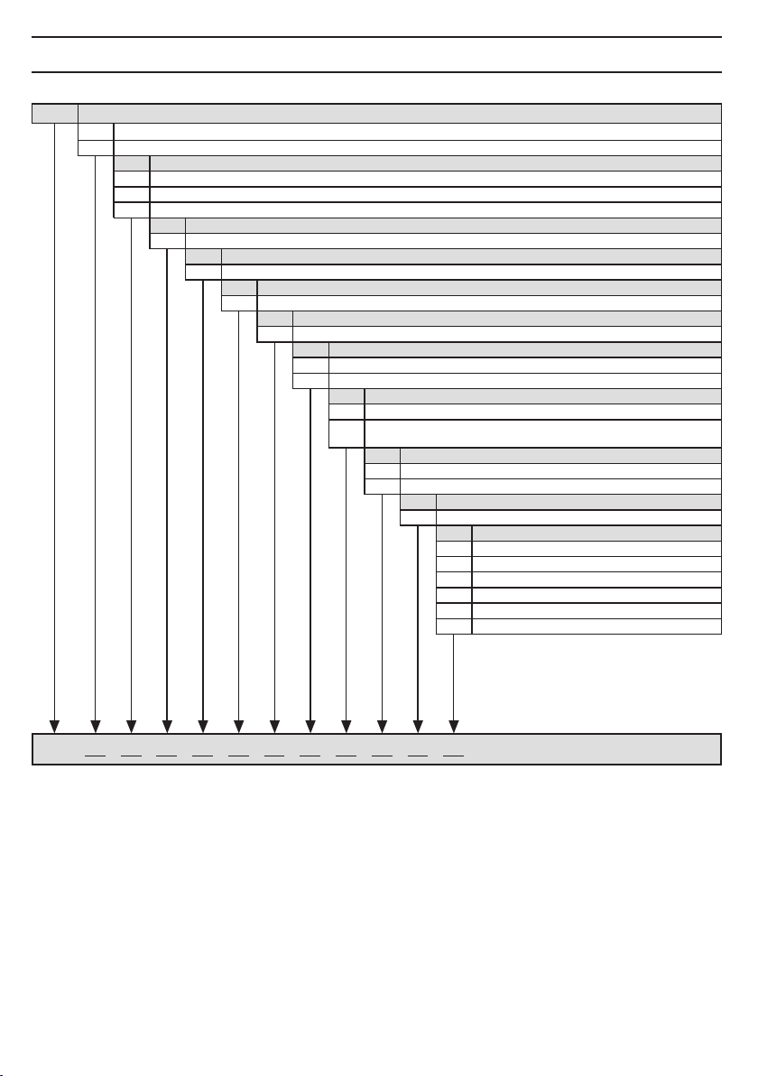
1 Device Identification / Identity Code
D2C A DULCOMETER® controller Series D2C
W Wall mounting
D Panel mounting (96 x 96 mm)
Operating voltage
0 230 V 50/60 Hz
1 115 V 50/60 Hz
4 24 V AC/DC
Measured variable 1/Measured variable 2
CC Chlorine/Chlorine (0...2/5/10 ppm)
Connection of measured variable 1 (connection measured variable 2: 4-20 mA)
1 Terminal standard signal 4–20 mA (signal converters are necessary)
Correction variable (Temperature for pH)
0 None
0 None
Disturbance variable connection
Signal output
0 None
42 Standard signal outputs 0/4-20 mA, free programmable
Power control
G Alarm and 2 limit relay
M Alarm and 2 solenoid valve relays
(pulse length control)
Control characteristic
1 Proportional control
2 PID control
0 None
Protocol output
Language
D German
E English
F French
S Spanish
A Swedish
N Dutch
D2C A
2
Please enter the identity code of your device here!
Page 3

2 General User Information
Page
1 Device Identification / Identity Code ...................................................................................................... 2
2 General User Information ......................................................................................................................... 3
3 Device Overview / Controls ..................................................................................................................... 4
4 Functional Description ............................................................................................................................ 5
5 Display Symbols ..................................................................................................................................... 6
6 Operating ................................................................................................................................................. 7
7 Operating Menu / Overview ..................................................................................................................... 8
8 Operating Menu / Description ............................................................................................................... 12
9 Technical Terms ..................................................................................................................................... 22
10 Faults / Notes / Troubleshooting ........................................................................................................... 23
General User Information
These operating instructions describe the technical data and function of the series DULCOMETER® D2C
controller, provide detailed safety information and are divided into clear steps.
IMPORTANT
• Please observe the parts of these operating instructions applicable to your particular
version! This is indicated in the Section “Device Identification/Identity Code”.
• Correct measuring and dosing is only possible in the case of impeccable operation of the
probe. The probe has to be calibrated/checked regularly!
• In the event of a probe failure, uncontrolled chemicals addition may result. We therfore
recommend urgently to activate “check out time limits” with automatic control shut-off!
3
Page 4
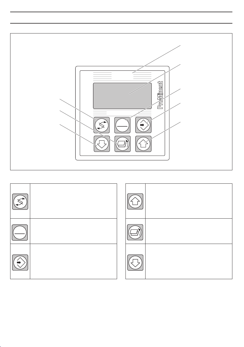
3 Device Overview / Controls
"Change"
button
"Branch back"
button
"Down"
button
DULCOMETER
CI2/CI
STOP
START
Display field
Measured variable
chlorine/chlorine
Graphic display
2
®
®
"Start/Stop"
button
"Enter"
button
"Up"
button
D2C2-002-chlorine/chlorine-GB
4
STOP
START
CHANGE button
To change over within a menu level
and to change from one variable to
another within a menu point.
START/STOP button
Start/stop of control and metering
function.
ENTER button
To accept, confirm or save a displayed
value or status. For alarm acknowledgement.
UP button
To increase a displayed numerical value
and to change variables (flashing
display)
BRANCH BACK button
Back to permanent display or to start
of relevant setting menu.
DOWN button
To decrease a displayed numerical
value and to change variables (flashing
display).
Page 5

4 Functional Description
NOTE
Please refer to the description of the operating menu for a detailed description of the
individual characteristics of the DULCOMETER
4.1 Operating Menu
The DULCOMETER® D2C controller permits settings to be made in two different menus. All values are
preset and can be changed in the complete operating menu.
The controller is delivered with a restricted operating menu so that the D2C controller can be used
effectively in many applications from the very onset. If adaptations prove to be necessary, all relevant
parameters can then be accessed by switching over to the complete operating menu.
4.2 Access Code
Access to the setting menu can be prevented by setting up an access code. The D2C controller is supplied
with the access code 5000 which permits free access to the setting menu. The calibration menu remains
freely accessible even when access to the setting menu is blocked by the code.
4.3 Control
The D2C can operate as a proportional controller or as a PID controller - dependent on the device version
(see identity code) and the setting.
The controlled variable is recalculated once a second. Control procedures which require rapid correction of
setpoint deviations (less than approx. 30 seconds) cannot be processed with this controller. The solenoid
valve control (pulse on-time) must take account of the cycle times.
The control function (reference variable output) can be switched off through the pause function and the
water control input. The calculation of the regulated variable starts again with the cessation of the "pause"
after expiry of the adjustable delay time "td". No fault treatment is performed with active "pause" function.
®
D2C controller!
4.4 Fault messages
Faults to be acknowledged are shown in the permanent displays by the symbol "
fault messages and notes are shown in the permanent display 2. Faults/notes continuing after
acknowledgement are shown alternatively. Faults automatically remedied throught changing operating
conditions are removed from the permanent display without necessitating acknowledgement. Chapter 10
includes an overview of fault messages and causes.
". The corresponding
5
Page 6
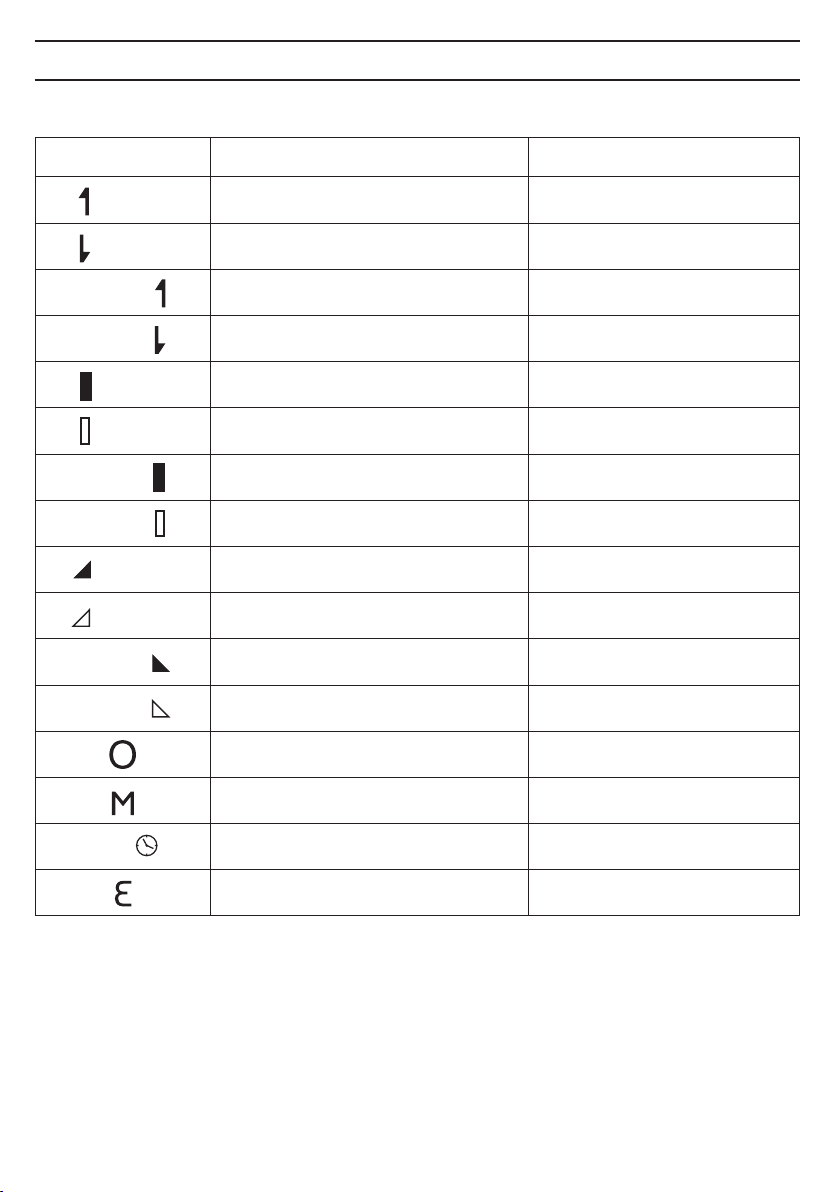
5 Display Symbols
The display of the DULCOMETER® D2C controller uses the following symbols:
Symbol Description Comment
Limit value transgression measured value 1
Relay 1 upper or zone left
Relay 1 lower left
Limit value transgression measured value 2
Relay 2 upper or zone right
Relay 2 lower right
Metering pump measured value 1 Symbol
Control off left
Control on left
Metering pump measured value 2 Symbol
Control off right
Controll on right
Solenoid valve measured value 1 Symbol
Controll off left
Controll on left
Solenoid valve measured value 2 Symbol
Controll off right
Control on right
Stop button pressed
Symbol
Symbol
Symbol
Symbol
Symbol
Symbol
Symbol
Symbol
pause
6
Manual metering
Delay time "td" Control starts after
expiry of "td"
Fault
Page 7

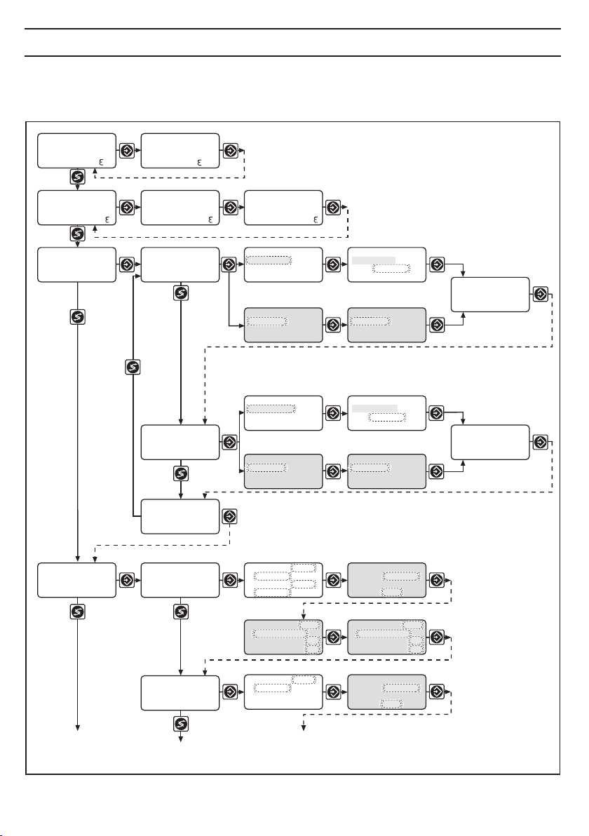
6 Operation
Permanent
display 1
Permanent
display 3
Calibration
menu
Various
Setting menus
Access code
NOTE
Access to the setting menus can be barred with the access code!
The number and scope of setting menus is dependent on the device version!
If the access code is selected correctly in a setting menu, then the following setting menus are also
accessible!
If within a period of 10 minutes no button is pushed, the unit automatically branches back from the
calibrating menu or a setting menu to the permanent display 1.
Permanent
display 2
Permanent
display 4
Calibration notes
Access code, correct
Parameter
setting
The various menus are
selected with the CHANGE
button
The menu is started with
the ENTER button
BRANCH BACK to
permanent display or to
relevant setting menu
D2C2-007-chlorine/chlorine GB
BRANCH BACK without
saving setting
BRANCH BACK to
start of setting
Variables flash
Text 1
Selection 1
Text 2
Selection 2
Text 1
Selection 1
Text 2
Selection 2
CHANGE from selection to selection
Change numbers or
settings of selection
ENTER and save setting,
continue to next menu
D2C2-008-chlorine/chlorine-GB
7
Page 8
7 Operating Menu / Overview
The setting menus highlighted in grey and the adjustable parameters are only visible in the complete
operating menu.
0.50
0.20
free CL 0.50 ppm
s. point 0.40 ppm
ctrlout 50 %
calibration ?
ppm o
CLE
ppm
∆Cl
free CL 0.50 ppm
comb. CL 0.20 ppm
total CL 0.70 ppm
stop key
comb. CL 0.20 ppm
s.point 0.20 ppm
ctrlout 0 %
cal. free chlor.
zero p.: 4.00 mA
slope:
6.00 mA/ppm
cal. total chlor.
zero p.: 4.00 mA
slope:
6.00 mA/ppm
calibration
end
total CL 0.70 ppm
cal. free chlor.
DPD1-value
0.45 ppm
cal. free chlor.
zero point
0.45 ppm
cal. total chlor.
DPD4-value:
0.45 ppm
cal. total chlor.
zero point
1.28 ppm
cal. free chlor.
DPD1-value
0.45 ppm
cal. free chlor.
zero point
value take over?
4.01 mA
cal. total chlor.
DPD4-value
0.45 ppm
cal. total chlor.
zero point
value take over?
4.01 mA
cal. free chlor.
zero p.: 4.00 mA
slope:
6.01 mA/ppm
cal. total chlor.
zero p.: 4.00 mA
slope:
6.01 mA/ppm
8
limits
setting ?
limit
free chlorine
limit
comb. chlorine
limit 2: upper
0.60 ppm
limit 1: lower
0.10 ppm
LV-relay 1: LV1
- active closed
∆t on 0 s
∆t off 0 s
limit 2: upper
0.10 ppm
hysteresis
limits: 0.04 ppm
checkout time
limits: off
Only with limit value relay
LV-relay 2: LV2
- active closed
∆t on 0 s
∆t off 0 s
hysteresis
limits: 0.04 ppm
checkout time
limits: off
Page 9

Operating Menu / Overview
control
setting ?
limit
total chlorine
limit
end
control
free chlorine
LV-relay 2: LV2
- active closed
∆t on 0 s
∆t off 0 s
limit 2: upper
0.60 ppm
limit 1: lower
0.10 ppm
LV-relay 1: LV1
- active closed
∆t on 0 s
∆t off 0 s
control
automatic
dosing direction
free chlorine
ctrl parameter
xp = 10 %
Ti= off
Td= off
LV-relay max.
time: 0000 s
hysteresis
limits: 0.04 ppm
checkout time
limits: off
Only with limit value relay
LV-relay 2: LV2
- active closed
∆t on 0 s
∆t off 0 s
set point
value: 0.40 ppm
dosing direction
free chlorine
set point 2 upper
value: 0.40 ppm
set point 1 lower
value: 0.40 ppm
manual dosing
value: 0 %
dosing direction
free chlor.
additional load
value: 0 %
dosing direction
free chlorine
control
comb. chlorine
control
end
control
automatic
dosing direction
comb. chlorine
ctrl parameter
xp = 10 %
Ti= off
Td= off
set point
value: 0.20 ppm
dosing direction
comb. chlorine
manual dosing
value: 0 %
dosing direction
comb. chlorine
additional load
value 0 %
dosing direction
comb. chlorine
9
Page 10

Operating Menu / Overview
pumps
setting ?
relay
setting ?
measuring range
setting ?
meas. value free
chlorine setting
pump 1
pump 2
pump end
relay 1
relay 2
relay end
free chlorine
0...2.00 ppm
total chlorine
0...2.00 ppm
free chlorine
range adjustment
4 mA = 0.00 ppm
20 mA = 2.00 ppm
pump 1
- free chlorine
pump 2
- comb. chlorine
relay 1
- free chlorine
relay adjustment
- solenoid valve
relay 2
- comb. chlorine
relay adjustment
- solenoid valve
pump
- free chlor.
dosing pump max.
pulse/min: 180
pump
- comb. chlor.
dosing pump max.
pulse/min: 180
solenoid valve 1
- free chlor.
period 10 s
min. time 1 s
solenoid valve 2
- comb. chlor.
period 10 s
min. time 1 s
10
mA outputs
setting ?
mA output 1
mA output 2
mA output end
mA output 1
- free chlorine
adjustment
-
measured value
mA output 2
- comb. chlorine
adjustment
- control output
mA output 1
0 mA = 0.00 ppm
20 mA = 2.00 ppm
mA output 2
4 mA = 0 %
20 mA = 100 %
Page 11

Operating Menu / Overview
general setting
information
ident-code: D2CA
M0CC1004M20A
software version
D2C-Cl FW-01.00
pause free Cl
- active closed
- alarm off
- td: 10 min.
access c.: 5000
operating menu:
- english
- complete
alarm relay
active
pause total Cl
- active closed
- alarm off
- td: 10 min.
Permanent display 1
11
Page 12

8 Operating Menu / Description
Permanent displays
0.50
0.20
free CL 0.50 ppm
s. point 0.40 ppm
ctrlout 50 %
ppm o
CLE
ppm
∆Cl
free CL 0.50 ppm
comb. CL 0.20 ppm
total CL 0.70 ppm
stop key
comb. CL 0.20 ppm
s.point 0.20 ppm
ctrlout 0 %
total CL 0.70 ppm
The permanent displays 1 to 4 serve information on fault messages/causes (see also table on page 23) as
well as on operating values/settings.
Calibrate
The chlorine probe is calibrated (slope adjustment) using the DPD method (free chlorine: DPD1, total
chlorine: DPD1+3 or DPD4). The frozen measured value is suggested at the start of the calibration; this can
be adjusted to the measured DPD value with the up / down keys. A calibration is only possible if the DPD
value is ≥ 2% of the range. The control function stops during the calibration and the dosing goes over to
base load. After a successful calibration, the error diagnostics related to the measured value are restarted.
In the complete operating menu, the zero can be adjusted as well as the slope. The zero adjustment must
be made under realistic operating conditions with chlorine-free water! In this case control is stopped and
the dosing is reduced to the set base load.
The 0/4 ... 20 mA output (measured value) is frozen at the start of the calibration.
ATTENTION
• The range of the chlorine measuring cell must match the set range of the DULCOMETER® D2C
(factory setting 0 - 2.00 ppm). Any range adjustment (see “Measuring ranges” and “Free
chlorine measured value” sections, Page 19) must be made before the calibration. When
the range is changed, all settings are reset to the factory settings.
• The D2C Cl
maintains the pH at a constant value with a maximum deviation of Xm = 0.05 pH! Only then
/Cl2 must only be operated in conjunction with a pH control system which
2
can the D2C Cl2/Cl2 control the chlorine concentration with sufficient accuracy, as the
chlorine measured value is pH-dependent.
12
Page 13

Operating Menu / Description
calibration ?
cal. free chlor.
zero p.: 4.00 mA
slope:
6.00 mA/ppm
cal. total chlor.
zero p.: 4.00 mA
slope:
6.00 mA/ppm
calibration
end
cal. free chlor.
DPD1-value
0.45 ppm
cal. free chlor.
zero point
0.45 ppm
cal. total chlor.
DPD4-value:
0.45 ppm
cal. total chlor.
zero point
1.28 ppm
cal. free chlor.
DPD1-value
0.45 ppm
cal. free chlor.
zero point
value take over?
4.01 mA
cal. total chlor.
DPD4-value
0.45 ppm
cal. total chlor.
zero point
value take over?
4.01 mA
cal. free chlor.
zero p.: 4.00 mA
slope:
6.01 mA/ppm
cal. total chlor.
zero p.: 4.00 mA
slope:
6.01 mA/ppm
Possible values
Initial value Increment Lower value Upper value
DPD value Measured value 0.01 ppm -0.20 ppm 2.20 ppm
0.01 ppm -0.50 ppm 5.50 ppm
0.01 ppm -1.00 ppm 11.00 ppm
Zero point Measured value (mA) – – –
Error message Condition Remarks
Cl calibration not possible! Cl slope too low Repeat calibration
Slope too low (<25 % of the standard slope)
Cl calibration not possible! Cl slope too high Repeat calibration
Slope too high (>300 % of the standard slope)
DPD value too small! DPD <2 % of measuring range Repeat calibration after
DPD > x.xx ppm addition of chlorine
Zero point high Sensor signal > 5 mA Repeat calibration in
chlorine-free water
Zero point low Sensor signal < 3 mA Check sensor connection
Possibly change sensor
13
Page 14

Operating Menu / Description
Limits
When setting the check out time, metering of the corresponding pump is stopped and an alarm is triggered
through the alarm relay in the event of limit violations exceeding the set check out time.
For devices with limit relays, a limit value or a zone may be set for each measuring value, where the relay will
switch.
limits
setting ?
limit
free chlorine
limit
comb. chlorine
limit
total chlorine
limit
end
limit 2: upper
0.60 ppm
limit 1: lower
0.10 ppm
LV-relay 1: LV1
- active closed
∆t on 0 s
∆t off 0 s
limit 2: upper
0.10 ppm
LV-relay 2: LV2
- active closed
∆t on 0 s
∆t off 0 s
limit 2: upper
0.60 ppm
limit 1: lower
0.10 ppm
LV-relay 1: LV1
- active closed
∆t on 0 s
∆t off 0 s
hysteresis
limits: 0.04 ppm
checkout time
limits: off
Only with limit value relay
LV-relay 2: LV2
- active closed
∆t on 0 s
∆t off 0 s
hysteresis
limits: 0.04 ppm
checkout time
limits: off
LV-relay max.
time: 0000 s
hysteresis
limits: 0.04 ppm
checkout time
limits: off
Only with limit value relay
LV-relay 2: LV2
- active closed
∆t on 0 s
∆t off 0 s
14
Page 15

Operating Menu / Description
Initial value Step interval Lower value Upper value Remarks
Type of limit infringement Limit infringement when value
Free chlorine upper upper
Combined chlorine lower upper
Total chlorine upper upper
Limit value 1 0.10 ppm 0.01 ppm -0.20 ppm 2.20 ppm
0.25 ppm 0.01 ppm -0.50 ppm 5.50 ppm
0.50 ppm 0.01 ppm -1.00 ppm 11.00 ppm
Limit value 2 0.60 ppm 0.01 ppm -0.20 ppm 2.20 ppm
1.50 ppm 0.01 ppm -0.50 ppm 5.50 ppm
3.00 ppm 0.01 ppm -1.00 ppm 11.00 ppm
Hysteresis limit 0.04 ppm 0.01 ppm 0 ppm 2.20 ppm Works towards clearing the
0.10 ppm 0.01 ppm 0 ppm 5.50 ppm infringement of the limit.
0.20 ppm 0.01 ppm 0 ppm 11.00 ppm
Checkout time limit Off 1 s 1 s 9999 s Leads to message and alarm
Limit relay 1 LV-relay 1 LV-relay 1
Limit relay 2 LV-relay 1 LV-relay 1
Limit relays 1, 2 active active
closed closed
Turn-on delay ∆t On 0 s 1 s 0 s 9999 s
Turn-off delay ∆t Off 0 s 1 s 0 s 9999 s
Limit relay Off 1 s 1 s / Off 9999 s Function can be switched off
max. (turn-on) time
Possible values
exceeds or falls below limit
lower
lower
lower
and shutdown of the
corresponding dosing.
Off: function switched off,
no message, no alarm.
LV-relay 2
Zone* *With the “Zone” setting
Off the gap between the limits
must be ≥ 3 times the set
LV-relay 2
Zone*
Off
active
open
hysteresis.
15
Page 16

Operating Menu / Description
Control
control
setting ?
control
free chlorine
control
dosing direction
free chlorine
automatic
set point
value: 0.40 ppm
dosing direction
free chlorine
set point 2 upper
value: 0.40 ppm
set point 1 lower
value: 0.40 ppm
manual dosing
value: 0 %
dosing direction
free chlor.
additional load
value: 0 %
dosing direction
free chlorine
set point
value: 0.20 ppm
dosing direction
comb. chlorine
manual dosing
value: 0 %
dosing direction
comb. chlorine
additional load
value 0 %
dosing direction
comb. chlorine
control
comb. chlorine
control
end
ctrl parameter
xp = 10 %
Ti= off
Td= off
control
automatic
dosing direction
comb. chlorine
ctrl parameter
xp = 10 %
Ti= off
Td= off
Possible values
Initial value Step interval Lower value Upper value Remarks
Control automatic automatic
auto with dead zone
manual
off
Dosing direction free chlorine free chlorine
free chlorine
free chlorine /
Setpoint 1/2 0.40 ppm 0.01 ppm 0 ppm 2.00 ppm setpoint1 ≤ setpoint2
1.00 ppm 0.01 ppm 0 ppm 5.00 ppm
2.00 ppm 0.01 ppm 0 ppm 10.00 ppm
16
Page 17

Operating Menu / Description
Possible values
Initial value Step interval Lower value Upper value Remarks
Control parameter xp 10 % 1 % 1 % 500 % xp relative to measuring
Control parameter Ti Off 1 s 1 s 9999 s
Control parameter Td Off 1 s 1 s 2500 s
Additive base load 0 % 1 % 0 % +100 %
Manual dosing 0 % 1 % -100 % +100 %
(free chlorine)
Manual dosing
(combined chlorine) 0 % 1 % 0 % +100 %
Pumps
The maximum stroke value of the metering pumps should correspond to the stroke frequency of the
metering pump used.
range
pumps
setting ?
pump 1
pump 2
pump end
pump 1
- free chlorine
pump 2
- comb. chlorine
pump
- free chlor.
dosing pump max.
pulse/min: 180
pump
- comb. chlor.
dosing pump max.
pulse/min: 180
Possible values
Initial value Step interval Lower value Upper value Remarks
Assignment of
measured variables
Pump 1 free chlorine free chlorine
combined chlorine
Off
Pump 2 combined chlorine free chlorine
combined chlorine
Off
Dosing direction free chlorine free chlorine Selection only available
Pump free chlorine with free chlorine
Max. no. of strokes/min 180 1 1 500 Off = 0 strokes/min
of pumps 1 and 2
17
Page 18

Operating Menu / Description
Relays
The two relays can be freely assigned with regard to function (limit, correcting element, solenoid valve).
If the function is set to correcting element or solenoid valve, the relays are de-energised on fault to prevent
faulty dosing.
Relay output 2 for combined chlorine is used to control devices for minimising combined chlorine.
relay
setting ?
relay 1
relay 2
relay end
relay 1
- free chlorine
relay adjustment
- solenoid valve
relay 2
- comb. chlorine
relay adjustment
- solenoid valve
solenoid valve 1
- free chlor.
period 10 s
min. time 1 s
solenoid valve 2
- comb. chlor.
period 10 s
min. time 1 s
Possible values
Initial value Increment Lower value Upper value Remarks
Measured variable
assignment
Relay 1 free chlorine free chlorine
comb. chlorine
total chlorine
Off
Relay 2 comb. chlorine free chlorine
comb. chlorine
total chlorine
Off
Function in accordance with limit value
1)
not with total chlorine
assignment Identity Code correcting element * measured variable
Relay solenoid valve
1)
* e.g. motor-driven pump
Relay is de-energised
on fault and during
the calibration
Dosing direction free chlorine free chlorine Selection only available
Solenoid valve 1 free chlorine with free chlorine
Cycle time 10 s 1 s 10 s 9999 s
Minimum time 1 s 1 s 1 s cycle/2
18
Page 19

Operating Menu / Description
Measuring ranges
ATTENTION
• The ranges (factory setting 0 – 2.00 ppm) must match the ranges of the chlorine measuring
cells used.
• If the range is changed, all settings (limits, setpoints ....) are reset to the factory settings!
measuring range
setting ?
free chlorine
0...2.00 ppm
total chlorine
0...2.00 ppm
Possible values
Initial value Increment Lower value Upper value Remarks
Measuring range 0...2 ppm 0...2 ppm
0...5 ppm
0...10 ppm
Free chlorine measured value
The measurement signal for free chlorine is connected to the standard signal input of X2. As the
measurement signal can come from an external device or a D1C with a different range, you can adjust the
range of this standard signal input separately in this setting menu.
ATTENTION
• If the range is changed, all setting values must be checked!
• If the measurement signal does not come directly from a sensor, but comes from a device
such as a D1C, for example, only the ranges of the D2C and the device have to be matched
to one another – do not calibrate the D2C for free chlorine!
• If the range changes, the controller range also changes with it!
meas. value free
chlorine setting
free chlorine
range adjustment
4 mA = 0.00 ppm
20 mA = 2.00 ppm
Possible values
Initial value Step interval Lower value Upper value Remarks
Lower limit of 4 mA 4 mA Upper limit is 20 mA
standard signal range 0 mA
Range assigned 0...2.00 ppm 0.01 ppm -0.20 ppm 2.20 ppm
to the standard 0...5.00 ppm 0.01 ppm -0.50 ppm 5.50 ppm
signal 0...10.00 ppm 0.01 ppm -1.00 ppm 11.00 ppm
19
Page 20

Operating Menu / Description
Outputs 0/4 - 20mA
The mA outputs may be used either for documentation of the measuring value or as regulated value. When
the regulated value is set, the metering direction selected in "control" will be automatically used!!
mA outputs
setting ?
mA output 1
mA output 2
mA output end
mA output 1
- free chlorine
adjustment
measured value
-
mA output 2
- comb. chlorine
adjustment
- control output
mA output 1
0 mA = 0.00 ppm
20 mA = 2.00 ppm
mA output 2
4 mA = 0 %
20 mA = 100 %
Possible values
Initial value Increment Lower value Upper value Remarks
Measured variables
assignment
mA output 1 free chlorine free chlorine
comb. chlorine
total Cl
Off
mA output 2 comb. chlorine free chlorine
comb. chlorine
total Cl
Off
Functions measured value
assignment control variable
1)
1)
not with total chlorine
measured variable
output1 measured value
output2 measured value
Lower limit 4 mA 4 mA Upper limit is 20 mA
Standard signal range 0 mA
Measured value
range 0…2 ppm 0.01 ppm -1.00 ppm 11.00 ppm Minimum range 0.1 ppm
Control variable range 0 %…+100 % 1 % 0 % +100 % Minimum range 1 %
20
Page 21

Operating Menu / Description
General settings
Alarm relay
The alarm relay may be activated / deactivated. When deactivated, no fault message is displayed.
Pause function
With regard to the pause, a delay time "td" may be set. The control will start again only after cessation of the
pause contact and expiry of the preset delay time. When the delay time is elapsing, a clock symbol will be
displayed. The pause function may be reset by pressing the start / stop button.
The mA output measuring value will be frozen when the pause function is activated.
Operating menu
All setting menus may be accessed by switching from reduced to complete. We recommend to set the
reduced menu again after commissioning.
Access code
If the access code (factory-set to 5000) is altered, no settings (with the exception of cali-bration) may be
carried out without entering the correct code.
general setting
information
ident-code: D2CA
M0CC1004M20A
software version
D2C-Cl FW-01.00
pause free Cl
- active closed
- alarm off
- td: 10 min.
access c.: 5000
operating menu:
- english
- complete
alarm relay
active
pause total Cl
- active closed
- alarm off
- td: 10 min.
Permanent display 1
Possible values
Initial value Increment Lower value Upper value Remarks
Alarm relay active active
not active
Pause closed closed
open
Alarm off Alarm off
Alarm on
td: 10 min 1 min 0 min 60 min
Access code 5000 1 1 9999
Language as per identity German
code Englisch
French
Spanish
Swedish
Dutch
Operating menu restricted restricted
complete
21
Page 22

9 Technical Terms
Calibration: By calibrating (adjusting), the measuring value readout will be adjusted to the actual
Solenoid valve: Activation of solenoid valves (motor-driven pumps) is defined by the cycle time and
Zero point: The zero point of pH probes is theoretically 0 mV. In practice, for a good probe
Slope: The slope of pH probes should always be ≥ 50 (better: ≥ 55) mV/pH. The slope of the
Set point: The set point is the value which is to be continuously maintained stable throughout
Regulated value: The regulated value is the value (e.g. frequency, mA signal) the controller sends to the
Control parameter: The control parameters (xp, Ti, Td) determine the control characteristic (PID).
Manual control: In this setting, the controller produces a controlled variable corresponding to the
xp value: This value influences the proportional control behaviour. In case of a deviation of 1.4
Ti (integral This value defines the integral (I) control behaviour. The greater Ti, the lower the
action time): I proportion.
Td (differential This value defines the differential (D) control behaviour. The lower Ti, the lower the
action time): D proportion.
Metering direction: This value determines in which direction the controller is active. In case of the
Additive base load: This results in the fact that the controller always generates a manipulated value
Relay: The relay (alarm, limit relay) switch when the corresponding prerequisites (e.g. alarm
probe signal. Without calibration, a correct measurement is not possible. A calibration
should be performed regularly (depending on application).
the minimum on-state interval (minimum time) (pulse length control). The on-state
interval always corresponds to at least the minimum time. However, it is increased up
to the cycle time at a maximum depending on the control deviation and the control
response. The cycle time itself defines the maximum possible on-state operations.
For instance, an actuator is switched on a maximum of 60 times per hour when the
cycle time is at 60 seconds. The minimum time defines the minimum on-state interval
duration. It should be selected as small as possible while, however, ensuring that
metering is still possible within this time.
function a zero point of ± 25 mV is acceptable.
The zero point of chlorine probes is 4 mA. A calibration is not necessary.
chlorine measuring cell is given in mA/ppm. For a good probe function, the values
accepted by the controller are sufficient.
the process via controlling.
final controlling element (e.g. metering pump) to reach again the set point.
entry. It is retained up to the next change. It is independent of the measured variable
and the set control parameters. This setting can be used for determining the time
response (e.g. dead time...) of the controlled system.
pH (=10 % of 14 pH) or 0.2 ppm (=10 % of 2 ppm), a xp value of 10 %, for example,
leads to a regulated value of 100 %. If the xp value has to be increased to 20 %, the
deviation must be double the value in order to reach a regulated value of 100 %. In
case of control overshooting, the set xp value must be doubled.
metering direction "acid", the controller generates a manipulated value when the
specified value for pH is exceeded.
corresponding to the additive base load. This load may only be reset to 0 using the
stop button. This function should not be activated when using PI or PID controllers.
condition, limit violation) are given. The relay function can be set either as make
contact (active closed) or break contact (active open). The relay may be reset pressing
the stop button. (Exception: limit value).
22
Page 23

10 Faults / Notes / Troubleshooting
2)
3)
5)
the dosing for combined chlorine goes onto base load as well (except for limit infringement)
the control for combined chlorine stops as well (except for limit infringement)
the delay period td of the pause function is deleted
Electronics error EEPROM faulty none stop Yes Return device
Operating step Info text Symbol Effect Alarm with Remarks Remedy
Pause contact pause none stop Yes, Delay time td Deselect pause,
Stop key
5)
Limit infringement comb CI limit
after check time switched off
Faulty calibration cal. total CI base load
Combined chlorine comb CI negativ continues No < -10 % Optimise pH controller,
negative value of measuring range recalibrate free Cl
after check time total CI limit
Faulty calibration cal. free CI base load
Total chlorine
signal too high total CI inputa base load
/ too low transmitter and connection
Limit infringement total CI limit
Free chlorine
signal too high free CI inputaaa base load
/ too low transmitter and connection
Limit infringement free CI limit
after check time free CI limit
Error Error text Symbol Effect Alarm with Remarks Remedy
switchable adjustable: shows delay time td
current „td“
stop key none stop No Start device
on dosing on control acknowledge
2 /
a none stop Yes Function can be
and total Cl
not possible! possibly renew.
1 /
2 /
aaa none stop
aaa switched off
2)
stop
3)
3)
Yes function can be
No Check sensor, clean,
Repeat calibration
not possible! possibly renew.
2)
stop
3)
Yes 3 mA>signal>23 mA Check sensor,
Repeat calibration
1 /
2 /
aaa none stop
aaa switched off
2)
stop
3)
No Check sensor, clean,
2)
stop
3)
3)
Yes 3 mA>signal>23 mA Check sensor,
Yes Function can be
on dosing on control acknowledge
23
Page 24

24
'
©2005 ProMinent Dosiertechnik GmbH · 69123 Heidelberg · Germany
Operating Instructions DULCOMETER® D2C, Part 2, Chlorine/Chlorine
Subject to modifications · Printed in Germany
Addresses and delivery information may be obtained from the manufacturer:
ProMinent Dosiertechnik GmbH · Im Schuhmachergewann 5-11 · 69123 Heidelberg
Telephone: +49 6221 842-0 · Telefax: +49 6221 842-419
info@prominent.com · www.prominent.com
 Loading...