

Page 1
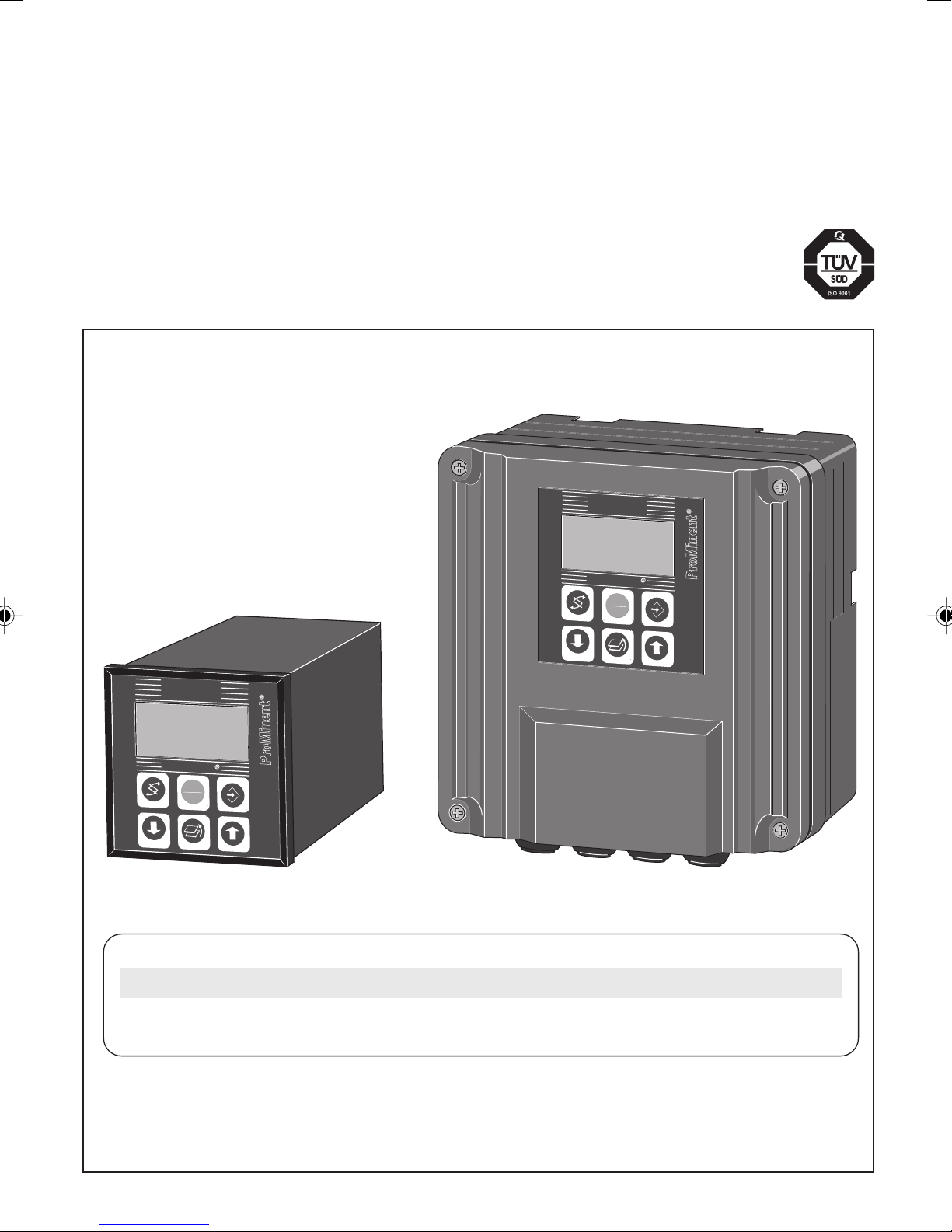
Operating Instructions
DULCOMETER® D1C
Part 2: Adjustment and Operation
Measured variable inductive conductivity
®
ProMinent
D1C2-cond.-001-D
Conductivity
100
DULCOMETER
STOP
START
µ
S/cm
Conductivity
100
DULCOMETER
STOP
START
Type WType D
µs/cm
D1C A
___ ___ ___ ___ ___ ___ ___ ___ ___ ___ ___ ___ ___
Please enter the identity code of your device here.
Please completely read through the operating instructions! · Do not discard!
The warranty shall be invalidated by damage caused by operating errors!
Part No. 986954 ProMinent Dosiertechnik GmbH · 69123 Heidelberg · Germany BA DM 138 09/06 GB
Page 2
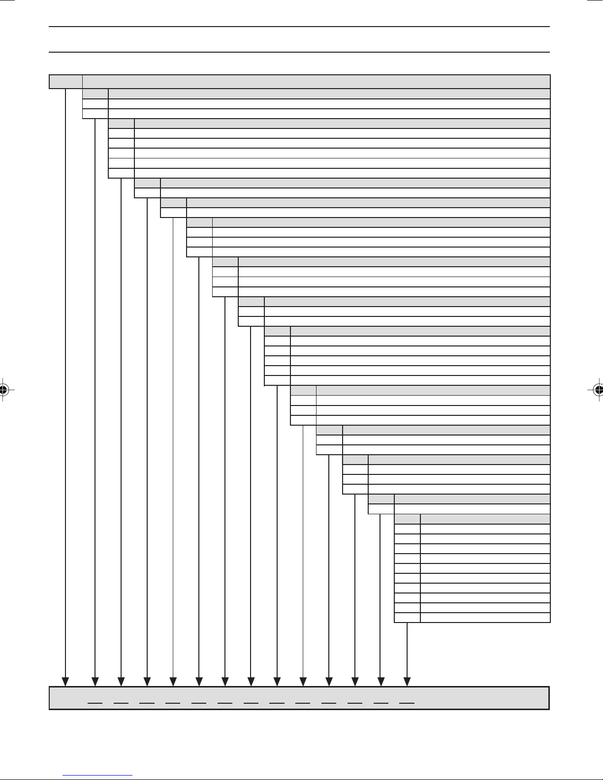
1 Device Identification / Identity Code
D1C A DULCOMETER® Controller Series D1C / Version A
Type of mounting
D Control panel installation 96 x 96 mm
W Wall mounting
Operating voltage
0 230 V 50/60 Hz
1 115 V 50/60 Hz
2 200 V 50/60 Hz (only with control panel installation)
3 100 V 50/60 Hz (only with control panel installation)
4 24 V AC/DC
Measured variable
L Conductivity
Connection of measured variable
6 Inductive terminal conductivity measurement cells (0-20/200/2000 µS/cm; 0-20/200/2000 mS/cm)
Correction variable
0 None
2 Temperature via terminal (Pt100)
4 Manual temperature input
Feed forward control
0 None
4 Flow as 0/4-20 mA standard signal and parameter record switching
5 Parameter record switching
Control input
0 None
1 Pause
Signal output
0 None
1 Standard signal 0/4-20 mA measured value
2 Standard signal 0/4-20 mA control variable
3 Standard signal 0/4-20 mA correction variable
42 standard signal 0/4-20 mA outputs, free programmable
Power control
G Alarm and 2 limit value relays
M Alarm and 2 solenoid valve relays
R Alarm relay and servomotor with feedback
0 None
2 Two pumps
Pump control
Control characteristic
0 None
1 Proportional control
2 PID control
Log output
0 None
Language
D German
E English
F French
I Italian
N Dutch
S Spanish
PPolish
ASwedish
B Portuguese
H Hungarian
D1C A
Please enter the identity code of your device here!
2
Page 3
2 General User Information
Page
1 Device Identification / Identity Code .................................................................................................... 2
2 General User Information ...................................................................................................................... 3
3 Device Overview / Controls................................................................................................................... 4
4 Functional Description .......................................................................................................................... 5
5 Display Symbols .................................................................................................................................... 6
6 Operation diagram ................................................................................................................................ 7
7 Restricted Operating Menu ................................................................................................................... 8
General Layout ............................................................................................................................. 8
Description ................................................................................................................................... 9
8 Complete Operating Menu .................................................................................................................. 13
Overview ..................................................................................................................................... 13
Description ................................................................................................................................. 14
9 Fault/Remarks/Troubleshooting ......................................................................................................... 28
General User Information
These operating instructions describe the technical data and function of the series DULCOMETER® D1C
controller, provide detailed safety information and are divided into clear steps.
IMPORTANT
• Please observe the parts of these operating instructions applicable to your particular
version! This is indicated in the Section “Device Identification / Identity Code”!
• Correct measuring and metering is only possible in the case of impeccable operation of
the sensor. The sensor has to be calibrated / checked regularly!
NOTE
A form “Documentation of controller settings type D1C” is available under
www.prominent.com/documentation_D1C for the purpose of documenting the controller
settings.
3
Page 4
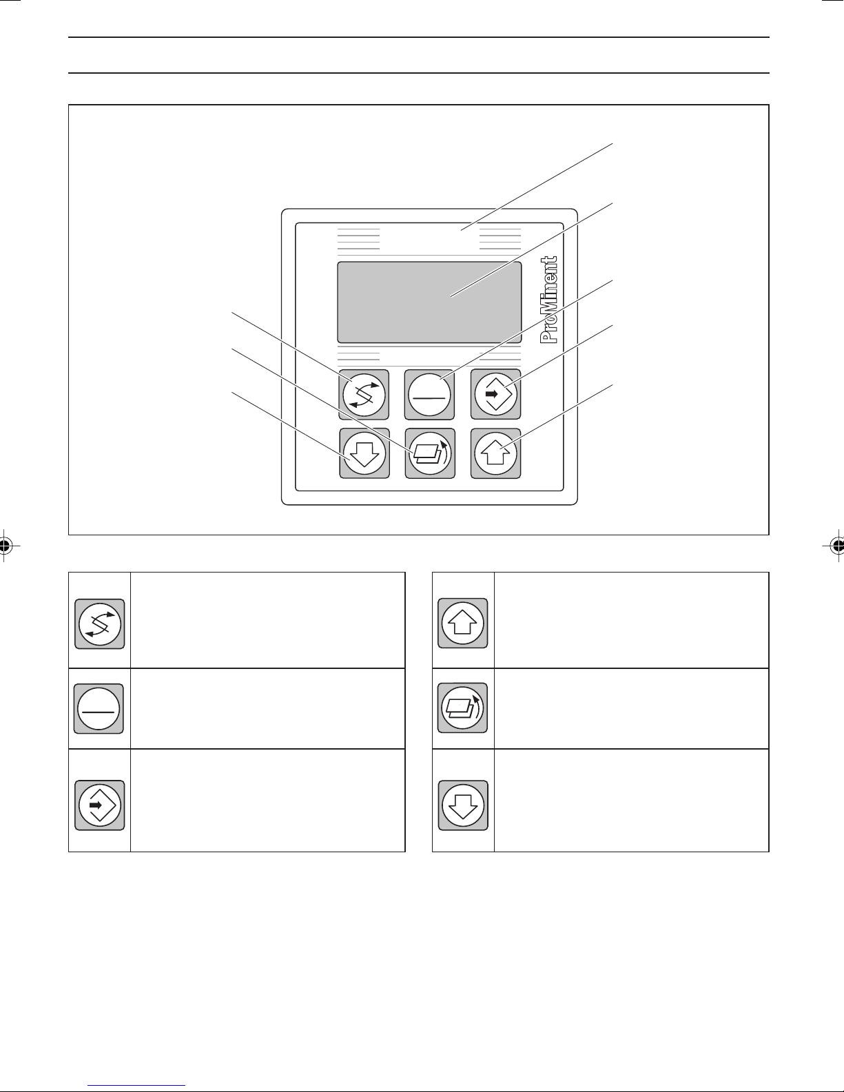
3 Device Overview / Controls
Conductivity
"Change"
Button
"Branch back"
Button
"Down"
Button
DULCOMETER
STOP
START
Display field
Measured variable
inductive conductivity
Graphic
display
®
"Start/Stop"
Button
"Enter"
Button
®
"Up"
Button
STOP
START
CHANGE Button
To change over within a menu level
and to change from one variable to
another within a menu point.
START/STOP Button
Start/stop of control and metering
function.
ENTER Button
To accept, confirm or save a displayed value or status. For alarm
acknowledgement.
D1C2-cond.-002-D
UP Button
To increase a displayed numerical
value and to change variables (flashing
display).
BRANCH BACK Button
Back to permanent display or to start
of relevant setting menu.
DOWN Button
To decrease a displayed numerical
value and to change variables (flashing
display).
4
Page 5
4Functional Description
NOTE
Please refer to the description of the complete operating menu in Section 8 for a detailed
description of the individual characteristics of the DULCOMETER® D1C controller!
4.1 Operating Menu
®
The DULCOMETER
preset and can be changed in the complete operating menu.
The controller is delivered with a restricted operating menu so that the D1C controller can be used
effectively in many applications from the very onset. If adaptations prove to be necessary, all relevant
parameters can then be accessed by switching over to the complete operating menu (see “General
settings”).
4.2 Access Code
Access to the setting menu can be prevented by setting up an access code. The D1C controller is supplied
with the access code 5000 which permits free access to the setting menu. The calibration menu remains
freely accessible even if access to the setting menu is blocked by the code.
4.3 Control
The D1C can operate as a proportional controller or as a PID controller - depending on the device version
(see identity code) and the setting.
The controlled variable is recalculated once a second. Control procedures which require rapid correction of
setpoint deviations (less than approx. 30 seconds) cannot be processed with this controller. The cycle
times must be taken into consideration when activating solenoid valves (pulse length) in the same way as
their running times when activating servomotors (3-point).
Via the control input pause, the control function (selection of controlled variable) can be switched off. The
calculation of the controlled variable starts again after cessation of "pause".
D1C controller permits settings to be made in two different menus. All values are
4.4 Feed Forward Control
The D1C controller can process a signal of a feed forward control. Depending on the device version (see
identity code) and the setting, this signal can be obtained in any form of a 0–20 mA or 4–20 mA signal or as
a digital contact signal with the maximum frequencies 10 Hz or 500 Hz.
This signal can be used, for example, for flow-proportional metering (multiplicative effect) or feed forwarddependent basic load metering (additive effect). The result of control variable calculation from the
proportional or PID control is multiplied by or added to the feed forward signal. A multiplicative feed forward
variable at the level of the set rated value carries over the calculated control variable unchanged into the
controlled variable:
Controlled variable = Feed forward variable/rated value x calculated control variable
During start-up, the zero point has to be checked. The multiplicative feed forward control is not designed
for switching off permanently the actuating variable (signal ≈ 0).
An additive feed forward variable at the level of the rated value results in maximum controlled variable:
Controlled variable (max. 100 %) = Feed forward variable/rated value x max. controlled variable
+ calculated control variable
4.5 Error Messages
Error messages and information are indicated on the bottom line in the permanent display 1. Errors to be
acknowledged (acknowledgement switches off the alarm relay) are indicated by the "
". Errors/notes
which still apply after acknowledgement are indicated alternately. During correction variable processing
(temperature for correction of pH-value), the value is indicated in the same line as the error/note. Faults
which are rectified of their own accord due to changed operating situations are removed from the
permanent display without the need for acknowledgement.
5
Page 6
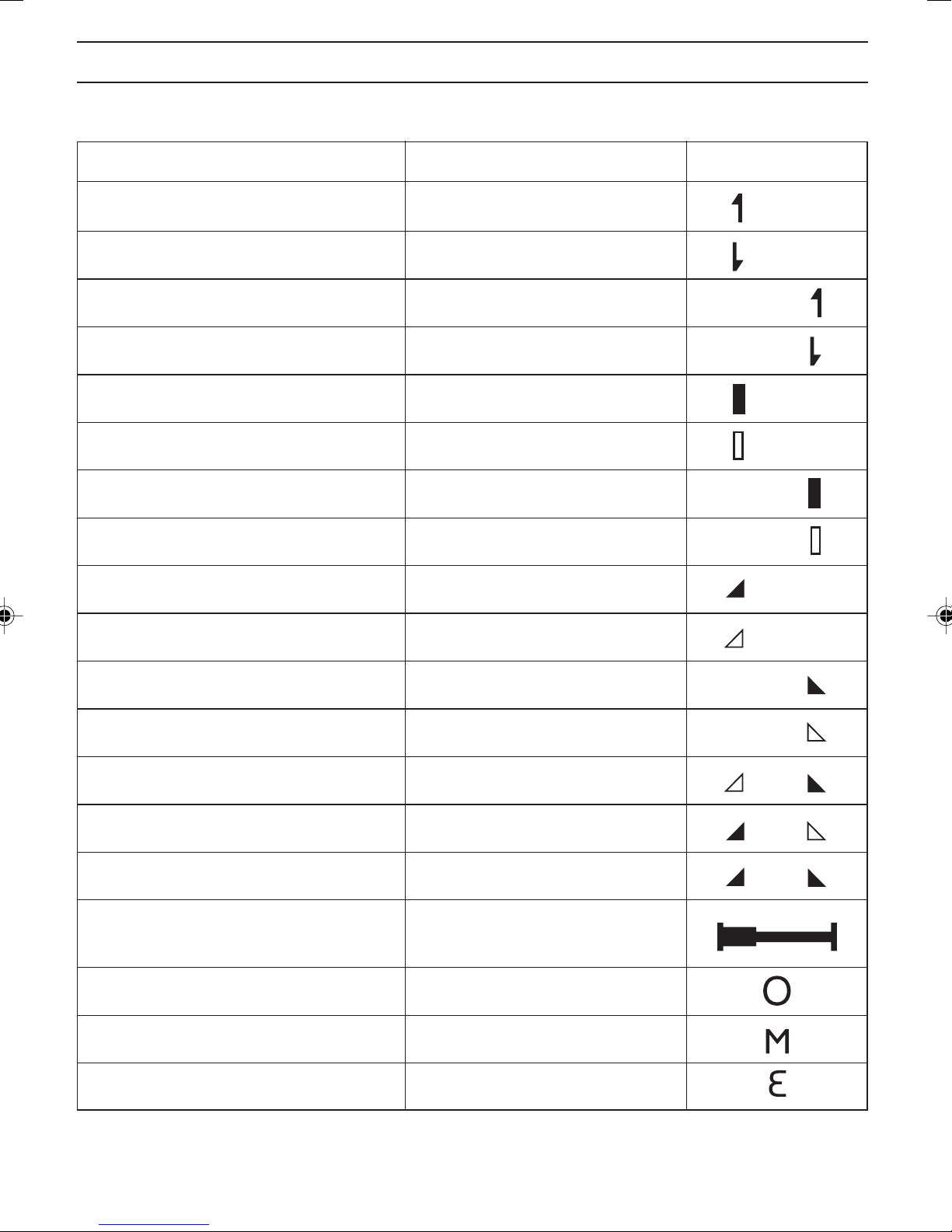
5 Display Symbols
The display of the DULCOMETER
®
D1C controller uses the following symbols:
Description Comment Symbol
Limit value transgression Symbol
Relay 1 upper left
Relay 1 lower left
Relay 2 upper right
Relay 2 lower right
Metering pump 1 (Increase conductivity) Symbol
Control off left
Control on left
Metering pump 2 (Reduce conductivity) Symbol
Control off right
Control on right
Symbol
Symbol
Symbol
Symbol
Symbol
Solenoid valve 1 (Increase conductivity) Symbol
Control off left
Symbol
Control on left
Solenoid valve 2 (Reduce conductivity) Symbol
Control off right
Symbol
Control on right
Servomotor
Control, open relay
Control, close relay
Without control
Thickness of bar
Position feedback increases from left to right
during opening.
Stop button pressed
Manual metering
Fault
6
Page 7
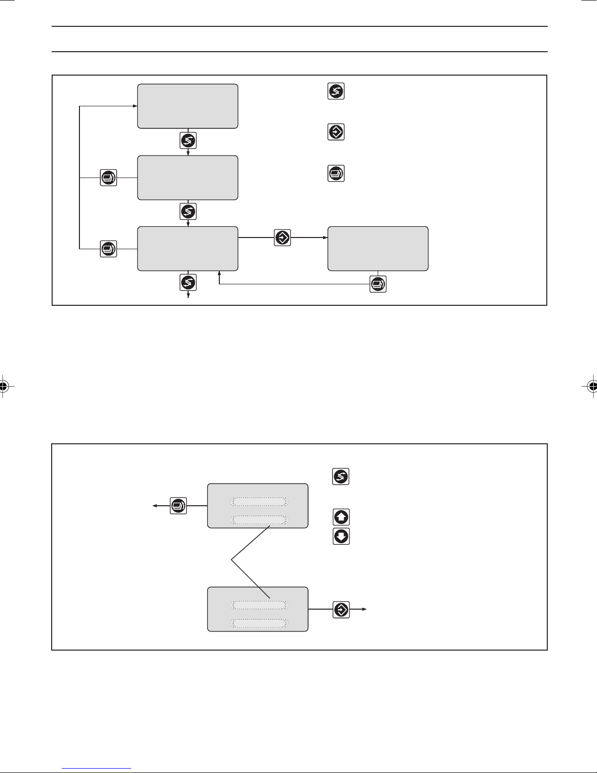
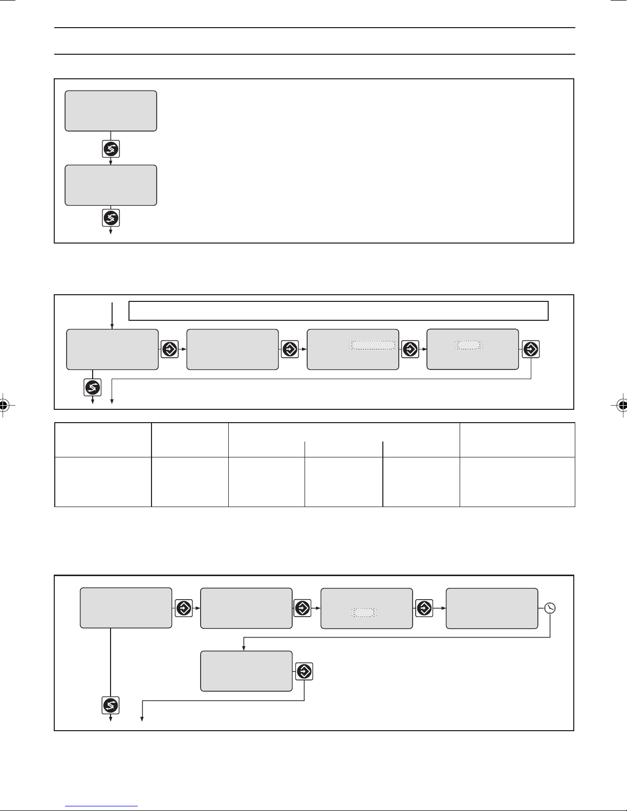
6 Operation diagram
Permanent
display 1
The various menus are selected with
the CHANGE button
The menu is started with
the ENTER button
Permanent
display 2
Various
Setting menus
Access code
NOTE
Access to the setting menus can be barred with the access code!
The number and scope of setting menus depends on the device version!
BRANCH BACK to permanent display
or to relevant setting menu
Access code, correct
Parameter
setting
D1C2-cond.-007-GB
If the access code is selected correctly in a setting menu, the following setting menus are also
accessible!
If within a period of 10 minutes no button is pushed, the unit automatically branches back from
the calibrating menu or a setting menu to the permanent display 1!
BRANCH BACK without
saving setting
BRANCH BACK to
start of setting
Text 1
Selection 1
Text 2
Selection 2
CHANGE from selection to selection
Change numbers or
settings of selection
Variables flash
Text 1
Selection 1
Text 2
Selection 2
ENTER and save setting,
continue to next menu
D1C2-cond.-008-GB
7
Page 8
7 Restricted Operating Menu / General Layout
The restricted operating menu permits simple operation of the most important parameters. The following
overview shows the settings which can be selected:
µS/cm
100
mea val.
fd. fwd.
reg. val.
w:
meas. parameter
setting ?
calibration cc ?
parameter record
setting ?
100 µS/cm
70 %
59 %
1000 µS/cm
PAR1
Only with parameter record 2
PAR1
Permanent display 1
Permanent display 2
only with control
(w = setpoint)
mr = meas. range
cc = cell constant
calibration cc
probe in buffer!
accept value?
1538 µS/cm 8.54
calibration cc
cc: 8.50 /cm
parameter record
Grenzwert2 oben
5.00 ppm
Grenzwert1 unten
1.00 ppm
PS1
Positive values of setting variable:
Negative values of setting variable:
2000 µS/cm
mr :
cc :
1106 µS/cm 25,0 °C
calibration cc
cc: 8.54 /cm
cond: 100 µS/cm
8.54/cm
mr 2 : 2000 µS/cm
cc 2 : 8.54 /cm
1106 µS/cm 25,0 °C
please wait!
Increase conductivity
Reduce conductivity
Number and scope of
setting menus depends
on the device.
Access to setting menus
can be blocked with
access code.
limit PS1
setting ?
Only with control
control
settings ?
Setting in
complete
operating
menu
general setting
information
limit2 upper
Grenzwert2 oben
1500 µS/cm
5.00 ppm
limit1 lower
Grenzwert1 unten
1000 µS/cm
1.00 ppm
control
regulated value:
positive cond
negative cond
control
normal
current regulat.
value:
30 %
or
control
with dead zone
current regulat.
value:
30 %
or
control
manual
current regulat.
value:
ident-code: D1CA
DxL6xxxxxxxxx
software version
D1C-L0 FW-2.03
30 %
➞
➞
For normal control
setpoint
1000 µS/cm
Control with dead zone
setpoint 2 upper
1500 µS/cm
setpoint 1 lower
1000 µS/cm
Proportional control
ctrl. parameter
xp =
10 %
PID control
ctrl. parameter
xp =
10 %
0 s
Ti =
Td =
0 s
Manual control
manual dosing
15 %
regulated range
input HW:
rev. y
input SW:
xx.xx.xx
alarm relais
active
access c.:
operating menu:
english
=
=
restricted
5000
D1C2-cond.-010-GB
8
Page 9
Restricted Operating Menu / Description
µS/cm
Permanent display 1
100
mea val.
fd. fwd.
reg. val.
Conductivity calibration
Measurement parameters
meas. parameter
setting ?
100 µS/cm
70 %
59 %
1000 µS/cmw:
Permanent display 2
only with control
(w = setpoint)
Access to all setting menus can be blocked with an access code !
mr = meas. range
cc = cell constant
Positive values of setting variable: Increase conductivity
Negative values of setting variable: Reduce conductivity
D1C2-cond.-011-GB
2000 µS/cm
mr :
cc :
1106 µS/cm 25,0 °C
8.54/cm
mr 2 : 2000 µS/cm
cc 2 : 8.54 /cm
1106
µS/cm 25,0 °C
D1C2-cond.-030-GB
Possible values
Initial value Increment Lower value Upper value Remarks
Cell constant cc depending on 0.0001/cm 0.0060/cm 0.1499/cm cc can be adjusted for
sensor type 0.001/cm 0.150/cm 1.499/cm all mr over the
used 0.01/cm 1.50/cm 12.00/cm complete area
The measured value can be calibrated by changing the cell constant to the actual conductivity value
(arrow keys).
Cell constant calibration (cc)
calibration cc ?
PAR1
calibration cc
probe in buffer!
accept value?
1538 µS/cm 8.54
calibration cc
cc: 8.50 /cm
calibration cc
cc: 8.54 /cm
cond: 100 µS/cm
please wait!
D1C2-cond.-040-GB
9
Page 10

Restricted Operating Menu / Description
To determine the precise cell constant (cc) of the sensor, place the sensor in a calibration solution (sample 1)
with a known conductivity and select the second menu option. The DULCOMETER® D1C displays the
conductivity it has calculated with the updated parameters. Press Enter when the value is constant.
Select the next menu option and enter the conductivity of the calibration solution (arrow keys). Press Enter.
The D1C displays the recalculated cell constant and saves the value.
The setting menu is inactive when “PAR2“ appears.
During the calibration, the metering is reduced to the set basic load and control stops.
The limit value monitor and the fault diagnosis system are reset. The standard signal of the “measured value“
output is frozen.
Possible values
Initial value Increment Lower value Upper value Remarks
Conductivity Measured value 0.1 µS/cm 0 µS/cm 200 µS/cm Measuring range 200 µS/cm
Calibration 1 µS/cm 0 µS/cm 2000 µS/cm Measuring range 2000 µS/cm
solution (LF) 0.01 mS/cm 0 µS/cm 20 mS/cm Measuring range 20 mS/cm
0.1 mS/cm 0 µS/cm 200 mS/cm Measuring range 200 mS/cm
1 mS/cm 0 µS/cm 2000 mS/cm Measuring range 2000 µS/cm
Parameter record
Only with parameter record 2
parameter record
parameter record
setting ?
PAR1
Grenzwert2 oben
5.00 ppm
Grenzwert1 unten
1.00 ppm
PS1
D1C2-cond.-042-GB
Possible values
Initial value Increment Lower value Upper value Remarks
Parameter record PS1 PS1
PS2
This setting menu can be used to temporarily enable additional parameters of the second parameter record
PAR2 to be edited (in addition to the parameters from the setting menu “measurement parameter setting?“).
I.e. the “limit setting?“ and “mA output 1 (2) setting?“ setting menus are enabled to allow editing of PAR2
(designation PS2) until you exit the series of setting menus from “parameter record“ to “general setting“.
It is possible to switch between the parameter records for operation using the “feed forward control“ contact
input, e.g. during a flushing process (contact open = PAR1, contact closed = PAR2). When switching between
the parameter records, the current parameter record in the setting menu “measurement parameter
setting?”, “limit setting?“ and “mA output 1 (2) setting“ is replaced by the other parameter record
(designation PS1 or PS2).
There is no access to the calibration menus in the case of PAR2 (designation PS2).
NOTE
• The designation PAR1 indicates that the parameter record 1 is actively measuring (contact
input “feed forward control“ e.g. open).
The designation PS1 indicates that the parameter record 1 can be edited.
Exception: The parameter record 1 cannot be edited while it is actively measuring
(designation PAR1). If your controller switches the D1C to parameter set 1 while it is being
edited, the D1C returns to the permanent display.
• PAR2, no control, no standard signal outputs.
10
Page 11

Restricted Operating Menu / Description
Limit values
Access to all setting menus can be blocked with an access code !
Grenzwert2 oben
limit PS1
setting ?
Type of limit Limit 1: lower lower Limit transgression when
transgression Limit 2: upper upper exceeding or dropping
Limit value Limit 1: 100 µS/cm 0.1 µS/cm -10 µS/cm 210 µS/cm Measuring range 200 µS/cm
Limit 2: 150 mS/cm
Limit 1: 1000 µS/cm 1 µS/cm -100 µS/cm 2100 µS/cm Measuring range 2000 µS/cm
Limit 2: 1500 µS/cm
Limit 1: 10 mS/cm 0.01 mS/cm -1 mS/cm 21 mS/cm Measuring range 20 mS/cm
Limit 2: 15 mS/cm
Limit 1: 100 mS/cm 0.1 mS/cm -10 mS/cm 210 mS/cm Measuring range 200 mS/cm
Limit 2: 150 mS/cm
Limit 1: 1000 mS/cm 1 mS/cm -100 mS/cm 2100 mS/cm Measuring range 2000 mS/cm
Limit 2: 1500 mS/cm
limit2 upper
5.00 ppm
1500 µS/cm
Grenzwert1 unten
limit1 lower
1.00 ppm
1000 µS/cm
D1C2-cond.-014-GB
Possible values
Initial value Increment Lower value Upper value Remarks
off* below value
*only with limit value relay
Control
control
settings ?
Access to all setting menus can be blocked with an access code !
Note: The controlled variable is recalculated every second. Only
suitable for processes with time constants greater than 30 s !
Only with control
Setting in
complete
operating
menu
control
regulated value:
positive cond
negative cond
control
normal
current regulat.
value:
30 %
or
control
with dead zone
current regulat.
value:
30 %
or
control
manual
current regulat.
value:
30 %
➞
➞
Positive values of setting variable: Increase conductivity
Negative values of setting variable: Reduce conductivity
For normal control
setpoint
1000 µS/cm
Control with dead zone
setpoint 2 upper
1500 µS/cm
setpoint 1 lower
1000 µS/cm
Proportional control
ctrl. parameter
xp =
PID control
ctrl. parameter
xp =
10 %
Ti =
Td =
0 s
0 s
Manual control
manual dosing
15 %
regulated range
10 %
D1C2-cond.-015-GB
11
Page 12

Restricted Operating Menu / Description
Possible values
Initial value Increment Lower value Upper value Remarks
Setpoint 100 µS/cm 0,1 µS/cm -10 µS/cm 210 µS/cm Measuring range 200 µS/cm
1000 µS/cm 1 µS/cm -100 µS/cm 2100 µS/cm Measuring range 2000 µS/cm
10 mS/cm 0,01 mS/cm -1 mS/cm 21 mS/cm Measuring range 20 mS/cm
100 mS/cm 0,1 mS/cm -10 mS/cm 210 mS/cm Measuring range 200 mS/cm
1000 mS/cm 1 mS/cm -100 mS/cm 2100 mS/cm Measuring range 2000 mS/cm
Control with dead zone
2 setpoints necessary
Setpoint 2 ≥ Setpoint 1
Adjustment of measuring
range on page 9/14
Control parameter xp 10 % 1 % 1 % 500 % xp referred to measuring range
Control parameter Ti off 1 s 1 s 9999 s Function off = 0 s
Control parameter Td off 1 s 1 s 2500 s Function off = 0 s
Manual metering 0 % 1 % -100 % +100 %
Abbreviations for control variables:
xp: 100 %/Kp (inverse proportional coefficient)
: Integration time of I-controller (s)
T
i
Td: Differential time of D-controller (s)
General settings
Access to all setting menus can be blocked with an access code !
general setting
information
ident-code: D1CA
DxL6xxxxxxxxx
software version
D1C-L0 FW-2.03
Possible values
Initial value Increment Lower value Upper value Remarks
Alarm relay active active
not active
Access code 5000 1 1 9999
Language as per as per
identity code identity code
Operating menu restricted restricted
complete
input HW:
rev. y
input SW:
xx.xx.xx
alarm relay
active
access c.:
operating menu:
english
=
=
restricted
5000
D1C2-cond.-016-GB
12
Page 13

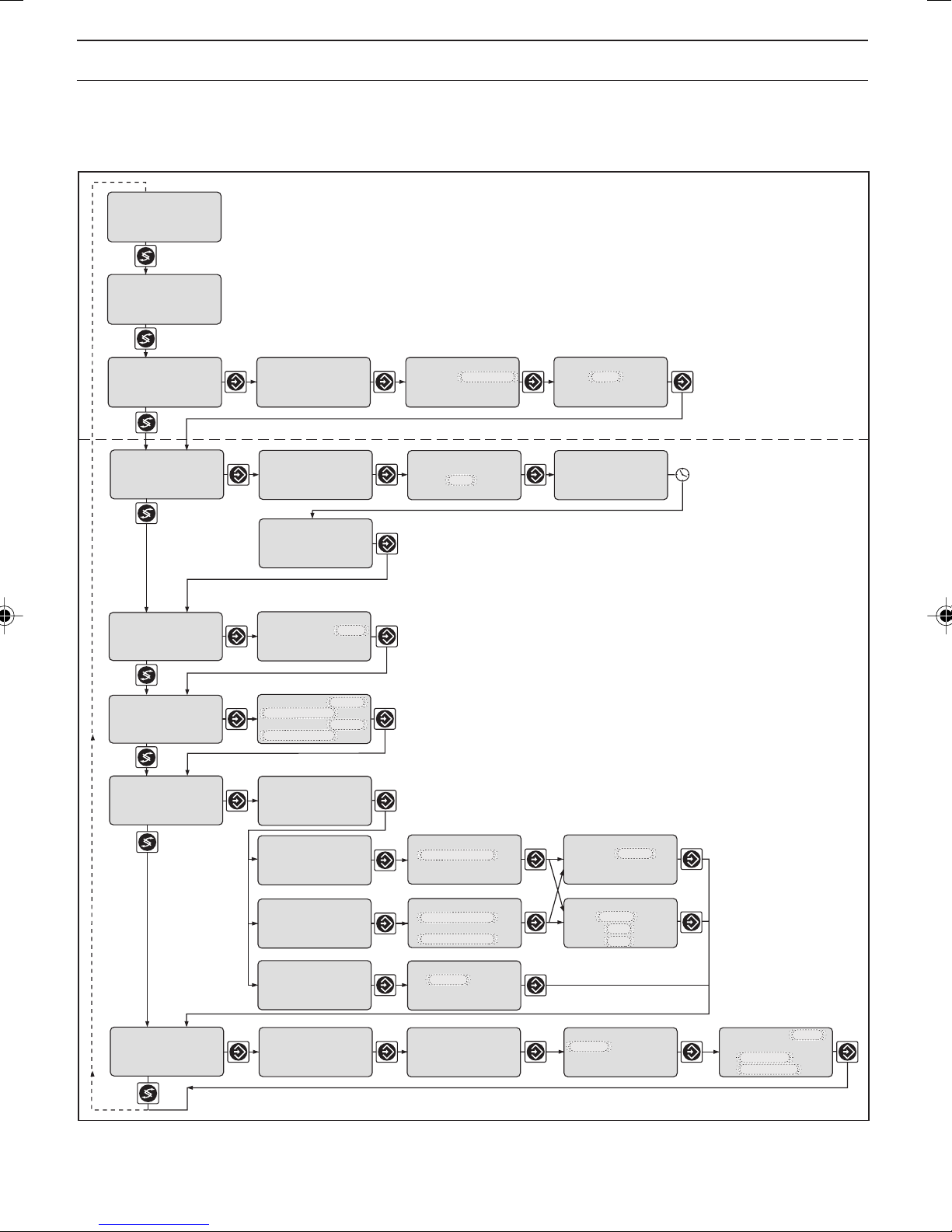
8 Complete Operating Menu / Overview
All parameters of the controller can be set in the complete operating menu (see previous page). The
following overview shows the settings which can be selected:
µS/cm
Permanent display 1
100
mea. val.:
fd. fwd.:
reg. val.:
w: 1000 µS/cm
meas. parameter
setting ?
cali. zero point ?
calibration cc ?
calibration α
cc :
α :
install. factor
setting ?
100 µS/cm
70 %
-59 %
PAR1
PAR1
8,54/cm
1,90 %/°C
PAR1
Permanent display 2
only with control
(w = setpoint)
Number and scope of setting menus
depends on the device.
Access to setting menus can
be blocked with access code.
limits PS1
setting ?
servomotor
setting ?
Only with
servomotor
type of sensor
setting ?
correction value
setting ?
pumps
setting ?
relays
setting ?
parameter record
setting ?
PAR1
Only with correction
variable
Only with pumps
Only with limit value
relay, solenoid valve
relay or servomotor
control
setting ?
feed forward ctrl.
setting ?
mA output 1 PS1
setting ?
mA output 2 PS1
setting ?
general setting
information
Only with control
Only with feed
forward control
Only with standard
signal output
Only with 2 standard signal outputs
D1C2-cond.-017-GB
13
Page 14

Complete Operating Menu / Description
µS/cm
100
mea. val.
fd. fwd.
reg. val.
Measuring parameter
100 µS/cm
70 %
59 %
1000 µS/cmw:
Access to all setting menus can be blocked with an access code !
meas. parameter
setting ?
Permanent display 1
Permanent display 2
only with control
(w = setpoint)
mr: meas. range
cc: cell constant
α: temperature-
coefficient
Positive values of setting variable: Increase conductivity
Negative values of setting variable: Reduce conductivity
D1C2-cond.-018-GB
mr :
cc :
α :
15 mS/cm 23,8 °C
20 mS/cm
8,54/cm
1,90%/°C
mr (2) : 200 µS/cm
cc (2) : 1,120 /cm
α : 1,90%/°C
1106 µS/cm 25,0 °C
D1C2-cond.-036-GB
Possible values
Initial value Increment Lower value Upper value Remarks
Measuring ranges mr 0....2000 µS/cm 0....200 µS/cm At mr 2: 0 = off
0....2000 µS/cm (parameter record
0....20 mS/cm switching)
0....200 mS/cm Setpoint- and limit
0....2000 mS/cm values are switched
to the associated
initial values
Cell constant cc depending on 0.0001/cm 0.0060/cm 0.1499/cm cc can be adjusted
the sensor type 0.001/cm 0.150/cm 1.499/cm for all mr over the
used 0.01/cm 1.50/cm 12.00/cm complete area
Temperature coefficient α 1.90 %/°C 0.01 %/°C0 %/°C 10 %/°C
The measured value can be compensated for by changing the cell constant to the actual conductivity value
(arrow keys!). The precondition is a known temperature coefficient and constant temperature.
Metering and control stops if the measurement range is changed.
Setpoints, limit values and standard signal outputs are switched to the associated starting values. Check
the settings in all menus.
The parameter sets are described on page 21.
14
Page 15

Complete Operating Menu / Description
Calibration of zero point (zp)
cali. zero point ?
PAR1
cali. zero point
probe in air!
accept value?
12 µS/cm
please wait!
D1C2-cond.-039-GB
To determine the precise zero point (zp) of the sensor, hold the sensor in the air and select the second
menu option. The DULCOMETER® D1C displays the conductivity without zero point correction. Press
Enter when the value is constant.
The setting menu is inactive when “PAR2“ appears.
During the calibration, the metering is reduced to the set basic load and control stops. The limit value
monitor and the fault diagnosis system are reset. The standard signal of the “measured value“ output is
frozen.
Cell constant calibration (cc)
calibration cc ?
PAR1
calibration cc
probe in buffer!
accept value?
1538 µS/cm 8.54
calibration cc
cc: 8.50 /cm
calibration cc
cc: 8.54 /cm
LF: 100 µS/cm
please wait!
D1C2-cond.-043-GB
To determine the precise cell constant (cc) of the sensor, place the sensor in a calibration solution
(sample 1) with a known conductivity and select the second menu option. The DULCOMETER® D1C
displays the conductivity which it has calculated with the current parameters. Press Enter when the value
is constant.
Select the next menu option and enter the conductivity of the calibration solution (arrow keys). Press Enter.
The D1C displays the recalculated cell constant and saves the value.
The setting menu is inactive when “PAR2“ appears.
During the calibration, the metering is reduced to the set basic load and control stops. The limit value
monitor and the fault diagnosis system are reset. The standard signal of the “measured value“ output is
frozen.
Possible values
Initial value Increment Lower value Upper value Remarks
Conductivity Measured value 0.1 µS/cm 0 µS/cm 200 µS/cm Measuring range 200 µS/cm
Calibration 1 µS/cm 0 µS/cm 2000 µS/cm Measuring range 2000 µS/cm
solution (LF) 0.01 mS/cm 0 µS/cm 20 mS/cm Measuring range 20 mS/cm
0.1 mS/cm 0 µS/cm 200 mS/cm Measuring range 200 mS/cm
1 mS/cm 0 µS/cm 2000 mS/cm Measuring range 2000 µS/cm
15
Page 16

Complete Operating Menu / Description
Calibration of temperature coefficient α
The temperature coefficient α is determined again by means of a two point calibration. During the
calibration, the metering is reduced to the set basic load and control stops. The limit value monitor and the
fault diagnosis system are reset. The standard signal of the measured value or correction value output is
reduced to 0/4 mA.
IMPORTANT
Only values determined at 25 °C may be entered as conductivity values. The calibration
must be carried out with the same solution at both temperatures.
Access to all setting menus can be blocked with an access code !
calibration α
cc :
α :
8,54/cm
1,90 %/°C
PAR1
calibration at
temperature 1
probe in buffer !
1538 23,8 °C
calibration at
temperature 2
probe in buffer !
1500 48,5 °C
calibration α
cc :
α :
8,50/cm
2,52 %/°C
calibration at
temperature 1
accept value ?
1538 23,8 °C
calibration at
temperature 2
accept value ?
1500 48,5 °C
calibration
value:
temp1
calibration
value:
temp1
temp2
23,8 °C
23,8 °C
48,5 °C
permanent display 1
Possible values
Initial value Increment Lower value Upper value Remarks
Set temperature Correction value 0.1 °C0 °C 100 °C
Error message/Warning Condition Remarks
Temperature range restricted For the chosen temperature
xx – 100 °C coefficient α, a correct reading
can only be obtained for the
displayed temperature range
1500
1500
D1C2-cond.-032-GB
Temperature interval incorrect ∆ temperature ≥ 10.0 °C
16
∆ temperature ≤ 50.0 °C
Page 17

Complete Operating Menu / Description
Installation factor setting
install. factor
setting ?
install. factor
1.00
100 µS/cm
D1C2-cond.-041-GB
Possible values
Initial value Increment Lower value Upper value Remarks
Installation factor 1.00 0.01 0.01 9.99
Enter the installation factor of the installed sensor here (arrow keys!). Determine the installation factor using
the data from the sensor documentation and the installation geometry.
Type of sensor setting
type of sensor
setting ?
type of sensor :
ICT 1
sensor data
are changed!
D1C2-cond.-044-GB
Possible values
Initial value Increment Lower value Upper value Remarks
Type of sensor ICT 1 ICT 1 The default
ICT 1-IMA actuation parameters
ICT 2 / CLS50 are loaded
ICT 3 / CLS52
When changing the sensor, press Enter to load the actuation parameters permanently stored in
®
DULCOMETER
D1C for this sensor type. Metering and control stop and the measured value-specific error
messages are deleted.
IMPORTANT
• The limit values, the setpoints and the standard signal outputs are set to the default
values.
• Check the settings in all menus!
17
Page 18

Complete Operating Menu / Description
Correction value
Access to all setting menus can be blocked with an access code !
only with correction variable
correction value
setting ?
Type of temperature as per manual
compensation identity code automatic
Manual temperature 25 °C 0.1 °C -199.9 °C 199,9 °C
correction value
calibration temp.
automatic
33,0 °C
Possible values
Initial avalue Increment Lower value Upper value Remarks
off
D1C2-cond.-034-GB
Automatic temperature Correction value 0.1 °C -5.0 °C 5,0 °C by the temperature
measured value
Pumps
Access to all setting menus can be blocked with an access code !
only with pumps for control
pump
setting ?
control
pump 1 cond
pump 2 cond
➞
➞
Possible values
Initial value Increment Lower value Upper value Remarks
Max. stroke/minute of 180 1 1 500 off = 0 strokes/min
pumps 1 and 2
dosing pump max.
pump 1:
pump 2:
180
180
pulse/minute
D1C2-cond.-022-GB
18
Page 19

Complete Operating Menu / Description
Relay for power control
Access to all setting menus can be blocked with an access code !
only with limit value relay, solenoid valve relay or servomotor
relay
setting ?
relay adjustment
relay1:
relay2:
SV1
SV2
control cond.
solenoid valves
SV1 cond
SV2 cond
➞
➞
solenoid value 1
cond
➞
period
min. time
10 s
1 s
solenoid value 2
➞
cond
period
min. time
10 s
1 s
D1C2-cond.-023-GB
Possible values
Initial value Increment Lower value Upper value Remarks
Relay adjustment as per Motor *At "limit value" the
identity code Solenoid valve (SV1, SV2) relays remain active
Limit value (Limit 1/2) even with a fault.
Actuator 1,2
Servomotor
off
Cycle 10 s 1 s 10 s 9999 s for solenoid valve
min. time 1 s 1 s 1 s cycle/2 for solenoid valve
NOTE
The limit value relays can also be defined such that they react like an actuator. If e.g. a limit value
relay picked up, it will drop at a closed pause contact or for a subsequent delay time t
(if td > 0 min
d
is set in “General settings”).
19
Page 20

Complete Operating Menu / Description
Cycle
Solenoid
valve
on
off
on
off
The switching time of the DULCOMETER® D1C (solenoid valve) depends on the actuating variable and the
“min. time“ (smallest permitted operating factor of the connected device).
The actuating variable determines the ratio ton/cycle and thus the switching times (see fig. above).
The “min. time“ influences the switching times in two situations:
a) theoretical switching time < min. time:
Cycle
min. time
on
off
Cycle
on
off
t
on
t
on
Cycle
Cycle
Cycle
Cycle
Cycle
min. time
min. time
Actuating
variable: 80 %
t
on
Cycle
t
Actuating
variable: 50 %
t
on
Cycle
t
theoretical
t
actual
t
= 0.80
= 0.50
The DULCOMETER® D1C does not switch for a certain number of cycles until the sum of the theoretical
switching times exceeds the “min. time“. Then the DULCOMETER® D1C switches for the duration of this
total time.
b) theoretical switching time > (cycle - min. time) and calculated switching time < cycle
Cycle
min. time
on
off
Cycle
on
off
Cycle
Cycle
Cycle
Cycle
min. time
theoretical
t
actual
t
The DULCOMETER® D1C does not deactivate for a certain number of cycles until the differences between
cycle and theoretical switching time exceed the "min. time".
20
Page 21

Complete Operating Menu / Description
Parameter record
only with parameter record 2
parameter record
parameter record
setting ?
PAR1
Parameter record PS1 PS1
This setting menu can be used to temporarily enable additional parameters of the second parameter record
PAR2 to be edited (in addition to the parameters from the setting menu “measurement parameter
setting?“). I.e. the “limit value setting“ and “mA output 1 (2) setting?“ setting menus are enabled to allow
editing of PAR2 (designation PS2!) until you exit the series of setting menus from “parameter record“ to
“general setting“.
It is possible to switch between the parameter records for operation using the “feed forward control“
contact input, e.g. during a flushing process (contact open = PAR1, contact closed = PAR2). When
switching between the parameter records, the current parameter record in the setting menus “meas.
parameter setting?”, “limit setting?“ and “mA output 1 (2) setting“ is replaced by the other parameter
record (designation PS1 or PS2).
There is no access to the calibration menus in the case of PAS2 (designation PS2!).
Grenzwert2 oben
5.00 ppm
Grenzwert1 unten
1.00 ppm
PS1
D1C2-cond.-045-GB
Possible values
Initial value Increment Lower value Upper value Remarks
PS2
NOTE
• The designation PAR1 indicates that the parameter record 1 is actively measuring (contact
input “feed forward control“ e.g. open).
The designation PS1 indicates that the parameter record 1 can be edited.
Exception: The parameter record 1 cannot be edited while it is actively measuring (designation
PAR1). If your controller switches the D1C to parameter record 1 while it is being edited, the
D1C returns to the permanent display.
• PAR2, no control, no standard signal outputs.
21
Page 22

Complete Operating Menu / Description
Limit values
Access to all setting menus can be blocked with an access code !
limit 1
1000 µS/cm
limits PS1
setting ?
lower
limit 2
1500 µS/cm
upper
Only with limit value relay
0 s
0 s
lower
limit 2
1500 µS/cm
∆t on
∆t off
limit 1
time:
limit 2
time:
0 s
0 s
0 s
0 s
upper
max.
max.
hysteresis
limits:
checkout time
limits:
10 µS/cm
off
D1C2-cond.-024-GB
limit 1
1000 µS/cm
∆t on
∆t off
Possible values
Initial value Increment Lower value Upper value Remarks
Type of limit Limit 1 lower upper Limit transgression when
transgression Limit 2 upper lower exceeding or dropping
off* below value.
*only with limit value relay
Limit value1; Limit value 2 0; 2000 mS/cm 1 mS/cm -100 mS/cm 2100 mS/cm Meas. range 2000 mS/cm
0; 200 mS/cm 0.1 mS/cm -10 mS/cm 210 mS/cm Meas. range 200 ms/cm
0; 20 mS/cm 0.01 mS/cm -1 mS/cm 21 mS/cm Meas. range 20 ms/cm
0; 2000 µS/cm 1 µS/cm -100 µS/cm 2100 µS/cm Meas. range 2000 µs/cm
0; 200 µS/cm 0.1 µS/cm -10 µS/cm 210 µS/cm Meas. range 200 µs/cm
Hysteresis limit values 10 mS/cm 1 mS/cm 0 mS/cm 2100 mS/cm Effective in direction of
1 mS/cm 0.1 mS/cm 0 mS/cm 210 mS/cm ” Cancelling limit trans-
0.1 mS/cm 0.01 mS/cm 0 mS/cm 21 mS/cm gression”
10 µS/cm 1 µS/cm 0 µS/cm 2100 µS/cm
1.0 µS/cm 0.1 µS/cm 0 µS/cm 210 µS/cm
Checkout time limits t on off 1 s 1 s/off 9999 s Results in message and
alarm.
off = 0 s:
Function switched off,
no message, no alarm
Switch-on delay 0 s 1 s 0 s 9999 s Only available in
∆ t on complete operating menu
Switch-off delay 0 s 1 s 0 s 9999 s Only available in
∆ t off complete operating menu
Max. switch-on time off 1 s 0 s/off 9999 s Only available in
Limit value 1; complete operating menu
Limit value 2 Function switched off
If the limit transgression is longer than the “delay time limit value“, an error message is triggered (requires
acknowledgement) and the alarm relay opens; if “control“ is also set to “off“, the control process will stop.
22
Page 23

Complete Operating Menu / Description
Servomotor
The operating range is given by the overall resistance range of the feedback potentiometer. Defining the
control range places a maximum limit on the control range used.
IMPORTANT
• The servomotor must be actuated with the same care as for the calibration of a measuring
sensor.
• To ensure correct function, the control duration of the servomotor must be at least
25 seconds for 0...100 % of the control range.
Access to all setting menus can be blocked with an access code !
only with servomotor
servomotor
setting ?
servomotor
setting
current position:
servomotor
open
servomotor
open
please wait !
servomotor
opened !
Value take over ?
servomotor
OK
current position:
Possible values
Initial value Increment Lower value Upper value Remarks
Servomotor Setting Setting
ok
off
Control direction Cond. Cond.
Cond.
servomotor
close ?
dosing
control range:
0 % to
operating range
cond
100 %
servomotor
closed
please wait !
servomotor
closed !
value take over ?
➞
= automatic timing
D1C2-cond.-025-GB
Control range 100 % 1 % 10 % 100 % in % of
NOTE
• When the wide bar is as far right as it will go, the servomotor is fully open.
• The permanent display shows to what degree the motor has opened in % (the greater the
percentage, the farther open the servomotor).
operating range
23
Page 24

Complete Operating Menu / Description
Control
Access to all setting menus can be blocked with an access code !
Note: The controlled variable is recalculated every second. Only
suitable for process with time constants greater than 30 s !
control
settings ?
Only with control
control
regulated value:
positive cond
negative cond
control
normal
current regulat.
value:
30 %
➞
➞
Positive values of setting variable:
Negative values of setting variable:
For normal control
setpoint
1000 µS/cm
Control with dead zone
setpoint 2 upper
1500 µS/cm
setpoint 1 lower
1000 µS/cm
Control manual
manual dosing
15 %
regulated range
Increase conductivity
Reduce conductivity
Proportional control
ctrl. parameter
xp =
PID control
ctrl. parameter
xp =
10 %
Ti =
Td =
additional load:
10 %
regulated range
Possible values
Initial value Increment Lower value Upper value Remarks
10 %
10 s
0 s
D1C2-cond.-026-GB
Control normal normal When controlling with dead
with dead zone zone, the regulated value is
manual not used for measured values
within the dead zone
Setpoint setting 1000 mS/cm 1 mS/cm -100 mS/cm 2100 mS/cm Measuring range 2000 mS/cm*
100 mS/cm 0.1 mS/cm -10 mS/cm 210 mS/cm Measuring range 200 mS/cm
10 mS/cm 0.01 mS/cm -1 mS/cm 21 mS/cm Measuring range 20 mS/cm
1000 µS/cm 1 µS/cm -100 µS/cm 2100 µS/cm Measuring range 2000 µS/cm
100 µS/cm 0.1 µS/cm -10 µS/cm 210 µS/cm Measuring range 200 µS/cm
Setpoint 2 ≥ setpoint 1
Control parameter xp 10 % 1 % 1 % 500 % xp referred to measuring range
Control parameter Ti off 1 s 1 s 9999 s Function off = 0 s
Control parameter Td off 1 s 1 s 2500 s Function off = 0 s
Additional basic load 0 % 1 % -100 % +100 %
Manual metering 0 % 1 % -100 % +100 %
Abbreviations for control variables:
xp: 100 %/Kp (inverse proportional coefficient)
: Integration time of I-controller (s)
T
i
Td: Differential time of D-controller (s)
24
Page 25

Complete Operating Menu / Description
Feed forward control
feed forward ctrl.
setting ?
feed forward ctrl.
Hz / mA
10 Hz
feed forward ctrl.:
rated value:
10.00 Hz
feed forward ctrl.
effect:
additive
feed forward ctrl.
max. additive
regulated value
100 %
D1C2-cond.-035-GB
Possible values
Initial value Increment Lower value Upper value Remarks
Feed forward control as per none Signal processing:
(flow) identity code at 10 Hz Signal < 0,2 mA = No flow
standard signal 500 Hz Signal < 4,2 mA = No flow
0...20 mA
4...20 mA
Feed forward control 20 mA 0.01 mA 0/4 mA 20 mA Depending on signal type.
rated value 10 Hz 0.01 Hz 0.1 Hz 10 Hz Maximum limitation of
500 Hz 1 Hz 5 Hz 500 Hz range used.
Feed forward control multiplicative multiplicative
Feed forward effect additive
Max. additive regulated 100 % 1 % -500 % +500 % Only with additive
value regulated value.
Standard signal output 1
Access to all setting menus can be blocked with an access code !
only with standard signal output
mA output 1 PS1
setting ?
mA output 1
measured value
0…20 mA
Control with standard signal
control
regulated value:
positive cond
negative cond
mA output 1
measured value
0 mA =
20 mA =
mA output 1
correction value
0 mA =
20 mA =
➞
➞
0,0 mS/cm
200.0 mS/cm
0.0 °C
100.0 °C
mA output 1
regulated value
0 mA =
20 mA =
0%
100%
D1C2-cond.-027-GB
25
Page 26

Complete Operating Menu / Description
Standard signal output 2
Access to all setting menus can be blocked with an access code !
Access to all setting menus can be blocked with an access code !
Control with standard signal
control
Only with 2 standard signal outputs
mA output 2 PS1
setting ?
mA output 2
measured value
0…20 mA
Possible values
Initial value Increment Lower value Upper value Remarks
regulated value:
positive cond
negative cond
mA output 2
measured value
0 mA =
20 mA =
mA output 2
correction value
0 mA =
20 mA =
➞
➞
0 mS/cm
200.0 mS/cm
0.0 °C
100.0 °C
mA output 2
regulated value
0 mA =
20 mA =
0%
100%
D1C2-cond.-037-GB
Variable allocation as per identity Measured value
code Controlled variable If control is present
Correction value
off
Output range 0…20 mA 0…20 mA No setting in case of PAR2
4…20 mA
3.6/4-20 mA Reduction to 3.6 mA
when alarm relay switches
(not limit value violation)
Range measured 0–200 µS/cm 0.1 µS/cm -10 µS/cm 210 µS/cm at meas. range up to 200 µS/cm
value 0–2000 µS/cm 1 µS/cm -100 µS/cm 2100 µS/cm at meas. range up to 2000 µS/cm
0–20 mS/cm 0.01 mS/cm -1 mS/cm 21 mS/cm at meas. range up to 20 mS/cm
0–200 mS/cm 0.1 mS/cm -10 mS/cm 210 mS/cm at meas. range up to 200 mS/cm
0-2000 mS/cm 1 mS/cm -100 mS/cm 2100 mS/cm at meas. range up to 2000 mScm
Range regulated 0 %…+100 % 1 % -100 % +100 % Minimum range 1 %
value No setting in case of PAR2
Range correction 0…100,0 °C 0,1 °C 0,0 °C 100 °C Minimum range 1 %
variable -199.9 °C +199.9 °C No setting in case of PAR2
General setting
Access to all setting menus can be blocked with an access code !
general setting
information
ident-code: D1CA
DxL6xxxxxxxxx
software version
D1C-L0 FW-2.03
26
input HW:
rev. y
input SW:
xx.xx.xx
control input
– active closed
– parameter set 2
alarm relay
active
acces c.:
operating menu:
=
english
complete
=
5000
pause normal
– active...closed
– alarm off
– td: 0 min
D1C2-cond.-028-GB
Page 27

Complete Operating Menu / Description
Possible values
Initial value Increment Lower value Upper value Remarks
Alarm relay active active
not active
Pause normal normal
hold
Control input pause active closed active closed
active open
Alarm pause Alarm off Alarm off Alarm relay can be
Alarm on activated by pause
contact
Pause 0 min 1 min 0 min 60 min
Time delay td
Input control active closed active closed Switch status for
Input active open parameter record 2
Only with parameter
record switching
Control input Parameter set 2 Parameter set 2 off = parameter set
Function off switching off
Only with parameter
record switching
Access code 5000 1 1 9999
Language as per as per
identity code identity code
Operating menu complete restricted
complete
Normal pause
If the pause switch is off, the DULCOMETER® D1C sets the operating outputs to “0“ for as long as the
pause switch is off or for a set time delay td (if td is set to > 0 min). Whilst the pause switch is off, the
DULCOMETER® D1C establishes the P-proportion in the background.
With PID-control (identity code characteristics “control characteristic“ : 2): the I-porportion is stored when
the pause is switched off (I-porportion then usually only present if Ti > 0 has been selected in the “control
setting?“ setting menu).
Exception: the standard signal outputs mA for the measured value or correction value are not affected by
the pause.
After pause is activated, the operating outputs remain at “0“ for the length of the time delay td. The time
delay td must be set up in such a way that in this time e.g. sample water (process-specific current
concentration) flows to the sensor.
With PID-control (identity code characteristics “control characteristic“: 2): The control variable output
resulting from the pause and the expiry of the time delay td is reconciled jointly with the current
P-component and (if Ti is set > 0) with the stored I-component.
Pause hold
If the pause switch is off, the DULCOMETER
®
D1C freezes the operating output at the most recent value
for as long as the pause switch is off or for a set time delay td (if td is set to > 0 min). Whilst the pause
switch is off, the DULCOMETER® D1C establishes the P-proportion in the background.
With PID-control (Identity code characteristics “control characteristic“ : 2):
Even the mA standard signal outputs for measured value or correction value are frozen.
After pause is activated, the operating outputs remain frozen for the length of the time delay td. The time
delay td must be set up in such a way that, in this time e.g. sample water (process-specific current
concentration) flows to the sensor.
With PID-control (identity code characteristics “control characteristic“: 2): The control variable output
resulting from the pause and the expiry of the time delay td is reconciled jointly with the current
P-proportion and (if Ti is set > 0) with the newly established I-proportion.
27
Page 28

9 Fault / Remarks / Troubleshooting
Calibration
Calibration
with error
During servomotor setting
Position feedback
Upper position <40 % max. value
Lower position >30 % range
Stop button
Check measurement
Final value high
Check direction
Final value low
range
Stop
Basic load Stop ––Repeat calibration
Stop Stop no Relay drops out –
Operating step Note text Symbol Effect
Pause contact
Control input
Parameter set 2
Pause/Hold
Pause
on metering on control
Stop Stop no/yes No further fault check –
Stop Stop no
Electronic error
position not reached
amplifier defective,
LF cable defective,
check SPI
System error
defective
Basic load Stop yes
Stop Stop yes Electronic data defective Call customer service
Limit value violation
Servomotor
after control time
mS-limit 1
mS-limit 2
Servomotor
↑↓
↑↓
Feed forward control
Signal exceeded/drops below value
Signal below value, multiplicative
Check feed forward
input
"
Signal exceeded/drops below value
Upper Te. limit value exceeded
Te. limit value
Check Te. input
↑ Basic load Stop yes at α ≥ 4 %/°C
Basic load Stop yes Signal <3.8 ±0.2 mA Check sensor, transformer
Checkout time exceeded*
Correction measured variable
Check mS probe
Basic load Stop yes Function detachable Check sensor function,
Error Fault text Symbol Effect
Measured value
Signal exceeded/drops below value*
mS measurement
Check mS input
range
↑↓ Basic load Stop yes outside range setting
on metering on control
Basic load Stop yes Measured value Check measured variable
adjustment, the last valid and relay connection
values are still used Set correct servomotor
Without correct Check potentiometer
operating range
solution
Stop no/yes
Check sensor/calibration
Alarm with ack-
nowledgement
Comment Remedy
Stop yes The last valid value
yes closes Check servomotor
yes Function detachable Define cause
Servomotor
is used
Reset values if necessary
yes Signal <3.0 ±0.2 mA Check sensor, transformer
or >23 ±0.2 mA and cable connection
or >23 ±0.2 mA and cable connection
extend control time
Check sensor and cable
connection
Alarm with ack-
nowledgement
Remarks Remedy
©2004 ProMinent Dosiertechnik GmbH · 69123 Heidelberg · Germany
Operating Instructions DULCOMETER
ProMinent Dosiertechnik GmbH · Im Schuhmachergewann 5-11 · 69123 Heidelberg · Germany
28
®
D1C, Part 2 Inductive Conductivity
Subject to modifications · Printed in Germany
Phone: +49 6221 842-0 · Fax: 842-419
info@prominent.com · www.prominent.com
 Loading...