

Page 1
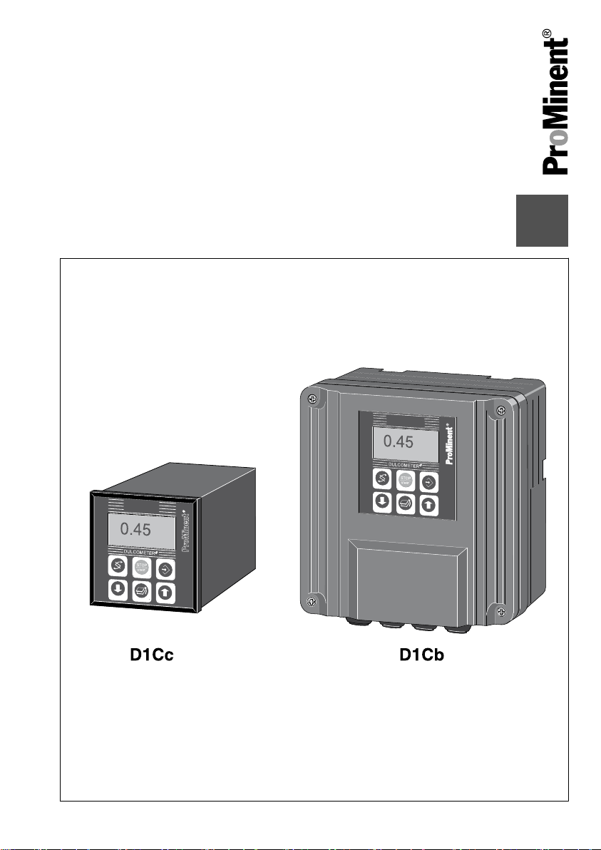
Assembly and operating instructions
DULCOMETER® D1Cb / D1Cc
Please carefully read these operating instructions before use! · Do not discard!
The operator shall be liable for any damage caused by installation or operating errors!
Technical changes reserved.
Teile Nr. 986362 BA DM 187 09/11 EN
Page 2

ProMinent Dosiertechnik GmbH
Im Schuhmachergewann 5 - 11
69123 Heidelberg
Telephone: +49 6221 842-0
Fax: +49 6221 842-419
email: info@prominent.de
Internet: www.prominent.com
986362, 4, en_GB
© 2011
2
Page 3

General non-discriminatory approach
In order to make it easier to read, this
document uses the male form in grammat‐
ical structures but with an implied neutral
sense. It is aimed equally at both men and
women. We kindly ask female readers for
their understanding in this simplification of
the text.
Supplementary information
Read the following supplementary infor‐
mation in its entirety!
The following are highlighted separately in
the document:
n Enumerated lists
Instructions
Results of the instructions
ð
Supplemental instructions
Information
This provides important information
relating to the correct operation of the
system or is intended to make your
work easier.
Safety information
Safety information are provided with
detailed descriptions of the endangering
situation, see
Ä Chapter 1.1 ‘Explanation
of the safety information’ on page 8
3
Page 4

Table of contents
Table of contents
1 Introduction............................................................................................................. 8
1.1 Explanation of the safety information............................................................. 8
1.2 Users' qualifications...................................................................................... 10
1.3 General Safety Information.......................................................................... 11
1.4 Correct and proper use................................................................................ 13
1.5 ID Code........................................................................................................ 14
2 Functional description........................................................................................... 17
2.1 Wall mounting/control panel installation....................................................... 18
2.2 Electrical construction.................................................................................. 19
2.2.1 Block circuit diagram................................................................................. 20
2.2.2 Galvanic Isolation ..................................................................................... 21
3 D1Cb mounting..................................................................................................... 22
3.1 Scope of supply............................................................................................ 23
3.2 Installation (Wall Mounted) .......................................................................... 24
3.3 Installation - Control Panel Mounted (Optional) .......................................... 25
3.4 Wall Mounted Installation of D1Cb (Electrical) ............................................ 27
3.4.1 Opening the device................................................................................... 28
3.4.2 Electrical Installation (Wall Mounted) ....................................................... 29
3.4.3 Electrical Installation (Control Panel Mounted) ........................................ 30
3.4.4 Installation of Coaxial Cable to Guard Terminal XE1 ............................... 31
3.4.5 Cable Cross-Sections and Cable End Sleeves......................................... 32
3.4.6 Protective RC Circuit (Optional) ............................................................... 33
3.4.7 Terminal Wiring Diagram .......................................................................... 34
3.5 Switching of inductive loads......................................................................... 38
4 D1Cc mounting..................................................................................................... 40
4.1
DULCOMETER® D1Cc scope of supply...................................................... 41
4.2
Mounting - control panel installation DULCOMETER®
4.3 Electrical Installation (Control Panel Mounted)............................................ 44
4.3.1 Installation of Coaxial Cable to Guard Terminal XE1................................ 45
4.3.2 Cable Cross-Sections and Cable End Sleeves......................................... 47
4.3.3 Terminal diagram ..................................................................................... 48
4.4 Switching of inductive loads......................................................................... 50
D1Cc....................... 41
4
Page 5

Table of contents
5 Commissioning..................................................................................................... 52
5.1 Initial commissioning ................................................................................... 52
5.1.1 Selection of the Operating Language........................................................ 52
5.1.2 Selection of the Measured Variable and Measuring Range...................... 54
5.2 Activation Code for Extended Functions...................................................... 55
5.2.1 Extended Functions Obtainable with the Activation Code......................... 55
6 Operating diagram/ Display Symbols................................................................... 59
6.1 Overview of equipment/Control elements.................................................... 59
6.2 Display Symbols........................................................................................... 60
6.3 Permanent Display 1 ................................................................................... 61
6.4 Continuous display 2.................................................................................... 62
6.5 Continuous display 3.................................................................................... 62
6.6 Operating diagram........................................................................................ 64
6.7 Reduced / Complete Operating Menu ......................................................... 67
6.8 Fault Messages............................................................................................ 67
6.8.1 Fault display.............................................................................................. 67
6.9 General settings........................................................................................... 68
6.9.1 Access code.............................................................................................. 68
7 Measured Variables and Operating Menus for Amperometric Sensors............... 69
7.1 Reduced / Complete Operating Menu ......................................................... 70
7.2 Description of All Amperometric Measured Variables ................................. 70
7.3 Reduced Operating Menu ........................................................................... 71
7.4 Complete Operating Menu / Description of All Measured Variables............ 73
7.5 Calibration of All Amperometric Measured Variables .................................. 74
7.6 Calibration of the Sensor for Amperometric Measured Variables................ 75
7.6.1 Preparation for Calibration of the Sensors for Amperometric Measured
Variables .................................................................................................. 75
7.6.2 Calibration of Zero Point and Slope.......................................................... 76
7.7 Setting the Measured value.......................................................................... 79
7.8 Correcting value........................................................................................... 79
8 Measured Variables and Operating Menus for Potentiometric Sensors............... 81
8.1 Reduced / Complete Operating Menu ......................................................... 82
8.2 Description of pH, Redox and Fluoride Measured Variables ...................... 82
8.3 Reduced pH / Redox / Fluoride Operating Menu ........................................ 83
8.4 Complete Operating Menu/Description of pH / ORP / Fluoride.................... 85
8.5 Calibration of pH, ORP and Fluoride Sensors.............................................. 87
5
Page 6

Table of contents
8.5.1 Description of the Calibration of pH Sensors ........................................... 88
8.5.2 Calibration of pH Sensors. Description of the Setting Ranges ................. 91
8.5.3 Calibration of pH Sensors. Description of the Error Messages ................ 91
8.5.4 Testing the Redox Sensor ........................................................................ 92
8.5.5 Description of the Calibration of Fluoride Sensors.................................... 95
8.6 Temperature correction value for pH and fluoride sensors.......................... 99
9 Measured Variables and Operating Menus for the Standard Signal General..... 101
9.1 Explanation of the Standard Signal General.............................................. 101
9.2 Changing the Measured Variable .............................................................. 103
9.3 Reduced / Complete Operating Menu ....................................................... 104
9.4 Setting the Reading ................................................................................... 104
9.5 Description of All Standard Signal Measured Values/Measured
Variables ................................................................................................... 105
9.6 Reduced Operating Menu ......................................................................... 106
9.7 Complete Operating Menu / Description of All Measured Variables ......... 108
9.8 Calibrating the Standard Signal ................................................................. 109
9.8.1 Calibration of the Zero Point of the Standard Signal General................. 110
9.8.2 Two-Point Calibration of the Standard Signal General............................ 111
10 Operating Menus Independent of Measured Variables...................................... 113
10.1 Pumps ..................................................................................................... 114
10.2 Setting the Relays.................................................................................... 116
10.2.1 Setting and Functional Description of the Relays.................................. 117
10.3 Setting the Limits...................................................................................... 122
10.4 Setting the Control.................................................................................... 125
10.5 Set mA output........................................................................................... 129
10.6 General settings....................................................................................... 131
10.6.1 Setting the Measured Variable/Measuring Range................................. 131
10.6.2 Sub-Functions of the "General Settings" Menu..................................... 132
11 Maintenance....................................................................................................... 136
11.1
Fuse replacement DULCOMETER®
11.2 Summary of Error Texts .......................................................................... 138
12 Technical data.................................................................................................... 141
12.1
Ambient conditions DULCOMETER® D1Cb / D1Cc ................................ 141
12.2 Sound Pressure Level.............................................................................. 141
12.3 Material Data............................................................................................ 142
D1Cb / D1Cc ................................. 136
6
Page 7

Table of contents
12.4 Chemical Resistance................................................................................ 142
12.5 Dimensions and weights.......................................................................... 143
13 Electrical Data .................................................................................................... 144
14
Spare parts and accessories DULCOMETER® D1Cb / D1Cc............................ 148
Standards Complied With .................................................................................. 150
15
16 Disposal of Used Parts....................................................................................... 151
17 Declaration of Conformity................................................................................... 152
18 Index................................................................................................................... 154
7
Page 8
Introduction
1 Introduction
These operating instructions provide infor‐
mation on the technical data and functions
DULCOMETER® controllers of the
of the
series D1Cb / D1Cc.
The controllers DULCOMETER
D1Cb and DULCOMETER® D1Cc
differ from each other only in their
type of housing and mounting loca‐
tion, not in their functionality.
1.1 Explanation of the safety information
Introduction
These operating instructions provide infor‐
mation on the technical data and functions
of the product. These operating instruc‐
tions provide detailed safety information
and are provided as clear step-by-step
instructions.
The safety information and notes are cate‐
gorised according to the following
scheme. A number of different symbols
are used to denote different situations.
The symbols shown here serve only as
examples.
®
DANGER!
Nature and source of the danger
Consequence: Fatal or very serious
injuries.
Measure to be taken to avoid this
danger
Danger!
Denotes an immediate threat‐
–
ening danger. If this is disre‐
garded, it will result in fatal or
very serious injuries.
WARNING!
Nature and source of the danger
Possible consequence: Fatal or very
serious injuries.
Measure to be taken to avoid this
danger
Warning!
Denotes a possibly hazardous sit‐
–
uation. If this is disregarded, it
could result in fatal or very
serious injuries.
8
Page 9

Introduction
CAUTION!
Nature and source of the danger
Possible consequence: Slight or
minor injuries, material damage.
Measure to be taken to avoid this
danger
Caution!
Denotes a possibly hazardous sit‐
–
uation. If this is disregarded, it
could result in slight or minor inju‐
ries. May also be used as a
warning about material damage.
NOTICE!
Nature and source of the danger
Damage to the product or its sur‐
roundings
Measure to be taken to avoid this
danger
Note!
Denotes a possibly damaging sit‐
–
uation. If this is disregarded, the
product or an object in its vicinity
could be damaged.
Type of information
Hints on use and additional informa‐
tion
Source of the information, additional
measures
Information!
–
Denotes hints on use and other
useful information. It does not
indicate a hazardous or dam‐
aging situation.
9
Page 10
Introduction
1.2 Users' qualifications
WARNING!
Danger of injury with inadequately qualified personnel!
The operator of the plant / device is responsible for ensuring that the qualifications
are fulfilled.
If inadequately qualified personnel work on the unit or loiter in the hazard zone of the
unit, this could result in dangers that could cause serious injuries and material
damage.
– All work on the unit should therefore only be conducted by qualified personnel.
Unqualified personnel should be kept away from the hazard zone
–
Training Definition
Instructed personnel An instructed person is deemed to be a person who has been
instructed and, if required, trained in the tasks assigned to him/
her and possible dangers that could result from improper
behaviour, as well as having been instructed in the required
protective equipment and protective measures.
Trained user A trained user is a person who fulfils the requirements made of
an instructed person and who has also received additional
training specific to the system from ProMinent or another
authorised distribution partner.
Trained qualified per‐
sonnel
A qualified employee is deemed to be a person who is able to
assess the tasks assigned to him and recognize possible haz‐
ards based on his/her training, knowledge and experience, as
well as knowledge of pertinent regulations. The assessment of
a person's technical training can also be based on several
years of work in the relevant field.
10
Page 11
Training Definition
Introduction
Electrician Electricians are deemed to be people, who are able to com‐
plete work on electrical systems and recognize and avoid pos‐
sible hazards independently based on his/her technical training
and experience, as well as knowledge of pertinent standards
and regulations.
Electricians should be specifically trained for the working envi‐
ronment in which the are employed and know the relevant
standards and regulations.
Electricians must comply with the provisions of the applicable
statutory directives on accident prevention.
Customer Service
department
Customer Service department refers to service technicians,
who have received proven training and have been authorised
by ProMinent to work on the system.
Note for the system operator
The pertinent accident prevention regulations, as well as all other generally acknowl‐
edged safety regulations, must be adhered to!
1.3 General Safety Information
WARNING!
WARNING!
Live parts!
Possible consequence: Fatal or very
serious injuries
– Measure: Disconnect the mains
power supply prior to opening the
housing
De-energise damaged, defective
–
or manipulated units by discon‐
necting the mains plug
Unauthorised access!
Possible consequence: Fatal or very
serious injuries
– Measure: Ensure that there can
be no unauthorised access to the
unit
11
Page 12
Introduction
WARNING!
Operating errors!
Possible consequence: Fatal or very
serious injuries
– The unit should only be operated
by adequately qualified and tech‐
nically expert personnel
Please also observe the oper‐
–
ating instructions for controllers
and fittings and any other compo‐
nent groups, such as sensors,
measuring water pumps ...
– The operator is responsible for
ensuring that personnel are quali‐
fied
CAUTION!
Electronic malfunctions
Possible consequence: Material
damage to destruction of the unit
– The mains connection cable and
data cable should not be laid
together with cables that are
prone to interference
Measure: Take appropriate inter‐
–
ference suppression measures
NOTICE!
Correct and proper use
Damage to the product or its sur‐
roundings
– The unit is not intended to
measure or regulate gaseous or
solid media
The unit may only be used in
–
accordance with the technical
details and specifications pro‐
vided in these operating instruc‐
tions and in the operating instruc‐
tions for the individual
components
NOTICE!
Correct sensor operation / Run-in
time
Damage to the product or its sur‐
roundings
– Correct measuring and dosing is
only possible if the sensor is
working perfectly
It is imperative that the run-in
–
times of the sensors are adhered
to
– The run-in times should be
allowed for when planning initial
operation
– It may take a whole working day
to run-in the sensor
– Please read the operating instruc‐
tions for the sensor
12
Page 13
Introduction
NOTICE!
Correct sensor operation
Damage to the product or its sur‐
roundings
– Correct measuring and dosing is
only possible if the sensor is
working perfectly
Check and calibrate the sensor
–
regularly
NOTICE!
Compensation of control deviations
Damage to the product or its sur‐
roundings
– This controller cannot be used in
control circuits which require
rapid compensation (< 30 s)
1.4 Correct and proper use
NOTICE!
Correct and proper use
The unit is intended to measure and
regulate liquid media. The marking of
the measured variables is located on
the controller and is absolutely
binding.
The unit may only be used in accord‐
ance with the technical details and
specifications provided in this oper‐
ating manual and in the operating
manuals for the individual compo‐
nents (such as, for example, sensors,
fittings, calibration devices, metering
pumps etc.).
Any other uses or modifications are
prohibited.
NOTICE!
Compensation for control deviations
Damage to the product or its sur‐
roundings
– The controller can be used in pro‐
cesses, which require compensa‐
tion of > 30 seconds
13
Page 14
Introduction
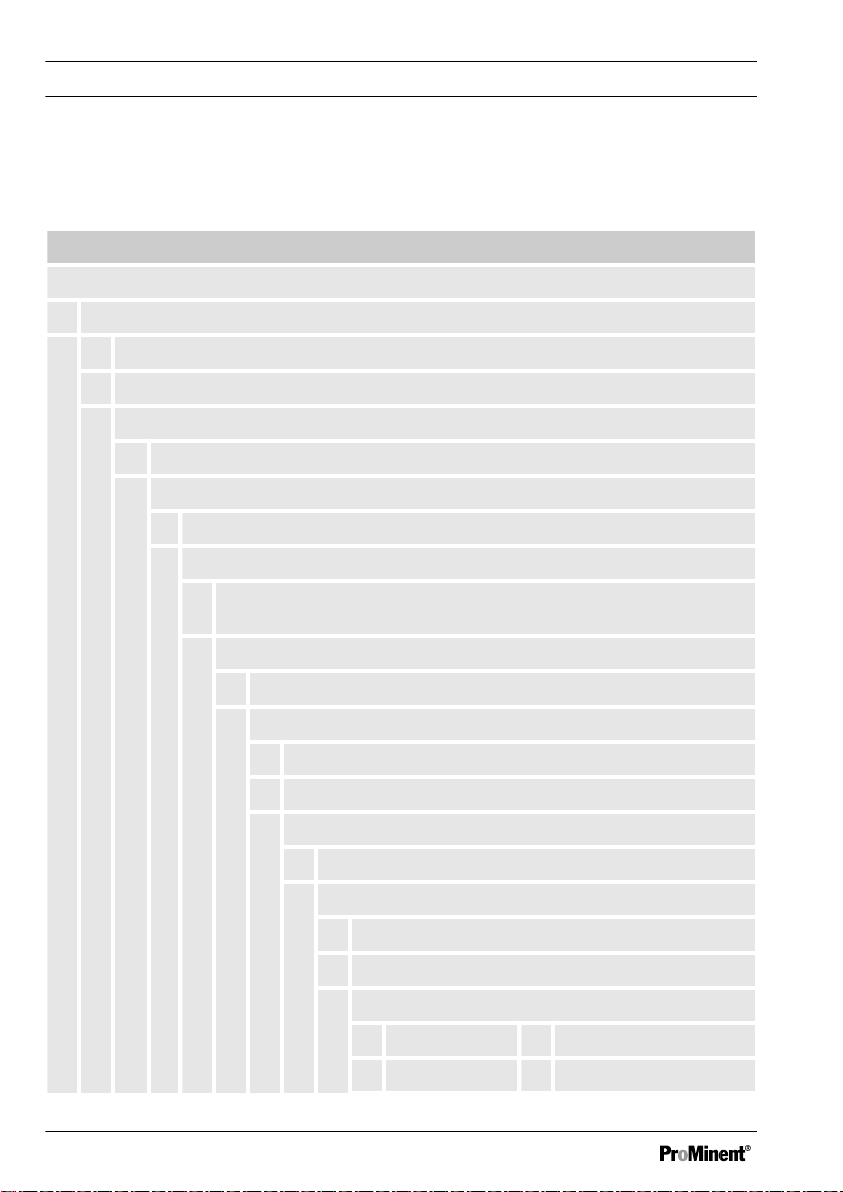
1.5 ID Code
Device identification / Identcode
DULCOMETER® controller series D1Cb / D1Cc
D1Cb / D1Cc
Type of mounting
W Wall mounted D1Cb (IP 65)
D Control panel installation D1Cc (IP54)
Version
00 with LCD and keypad / with ProMinent logo
Operating voltage
6 90...253 V, 50/60 Hz (wide voltage power unit)
Certification
01CE mark
Hardware extension I
14
0 none
Hardware extension II
0 none
1 Protective RC circuit for power relay
External connection
0 none
Software default setting
U Default setting
V Software preset
Default measured variable
0 Universal I Chlorite
A Peracetic acid P pH
Page 15
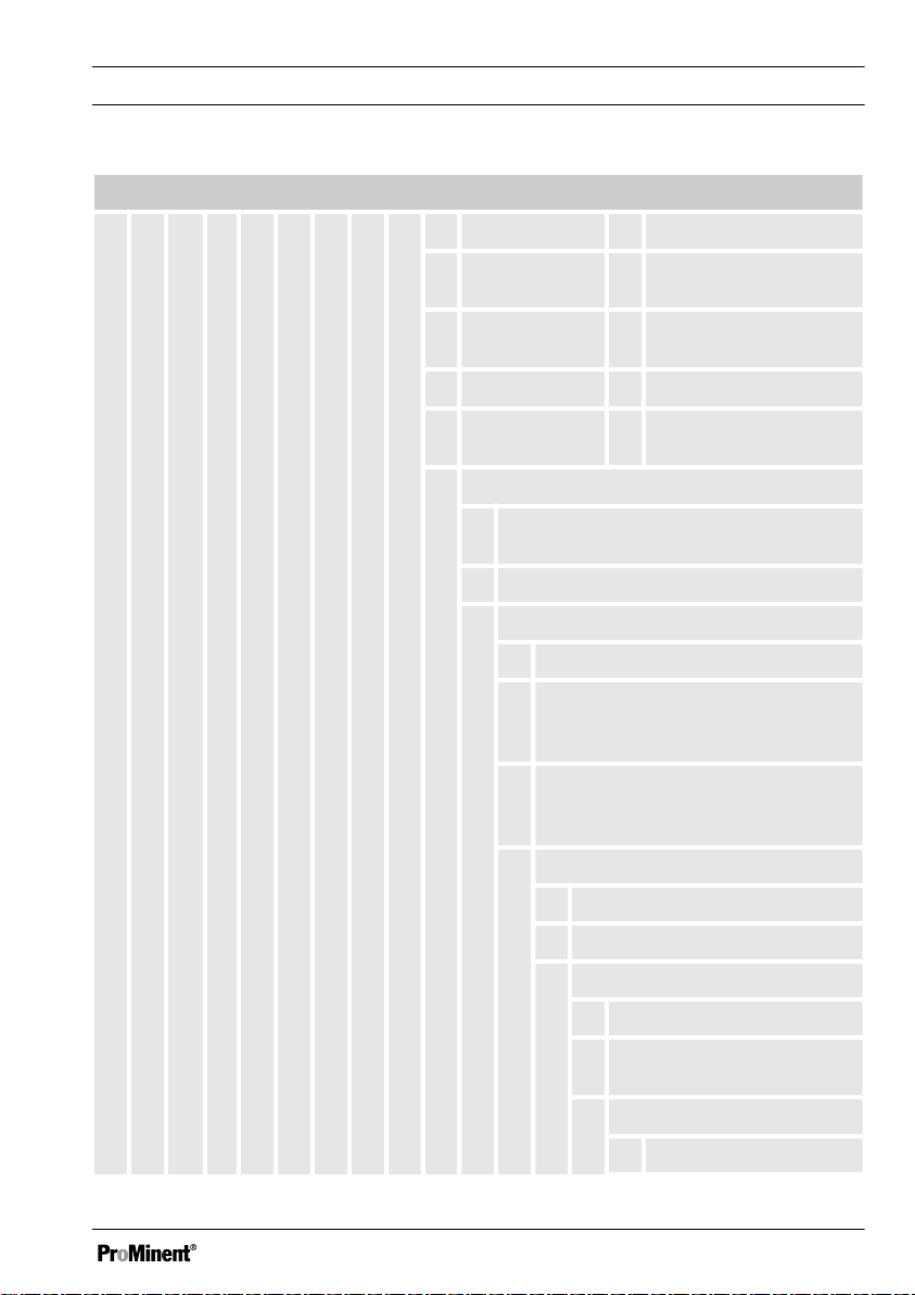
DULCOMETER® controller series D1Cb / D1Cc
B Bromine R ORP
Introduction
C Chlorine S 0/4...20 mA standard
signal general
D Chlorine
X Dissolved oxygen
dioxide
F Fluoride Z Ozone
H Hydrogen per‐
L Conductivity
oxide
Connection of the measured variable
1 mA input (standard signal 0/4-20 mA, all
measured variables)
5 mV input (pH/ORP)
Correction variable
0 none
2 Temperature Pt 100/PT1000 (for
pH, conductivity, fluoride, ClO2 CDP
sensor)
4 Manual temperature input (for pH,
conductivity, fluoride, ClO2 CDP
sensor)
Control input
0 none
1 Pause
Signal output
0 none
1 Analogue signal output
0/4...20 mA
Power activation
G Alarm and 2 limit relays
15
Page 16
Introduction
DULCOMETER® controller series D1Cb / D1Cc
M Alarm and 2 solenoid
valve relays
Pump activation
0 none
2 2 pumps via pulse
frequency
Control character‐
istic
0 none
1 Proportional
control
2 PID control
16
Page 17

Functional description
2 Functional description
Brief functional description
The DULCOMETER® D1Cb / D1Cc 4-wire measuring transducer/controller is a device
designed to measure/control a measured variable.
In the mA measuring version, the measured variable can be changed without restrictions
in the device menu. In the mV measurement version, the menu of the
DULCOMETER®
Depending on the measured variable, sensors for pH or redox potential (ORP) or
amperometric sensors can only be connected to the measured variables in line with
Ä ‘Allocation of the measurement inputs of the DULCOMETER® D1Cb / D1Cc’ Table
on page 17
measured using a Pt 100/1000. This means that automatic temperature compensation is
possible with pH-value, conductivity and fluoride measured variables. Temperature com‐
pensation is performed in the sensor (with the exception of the chlorine dioxide sensor
type CDP) with amperometric measured variables (chlorine etc.). Operation of the
DULCOMETER® D1Cb / D1Cc takes place via the menu keys. and the data is displayed
by means of an illuminated LCD display. The LCD display ensures that the measured
value, correction variable, control value and error messages can be clearly read.
Allocation of the measurement inputs of the DULCOMETER® D1Cb / D1Cc
D1Cb / D1Cc only permits choice between pH and ORP.
. The temperature measurement serves as a correction variable and can be
Connection of the measured vari‐
able to:
Character Measured variable mV input mA input
0 no default setting
of the measured variable
X
(pH and redox can be selected)
A PES (peracetic acid) X
B Bromine X
C Chlorine X
D Chlorine dioxide X
F Fluoride X
*with measured value transducer
17
Page 18

Functional description
Connection of the measured vari‐
able to:
Character Measured variable mV input mA input
H H2O2 (hydrogen peroxide) X
I Chlorite X
P pH X X*
R ORP X X*
S 0/4...20 mA standard signal general X
X O
Z O
2
3
X
X
L Conductivity X
*with measured value transducer
Description of the terminal connections for mA and mV: see Fig. 11 and Fig. 12
Description of the operating menu of the measured variables via mV connection:
see
Ä Chapter 8 ‘Measured Variables and Operating Menus for Potentiometric Sensors’
on page 81
Description of the operating menu of the measured variables via mA connection: see
Ä Chapter 7 ‘Measured Variables and Operating Menus for Amperometric Sensors’
on page 69
Description of the operating menu of the measured variables via mA standard signal: see
Ä Chapter 9 ‘Measured Variables and Operating Menus for the Standard Signal General’
on page 101
2.1 Wall mounting/control panel installation
DULCOMETER® D1Cb
The DULCOMETER®
both for wall-mounting, as well as for
installation in a control panel (with addi‐
tional control panel mounting kit).
D1Cb W is suitable
The plastic housing comprises a housing
upper section and lower section. The LCD
display and membrane keypad are
accommodated in the upper section of the
housing.
The lower section of the housing accom‐
modates the processor and power units
and any optional assemblies. A ribbon
cable connects to the LCD display and the
membrane keypad.
18
Page 19

The electrical connection is made through
originally sealed, push-out cable cut-outs
on the underside of the lower section of
the housing.
A wall bracket for wall mounting is located
on the rear of the lower section of the
housing.
DULCOMETER® D1Cc
The DULCOMETER® D1Cc is suitable for
control panel installation. In this respect if
fulfils the same functions as the D1Cb.
However, the D1Cc also has an option for
upgrading with a protective RC circuit.
When correctly installed, the D1Cc has an
IP54 protection rating.
Electrical construction
2.2
The device does not have a mains switch.
It is therefore immediately ready for ope‐
ration once connected to the power
supply.
The device processes an input signal
whilst taking into consideration operator
inputs. The result is displayed and made
available to other devices via a standard
signal. When equipped with actuators, the
device can also provide control functions.
It is designed to activate metering pumps,
solenoid valves, as well as an mA
standard signal output. The activation var‐
iable is recalculated every second.
Functional description
19
Page 20
externer Speicher /
EEROM/Flash
mV Eingang /
mA Eingang /
Kontakteingang
Netzteil
Temperatureingang /
Relaisausgang 3 /
Relaisausgang 2 /
Relaisausgang 1 /
Kontaktausgang 1 /
Kontaktausgang 2 /
Stromausgang /
Functional description
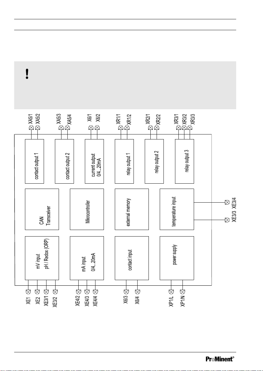
2.2.1 Block circuit diagram
NOTICE!
Connection of mV or mA sensors
The DULCOMETER® D1Cb / D1Cc is suitable for the connection of mV or mA sen‐
sors. It is not possible to connect mV and mA sensors simultaneously.
Fig. 1: Block circuit diagram
20
Page 21

Netzeingang /
Netzanschluss
pH Eingang /
mA Eingang /
Kontakteingang /
Temperatureingang /
Kontaktausgang 2 /
Kontaktausgang 1 /
mA Ausgang /
Alarmausgang /
Relaisausgang 1-2 * /
Functional description
2.2.2 Galvanic Isolation
WARNING!
Protective low voltage/Mains voltage
Possible consequence: Fatal or very serious injuries
If relay 1 or 2 is operated with protective low voltage, no mains voltage may be con‐
nected to the other relay.
Fig. 2: Galvanic Isolation
* If relay 1 or 2 is operated with protective low voltage, no mains voltage many be con‐
nected to the other relay.
** No galvanic isolation between mA and mV input and temperature input.
21
Page 22
D1Cb mounting
3 D1Cb mounting
n User qualification, mechanical
mounting: trained qualified personnel,
see
Ä Chapter 1.2 ‘Users' qualifica‐
tions’ on page 10
n User qualification, electrical installa‐
tion: Electrical technician, see
Ä Chapter 1.2 ‘Users' qualifications’
on page 10
NOTICE!
Mounting position and conditions
– Ensure that there is unimpeded
access for operation
Secure, low-vibration fixing
–
– Avoid direct sunlight
– Permissible ambient temperature
at fixing position: 0 ... 50 °C at
max. 95 % relative air humidity
(non-condensing)
NOTICE!
Material damage to electrostatically
sensitive components
Components can be damaged or
destroyed by electrostatic voltages.
– Before any work, on electrostati‐
cally sensitive components, dis‐
connect the power supply.
When working on electrostatically
–
sensitive components, wear an
earthed anti-static wrist band.
– Always hold components by their
corners and never touch conduc‐
tors, ICs, etc.
– Only place components on anti-
static supports or the original
packaging.
22
Ablese- und Bedienposition
–
Das Gerät in einer günstigen
Ablese- und Bedienposition
(möglichst in Augenhöhe) mon‐
tieren
Montageposition
–
Ausreichend Freiraum für die
Kabel vorsehen
–
Für die ‘Parkstellung’ des
Reglers, nach oben mindestens
120 mm Platz freihalten
Page 23

3.1 Scope of supply
The following parts belong to the standard
scope of supply of a
DULCOMETER
series D1Cb controller.
Identifier Quantity
D1Cb controller 1
®
D1Cb mounting
Half screw connection, com‐
plete (set)
M12 x 1.5 threaded connec‐
tion, complete (set)
Assembly material, complete,
3P Universal (set)
Measured variable labels
D1C/D2C
Operating Manual 1
General safety notes 1
1
1
1
1
23
Page 24
D1Cb mounting
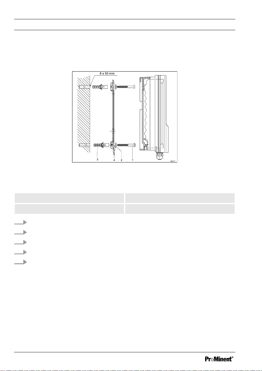
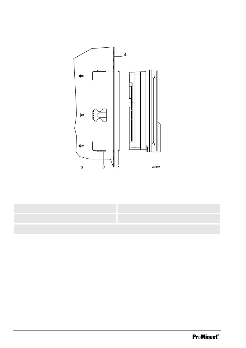
3.2 Installation (Wall Mounted)
The device can be installed directly on the wall with the aid of the wall bracket.
Fig. 3: Fixing material for wall mounting
1. 3 x Round head screws 5x45 2. 3 x Washers 5.3
3. 3 x Plastic wall plugs d8 4. Wall bracket
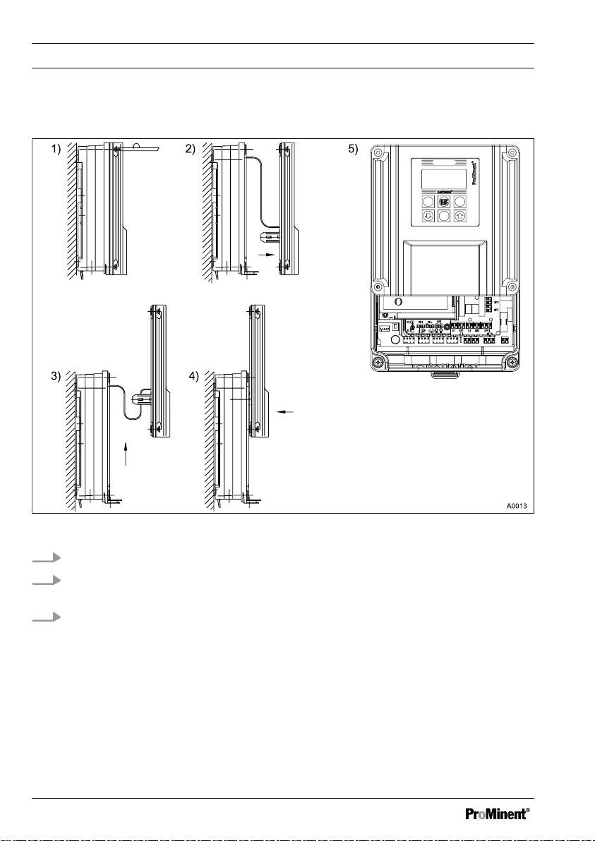
1. Mark the holes using the wall bracket and drill them
2. Insert wall plugs
3. Secure wall bracket in place with washers and round head screws
4. Place the device from above onto the wall bracket
5. Press the device gently against the wall bracket and slide it approx. 4 mm upwards
until you hear it engage in position
24
Page 25
D1Cb mounting
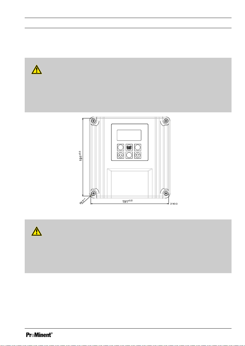
3.3 Installation - Control Panel Mounted (Optional)
CAUTION!
Dimensional variations
Possible consequence: material damage
– Photocopying the punched template can result in dimensional deviations
Use the dimensions shown in Fig. 4 and mark on the control panel
–
Fig. 4: Punched template, drawing number 3140-3 /not to scale
CAUTION!
Material thickness of control panel
Possible consequence: material damage
– The material thickness of the control panel must be at least 2 mm to ensure
secure fixing
25
Page 26
D1Cb mounting
Fig. 5: The material thickness of the control panel must be at least 2 mm to ensure
secure fixing
1. 1 x Foam rubber caulk strip d3 2. 6 x Galvanised steel retaining brackets
3. 6 x Galvanised PT cutting screws 4. Control panel
For the part number of the assembly set, refer to
26
Ä Table on page 149
Page 27
D1Cb mounting
1. Using the dimensions shown in
Fig. 4 mark the precise position of the device on
the control panel
2. Mark the corner points and drill (drill diameter 12 - 13 mm)
3. With a punching tool or jigsaw make the opening as per the punched template
drawing
4. Chamfer the cut edges and check whether the sealing surfaces are smooth for the
caulk strip
Otherwise the seal cannot be guaranteed
ð
5. Press the caulk strip evenly into the groove running around the device
6. Place the device into the control panel and fix in place at the rear by means of the
retaining brackets and PT cutting screws
The device should project approx. 35 mm from the control panel
ð
3.4 Wall Mounted Installation of
D1Cb (Electrical)
WARNING!
Electrical voltage
Possible consequence: Fatal or very
serious injuries
– The electrical connection to the
device should only be made once
it has been fitted to the wall or
control panel
The device must be electrically
–
disconnected before it is opened
– Ensure that the device cannot be
reconnected accidentally
NOTICE!
Opening the device
Damage to the product or its sur‐
roundings
– The device may only be opened
by qualified personnel
The device should only be
–
opened when fitted to the wall or
control panel
27
Page 28
D1Cb mounting
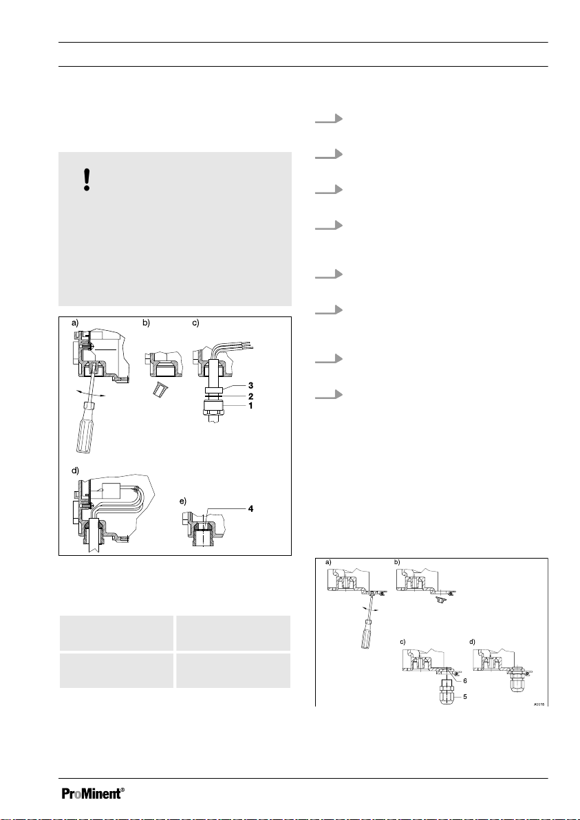
3.4.1 Opening the device
Fig. 6: Opening the device
1. Loosen the 4 captive screws (1).
2. Lift the upper section of the device from the lower section (2). A wide flathead
screwdriver may be of assistance.
3. Insert the upper section with both guide rails into the lower section (3 and 4)
(parked position)
28
Page 29
A0014
D1Cb mounting
3.4.2 Electrical Installation (Wall Mounted)
NOTICE!
Threaded holes
Using a suitable tool, punch out the
threaded holes according to the
number of cables ( Æ approx. 4 mm).
– Punch aids are provided to punch
out the threaded holes
1. Remove cable sheathing over a
sufficient length
2. Fit screw connection (1), pressure
ring (2) and seal (3) onto cable
3. Insert cable and fittings into the
threaded hole
4. Align the cable and push in until
enough cable is in the control
housing
5. Screw in screw connection and
tighten firmly
6. Shorten cable wires to the precise
overall length and strip off approx. 8
mm insulation
7. Fit cable end sleeves to the wires.
Refer to
Ä on page 32
8. Connect up the wires to the termi‐
nals according to the electrical
wiring diagram Fig. 11
Punched out threaded holes can be
resealed with the M20 dummy washers
(4) provided.
The M12 x 1.5 screw connections and
brass lock nuts are used for the 4 open‐
ings in the front row.
Fig. 7: Punching out the threaded holes
1. Screw connec‐
tion M20 x 1.5
3. Pressure ring
M20
2. Pressure ring
M20
4. Dummy washer
M20
Fig. 8: M12x1.5 screw connections
29
Page 30

D1Cb mounting
5. Screw connec‐
tion M12 x 1.5
6. Lock nut
M12x1.5
1. Fit lock nut M12x1.5 (6) on the
inside
2. Fit screw connection M12x1.5 (5)
from the outside and tighten firmly
3.4.3
Electrical Installation (Control Panel Mounted)
Proceed as described under "Electrical
Installation (Wall Mounted)". Refer to
Ä Chapter 3.4.2 ‘ Electrical Installation
(Wall Mounted) ’ on page 29
Only the rear row of threaded holes
(M20x1.5) should be used when the
device is mounted in a control panel. The
front row (M12x1.5) lies outside of the
control panel.
Connect up as per the electrical terminal
wiring diagram. Refer to
Ä Chapter 3.4.7
‘Terminal Wiring Diagram ’ on page 34
30
Page 31

D1Cb mounting
3.4.4 Installation of Coaxial Cable to Guard Terminal XE1
CAUTION!
Maximum length of the coaxial cable 10 m
Incorrect reading due to too long a coaxial cable
Possible consequence: Slight or minor injuries, material damage
The maximum length of the coaxial cable may not exceed 10 m when using redox or
pH sensors. The measured signal can otherwise be falsified by the effects of interfer‐
ence.
If the gap between the pH/redox measuring point and the
more than 10 metres, then the use of an interposed DULCOTEST ® transducer 4-20
mA pH V1, rH V1 is recommended. The connection is then made via terminal XE4 of
the DULCOMETER ® D1Cb.
The XE4 (mA input) terminal is a chargeable additional function!
DULCOMETER ® D1Cb is
When installing the coaxial cable for the guard terminal XE 1, the allowances shown on
the diagram for stripping insulation from the coaxial cable should be adhered to.
Fig. 9
The guard terminal should be tightened until "hand-tight".
31
Page 32

optional
RC-Schutzbeschaltung
Sicherung
Programmierschnittstelle
Schirmklemme
Klemmenanordnung Ausführung Wandgerät
Konfektionierung Koaxialkabel zum Anschluss an D1Cb
oder vorkonfektioniert in den Varianten
Detail Anschluss Koaxialkabel D1Cb
D1Cb mounting
Fig. 9: Preparation of coaxial cable
3.4.5 Cable Cross-Sections and Cable End Sleeves
Minimum cross-sec‐
Without cable end
tion
0.25 mm
2
sleeve
Cable end sleeve
without insulation
Cable end sleeve
0.20 mm
0.20 mm
2
2
with insulation
32
Maximum crosssection
1.5 mm
1.0 mm
1.0 mm
Stripped insulation
length
2
2
2
8 - 9 mm
10 - 11 mm
Page 33

3.4.6 Protective RC Circuit (Optional)
A protective RC circuit is recommended
for operation with consumers, which
present an inductive load (e.g. motor
metering pumps or solenoid metering
pumps). In these applications a protective
RC circuit prevents wear and tear of the
relay contacts. Refer to
Ä ‘Spare parts
and accessories DULCOMETER® D1Cb’
on page 148
D1Cb mounting
33
Page 34

Klemmenanordnung
Ausführung: Wandmontage
Schirmklemme
Sicherung 5x20
D1Cb mounting
3.4.7 Terminal Wiring Diagram
Fig. 10: Terminal layout
34
Page 35

Netz
Netz
Magnetventil 2(senken)
Magnetventil 1(heben)
Netz Netz
Relais 3 / Alarm
Grenzwertrelais 1
Grenzwertrelais 2
Extern
Belegungsvarianten
Variante 1
Magnetventil
Grenzwertrelais, Timer, Stellglied
(ohne RC-Schutzbeschaltung)
Variante 2
Variante 2
Variante 1
D1Cb mounting
Fig. 11: Terminal diagram with assignment options 1
35
Page 36

Netz
Normsignal-Eingang
Temperatur
Digital Eingang "Pause" oder Störgröße
Offen/geschl.
Potenzialfreier Kontakt nötig!
Drahtbrücke
-
ProMinent Umformer
Normsignal-Eingang
Stromquelle
Extern Pumpe 2,senken (potenzialfrei)
Extern Pumpe 1,heben (potenzialfrei)
Normsignal-Ausgang1
1
Belegungsvarianten
Temperatur
Potenzialausgleich
Belegungsvarianten
D1Cb mounting
Fig. 12: Terminal diagram with assignment options 2
36
Page 37

Extern
Netz
Pumpe 2 (senken)
Pumpe 1 (heben)
RC-Schutzbeschaltung
(optional)
D1Cb mounting
Fig. 13: Protective RC circuit terminal diagram
37
Page 38

A0842
D1Cb mounting
3.5 Switching of inductive loads
If you connect an inductive load, i.e. a
consumer which uses a coil (e.g. an
alpha motorised pump), then you
must protect your controller with a
protective circuit. If in doubt, consult
an electrical technician for advice.
The RC member protective circuit is a
simple, but nevertheless very effective,
circuit. This circuit is also referred to as a
snubber or Boucherot member. It is pri‐
marily used to protect switching contacts.
When switching off, the connection in
series of a resistor and capacitor means
that the current can fade out in a damped
oscillation.
Also when switching on, the resistor acts
as a current limiter for the capacitor
charging process. The RC member pro‐
tective circuit is highly suited to AC
voltage supplies.
C=k * I
L
k=0,1...2 (dependent on the application).
Only use capacitors of class X2.
Units: R = Ohm; U = Volt; IL = Ampere;
C = µF
If consumers are connected which
have a high starting current (e.g. plugin, switched mains power supplies),
then a means of limiting the starting
current must be provided.
The switching-off process can be investi‐
gated and documented using an oscillo‐
scope. The voltage peak at the switch
contact depends on the selected RC com‐
bination.
The magnitude of the resistance R of
the RC member is determined according
to the following equation:
R=U/I
L
(U= Voltage divided by the load // IL =
load current)
The magnitude of the capacitor is deter‐
mined using the following equation:
Units: R = Ohm; U = Volt; IL = Ampere;
C = µF
38
Fig. 14: Switching-off process shown on
the oscillogram.
Page 39

WARNING!
A0835
Mains voltage
Possible consequence: Fatal or very
serious injuries
If mains voltage is connected to one
of the terminals XR1-XR3 or XP, then
no protective low voltage may be con‐
nected to any other of these terminals
(SELV).
D1Cb mounting
Fig. 15: RC protective circuit for the relay
contacts
Typical AC current application with an
inductive load:
n 1) Load (e.g. alpha motorised pump)
n 2) RC-protective circuit
– Typical RC protective circuit at
230 V AC:
– Capacitor
– Resistor
[0.22µF/X2]
[100 ohm / 1 W]
(Metal-
oxide (pulse-resistant))
n 3) Relay contact (XR1, XR2, XR3)
39
Page 40

D1Cc mounting
4 D1Cc mounting
n User qualification, mechanical
mounting: trained qualified personnel,
see
Ä Chapter 1.2 ‘Users' qualifica‐
tions’ on page 10
n User qualification, electrical installa‐
tion: Electrical technician, see
Ä Chapter 1.2 ‘Users' qualifications’
on page 10
NOTICE!
Mounting position and conditions
– Ensure that there is unimpeded
access for operation
Secure, low-vibration fixing
–
– Avoid direct sunlight
– Permissible ambient temperature
at fixing position: 0 ... 50 °C at
max. 95 % relative air humidity
(non-condensing)
NOTICE!
Material damage to electrostatically
sensitive components
Components can be damaged or
destroyed by electrostatic voltages.
– Before any work, on electrostati‐
cally sensitive components, dis‐
connect the power supply.
When working on electrostatically
–
sensitive components, wear an
earthed anti-static wrist band.
– Always hold components by their
corners and never touch conduc‐
tors, ICs, etc.
– Only place components on anti-
static supports or the original
packaging.
40
Ablese- und Bedienposition
–
Das Gerät in einer günstigen
Ablese- und Bedienposition
(möglichst in Augenhöhe) mon‐
tieren
Montageposition
–
Ausreichend Freiraum für die
Kabel vorsehen
Page 41

D1Cc mounting
4.1
DULCOMETER®
The following parts belong to the standard scope of supply of a DULCOMETER® series
D1Cc controller.
Identifier Quantity
D1Cc controller 1
Retaining bracket 4
Measured variable labels D1C/D2C 1
Operating Manual 1
General safety notes 1
4.2
Mounting - control panel installation DULCOMETER® D1Cc
CAUTION!
Dimensional variations
Possible consequence: material damage
– Photocopying the punched template can result in dimensional deviations
Use the dimensions according to Fig. 16 and mark on the control panel
–
D1Cc scope of supply
CAUTION!
Material thickness of control panel
Possible consequence: material damage
– The material thickness of the control panel must be at least 2 mm to ensure
secure fixing
The device is designed for installation in a control panel. The housing corresponds to DIN
43700. The control panel opening for installation of the device is specified in DIN 43700.
We recommend a smaller opening. Fixing of the device is then better (less sideways
play) and the seal is uniformly compressed.
41
Page 42

92
+0,6
92
+0,6
90
+0,5
90
+0,5
I. II.
A0696
D1Cc mounting
Fig. 16: Mounting - control panel installation DULCOMETER® D1Cc
I. DIN 43700 instruction
II. ProMinent recommendation
42
Page 43

®®
STOP
S
T
A
RT
DULCOM
ETER
®
D
1
C
A0697
D1Cc mounting
Fabricating the opening:
Fig. 17: Screw the studs forward
A drilling punched 1:1 template is enclosed with the device as a mounting aid. Its use
will ensure optimal positioning of the device on the control panel.
1. Align and secured the punched drilling template in the appropriate position on the
control panel using a spirit level
2. Mark the four corners using a centre punch and drill four holes using a 6 mm Ø bit
3. Then saw out the connected bridges with a jigsaw
4. Dress the surfaces so they are smooth and the dimensions are within the specified
tolerance.
5. Finally ensure the edges are fully de-burred
6. Before inserting the device in the control panel opening, check the position of the
seal (must lie against the front collar)
IP54 protection rating
43
Page 44

D1Cc mounting
7. Insert the device from the outside in the opening, attach the retaining bracket and
push backwards up to the stop
All four holes retaining brackets must be attached, as otherwise protection
ð
rating IP54 cannot be adhered to.
8. Using a suitable screw driver, screw the studs forwards, see
Fig. 17, until the seal
is completely and uniformly compressed
9. Check the correct seating of the seal, as necessary loosen the studs and correct
the position
4.3 Electrical Installation (Con‐
trol Panel Mounted)
Connect up as per the electrical terminal
wiring diagram. Refer to
‘Terminal diagram ’ on page 48
Ä Chapter 4.3.3
44
Page 45

D1Cc mounting
4.3.1 Installation of Coaxial Cable to Guard Terminal XE1
CAUTION!
Maximum length of the coaxial cable 10 m
Incorrect measured value due to too long a coaxial cable
Possible consequence: Slight or minor injuries. Material damage.
The maximum length of the coaxial cable may not exceed 10 m when using redox or
pH sensors. The measurement signal can otherwise be falsified by the effects of
interference.
If the distance between the pH/ORP measuring point and the
is more than 10 m, the use of a DULCOTEST® measuring transducer 4-20 mA pH
V1, rH V1 is recommended. Connection is then via terminal XE4 of the
DULCOMETER® D1Cc
The XE4 (mA input) terminal is an auxiliary function that incurs an extra charge.
When installing the coaxial cable for the guard terminal XE 1, the allowances shown in
the diagram Fig. 18 for stripping insulation from the coaxial cable must be adhered to.
The guard terminal should be tightened until "hand-tight".
DULCOMETER® D1Cc
45
Page 46

Terminal order panel type mounting
Fabrication of the coaxial cable connection to the D1Cc
or pre-fabricated for the variants
A0698
D1Cc mounting
Fig. 18: Preparation of coaxial cable
46
Page 47

4.3.2 Cable Cross-Sections and Cable End Sleeves
D1Cc mounting
Minimum cross-sec‐
tion
Without cable end
0.25 mm
2
sleeve
Cable end sleeve
0.20 mm
2
without insulation
Cable end sleeve
0.20 mm
2
with insulation
Maximum crosssection
1.5 mm
1.0 mm
1.0 mm
2
2
2
Stripped insulation
length
8 - 9 mm
10 - 11 mm
47
Page 48

Netz
Netz
Magnetventil 2(senken)
Magnetventil 1(heben)
Netz Netz
Relais 3 / Alarm
Grenzwertrelais 1
Grenzwertrelais 2
Extern
Belegungsvarianten
Variante 1
Magnetventil
Grenzwertrelais, Timer, Stellglied
(ohne RC-Schutzbeschaltung)
Variante 2
Variante 2
Variante 1
D1Cc mounting
4.3.3 Terminal diagram
Fig. 19: Terminal diagram with assignment options 1
48
Page 49

Netz
Normsignal-Eingang
Temperatur
Digital Eingang "Pause" oder Störgröße
Offen/geschl.
Potenzialfreier Kontakt nötig!
Drahtbrücke
-
ProMinent Umformer
Normsignal-Eingang
Stromquelle
Extern Pumpe 2,senken (potenzialfrei)
Extern Pumpe 1,heben (potenzialfrei)
Normsignal-Ausgang1
1
Belegungsvarianten
Temperatur
Potenzialausgleich
Belegungsvarianten
D1Cc mounting
Fig. 20: Terminal diagram with assignment options 2
49
Page 50

A0842
D1Cc mounting
4.4 Switching of inductive loads
If you connect an inductive load, i.e. a
consumer which uses a coil (e.g. an
alpha motorised pump), then you
must protect your controller with a
protective circuit. If in doubt, consult
an electrical technician for advice.
The RC member protective circuit is a
simple, but nevertheless very effective,
circuit. This circuit is also referred to as a
snubber or Boucherot member. It is pri‐
marily used to protect switching contacts.
When switching off, the connection in
series of a resistor and capacitor means
that the current can fade out in a damped
oscillation.
Also when switching on, the resistor acts
as a current limiter for the capacitor
charging process. The RC member pro‐
tective circuit is highly suited to AC
voltage supplies.
C=k * I
L
k=0,1...2 (dependent on the application).
Only use capacitors of class X2.
Units: R = Ohm; U = Volt; IL = Ampere;
C = µF
If consumers are connected which
have a high starting current (e.g. plugin, switched mains power supplies),
then a means of limiting the starting
current must be provided.
The switching-off process can be investi‐
gated and documented using an oscillo‐
scope. The voltage peak at the switch
contact depends on the selected RC com‐
bination.
The magnitude of the resistance R of
the RC member is determined according
to the following equation:
R=U/I
L
(U= Voltage divided by the load // IL =
load current)
The magnitude of the capacitor is deter‐
mined using the following equation:
Units: R = Ohm; U = Volt; IL = Ampere;
C = µF
50
Fig. 21: Switching-off process shown on
the oscillogram.
Page 51

WARNING!
A0835
Mains voltage
Possible consequence: Fatal or very
serious injuries
If mains voltage is connected to one
of the terminals XR1-XR3 or XP, then
no protective low voltage may be con‐
nected to any other of these terminals
(SELV).
D1Cc mounting
Fig. 22: RC protective circuit for the relay
contacts
Typical AC current application with an
inductive load:
n 1) Load (e.g. alpha motorised pump)
n 2) RC-protective circuit
– Typical RC protective circuit at
230 V AC:
– Capacitor
– Resistor
[0.22µF/X2]
[100 ohm / 1 W]
(Metal-
oxide (pulse-resistant))
n 3) Relay contact (XR1, XR2, XR3)
51
Page 52

language
Deutsch
english
A0201_GB
Commissioning
5 Commissioning
n Users' qualification: Trained user
WARNING!
Sensor run-in periods
This can result in hazardous incorrect
metering
Take into consideration run in periods
when commissioning
Correct measuring and dosing is
–
only possible if the sensor is
working perfectly
– It is imperative that the run in
periods of the sensors are
adhered to
– The run in periods should be
allowed for when planning com‐
missioning
– It may take a whole working day
to run-in the sensor
– Please read the operating manual
for the sensor
Start menu during initial commis‐
sioning
The "Language setting during initial
commissioning" menu appears only
once.
Later changes to the operating lan‐
guage can then be made via the
"General Settings/Information" menu
item.
Fig. 23: Initial commissioning display
This is followed by the selection of the
measured variable and the measuring
range in the "General Settings/Informa‐
tion" menu item.
Following completion of mechanical and
electrical assembly, the controller should
be integrated into the measuring point.
Initial commissioning
5.1
During initial commissioning the device's
display will be in "English". The display
will show "language english". Exception:
the language has been factory-preset to
the customer's requirement.
52
5.1.1 Selection of the Operating Language
With devices, which have not been pre‐
configured to the customer's specific
requirement, the operating language
required has to be selected in the "Gen‐
eral Settings / Operating Menu/" menu.
Refer to
Ä Chapter 10.6 ‘General settings’
on page 131
Page 53

NOTICE!
Resetting the operating language
In the event that a foreign and thus
non-comprehensible operating lan‐
guage has been set, the
DULCOMETER® D1Cb / D1Cc can
be reset to the basic "English" setting.
If you find yourself in the continuous
display 1, then by simultaneously
pressing the keys
, , the
DULCOMETER® D1Cb / D1Cc can
be made to ask again for the oper‐
ating language. Refer to
Ä Chapter 6.3 ‘Permanent Display 1 ’
on page 61
Should you no longer know where
you are in the operating menu,
because you cannot read the strange
operating language, then press key
10 times. Then you will definitively
find yourself in continuous display 1.
Commissioning
53
Page 54

general setting
Information
Identcode:
Vxxxxxxxxxxxx
D1CBxxxxxxxxxxx
Srnr: xxxxxxxxxx
add. functions
Software version
measure change
wash timer chlorit
Br
O3
O2
effective range
A0032
0...2.00ppm
Commissioning
5.1.2 Selection of the Measured Variable and Measuring Range
WARNING!
Incorrect metering due to incorrect measuring range
Possible consequence: Fatal or serious injuries.
– The measuring range of the sensor is essential for the measuring range!
If the assignment of the measuring range is modified, the settings must be
–
checked in all menus
– If the assignment of the measuring range is changed, the sensor must be recali‐
brated
With devices, which have not been preconfigured to the customer's specific requirement,
the measured variable required has to be selected in the complete operating menu "Gen‐
eral Settings / Change Measured Variable". The DULCOMETER® D1Cb / D1Cc then has
to be labelled with the label corresponding to the measured variable selected. The rele‐
vant labels are enclosed with the DULCOMETER® D1Cb / D1Cc.
Fig. 24: Selection of measured variable and measuring range
The measuring range required has to be selected and set in the complete operating
menu General Settings / Change Measured Variable, see
Measured Variable/Measuring Range’ on page 131
54
Ä Chapter 10.6.1 ‘Setting the
.
Page 55

general setting
informationen
Identcode:
Vxxxxxxxxxx
D1CB xxxxxxxxx
Srnr: xxxxxxxxxx
add. functions
software version
measure change
wach timer
function
unlocking
yes
no
Code input:
_ _ _ _ - _ _ _ _ _ _ _ _ - _ _ _ _
A0010_GB
Code ok!
wrong code!
Commissioning
5.2 Activation Code for Extended Functions
Activation code
Access to further functions can optionally be provided by means of an activation
code.
Should you require additional operating literature for these functions, this can be
obtained on the homepage of ProMinent Dosiertechnik, Heidelberg.
Fig. 25: Activation code / Serial number
The activation code is entered one digit at a time using the
next position using the
5.2.1 Extended Functions Obtain‐
Extended functions
The DULCOMETER® D1Cb / D1Cc con‐
troller functionality can be extended or
modified by means of a 16-digit activation
code. Functions can be enabled several
times.
and keys. Move to the
key.
The newly activated functions must be configured or parameterised in the relevant
menu or new measured variables must be calibrated. Information on this can be
found in the relevant complete operating menu.
able with the Activation Code
D1Cb / D1Cc software upgrade
To provide an activation code, ProMi‐
nent requires the 10-digit serial
number (Srnr) and the required soft‐
ware upgrade identity code, which
can both be found in the table below.
55
Page 56

Commissioning
NOTICE!
Activation code
When ordering the activation code, it
is imperative that you ensure that the
serial number (Srnr) corresponds
exactly to that of the DULCOMETER
D1Cb / D1Cc. Otherwise a charge‐
able activation code will be provided,
which will not work.
NOTICE!
"Incorrect code" message
If the code has been entered incor‐
rectly then the "Incorrect code" mes‐
sage will appear. You can enter the
activation code as many times as you
need to. If this is still not successful,
then check the serial number of the
controller.
®
56
Page 57

DULCOMETER® D1Cb / D1Cc software upgrade
D1UbSoftware default setting
V Software preset
Default setting - measured variable
0 Universal
A Peracetic acid
B Bromine
C Chlorine
D Chlorine dioxide
F Fluoride
H Hydrogen peroxide
I Chlorite
P pH
R ORP
Commissioning
S 0/4-20 mA standard signal general
X Oxygen
Z Ozone
L Conductivity
Connection of the measured variable
1* Standard signal 0/4-20 mA, all measured variables
5 mV input for pH/redox via guard terminal
Correction variable
0 none
2* Temperature Pt100/PT1000 (for pH and conductivity)
4* Manual temperature input (for pH and conductivity)
* = chargeable option
57
Page 58

Commissioning
DULCOMETER® D1Cb / D1Cc software upgrade
Control input
0 none
1* Pause
Signal output
0 none
1* Analogue signal output 0/4-20 mA
Power activation
G Alarm and 2 limit relays
M* Alarm and 2 solenoid valve relays
Pump activation
0 none
2* 2 pumps via pulse fre‐
quency
Control characteristic
* = chargeable option
58
0 none
1* Proportional control
2* PID control
Language
00 no default
setting
Page 59

Operating diagram/ Display Symbols
6 Operating diagram/ Display Symbols
Overview of equipment/Control elements
6.1
Fig. 26: Overview of equipment/Control elements
Function Description
1st respective measured variable Affix the measured variable label here.
2. Display
3. START/STOP key Start/Stop the control and metering functions
4. ENTER key To apply, confirm or save a displayed value or
status or to acknowledge an alarm
59
Page 60

Operating diagram/ Display Symbols
Function Description
5. UP key To increase a displayed numerical value and to
change the variables (flashing display). move up in
the operating menu.
6. DOWN key To lower a displayed numerical value and to
change the variables (flashing display). To move
down in the operating menu.
7. BACK KEY Back to the continuous display or to the start of the
respective setting menu
8. CHANGE key To change within a menu level and to move from a
changeable variable to another changeable vari‐
able within a menu option. When inputting numer‐
ical values, the cursor moves one space on
6.2 Display Symbols
The display of the DULCOMETER® D1Cb / D1Cc
Meaning Comment Symbol
Limit transgression - relay 1 upper Symbol left
Limit transgression - relay 1 lower Symbol left
uses the following symbols:
Limit transgression - relay 2 upper Symbol right
Limit transgression - relay 2 lower Symbol right
Metering pump 1 activation off Symbol left
Metering pump 1 activation on Symbol left
Metering pump 2 activation off Symbol right
Metering pump 2 activation on Symbol right
Solenoid valve 1 activation off Symbol left
Solenoid valve 1 activation on Symbol left
60
Page 61

Operating diagram/ Display Symbols
Meaning Comment Symbol
Solenoid valve 2 activation off Symbol right
Solenoid valve 2 activation on Symbol right
Stop key pressed
Manual dosing
Fault
Measured value rises very quickly Trend of measured value dis‐
play
Measured value rises quickly Trend of measured value dis‐
play
Measured value rises slowly Trend of measured value dis‐
play
Measured value falls very quickly Trend of measured value dis‐
play
Measured value falls quickly Trend of measured value dis‐
play
Measured value falls slowly Trend of measured value dis‐
play
Measured value steady Trend of measured value dis‐
play
6.3 Permanent Display 1
1. Reading
2. Mass unit ("ppm" in this example)
3. Status of the actuators
4. Display of reading trend - falling /
rising
Fig. 27: Permanent Display 1
Not all symbols are visible simultane‐
ously in the permanent display 1. The
scope of the symbols depends on what
is required.
61
Page 62

100%
2.3
A0095_GB
0%
mea. val
feedfwd:
ctrlout:.
w =
5.0 ppm
Operating diagram/ Display Symbols
5. Measured variable ("chlorine" in this
example)
6. Status line
Not all symbols are visible simultane‐
ously in the permanent display 1. The
scope of the symbols depends on what
is required.
6.4 Continuous display 2
Fig. 28: Continuous display 2
The continuous display 2 shows all the
currently required information from the
DULCOMETER® D1Cb / D1Cc controller.
Switch to other displays by pressing
or .
or
6.5 Continuous display 3
Fig. 29: Continuous display 3
1. Current measured value in plain text
2. Bar graph display shows the current
measured value in relation to the
lower and upper measured value
limits
3. Displays the upper and lower limit of
the display
Switch to other displays by pressing or
or .
To set the lower and upper value (3) press
. The left-hand value will flash and can
be set using the or . Confirm the
entry with . Likewise, switching
between the left- and right-hand values (3)
occurs by pressing the key
This setting only changes the display
range of the bar graph, as it were
"zooming in" to a smaller range to obtain a
better resolution of the display in the main
display range of the measurement.
.
62
Page 63

This setting only changes the display
range of the bar graph! A change to
the measuring range of the
DULCOMETER® D1Cb / D1Cc is not
possible using this function.
Operating diagram/ Display Symbols
63
Page 64

Operating diagram/ Display Symbols
6.6 Operating diagram
Access code
–
Access to the setting menu can be blocked with an access code
–
If the access code has been correctly selected for a setting menu, then all of the
other setting menus are also accessible
Fundamentally the continuous displays 1 - 3 and the calibration menu are freely
accessible. All of the other menus can be disabled by the access code in such a
way that the set values are displayed but cannot be changed. The default value
of the access code is "5000".
–
If no key is pressed within 60 seconds, the device will return to the continuous
display 1, the access code is re-enabled and access is restricted
64
Page 65

Access code, correct
Parameter
setting
Calibration notes
Permanent
display 1
Permanent
display 3
Calibration
menu
V
arious
Access code
Setting menus
A0001_GB
Permanent
display 2
Operating diagram/ Display Symbols
Fig. 30: Access code
The number and scope of the setting menus depends on the design of the device.
65
Page 66

1
Text 1
Text 2
Selection 1
Selection 2
Text 1
Text 2
Selection 1
Selection 2
A0007_GB
Operating diagram/ Display Symbols
You can set and change numerical values as follows:
Fig. 31: Settable values flash on and off
1. Settable values flash on and off
You can lower or increase values using the keys
and .
You can switch between the settable values using the key.
1. The setpoint (e.g. 7.20 pH) flashes
2.
The the or key once
The first figure of the numerical value now flashes.
ð
3.
Using the
key you can go back to the figure you want to change
By pressing the key multiple times, you can return to the first figure of the
numerical value which is to be set.
The figure of the numerical value which can be changed flashes.
4.
66
You can lower or increase the numerical value using the keys and
Page 67

general setting
information
Identcode:
D1CB xxxxxxxxxx
Vxxxxxxxxxx
Srnr: xxxxxxxxxxx
alarm relay
access c.:
5000
operating menu
english
reduced
A0088_GB
operating menu
Calib timer
wash timer
_
_
Operating diagram/ Display Symbols
ð
You can now save the entire modified numerical value using the key.
5.
By multiple pressing of the
6.7
Reduced / Complete Operating Menu
key you access the next menu point
The DULCOMETER® D1Cb / D1Cc allows settings to be made in two different compre‐
hensive menus (reduced / complete). All of the parameters of the controller are preset
and can be changed in the complete operating menu.
The controller is delivered with a restricted operating menu. If adjustments are neces‐
sary, the parameters can be changed by switching to the complete operating menu.
Fig. 32: Reduced / complete changeover
6.8 Fault Messages
Any fault messages and notes which arise
are shown in the bottom line of the perma‐
nent display 1. Faults which have to be
acknowledged (acknowledging them
switches the alarm relay off) are shown by
the
Faults/notes, which remain after acknowl‐
edgement, will be displayed alternately. If
a correction variable is being processed,
the value will be displayed in the same
line as the faults/notes. Faults, which are
rectified automatically by changing oper‐
ating situations, are removed from the
permanent display 1 without the need for
acknowledgement.
symbol.
6.8.1 Fault display
Fig. 33: Fault display
1. Stop function
2. Fault
3. Fault in plain text
67
Page 68

general setting
information
Identcode:
D1CB xxxxxxxxxx
Vxxxxxxxxxx
Srnr: xxxxxxxxxxx
alarm relay
access c.:
5000
operating menu
english
reduced
A0088_GB
operating menu
Calib timer
wash timer
_
_
Operating diagram/ Display Symbols
6.9 General settings
6.9.1
Access code
Access to the setting menu can be prevented by an access code. The
DULCOMETER® D1Cb / D1Cc is delivered with the access code "5000". Even a security
lock is applied using the access code, the calibration menu remains freely accessible.
Fig. 34: Access code
Possible values
Factory set‐
Increment Lower value Upper value Remarks
ting
Access code 5000 1 0000 9999
68
Page 69

Measured Variables and Operating Menus for Amperometric Sensors
7 Measured Variables and Operating Menus for Ampero‐
metric Sensors
n Users' qualification: instructed per‐
sons, see
ifications’ on page 10
Ä Chapter 1.2 ‘Users' qual‐
69
Page 70

general setting
information
Identcode:
D1CB xxxxxxxxxx
Vxxxxxxxxxx
Srnr: xxxxxxxxxxx
alarm relay
access c.:
5000
operating menu
english
reduced
A0088_GB
operating menu
Calib timer
wash timer
_
_
Measured Variables and Operating Menus for Amperometric Sensors
7.1 Reduced / Complete Operating Menu
The DULCOMETER® D1Cb / D1Cc allows settings to be made in two different compre‐
hensive menus (reduced / complete). All of the parameters of the controller are preset
and can be changed in the complete operating menu.
The controller is delivered with a restricted operating menu. If adjustments are neces‐
sary, the parameters can be changed by switching to the complete operating menu.
Fig. 35: Reduced / complete changeover
7.2 Description of All Amperometric Measured Variables
WARNING!
Danger of incorrect metering
This can result in hazardous incorrect metering
During initial commissioning, the measured variable and the measuring range of the
sensor must be set prior to calibration. Refer to
Measured Variable and Measuring Range’ on page 54
Ä Chapter 5.1.2 ‘Selection of the
Measured variable Default measuring range
Chlorine, chlorine dioxide, ozone 2 ppm
Bromine 10 ppm
Oxygen 20 ppm
Peracetic acid 2000 ppm
Hydrogen peroxide 200 ppm
Chlorite 0.5 ppm
70
Page 71

Measured Variables and Operating Menus for Amperometric Sensors
The measuring ranges can be selected in the following ppm increments: 0.5, 2, 5, 10, 20,
50, 100, 200, 1000, 2000, 5000, 10000, 20000.
Reduced Operating Menu
7.3
The reduced operating menu allows the key parameters to be set. The following overview
shows the settings that can be selected:
71
Page 72

Positive values of setting variable:
Measured value lift
Negative values of setting variable:
Measured value lower
auto.: 30.0 °C
Permanent display 1
Permanent display 2
only with control
(w = setpoint
)
Control with dead zone
For normal control
PID Control
Proportional control
Only with control
ppm
0.60
mea. val 0.60
ppm
feed fwd: 70 %
ctrlout: 59 %
w=
0.60
ppm
calibration
zero p.: 4.00 mA
slope:
6.50 mA/ppm
calibration
DPD-value:
0.60 ppm
temp.: 30.0 °C
calibration
zero p.: 4.00 mA
slope:
6.75 mA/ppm
limits
setting ?
control
setting ?
control
control output
positive
negative
control
control value
set point
0.60 ppm
ctrl parameter
xp = 10 %
control
control value
set point 2 upper
0.80 ppm
set point 1 lower
0.60 ppm
control
control value
30 %
manual dosing
15 %
regulated range
general setting
information
identcode
D1CBxxxxxxxxx
Vxxxxxxxxxx
Srnr: xxxxxxxxxx
alarm relay
active
access c.:
5000
operating menu
English
-
reduced
Setting in
complete
operating
menu
For manual control
or
or
ctrl parameter
xp = 10 %
Ti = off
Td = off
limit 1 lower
0.10 ppm
limit 2 upper
1.50 ppm
limits fault
0.50 ppm
0001s
hyst.:
∆t
off
off
control
A0003_GB
0.60 ppm
0.0 10.0
Permanent display 3
normal
normal
30%
30%
control value
control value
p-control
PID-control
30 %
30 %
normal
with dead band
manual
Measured Variables and Operating Menus for Amperometric Sensors
Fig. 36: Reduced operating menu
72
Page 73

Only with
feed forward control
Permanent display 1
Permanent display 2
only with control
(w = setpoint)
Only with limit value-,
or solenoid relay
Only with pumps
ppm
0.60
auto.: 30.0°C
Only with
temperature
correction
Only with
mA output
mea. val 0.60ppm
feed fwd: 70 %
ctrlout: 59 %
w=
0.60 ppm
calibration
zero p.: 4.0 mA
slope:
6.50 mA/ppm
measured value
setting ?
correcting value
setting ?
pumps
setting ?
relay
setting ?
limits
setting ?
mA -output
setting ?
general setting
information
pause / feedfwd:
setting ?
A0017_GB
0.60 ppm
0.0 10.0
Permanent display
3
Only with control
control
setting ?
Measured Variables and Operating Menus for Amperometric Sensors
7.4 Complete Operating Menu / Description of All Measured Variables
The complete operating menu allows all controller parameters to be set. The following
overview shows the settings that can be selected:
Fig. 37: Complete operating menu
73
Page 74

calibration
zero p.:
take over value?
4.00 mA
calibration
DPD-value
1.55 ppm
calibration
zero p.: 4.00 mA
slope
6.50 mA/ppm
calibration
zero p.: 4.00 mA
slope
6.50 mA/ppm
calibration
Zeropoint
4.00 mA
calibration
DPD-value
01.55 ppm
A0018_GB
14.00 mA
Measured Variables and Operating Menus for Amperometric Sensors
7.5 Calibration of All Amperometric Measured Variables
WARNING!
Danger of incorrect metering
This can result in hazardous incorrect metering
During initial commissioning, the measured variable and the measuring range of the
sensor must be set prior to calibration. Refer to
Measured Variable and Measuring Range’ on page 54
Fig. 38: Calibration of All Amperometric Measured Variables
Ä Chapter 5.1.2 ‘Selection of the
Error message Condition Remarks *
Calibration not possible!
Gradient too low
Gradient too low
(< 20 % of standard gra‐
dient)
Calibration not possible!
Gradient too high
Gradient too high
(> 300 % of standard gra‐
dient)
DPD value too low
DPD > x.xx ppm
* Please also note the operation manual for the respective sensor
74
DPD < 2 % of measuring
range
Repeat calibration
Repeat calibration
Repeat calibration after
addition of metering
medium or fit sensor suit‐
able for the process
Page 75

Measured Variables and Operating Menus for Amperometric Sensors
Error message Condition Remarks *
Calibration not possible!
Zero point low
Calibration not possible!
Zero point high
* Please also note the operation manual for the respective sensor
7.6 Calibration of the Sensor for Amperometric Measured Variables
Only the slope can be calibrated in the
restricted operating menu of the
DULCOMETER® D1Cb / D1Cc.
Both the zero point and the slope can be
calibrated in the complete operating menu
DULCOMETER® D1Cb / D1Cc.
of the
< 3 mA
(only with 4 - 20 mA sen‐
sors)
> 5 mA
> 6 mA for 0.5 ppm chlorite
7.6.1 Preparation for Calibration of
CAUTION!
Correct sensor operation / Run-in
time
Damage to the product or its sur‐
roundings
– Correct measuring and dosing is
only possible if the sensor is
working perfectly
Please read the operating manual
–
for the sensor
– Please also read the operating
manuals for the fittings and other
components used
– It is imperative that the run in
periods of the sensors are
adhered to
– The run in periods should be
allowed for when planning com‐
missioning
– It may take a whole working day
to run-in the sensor
Check sensor/cable
Repeat calibration in water
without metering medium
Check sensor/cable
Repeat calibration in water
without metering medium
the Sensors for Ampero‐
metric Measured Variables
75
Page 76

Measured Variables and Operating Menus for Amperometric Sensors
7.6.2 Calibration of Zero Point and
Necessity of calibrating the zero
Slope
point
Calibration of the zero point is not
generally necessary. Calibration of
the zero point is only necessary if the
sensor is operated at the lower limit of
the measuring range or if the 0.5 ppm
sensor version is used.
During the calibration, the
DULCOMETER® D1Cb / D1Cc sets the
control outputs to "0". Exception: a basic
load or a manual control value has been
set, this remains active. The mA standard
signal outputs are frozen. The measured
value frozen at the start of calibration is
suggested as a DPD value. The DPD
value can be set using the arrow keys.
Calibration is only possible if the DPD
value is ≥ 2 % of the measuring range of
the sensor.
NOTICE!
Prerequisites for correct calibration of
the sensor slope
– The DPD method required by the
feed chemical employed will be
used
The run in period for the sensor
–
has been adhered to
– There is permitted and constant
flow at the in-line probe housing
– There is temperature balance
between the sensor and the
sample water
– There is a constant pH value in
the permitted range
76
Page 77

Measured Variables and Operating Menus for Amperometric Sensors
Calibration of amperometric sensors:
slope (in the reduced and complete oper‐
ating menu)
The sensor is fitted, flushed with sample
water and connected electrically to the
DULCOMETER® D1Cb / D1Cc and run-in.
There has to be adequate feed chemical
in the sample water for calibration (> 2%
of the measuring range of the sensor).
Remove sample water directly at the
measuring point and determine the con‐
tent of metering medium in the sample
water in "ppm" using an appropriate refer‐
ence method (e.g. DPD, titration etc.).
Enter this value as follows at the
DULCOMETER® D1Cb / D1Cc:
1. Select Calibration menu. Then
press
The current measured value
ð
will now be frozen.
2. Take a sample of water and per‐
form a reference measurement
within 15 minutes
3. Select "DPD value" of unit to be
calibrated using the
4.
Continue with
key
5. If necessary, match the flashing
ppm value to the value determined
with the measurement using the
keys, , and
The mA value of the sensor
ð
shown in this display now cor‐
responds to the measured
value in "ppm".
6. Then press the following key twice
The display now shows the
ð
value determined for the zero
point and slope. Refer to the
Error Message table should an
error be dis‐
played.
Ä Table on page 74
Necessity of calibrating the zero
point
Calibration of the zero point is not
generally necessary. Calibration of
the zero point is only necessary if the
sensor is operated at the lower limit of
the measuring range or if the 0.5 ppm
sensor version is used.
77
Page 78

Measured Variables and Operating Menus for Amperometric Sensors
Calibration of amperometric sensors: Zero
point (only in the complete operating
menu)
A container with water, which is free of
additives that could falsify the measured
result, is needed for calibration. Immerse
the dismounted, but still electrically con‐
nected to the
DULCOMETER® D1Cb / D1Cc, sensor in
this water. Use the sensor to stir the water
for approx. 5 minutes until the measured
value displayed at the
DULCOMETER® D1Cb / D1Cc is steady
and close to "0".
1. Select Calibration menu. Then
press
2. Select "Zero point" of unit to be cali‐
brated using the
3.
Continue with
ð
A prompt is shown in the dis‐
key
play
4.
Confirm prompt with the key
5.
Continue with
6. Apply the "zero point" displayed
during calibration using the
7.
Then press
Display shows the values
ð
key
determined.
8.
Then press
Refer to the Error Message
ð
table should an error be dis‐
played.
Ä Table on page 74
NOTICE!
Then definitively calibrate the slope
with a suitable reference method (e.g.
DPD. titration etc.).
78
Page 79

Standard signal input mA
measured value
setting ?
measured value
range adjustment
20 mA
=
2
.00 ppm
measured value
range adjustment
4 m
A
= 0.00 ppm
A0019_GB
Measured Variables and Operating Menus for Amperometric Sensors
7.7 Setting the Measured value
WARNING!
Incorrect metering due to incorrect metering range
Possible consequence: Fatal or serious injuries.
– The measuring range of the sensor is essential for the measuring range!
If the assignment of the measuring range is modified, the settings must be
–
checked in all menus
– If the assignment of the measuring range is changed, the sensor must be recali‐
brated
– The relevant information can be found in the operating manual for the sensor/
measuring equipment
Fig. 39: Measured value
This setting is solely for matching the DULCOMETER® D1Cb / D1Cc to the sensors of
third party suppliers. Sensors provided by third party providers may have measuring
ranges, which deviate from the default settings of the DULCOMETER® D1Cb / D1Cc.
To match a sensor from Prominent to the DULCOMETER® D1Cb / D1Cc, please only
use the menu under
‘General Settings’
, see
Ä Chapter 5.1.2 ‘Selection of the Measured
Variable and Measuring Range’ on page 54
7.8 Correcting value
Only necessary when using the DULCOTEST® CDP sensor for chlorine dioxide
ClO2.
79
Page 80

only with correction value
correction value
setting ?
correcting value
temperature
automatic
A0020_GB
Measured Variables and Operating Menus for Amperometric Sensors
Fig. 40: Correcting value
The correction variable compensates for the effect of the temperature of the medium on
the measured value. The correction variable is the temperature of the medium to be
measured. The temperature of the medium affects the value to be measured. For
amperometric sensors only necessary when using the DULCOTEST® CDP sensor for
chlorine dioxide ClO2.
Operating modes
n Off: No temperature compensation takes place.
– For measurements which do not require temperature compensation.
n Automatic: The DULCOMETER® D1Cb / D1Cc evaluates the temperature signal of
the connected temperature sensor.
– For measurements with temperature sensors, which deliver a temperature signal
which can be evaluated by the DULCOMETER® D1Cb / D1Cc (Pt100/Pt1000) (0
-100 °C).
n Manual: The temperature of the medium to be measured has to be measured by the
user. The measured value is then entered using the keys:
, and into the
DULCOMETER® D1Cb / D1Cc and saved by pressing the key .
For measurements where the medium to be measured has a constant tempera‐
–
ture, which has to be taken into account in the control process.
80
Page 81

Measured Variables and Operating Menus for Potentiometric Sensors
8 Measured Variables and Operating Menus for Potentio‐
metric Sensors
n Users' qualification: instructed per‐
sons, see
ifications’ on page 10
Measured variables pH, ORP, fluoride
Influence of temperature on the pH or
fluoride measurement
Possible consequence: Slight or
minor injuries. Material damage.
Temperature changes in the sample
water lead to a change in the slope of
the calibration lines (pH, fluoride) and
to a displacement of the zero point
with pH sensors or the standard
potential ES for fluoride sensors.
Measure to be taken to avoid this
danger:
–
– The DULCOMETER® D1Cb /
Ä Chapter 1.2 ‘Users' qual‐
CAUTION!
The pH or fluoride measurement
should only be carried out in the
[Temperature Correction Value
automatic]
D1Cc then automatically compen‐
sates for both effects when con‐
necting a temperature sensor
(Pt 100/Pt 1000)
setting
81
Page 82

general setting
information
Identcode:
D1CB xxxxxxxxxx
Vxxxxxxxxxx
Srnr: xxxxxxxxxxx
alarm relay
access c.:
5000
operating menu
english
reduced
A0088_GB
operating menu
Calib timer
wash timer
_
_
Measured Variables and Operating Menus for Potentiometric Sensors
8.1 Reduced / Complete Operating Menu
The DULCOMETER® D1Cb / D1Cc allows settings to be made in two different compre‐
hensive menus (reduced / complete). All of the parameters of the controller are preset
and can be changed in the complete operating menu.
The controller is delivered with a restricted operating menu. If adjustments are neces‐
sary, the parameters can be changed by switching to the complete operating menu.
Fig. 41: Reduced / complete changeover
8.2 Description of pH, Redox and Fluoride Measured Variables
WARNING!
Danger of incorrect metering
This can result in hazardous incorrect metering
During initial commissioning, the measured variable and the measuring range of the
sensor must be set prior to calibration. Refer to
Measured Variable and Measuring Range’ on page 54
Ä Chapter 5.1.2 ‘Selection of the
pH Measured variable Typical measuring range
Measuring range - 500 mV … + 500 mV
Display range At least pH -1.45 … 15.45
Reference temperature +25°C
Resolution 0.01 pH
82
Page 83

Measured Variables and Operating Menus for Potentiometric Sensors
Redox measured variable Typical measuring range
Measuring range -1000 mV … + 1000 mV
Resolution 1 mV
Fluoride measured variable Measuring range
Measuring range 0....10 ppm
0.... 99.99 ppm
Resolution 0.01 ppm
8.3 Reduced pH / Redox / Fluoride Operating Menu
The reduced operating menu allows the key parameters to be operated. The following
overview shows the settings that can be selected (shown here for pH as the measured
variable):
83
Page 84

Permanent display 1
Permanent display 2
only with control
(w = setpoint
)
Temperature specification only with correction variabl e
temp.:
33.2 °C
pH
7.20
Temperature setting and specification only with correction value
calibration
zero p.
:
slope 25
°C
0.0 mV
59.16 mV/pH
calibration
zero p.:
slope 25
°C
-2.1 mV
59.07 mV/pH
calibration
sensor in buffer
1 !
7.56 pH
33.0°C
calibration
calib. 1 active
please wait !
6.96 pH
33.0 °C
calibration pH
buffer1:
buffer2:
temp.:
33.0 °C
calibration
calib. 2 active
please wait !
3.97 pH
33.0°C
7.00
calibration
buffer1:
buffer2:
33.0 °C
7.00 pH
4.00 pH
calibration
2 !
4.12 pH
33.0 °C
limits
setting ?
mea. val
feedfwd:
ctrlout:
7.20 pH
70 %
-59 %
Positive values of setting variable:
Negative values of setting variable:
w= 7.00 pH
limit 1
lower
limit 2
12.00 pH
upper
2.00 pH
control
-30
%
control
-30
%
Control with dead zone
For normal control
PID control
Proportional control
setpoint
7.20 pH
ctrl. parameter
Ti =
Td =
xp =
ctrl. parameter
xp =
10 %
control
setting ?
control
positive
regulated value:
negative
manual dosing
control
-30
%
-15 %
regulated range
general setting
information
Identcode:
Vxxxxxxxxx
D1CBxxxxxxxxx
Srnr: xxxxxxxxxx
operating menu
access c.
:
-
-
operating menu
pause
5000
For manual control
setpoint 2 upper
setpoint 1 lower
7.20 pH
7.00 pH
Setting in
complete
operating
menu
Only with control
reduced
0 s
10 %
0 s
A0059_GB
Measured value lift
Measured value lower
limits fault
0.01 pH
0s
hyst.:
∆t
off
on
control
7.20 pH
15.45 -1.45
Permanent display
3
calib timer
wash timer
sensor in buffer
178 mV
278 mV
English
normal
normal
-30%
-30%
control value
control value
p-control
PID-control
control value
control value
control value
with dead band
normal
manual
Measured Variables and Operating Menus for Potentiometric Sensors
84
Page 85

Measured Variables and Operating Menus for Potentiometric Sensors
Fig. 42: Reduced pH / redox / fluoride operating menu (shown with the example of pH)
8.4 Complete Operating Menu/Description of pH / ORP / Fluoride
The complete operating menu is for setting all the parameters of the DULCOMETER
D1Cb / D1Cc. The following overview shows the settings that can be selected: (shown
here for pH as the measured variable)
®
85
Page 86

A0063
pH
m 30.0 °C
w =
slope 25 °C
59.16mV / pH
pause/feedfwd:
setting ?
7.20 pH
15.45
-1.45
measured value
setting ?
Only with fluoride
measured variable
only with correcting
value (only pH/fluoride)
Cont. display 1
Cont. display 2
Cont. display 3
only with control
(w=setpoint)
zero p.: 0.0mV
correcting value
setting ?
only with pumps
pumps
setting ?
relay
setting ?
only with limitsolenoid valve relay
limits
setting ?
only with feedforward ctrl
only with stnd sig. outp.
mA-Output
setting ?
general settings
Information
3.60
measured value 3.60
ctrlout: 59%
calibration
3.00 pH
control
setting ?
only with control
Measured Variables and Operating Menus for Potentiometric Sensors
Fig. 43: Complete pH / ORP / fluoride operating menu
86
Page 87

Measured Variables and Operating Menus for Potentiometric Sensors
8.5 Calibration of pH, ORP and Fluoride Sensors
WARNING!
Incorrect metering due to incorrect
metering range
Possible consequence: Fatal or
serious injuries.
– The measuring range of the
sensor is essential for the meas‐
uring range!
If the assignment of the meas‐
–
uring range is modified, the set‐
tings must be checked in all
menus
– If the assignment of the meas‐
uring range is changed, the
sensor must be recalibrated
CAUTION!
Correct sensor operation / Run-in
time
Damage to the product or its sur‐
roundings
– Correct measuring and dosing is
only possible if the sensor is
working perfectly
Please read the operating manual
–
for the sensor
– It is imperative that the run in
periods of the sensors are
adhered to
– The run in periods should be
allowed for when planning com‐
missioning
During calibration, the DULCOMETER
D1Cb / D1Cc, see
qualifications’ on page 10
outputs to
‘0’
Ä Chapter 1.2 ‘Users'
sets the control
. Exception: a basic load or
®
a manual control value has been set. This
remains active. The mA standard signal
outputs are frozen.
When calibration/testing has been com‐
pleted successfully, all of the error checks
relating to the measured value are
restarted. The DULCOMETER
®
D1Cb / D1Cc stores the determined data
for zero point and slope. Refer to
Ä Chapter 10.6.2.7 ‘Calibration Logbook ’
on page 133
87
Page 88

Temperature setting and specification only with correction value
calibration pH
zero p.:
slope 25°C
0.0 mV
59.16 mV/pH
calibration
zero p.:
slope 25
°C
-2.1 mV
59.07 mV/pH
calibration
sensor in buffer
1 !
7.56 pH
33.0°C
calibration
calib. 1 active
please wait !
6.96 pH
33.
0°C
calibration pH
buffer1:
buffer2:
33.0°C
calibration
calib. 2 active
please wait !
3.97 pH
33.0 °C
calibration
buffer1:
buffer2:
33.0
°C
7.00 pH
4.00 pH
calibration
2 !
4.12 pH
33.0°C
= automatic timing
Permanent display
1
sensor in buffer
A0060_GB
7.00 pH
Measured Variables and Operating Menus for Potentiometric Sensors
8.5.1 Description of the Calibration of pH Sensors
8.5.1.1
2-Point Calibration
2-Point Calibration
Recommended as the standard method
Calibration of pH sensors with temperature as the correction variable
When calibrating with temperature as the correction variable, the temperature of the
buffer solution must be set in "manual" operating mode before calibration.
In "Automatic" operating mode, the temperature sensor must be immersed in the
buffer solution. The calibration values are then calculated whilst taking into consider‐
ation the buffer temperature.
Fig. 44: Calibration of pH sensors
88
Page 89

Measured Variables and Operating Menus for Potentiometric Sensors
Two test containers with a buffer solution are required for calibration. The pH value of the
buffer solutions should be at least 2 ph values apart. The sensor should be rinsed thor‐
oughly with water when changing the buffer solution.
1.
Select Calibration menu
2. Immerse sensor in test container 1 with buffer solution (e.g. pH 7)
3. Move the sensor gently until the pH value displayed no longer changes
4.
Then press
Calibration is running
ð
A buffer value is suggested once the waiting time has expired.
5.
If necessary adjust the pH value displayed using keys , and to the actual
value of the buffer solution in test container 1
6.
Then press
7. Remove the sensor, rinse thoroughly in water and then dry with a cloth (pad dry,
don't rub!)
8. Immerse sensor in test container 2 with buffer solution (e.g. pH 4)
9. Move the sensor gently until the pH value displayed no longer changes
10.
Then press
Calibration is running
ð
A buffer value is suggested once the waiting time has expired.
11.
If necessary adjust the pH value displayed using keys , and to the actual
value of the buffer solution in test container 2
12.
Then press
The settings recorded will be displayed.
ð
13.
If the calibration result is correct, confirm with
The new calibration is now applied.
ð
Should the result of the calibration lie outside of the specified error limits, an error mes‐
sage will appear, see
Error Messages ’ on page 91
Ä Chapter 8.5.3 ‘Calibration of pH Sensors. Description of the
. In this case the current calibration will not be applied.
89
Page 90

Measured Variables and Operating Menus for Potentiometric Sensors
8.5.1.2 1-Point Calibration
1-Point Calibration
Recommended only for special appli‐
cations e.g swimming pool water
Calibration of pH sensors with
temperature as the correction variable
When calibrating with temperature as
the correction variable, the tempera‐
ture of the buffer solution must be set
in "manual" operating mode before
calibration.
In "Automatic" operating mode, the
temperature sensor must be
immersed in the buffer solution. The
calibration values are then calculated
whilst taking into consideration the
buffer temperature.
One test container with a buffer solution is
required for calibration.
1.
Select Calibration menu
2. Immerse the sensor in the test con‐
tainer with buffer solution (e.g. pH
7)
3. Move the sensor gently until the pH
value displayed no longer changes
4.
Then press
Calibration is running
ð
A buffer value is suggested
once the waiting time has
expired.
5. If necessary adjust the pH value
displayed using keys , and
to the actual value of the buffer sol‐
ution in the test container
6.
Then press
7.
Then press
The settings recorded will be
ð
displayed.
8. If the calibration result is correct,
confirm with
The new calibration is only now
ð
applied.
90
Should the result of the calibration lie out‐
side of the specified error limits, an error
message will appear, see
Ä Chapter 8.5.3
‘Calibration of pH Sensors. Description of
the Error Messages ’ on page 91
case the current calibration will not be
applied.
. In this
Page 91

Measured Variables and Operating Menus for Potentiometric Sensors
8.5.2 Calibration of pH Sensors. Description of the Setting Ranges
Setting Possible values
Starting
Increment Lower value Upper value Remarks
value
Calibration
Reading 0.1 ℃ 0 °C 100 ℃
temperature
Buffer
values
Reading
(whole digit
rounded up)
0.01 pH -1.45 pH 15.45 pH Error mes‐
sage if the
two buffers
lie too close
to each
other (<2 pH
values)
8.5.3 Calibration of pH Sensors. Description of the Error Messages
Error message Condition Effect
Buffer gap too small ∆buffer <2 pH During the calibration process: recalibrate
pH zero point low < -60 mV Basic load metering Note: old zero point and
pH zero point high > +60 mV Basic load metering Note: old zero point and
buffer 2!
Back to the permanent display
gradient remain
gradient remain
pH gradient low < 40 mV/pH Basic load metering Note: old zero point and
gradient remain
pH gradient high > 65mV/pH Basic load metering Note: old zero point and
gradient remain
pH reading
unsteady
°C reading
unsteady
Note: old zero point and
gradient remain
Note: old zero point and
gradient remain
The following applies to all error messages: eliminate the source of the error and
repeat calibration.
91
Page 92

= automatic timing
check sensor
ORP
check sensor
ORP
sensor in buffer r
460 mV
check sensor
measuremactive
please wait!
check sensor
ORP
mea. val
buffer
460 mV
465 mV
permanent display 1
A0064_GB
460 m
V
Measured Variables and Operating Menus for Potentiometric Sensors
8.5.4 Testing the Redox Sensor
CAUTION!
Correct sensor operation / Run-in time
Damage to the product or its surroundings
– Correct measuring and metering is only possible if the sensor is working per‐
fectly
Please read the operating manual for the sensor
–
– It is imperative that the run-in times of the sensors are adhered to
– The run-in times should be allowed for when planning initial operation
NOTICE!
Testing the Redox Sensor
With redox measured variables, the sensor is not calibrated but tested according to
its design
– Observe any notification of abnormal behaviour when testing the redox sensor
Should the test not be successful, replace the redox sensor
–
Fig. 45: Testing redox sensors
92
8.5.4.1 Description of the Testing of Redox Sensors
A container with a redox buffer solution
(e.g. 465 mV) is needed for testing.
1.
Select the Test menu
Page 93

Measured Variables and Operating Menus for Potentiometric Sensors
2. Immerse redox sensor in the test
container with redox buffer solution
(e.g. 465 mV)
3.
Start test with
Test is running.
ð
A buffer value is suggested
once the waiting time has
expired.
4. Adjust displayed value of "buffer"
(flashing) using , and to
the mV value of the redox buffer
solution in the test container and
confirm the value with
The D1Cb displays the status
ð
message of the redox sensor in
plain text. If the redox sensor is
functioning correctly, perma‐
nent display 1 will be displayed
directly
5. If the redox sensor is unclean or
defective, the redox sensor should
be cleaned, as described in the
redox sensor operating manual, or
alternatively replaced
Should the result of the calibration lie out‐
side of the specified error limits, an error
message will appear, see
Ä Chapter 8.5.4.3 ‘Testing Redox Sen‐
sors. Description of the Error Messages ’
on page 94
93
Page 94

Measured Variables and Operating Menus for Potentiometric Sensors
8.5.4.2 Testing Redox Sensors Buffer Values Tables
Table: Possible buffer values
Possible values
Setting Starting
Increment Lower value Upper value Remarks
value
Buffer
Reading 1 mV -1,500 mV +1,500 mV
values
185-265 mV 220 mV
425-505 mV 465 mV
8.5.4.3 Testing Redox Sensors. Description of the Error Messages
Table: Possible error messages when testing redox sensors
Error message Condition Effect
Reading high Reading
40 mV> buffer
Reading low Reading
40 mV< buffer
Back to the permanent dis‐
play
Basic load metering
Back to the permanent dis‐
play
Basic load metering
94
Page 95

Temperature setting and specification only with correction value
calibration
slope
1.00ppm= 184.4mV
59.16 mV/dec
calibration
57.81 mV/dec
calibration
sensor insolut. 1
mea. val 1.7 ppm
170.3 mV
calibration
calib. 1 active
please wait !
170.3mV
33.0 °C
calibration
solut. 1
33.0 °C
calibration
calib. 2 active
please wait !
3.97 mV
33.0 °C
calibration
33. 0
°C
1.7 ppm
7.8 ppm
calibration
mea. val 7.8ppm
132.0 mV
= automatic timing
Permanent display 1
sensor insolut. 2
A0202 _GB
1.7 ppm
solut. 2
solut. 1
solut. 2
slope
1.00ppm= 183.5mV
Measured Variables and Operating Menus for Potentiometric Sensors
8.5.5 Description of the Calibration of Fluoride Sensors
Fig. 46: Calibrating the fluoride sensor
8.5.5.1 Description of the Calibra‐
tion of Fluoride Sensors
Temperature correction variable
When calibrating with temperature as
the correction variable, the tempera‐
ture of the buffer solution has to be
set. in "manual" operating mode
before calibration. Refer to
Ä Chapter 8.6 ‘Temperature correc‐
tion value for pH and fluoride sensors’
on page 99
In "Automatic" operating mode, the
temperature sensor must be
immersed in the buffer solution. The
calibration values are then calculated
allowing for the temperature.
8.5.5.1.1 Description of 2-Point Cal‐
ibration for Fluoride Sen‐
sors
Material required for calibration of fluoride
sensors
n Two test containers with calibrating
solution
n A thermometer for measuring in fluids
(in "Temperature Correction Value
manual" operating mode)
Two test containers with calibrating solu‐
tion are required for calibration. The fluo‐
ride content of the calibrating solutions
should be at least 0.5 ppm F apart from
each other. The sensor should be rinsed
thoroughly with fluoride-free water when
changing the calibrating solution.
1.
Select Calibration menu
In "Temperature Correction
ð
Value manual" operating mode,
the calibration display appears
and the temperature value
flashes.
95
Page 96

Measured Variables and Operating Menus for Potentiometric Sensors
In "Temperature Correction
Value automatic" operating
mode the calibration display
appears
2. Measure the temperature of the cal‐
ibrating solution 1 using the ther‐
mometer (only in "Temperature
Correction Value manual" operating
mode)
3. Enter the determined value for the
calibration solution temperature
using the keys
, and into
the DULCOMETER® D1Cb / D1Cc
4.
Confirm entry with the key
The DULCOMETER
ð
®
D1Cb / D1Cc allows for the
actual temperature of the cali‐
bration solution during the cali‐
bration.
5. Immerse the fluoride sensor in cali‐
bration solution 1 and wait until the
mV value displayed remains steady
(fluctuation of < 0.05
mV/min)
6. Start the calibration process by
pressing
Calibration is running
ð
7.
Using the keys , and enter
the determined concentration for
the calibration solution in ppm into
the DULCOMETER® D1Cb / D1Cc
8. Confirm the ppm value by pressing
In "Temperature Correction
ð
Value manual" operating mode,
the calibration display appears
and the temperature value
flashes.
In "Temperature Correction
Value automatic" operating
mode the calibration display
appears
9. Measure the temperature of the cal‐
ibrating solution 2 using the ther‐
mometer (only in "Temperature
Correction Value manual" operating
mode)
10. Prepare for calibration in calibrating
solution 2
11. Enter the determined value for the
calibration solution temperature
using the keys
, and into
the DULCOMETER® D1Cb / D1Cc
12.
Confirm entry with the key
The DULCOMETER
ð
®
D1Cb / D1Cc allows for the
actual temperature of the cali‐
bration solution during the cali‐
bration.
13. The fluoride sensor should be
rinsed thoroughly with fluoride-free
water when changing the calibrating
solution
14. Immerse the fluoride sensor in cali‐
bration solution 2 and wait until the
mV value displayed remains steady
(fluctuation of < 0.05
mV/min)
15. Start the calibration process by
pressing
Calibration is running.
ð
16.
Using the keys , and enter
the determined concentration for
the calibration solution in ppm into
the DULCOMETER® D1Cb / D1Cc
17. Confirm the ppm value by pressing
96
Page 97

Measured Variables and Operating Menus for Potentiometric Sensors
The display of the
ð
DULCOMETER® D1Cb / D1Cc
shows the result of the calibra‐
tion. If the calibration result is
correct, confirm by pressing
8.5.5.1.2 1-Point Calibration of the Fluoride Sensor
Calibration of fluoride. Description of 1point calibration
.
One container with a calibrating solution is
required for calibration.
1.
Select Calibration menu
In "Temperature Correction
ð
Value manual" operating mode,
the calibration display appears
and the temperature value
flashes.
In "Temperature Correction
Value automatic" operating
mode the calibration display
appears
2. Measure the temperature of the cal‐
ibrating solution 1 using the ther‐
mometer (only in "Temperature
Correction Value manual" operating
mode)
3. Enter the determined value for the
calibration solution temperature
using the keys , and into
the DULCOMETER® D1Cb / D1Cc
4.
Confirm entry with the key
The DULCOMETER
ð
D1Cb / D1Cc
actual temperature of the cali‐
bration solution during the cali‐
bration.
5. Immerse the fluoride sensor in cali‐
brating solution 1 and wait until the
mV value displayed remains steady
(fluctuation of < 0.05 mV/min)
6. Start the calibration process by
pressing
Calibration is running
ð
allows for the
®
97
Page 98

Measured Variables and Operating Menus for Potentiometric Sensors
7.
Using the keys
, and enter
the determined concentration for
the calibration solution in ppm into
the DULCOMETER® D1Cb / D1Cc
8. Confirm the ppm value by pressing
98
Page 99

only with correction value
correction value
setting ?
correcting value
temperature
automatic
A0020_GB
Measured Variables and Operating Menus for Potentiometric Sensors
8.6 Temperature correction value for pH and fluoride sensors
CAUTION!
Influence of temperature on the pH or fluoride measurement
Possible consequence: Slight or minor injuries. Material damage.
Temperature changes in the sample water lead to a change in the slope of the cali‐
bration lines (pH, fluoride) and to a displacement of the zero point with pH sensors or
the standard potential ES for fluoride sensors.
Measure to be taken to avoid this danger:
The pH or fluoride measurement should only be carried out in the
–
[Temperature Correction Value automatic]
– The DULCOMETER® D1Cb / D1Cc then automatically compensates for both
effects when connecting a temperature sensor (Pt 100/Pt 1000)
setting
Fig. 47: Temperature correction value for pH and fluoride sensors
Temperature correction value for pH and fluoride sensors in line with the identity code:
Possible values
As per identity code Increment Lower value Upper value
0 off
2 off
Manual
Automatic
4 off
Manual
99
Page 100

Measured Variables and Operating Menus for Potentiometric Sensors
Temperature correction value for pH and fluoride sensors
Possible values
Factory setting Increment Lower value Upper value
Manual temperature
compensation
25 °C 0.1 °C 0 °C 100 °C
100
 Loading...