

ProMinent DULCOMETER D1Cb, DULCOMETER D1Cc Assembly And Operating Instructions Manual
Assembly and operating instructions
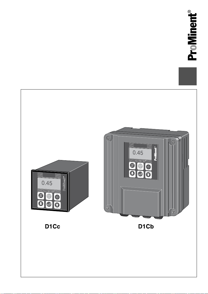
DULCOMETER® D1Cb / D1Cc
Please carefully read these operating instructions before use! · Do not discard!
The operator shall be liable for any damage caused by installation or operating errors!
Technical changes reserved.
Teile Nr. 986362 BA DM 187 09/11 EN

ProMinent Dosiertechnik GmbH
Im Schuhmachergewann 5 - 11
69123 Heidelberg
Telephone: +49 6221 842-0
Fax: +49 6221 842-419
email: info@prominent.de
Internet: www.prominent.com
986362, 4, en_GB
© 2011
2

General non-discriminatory approach
In order to make it easier to read, this
document uses the male form in grammat‐
ical structures but with an implied neutral
sense. It is aimed equally at both men and
women. We kindly ask female readers for
their understanding in this simplification of
the text.
Supplementary information
Read the following supplementary infor‐
mation in its entirety!
The following are highlighted separately in
the document:
n Enumerated lists
Instructions
Results of the instructions
ð
Supplemental instructions
Information
This provides important information
relating to the correct operation of the
system or is intended to make your
work easier.
Safety information
Safety information are provided with
detailed descriptions of the endangering
situation, see
Ä Chapter 1.1 ‘Explanation
of the safety information’ on page 8
3

Table of contents
Table of contents
1 Introduction............................................................................................................. 8
1.1 Explanation of the safety information............................................................. 8
1.2 Users' qualifications...................................................................................... 10
1.3 General Safety Information.......................................................................... 11
1.4 Correct and proper use................................................................................ 13
1.5 ID Code........................................................................................................ 14
2 Functional description........................................................................................... 17
2.1 Wall mounting/control panel installation....................................................... 18
2.2 Electrical construction.................................................................................. 19
2.2.1 Block circuit diagram................................................................................. 20
2.2.2 Galvanic Isolation ..................................................................................... 21
3 D1Cb mounting..................................................................................................... 22
3.1 Scope of supply............................................................................................ 23
3.2 Installation (Wall Mounted) .......................................................................... 24
3.3 Installation - Control Panel Mounted (Optional) .......................................... 25
3.4 Wall Mounted Installation of D1Cb (Electrical) ............................................ 27
3.4.1 Opening the device................................................................................... 28
3.4.2 Electrical Installation (Wall Mounted) ....................................................... 29
3.4.3 Electrical Installation (Control Panel Mounted) ........................................ 30
3.4.4 Installation of Coaxial Cable to Guard Terminal XE1 ............................... 31
3.4.5 Cable Cross-Sections and Cable End Sleeves......................................... 32
3.4.6 Protective RC Circuit (Optional) ............................................................... 33
3.4.7 Terminal Wiring Diagram .......................................................................... 34
3.5 Switching of inductive loads......................................................................... 38
4 D1Cc mounting..................................................................................................... 40
4.1
DULCOMETER® D1Cc scope of supply...................................................... 41
4.2
Mounting - control panel installation DULCOMETER®
4.3 Electrical Installation (Control Panel Mounted)............................................ 44
4.3.1 Installation of Coaxial Cable to Guard Terminal XE1................................ 45
4.3.2 Cable Cross-Sections and Cable End Sleeves......................................... 47
4.3.3 Terminal diagram ..................................................................................... 48
4.4 Switching of inductive loads......................................................................... 50
D1Cc....................... 41
4

Table of contents
5 Commissioning..................................................................................................... 52
5.1 Initial commissioning ................................................................................... 52
5.1.1 Selection of the Operating Language........................................................ 52
5.1.2 Selection of the Measured Variable and Measuring Range...................... 54
5.2 Activation Code for Extended Functions...................................................... 55
5.2.1 Extended Functions Obtainable with the Activation Code......................... 55
6 Operating diagram/ Display Symbols................................................................... 59
6.1 Overview of equipment/Control elements.................................................... 59
6.2 Display Symbols........................................................................................... 60
6.3 Permanent Display 1 ................................................................................... 61
6.4 Continuous display 2.................................................................................... 62
6.5 Continuous display 3.................................................................................... 62
6.6 Operating diagram........................................................................................ 64
6.7 Reduced / Complete Operating Menu ......................................................... 67
6.8 Fault Messages............................................................................................ 67
6.8.1 Fault display.............................................................................................. 67
6.9 General settings........................................................................................... 68
6.9.1 Access code.............................................................................................. 68
7 Measured Variables and Operating Menus for Amperometric Sensors............... 69
7.1 Reduced / Complete Operating Menu ......................................................... 70
7.2 Description of All Amperometric Measured Variables ................................. 70
7.3 Reduced Operating Menu ........................................................................... 71
7.4 Complete Operating Menu / Description of All Measured Variables............ 73
7.5 Calibration of All Amperometric Measured Variables .................................. 74
7.6 Calibration of the Sensor for Amperometric Measured Variables................ 75
7.6.1 Preparation for Calibration of the Sensors for Amperometric Measured
Variables .................................................................................................. 75
7.6.2 Calibration of Zero Point and Slope.......................................................... 76
7.7 Setting the Measured value.......................................................................... 79
7.8 Correcting value........................................................................................... 79
8 Measured Variables and Operating Menus for Potentiometric Sensors............... 81
8.1 Reduced / Complete Operating Menu ......................................................... 82
8.2 Description of pH, Redox and Fluoride Measured Variables ...................... 82
8.3 Reduced pH / Redox / Fluoride Operating Menu ........................................ 83
8.4 Complete Operating Menu/Description of pH / ORP / Fluoride.................... 85
8.5 Calibration of pH, ORP and Fluoride Sensors.............................................. 87
5

Table of contents
8.5.1 Description of the Calibration of pH Sensors ........................................... 88
8.5.2 Calibration of pH Sensors. Description of the Setting Ranges ................. 91
8.5.3 Calibration of pH Sensors. Description of the Error Messages ................ 91
8.5.4 Testing the Redox Sensor ........................................................................ 92
8.5.5 Description of the Calibration of Fluoride Sensors.................................... 95
8.6 Temperature correction value for pH and fluoride sensors.......................... 99
9 Measured Variables and Operating Menus for the Standard Signal General..... 101
9.1 Explanation of the Standard Signal General.............................................. 101
9.2 Changing the Measured Variable .............................................................. 103
9.3 Reduced / Complete Operating Menu ....................................................... 104
9.4 Setting the Reading ................................................................................... 104
9.5 Description of All Standard Signal Measured Values/Measured
Variables ................................................................................................... 105
9.6 Reduced Operating Menu ......................................................................... 106
9.7 Complete Operating Menu / Description of All Measured Variables ......... 108
9.8 Calibrating the Standard Signal ................................................................. 109
9.8.1 Calibration of the Zero Point of the Standard Signal General................. 110
9.8.2 Two-Point Calibration of the Standard Signal General............................ 111
10 Operating Menus Independent of Measured Variables...................................... 113
10.1 Pumps ..................................................................................................... 114
10.2 Setting the Relays.................................................................................... 116
10.2.1 Setting and Functional Description of the Relays.................................. 117
10.3 Setting the Limits...................................................................................... 122
10.4 Setting the Control.................................................................................... 125
10.5 Set mA output........................................................................................... 129
10.6 General settings....................................................................................... 131
10.6.1 Setting the Measured Variable/Measuring Range................................. 131
10.6.2 Sub-Functions of the "General Settings" Menu..................................... 132
11 Maintenance....................................................................................................... 136
11.1
Fuse replacement DULCOMETER®
11.2 Summary of Error Texts .......................................................................... 138
12 Technical data.................................................................................................... 141
12.1
Ambient conditions DULCOMETER® D1Cb / D1Cc ................................ 141
12.2 Sound Pressure Level.............................................................................. 141
12.3 Material Data............................................................................................ 142
D1Cb / D1Cc ................................. 136
6

Table of contents
12.4 Chemical Resistance................................................................................ 142
12.5 Dimensions and weights.......................................................................... 143
13 Electrical Data .................................................................................................... 144
14
Spare parts and accessories DULCOMETER® D1Cb / D1Cc............................ 148
Standards Complied With .................................................................................. 150
15
16 Disposal of Used Parts....................................................................................... 151
17 Declaration of Conformity................................................................................... 152
18 Index................................................................................................................... 154
7
Introduction
1 Introduction
These operating instructions provide infor‐
mation on the technical data and functions
DULCOMETER® controllers of the
of the
series D1Cb / D1Cc.
The controllers DULCOMETER
D1Cb and DULCOMETER® D1Cc
differ from each other only in their
type of housing and mounting loca‐
tion, not in their functionality.
1.1 Explanation of the safety information
Introduction
These operating instructions provide infor‐
mation on the technical data and functions
of the product. These operating instruc‐
tions provide detailed safety information
and are provided as clear step-by-step
instructions.
The safety information and notes are cate‐
gorised according to the following
scheme. A number of different symbols
are used to denote different situations.
The symbols shown here serve only as
examples.
®
DANGER!
Nature and source of the danger
Consequence: Fatal or very serious
injuries.
Measure to be taken to avoid this
danger
Danger!
Denotes an immediate threat‐
–
ening danger. If this is disre‐
garded, it will result in fatal or
very serious injuries.
WARNING!
Nature and source of the danger
Possible consequence: Fatal or very
serious injuries.
Measure to be taken to avoid this
danger
Warning!
Denotes a possibly hazardous sit‐
–
uation. If this is disregarded, it
could result in fatal or very
serious injuries.
8

Introduction
CAUTION!
Nature and source of the danger
Possible consequence: Slight or
minor injuries, material damage.
Measure to be taken to avoid this
danger
Caution!
Denotes a possibly hazardous sit‐
–
uation. If this is disregarded, it
could result in slight or minor inju‐
ries. May also be used as a
warning about material damage.
NOTICE!
Nature and source of the danger
Damage to the product or its sur‐
roundings
Measure to be taken to avoid this
danger
Note!
Denotes a possibly damaging sit‐
–
uation. If this is disregarded, the
product or an object in its vicinity
could be damaged.
Type of information
Hints on use and additional informa‐
tion
Source of the information, additional
measures
Information!
–
Denotes hints on use and other
useful information. It does not
indicate a hazardous or dam‐
aging situation.
9
Introduction
1.2 Users' qualifications
WARNING!
Danger of injury with inadequately qualified personnel!
The operator of the plant / device is responsible for ensuring that the qualifications
are fulfilled.
If inadequately qualified personnel work on the unit or loiter in the hazard zone of the
unit, this could result in dangers that could cause serious injuries and material
damage.
– All work on the unit should therefore only be conducted by qualified personnel.
Unqualified personnel should be kept away from the hazard zone
–
Training Definition
Instructed personnel An instructed person is deemed to be a person who has been
instructed and, if required, trained in the tasks assigned to him/
her and possible dangers that could result from improper
behaviour, as well as having been instructed in the required
protective equipment and protective measures.
Trained user A trained user is a person who fulfils the requirements made of
an instructed person and who has also received additional
training specific to the system from ProMinent or another
authorised distribution partner.
Trained qualified per‐
sonnel
A qualified employee is deemed to be a person who is able to
assess the tasks assigned to him and recognize possible haz‐
ards based on his/her training, knowledge and experience, as
well as knowledge of pertinent regulations. The assessment of
a person's technical training can also be based on several
years of work in the relevant field.
10
Training Definition
Introduction
Electrician Electricians are deemed to be people, who are able to com‐
plete work on electrical systems and recognize and avoid pos‐
sible hazards independently based on his/her technical training
and experience, as well as knowledge of pertinent standards
and regulations.
Electricians should be specifically trained for the working envi‐
ronment in which the are employed and know the relevant
standards and regulations.
Electricians must comply with the provisions of the applicable
statutory directives on accident prevention.
Customer Service
department
Customer Service department refers to service technicians,
who have received proven training and have been authorised
by ProMinent to work on the system.
Note for the system operator
The pertinent accident prevention regulations, as well as all other generally acknowl‐
edged safety regulations, must be adhered to!
1.3 General Safety Information
WARNING!
WARNING!
Live parts!
Possible consequence: Fatal or very
serious injuries
– Measure: Disconnect the mains
power supply prior to opening the
housing
De-energise damaged, defective
–
or manipulated units by discon‐
necting the mains plug
Unauthorised access!
Possible consequence: Fatal or very
serious injuries
– Measure: Ensure that there can
be no unauthorised access to the
unit
11
Introduction
WARNING!
Operating errors!
Possible consequence: Fatal or very
serious injuries
– The unit should only be operated
by adequately qualified and tech‐
nically expert personnel
Please also observe the oper‐
–
ating instructions for controllers
and fittings and any other compo‐
nent groups, such as sensors,
measuring water pumps ...
– The operator is responsible for
ensuring that personnel are quali‐
fied
CAUTION!
Electronic malfunctions
Possible consequence: Material
damage to destruction of the unit
– The mains connection cable and
data cable should not be laid
together with cables that are
prone to interference
Measure: Take appropriate inter‐
–
ference suppression measures
NOTICE!
Correct and proper use
Damage to the product or its sur‐
roundings
– The unit is not intended to
measure or regulate gaseous or
solid media
The unit may only be used in
–
accordance with the technical
details and specifications pro‐
vided in these operating instruc‐
tions and in the operating instruc‐
tions for the individual
components
NOTICE!
Correct sensor operation / Run-in
time
Damage to the product or its sur‐
roundings
– Correct measuring and dosing is
only possible if the sensor is
working perfectly
It is imperative that the run-in
–
times of the sensors are adhered
to
– The run-in times should be
allowed for when planning initial
operation
– It may take a whole working day
to run-in the sensor
– Please read the operating instruc‐
tions for the sensor
12
Introduction
NOTICE!
Correct sensor operation
Damage to the product or its sur‐
roundings
– Correct measuring and dosing is
only possible if the sensor is
working perfectly
Check and calibrate the sensor
–
regularly
NOTICE!
Compensation of control deviations
Damage to the product or its sur‐
roundings
– This controller cannot be used in
control circuits which require
rapid compensation (< 30 s)
1.4 Correct and proper use
NOTICE!
Correct and proper use
The unit is intended to measure and
regulate liquid media. The marking of
the measured variables is located on
the controller and is absolutely
binding.
The unit may only be used in accord‐
ance with the technical details and
specifications provided in this oper‐
ating manual and in the operating
manuals for the individual compo‐
nents (such as, for example, sensors,
fittings, calibration devices, metering
pumps etc.).
Any other uses or modifications are
prohibited.
NOTICE!
Compensation for control deviations
Damage to the product or its sur‐
roundings
– The controller can be used in pro‐
cesses, which require compensa‐
tion of > 30 seconds
13
Introduction
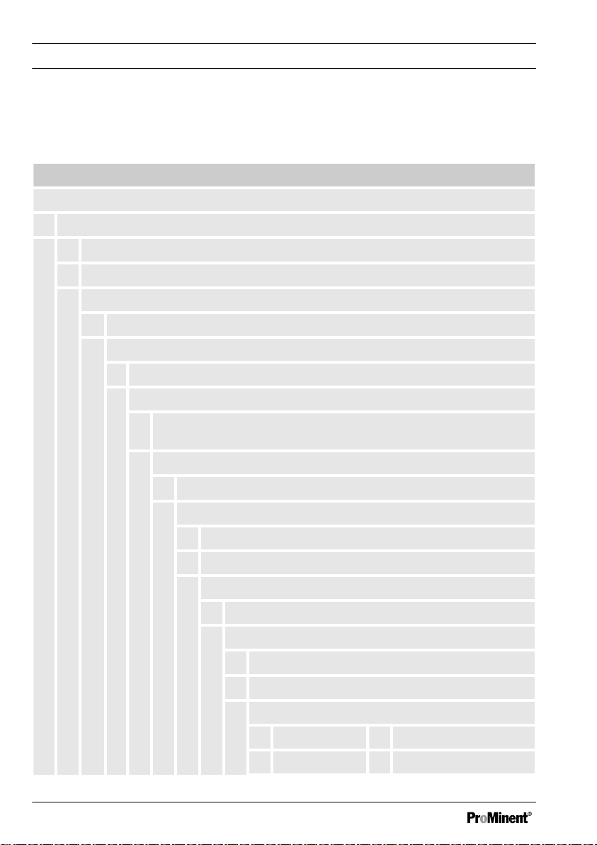
1.5 ID Code
Device identification / Identcode
DULCOMETER® controller series D1Cb / D1Cc
D1Cb / D1Cc
Type of mounting
W Wall mounted D1Cb (IP 65)
D Control panel installation D1Cc (IP54)
Version
00 with LCD and keypad / with ProMinent logo
Operating voltage
6 90...253 V, 50/60 Hz (wide voltage power unit)
Certification
01CE mark
Hardware extension I
14
0 none
Hardware extension II
0 none
1 Protective RC circuit for power relay
External connection
0 none
Software default setting
U Default setting
V Software preset
Default measured variable
0 Universal I Chlorite
A Peracetic acid P pH

DULCOMETER® controller series D1Cb / D1Cc
B Bromine R ORP
Introduction
C Chlorine S 0/4...20 mA standard
signal general
D Chlorine
X Dissolved oxygen
dioxide
F Fluoride Z Ozone
H Hydrogen per‐
L Conductivity
oxide
Connection of the measured variable
1 mA input (standard signal 0/4-20 mA, all
measured variables)
5 mV input (pH/ORP)
Correction variable
0 none
2 Temperature Pt 100/PT1000 (for
pH, conductivity, fluoride, ClO2 CDP
sensor)
4 Manual temperature input (for pH,
conductivity, fluoride, ClO2 CDP
sensor)
Control input
0 none
1 Pause
Signal output
0 none
1 Analogue signal output
0/4...20 mA
Power activation
G Alarm and 2 limit relays
15

Introduction
DULCOMETER® controller series D1Cb / D1Cc
M Alarm and 2 solenoid
valve relays
Pump activation
0 none
2 2 pumps via pulse
frequency
Control character‐
istic
0 none
1 Proportional
control
2 PID control
16

Functional description
2 Functional description
Brief functional description
The DULCOMETER® D1Cb / D1Cc 4-wire measuring transducer/controller is a device
designed to measure/control a measured variable.
In the mA measuring version, the measured variable can be changed without restrictions
in the device menu. In the mV measurement version, the menu of the
DULCOMETER®
Depending on the measured variable, sensors for pH or redox potential (ORP) or
amperometric sensors can only be connected to the measured variables in line with
Ä ‘Allocation of the measurement inputs of the DULCOMETER® D1Cb / D1Cc’ Table
on page 17
measured using a Pt 100/1000. This means that automatic temperature compensation is
possible with pH-value, conductivity and fluoride measured variables. Temperature com‐
pensation is performed in the sensor (with the exception of the chlorine dioxide sensor
type CDP) with amperometric measured variables (chlorine etc.). Operation of the
DULCOMETER® D1Cb / D1Cc takes place via the menu keys. and the data is displayed
by means of an illuminated LCD display. The LCD display ensures that the measured
value, correction variable, control value and error messages can be clearly read.
Allocation of the measurement inputs of the DULCOMETER® D1Cb / D1Cc
D1Cb / D1Cc only permits choice between pH and ORP.
. The temperature measurement serves as a correction variable and can be
Connection of the measured vari‐
able to:
Character Measured variable mV input mA input
0 no default setting
of the measured variable
X
(pH and redox can be selected)
A PES (peracetic acid) X
B Bromine X
C Chlorine X
D Chlorine dioxide X
F Fluoride X
*with measured value transducer
17

Functional description
Connection of the measured vari‐
able to:
Character Measured variable mV input mA input
H H2O2 (hydrogen peroxide) X
I Chlorite X
P pH X X*
R ORP X X*
S 0/4...20 mA standard signal general X
X O
Z O
2
3
X
X
L Conductivity X
*with measured value transducer
Description of the terminal connections for mA and mV: see Fig. 11 and Fig. 12
Description of the operating menu of the measured variables via mV connection:
see
Ä Chapter 8 ‘Measured Variables and Operating Menus for Potentiometric Sensors’
on page 81
Description of the operating menu of the measured variables via mA connection: see
Ä Chapter 7 ‘Measured Variables and Operating Menus for Amperometric Sensors’
on page 69
Description of the operating menu of the measured variables via mA standard signal: see
Ä Chapter 9 ‘Measured Variables and Operating Menus for the Standard Signal General’
on page 101
2.1 Wall mounting/control panel installation
DULCOMETER® D1Cb
The DULCOMETER®
both for wall-mounting, as well as for
installation in a control panel (with addi‐
tional control panel mounting kit).
D1Cb W is suitable
The plastic housing comprises a housing
upper section and lower section. The LCD
display and membrane keypad are
accommodated in the upper section of the
housing.
The lower section of the housing accom‐
modates the processor and power units
and any optional assemblies. A ribbon
cable connects to the LCD display and the
membrane keypad.
18

The electrical connection is made through
originally sealed, push-out cable cut-outs
on the underside of the lower section of
the housing.
A wall bracket for wall mounting is located
on the rear of the lower section of the
housing.
DULCOMETER® D1Cc
The DULCOMETER® D1Cc is suitable for
control panel installation. In this respect if
fulfils the same functions as the D1Cb.
However, the D1Cc also has an option for
upgrading with a protective RC circuit.
When correctly installed, the D1Cc has an
IP54 protection rating.
Electrical construction
2.2
The device does not have a mains switch.
It is therefore immediately ready for ope‐
ration once connected to the power
supply.
The device processes an input signal
whilst taking into consideration operator
inputs. The result is displayed and made
available to other devices via a standard
signal. When equipped with actuators, the
device can also provide control functions.
It is designed to activate metering pumps,
solenoid valves, as well as an mA
standard signal output. The activation var‐
iable is recalculated every second.
Functional description
19
externer Speicher /
EEROM/Flash
mV Eingang /
mA Eingang /
Kontakteingang
Netzteil
Temperatureingang /
Relaisausgang 3 /
Relaisausgang 2 /
Relaisausgang 1 /
Kontaktausgang 1 /
Kontaktausgang 2 /
Stromausgang /
Functional description
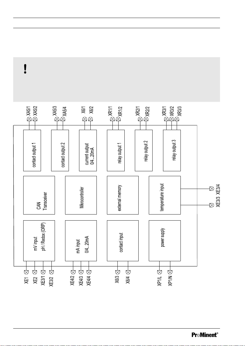
2.2.1 Block circuit diagram
NOTICE!
Connection of mV or mA sensors
The DULCOMETER® D1Cb / D1Cc is suitable for the connection of mV or mA sen‐
sors. It is not possible to connect mV and mA sensors simultaneously.
Fig. 1: Block circuit diagram
20

Netzeingang /
Netzanschluss
pH Eingang /
mA Eingang /
Kontakteingang /
Temperatureingang /
Kontaktausgang 2 /
Kontaktausgang 1 /
mA Ausgang /
Alarmausgang /
Relaisausgang 1-2 * /
Functional description
2.2.2 Galvanic Isolation
WARNING!
Protective low voltage/Mains voltage
Possible consequence: Fatal or very serious injuries
If relay 1 or 2 is operated with protective low voltage, no mains voltage may be con‐
nected to the other relay.
Fig. 2: Galvanic Isolation
* If relay 1 or 2 is operated with protective low voltage, no mains voltage many be con‐
nected to the other relay.
** No galvanic isolation between mA and mV input and temperature input.
21
D1Cb mounting
3 D1Cb mounting
n User qualification, mechanical
mounting: trained qualified personnel,
see
Ä Chapter 1.2 ‘Users' qualifica‐
tions’ on page 10
n User qualification, electrical installa‐
tion: Electrical technician, see
Ä Chapter 1.2 ‘Users' qualifications’
on page 10
NOTICE!
Mounting position and conditions
– Ensure that there is unimpeded
access for operation
Secure, low-vibration fixing
–
– Avoid direct sunlight
– Permissible ambient temperature
at fixing position: 0 ... 50 °C at
max. 95 % relative air humidity
(non-condensing)
NOTICE!
Material damage to electrostatically
sensitive components
Components can be damaged or
destroyed by electrostatic voltages.
– Before any work, on electrostati‐
cally sensitive components, dis‐
connect the power supply.
When working on electrostatically
–
sensitive components, wear an
earthed anti-static wrist band.
– Always hold components by their
corners and never touch conduc‐
tors, ICs, etc.
– Only place components on anti-
static supports or the original
packaging.
22
Ablese- und Bedienposition
–
Das Gerät in einer günstigen
Ablese- und Bedienposition
(möglichst in Augenhöhe) mon‐
tieren
Montageposition
–
Ausreichend Freiraum für die
Kabel vorsehen
–
Für die ‘Parkstellung’ des
Reglers, nach oben mindestens
120 mm Platz freihalten
3.1 Scope of supply
The following parts belong to the standard
scope of supply of a
DULCOMETER
series D1Cb controller.
Identifier Quantity
D1Cb controller 1
®
D1Cb mounting
Half screw connection, com‐
plete (set)
M12 x 1.5 threaded connec‐
tion, complete (set)
Assembly material, complete,
3P Universal (set)
Measured variable labels
D1C/D2C
Operating Manual 1
General safety notes 1
1
1
1
1
23
D1Cb mounting
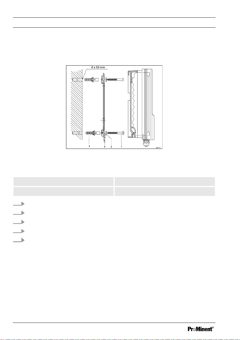
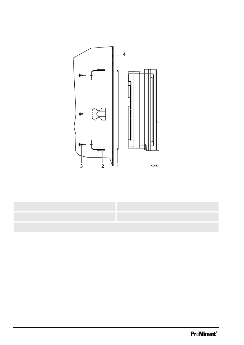
3.2 Installation (Wall Mounted)
The device can be installed directly on the wall with the aid of the wall bracket.
Fig. 3: Fixing material for wall mounting
1. 3 x Round head screws 5x45 2. 3 x Washers 5.3
3. 3 x Plastic wall plugs d8 4. Wall bracket
1. Mark the holes using the wall bracket and drill them
2. Insert wall plugs
3. Secure wall bracket in place with washers and round head screws
4. Place the device from above onto the wall bracket
5. Press the device gently against the wall bracket and slide it approx. 4 mm upwards
until you hear it engage in position
24
D1Cb mounting
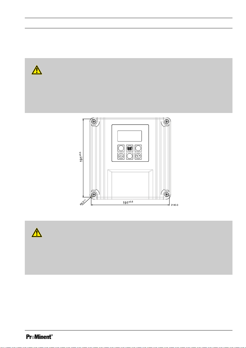
3.3 Installation - Control Panel Mounted (Optional)
CAUTION!
Dimensional variations
Possible consequence: material damage
– Photocopying the punched template can result in dimensional deviations
Use the dimensions shown in Fig. 4 and mark on the control panel
–
Fig. 4: Punched template, drawing number 3140-3 /not to scale
CAUTION!
Material thickness of control panel
Possible consequence: material damage
– The material thickness of the control panel must be at least 2 mm to ensure
secure fixing
25
D1Cb mounting
Fig. 5: The material thickness of the control panel must be at least 2 mm to ensure
secure fixing
1. 1 x Foam rubber caulk strip d3 2. 6 x Galvanised steel retaining brackets
3. 6 x Galvanised PT cutting screws 4. Control panel
For the part number of the assembly set, refer to
26
Ä Table on page 149
D1Cb mounting
1. Using the dimensions shown in
Fig. 4 mark the precise position of the device on
the control panel
2. Mark the corner points and drill (drill diameter 12 - 13 mm)
3. With a punching tool or jigsaw make the opening as per the punched template
drawing
4. Chamfer the cut edges and check whether the sealing surfaces are smooth for the
caulk strip
Otherwise the seal cannot be guaranteed
ð
5. Press the caulk strip evenly into the groove running around the device
6. Place the device into the control panel and fix in place at the rear by means of the
retaining brackets and PT cutting screws
The device should project approx. 35 mm from the control panel
ð
3.4 Wall Mounted Installation of
D1Cb (Electrical)
WARNING!
Electrical voltage
Possible consequence: Fatal or very
serious injuries
– The electrical connection to the
device should only be made once
it has been fitted to the wall or
control panel
The device must be electrically
–
disconnected before it is opened
– Ensure that the device cannot be
reconnected accidentally
NOTICE!
Opening the device
Damage to the product or its sur‐
roundings
– The device may only be opened
by qualified personnel
The device should only be
–
opened when fitted to the wall or
control panel
27
D1Cb mounting
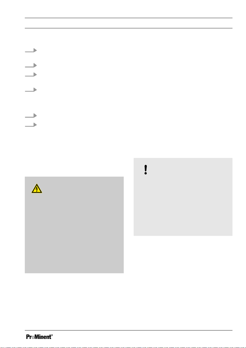
3.4.1 Opening the device
Fig. 6: Opening the device
1. Loosen the 4 captive screws (1).
2. Lift the upper section of the device from the lower section (2). A wide flathead
screwdriver may be of assistance.
3. Insert the upper section with both guide rails into the lower section (3 and 4)
(parked position)
28
A0014
D1Cb mounting
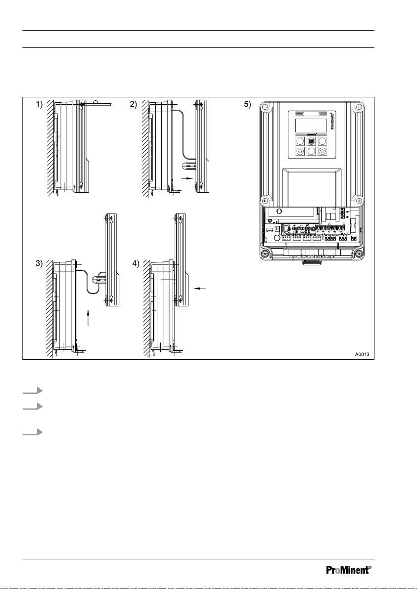
3.4.2 Electrical Installation (Wall Mounted)
NOTICE!
Threaded holes
Using a suitable tool, punch out the
threaded holes according to the
number of cables ( Æ approx. 4 mm).
– Punch aids are provided to punch
out the threaded holes
1. Remove cable sheathing over a
sufficient length
2. Fit screw connection (1), pressure
ring (2) and seal (3) onto cable
3. Insert cable and fittings into the
threaded hole
4. Align the cable and push in until
enough cable is in the control
housing
5. Screw in screw connection and
tighten firmly
6. Shorten cable wires to the precise
overall length and strip off approx. 8
mm insulation
7. Fit cable end sleeves to the wires.
Refer to
Ä on page 32
8. Connect up the wires to the termi‐
nals according to the electrical
wiring diagram Fig. 11
Punched out threaded holes can be
resealed with the M20 dummy washers
(4) provided.
The M12 x 1.5 screw connections and
brass lock nuts are used for the 4 open‐
ings in the front row.
Fig. 7: Punching out the threaded holes
1. Screw connec‐
tion M20 x 1.5
3. Pressure ring
M20
2. Pressure ring
M20
4. Dummy washer
M20
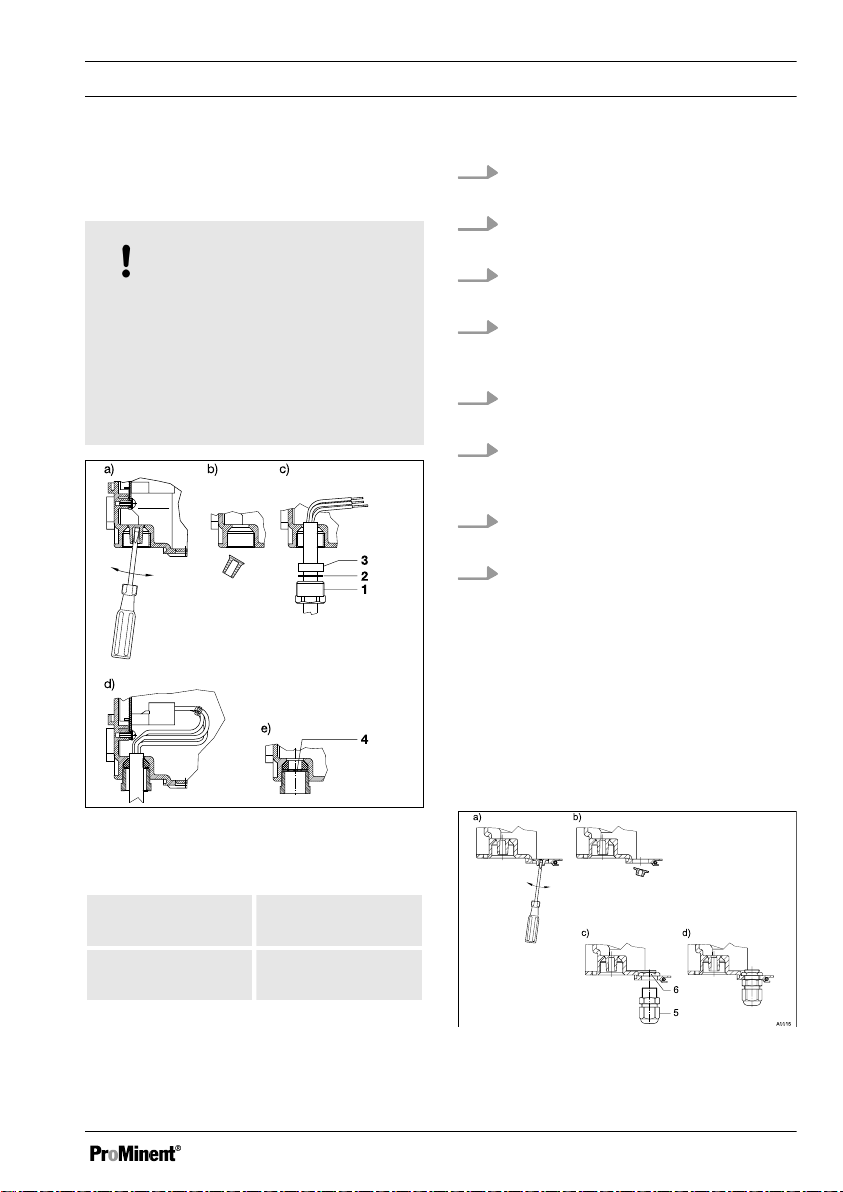
Fig. 8: M12x1.5 screw connections
29

D1Cb mounting
5. Screw connec‐
tion M12 x 1.5
6. Lock nut
M12x1.5
1. Fit lock nut M12x1.5 (6) on the
inside
2. Fit screw connection M12x1.5 (5)
from the outside and tighten firmly
3.4.3
Electrical Installation (Control Panel Mounted)
Proceed as described under "Electrical
Installation (Wall Mounted)". Refer to
Ä Chapter 3.4.2 ‘ Electrical Installation
(Wall Mounted) ’ on page 29
Only the rear row of threaded holes
(M20x1.5) should be used when the
device is mounted in a control panel. The
front row (M12x1.5) lies outside of the
control panel.
Connect up as per the electrical terminal
wiring diagram. Refer to
Ä Chapter 3.4.7
‘Terminal Wiring Diagram ’ on page 34
30
 Loading...