

ProMinent DULCOMETER D1C A D Series, DULCOMETER D1C A W Series Operating Instructions Manual
Page 1
Operating Instructions
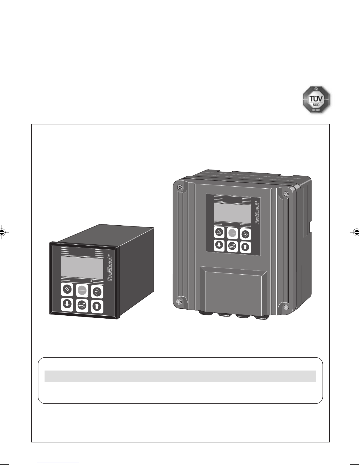
DULCOMETER® D1C
Part 2: Adjustment and Operation,
Measured Variable Redox/ORP
®
ProMinent
D1C2-001-D
Redox/ORP
STOP
START
mV
750
DULCOMETER
Redox/ORP
750
DULCOMETER
STOP
START
Type WType D
mV
D1C A
___ ___ ___ ___ ___ ___ ___ ___ ___ ___ ___ ___ ___
Please enter the identity code of your device here.
Please completely read through operating instructions! · Do not discard!
The operator shall be liable for any damage caused
Part No. 987850 ProMinent Dosiertechnik GmbH · 69123 Heidelberg · Germany BA DM 183 10/10 EN
by installation or operating errors!
Page 2

1 Device Identification / Identity Code
D1C A DULCOMETER® Controller Series D1C / Version A
Type of mounting
D Control panel installation 96 x 96 mm
W Wall mounting
Operating voltage
0 230 V 50/60 Hz
1 115 V 50/60 Hz
2 200 V 50/60 Hz (only with type of mounting D)
3 100 V 50/60 Hz (only with type of mounting D)
4 24 V AC/DC
Measured variable
R Redox/ORP (-1000...+1000 mV)
Connection of measured variable
1 Terminal, standard signal 0/4-20 mA
2 SN6 connector
5 Terminal mV
Correction variable
0 None
Feed forward control
0 None
1 via standard signal 0/4-20 mA
2 via frequency 0-500 Hz
3 via frequency 0-10 Hz
Control input
0 None
1 Pause
Signal output
0 None
1 standard signal 0/4-20 mA measured value
2 standard signal 0/4-20 mA control variable
42 standard signal outputs 0/4-20 mA, freely programmable
Power control
G Alarm and 2 limit value/timer relays
M Alarm and 2 solenoid valve relays
R Alarm relay and servomotor with feedback
0 None
2 Two pumps
Pump control
Control characteristics
0 None
1 Proportional control
2 PID control
Log output
0 None
Language
D German
E English
F French
I Italian
N Dutch
S Spanish
PPolish
ASwedish
B Portuguese
U Hungarian
J Japanese
G Czech
D1C A
Please enter the identity code of your device here!
2
Page 3
2 General User Information
Page
1 Device Identification / Identity Code ....................................................................................................... 2
2 General User Information ......................................................................................................................... 3
3 Device Overview / Controls ..................................................................................................................... 4
4 Functional Description ............................................................................................................................. 5
5 Display Symbols ...................................................................................................................................... 6
6 Operation ................................................................................................................................................. 7
7 Restricted Operating Menu ..................................................................................................................... 8
Layout .............................................................................................................................................. 8
Description ...................................................................................................................................... 9
8 Complete Operating Menu .................................................................................................................... 12
Overview ........................................................................................................................................ 12
Description .................................................................................................................................... 13
9 Fault / Remarks / Troubleshooting ........................................................................................................ 24
General User Information
These operating instructions describe the technical data and function of the series DULCOMETER® D1C
controller, provide detailed safety information and are divided into clear steps.
IMPORTANT
• Please observe the parts of these operating instructions applicable to your particular
version! This is indicated in the Section “Device Identification / Identity Code”.
• Correct measuring and dosing is only possible in the case of impeccable operation of the
probe. The probe has to be calibrated / checked regularly!
NOTE
A form “Documentation of controller settings type D1C” is available under
www.prominent.com/documentation_D1C for the purpose of documenting the controller
settings.
3
Page 4

3 Device Overview / Controls
"Change"
Button
"Branch back"
Button
"Down"
Button
Redox/ORP
STOP
START
Display field
Measured variable
Redox/ORP
Graphic
display
®
"Start/stop"
Button
"Enter"
Button
"Up"
Button
STOP
START
CHANGE button
To change over within a menu level
and to change from one variable to
another within a menu point.
START/STOP button
Start/stop of control and metering
function.
ENTER button
To accept, confirm or save a displayed
value or status. For alarm acknowledgement.
D1C2-002-GB
UP button
To increase a displayed numerical value
and to change variables (flashing
display)
BRANCH BACK button
Back to permanent display or to start
of relevant setting menu.
DOWN button
To decrease a displayed numerical
value and to change variables (flashing
display).
4
Page 5

4 Functional Description
NOTE
Please refer to the description of the complete operating menu in Section 8 for a detailed
description of the individual characteristics of the DULCOMETER® D1C controller!
4.1 Operating Menu
The D1C controller permits settings to be made in two different menus. All values are preset and can be
changed in the complete operating menu.
The controller is delivered with a restricted operating menu so that the D1C controller can be used
effectively in many applications from the very onset. If adaptations prove to be necessary, all relevant
parameters can then be accessed by switching over to the complete operating menu (see “General
Settings”).
4.2 Access Code
Access to the setting menu can be prevented by setting up an access code. The D1C controller is supplied
with the access code 5000 which permits free access to the setting menu. The calibration menu remains
freely accessible even if access to the setting menu is blocked by the code.
4.3 Control
The D1C can operate as a proportional controller or as a PID controller - depending on the device version
(see identity code) and the setting.
The controlled variable is recalculated once a second. Control procedures which require rapid correction of
setpoint deviations (less than approx. 30 seconds) cannot be processed with this controller. The cycle
times must be taken into consideration when activating solenoid valves (pulse length) in the same way as
their running times when activating servomotors (3-point).
Via the control input pause, the control function (selection of controlled variable) can be switched off. The
calculation of the controlled variable starts again after cessation of "pause".
4.4 Feed Forward Control
The D1C controller can process a signal of a feed forward control. Depending on the device version (see
identity code) and the setting, this signal can be obtained in any form of a 0–20 mA or 4–20 mA signal or as
a digital contact signal with the maximum frequencies 10 Hz or 500 Hz.
This signal can be used, for example, for flow-proportional metering (multiplicative effect) or feed forwarddependent basic load metering (additive effect). The result of control variable calculation from the
proportional or PID control is multiplied by or added to the feed forward signal. A multiplicative feed forward
variable at the level of the set rated value carries over the calculated controlled variable unchanged into the
control variable:
Control variable = Feed forward variable/rated value x calculated controlled variable
During start-up, the zero point has to be checked. The feed forward control is not designed for switching off
permanently the actuating variable (signal ≈ 0).
An additive feed forward variable at the level of the rated value results in maximum control variable:
Control variable (max. 100 %) = (Feed forward variable/rated value x
max. control variable) + calculated controlled variable
4.5 Error Messages
Error messages and information are indicated on the bottom line in the permanent display 1. Errors to be
acknowledged (acknowledgement switches off the alarm relay) are indicated by the "
which still apply after acknowledgement are indicated alternately. During correction variable processing
(temperature for correction of pH-value), the value is indicated in the same line as the error/note. Faults
which are rectified of their own accord due to changed operating situations are removed from the
permanent display without the need for acknowledgement.
". Errors/notes
5
Page 6

5 Display Symbols
The display of the DULCOMETER® D1C controller uses the following symbols:
Description Comment Symbol
Limit value transgression Symbol
Relay 1, upper left
Symbol
Relay 1, lower left
Symbol
Relay 2, upper right
Symbol
Relay 2, lower right
Metering pump 1 (oxidant) Symbol
Control off left
Symbol
Control on left
Metering pump 2 (reducing agent) Symbol
Control off right
Symbol
Control on right
Solenoid valve 1 (oxidant) Symbol
Control off left
Symbol
Control on left
Solenoid valve 2 (reducing agent) Symbol
Control off right
Symbol
Control on right
Servomotor
Control, open relay
Control, close relay
Without control
Thickness of bar
Position feedback increases from left to right
during opening
Stop button pressed
Manual metering
Fault
6
Page 7

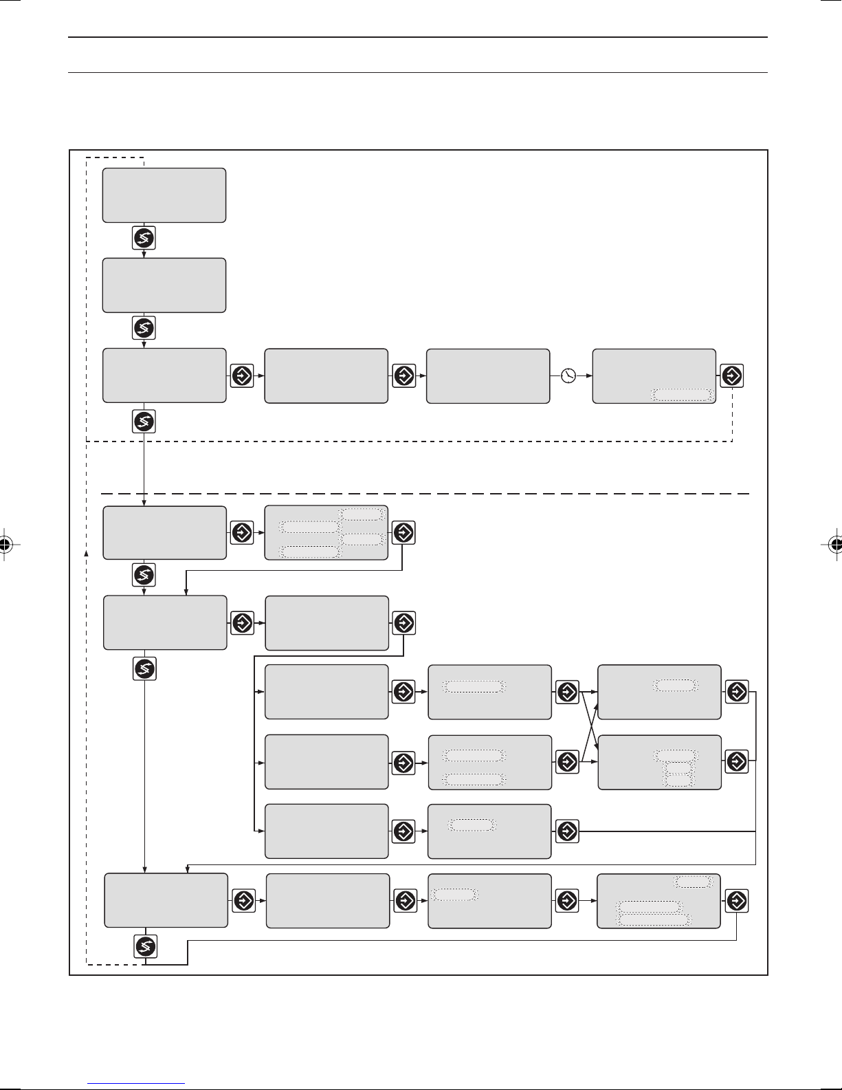
6 Operation
Permanent
display 1
Permanent
display 2
Calibration
menu
Various
Setting menus
Access code
The various menus are selected with
the CHANGE button
The menu is started with
the ENTER button
BRANCH BACK to permanent display
or to relevant setting menu
Calibration notes
Access code, correct
Parameter
setting
D1C2-007-GB
NOTE
Access to the setting menus can be barred with the access code!
The number and scope of setting menus is dependent on the device version!
If the access code is selected correctly in a setting menu, then the following setting menus are
also accessible!
If within a period of 10 minutes no button is pushed, the unit automatically branches back from the
calibrating menu or a setting menu to the permanent display 1.
BRANCH BACK without
saving setting
BRANCH BACK to
start of setting
Variables flash
Text 1
Selection 1
Text 2
Selection 2
Text 1
Selection 1
Text 2
Selection 2
CHANGE from selection to selection
Change numbers or
settings of selection
ENTER and save setting,
continue to next menu
D1C2-008-GB
7
Page 8
7 Restricted Operating Menu / Layout
The restricted operating menu permits simple operation of the most important parameters. The following
overview shows the settings which can be selected.
mV
750
mea. val.
fd. fwd.:
reg. val.:
w: 750 mV
check probe
ORP
limits
setting ?
750 mV
70 %
59 %
Permanent display 1
Permanent display 2
only with control
(w = setpoint)
check probe
ORP
probe in buffer
460 mV
limit 2
900 mV
limit 1
100 mV
upper
lower
Positive values of setting variable:
Negative values of setting variable:
check probe
measurement act.
please wait !
460 mV
check probe
ORP
value:
buffer:
Number and scope of setting menus
is dependent on the device.
Access to setting menus can
be blocked with access code.
Oxidant agent
Reducing agent
460 mV
465 mV
control
settings ?
Setting in
complete
operating
menu
general setting
information
Only with control
control
regulated value:
positive oxide
negative reduc
control
normal
current regulat.
value: 30 %
or
control
with dead zone
current regulat.
value: 30 %
or
control
manual
current regulat.
value: 30 %
ident-code: D1CA
DxRxxxxxxxxxx
Software version
D1C-A1 FW-5.00
For normal control
setpoint
750 mV
Control with dead zone
setpoint 2 upper
750 mV
setpoint 1 lower
650 mV
Proportional control
ctrl. parameter
xp =
PID control
ctrl. parameter
xp =
Ti =
Td =
For manual control
manual dosing
15 %
regulated range
alarm relay access c.:
active
operating menu:
english
=
=
restricted
10 %
10 %
0 s
0 s
5000
D1C2-010-Redox-GB
8
Page 9

Restricted Operating Menu / Description
mV
Permanent display 1
750
mea. val.
fd. fwd.:
reg. val.:
w: 750 mV
750 mV
70 %
59 %
Permanent display 2
only with control
(w = setpoint)
Checking the Redox Probe
During calibration, the D1C sets the command outputs to “0”. Exception: if a basic load or a manual control
variable was set, these are maintained during calibration. The standard signal outputs mA (measuring value
or correction value) are frozen. The measured value or the standard buffer value 220 mV or 465 mV is
proposed as the buffer value; this value is adjustable (arrow keys). After everything has been checked, all
error tests which refer to the measured value are restarted.
check probe
ORP
check probe
ORP
probe in buffer
460 mV
Positive values of setting variable:
Negative values of setting variable:
check probe
measurement act.
please wait !
460 mV
check probe
ORP
value:
buffer:
Oxidant agent
Reducing agent
D1C2-011-Redox-GB
460 mV
465 mV
= automatic timing
Permanent display 1
Possible values
Initial value Increment Lower value Upper value Remarks
Buffer values Measured valve 1 mV -2000 mV +2000 mV
185–265 mV 220 mV
425–505 mV 465 mV
Error message Condition Effect
Measured value high Measured value Return to permanent display:
40 mV > buffer Basic metering load
Measured value low Measured value "
40 mV < buffer
D1C2-012-Redox-GB
9
Page 10

Restricted Operating Menu / Description
Limits
Access to all setting menus can be blocked with an access code !
limits
setting ?
limit 2
900 mV
limit 1
100 mV
upper
lower
D1C2-014-GB
Possible values
Initial value Increment Lower value Upper value Remarks
Type of limit trans- upper Limit transgression
gression Limit 1: lower lower when exceeding or
Limit 2: upper off* dropping below value
*only with limit relay
Limit value Limit 1: 500 mV 1 mV -2000 mV 2000 mV
Limit 2: 1000 mV 1 mV -2000 mV 2000 mV
Control
Access to all setting menus can be blocked with an access code !
Note: The controlled variable is recalculated every second. Only
suitable for processes with time constants greater than 30 s !
control
settings ?
Only with control
Setting in
complete
operating
menu
control
regulated value:
positive oxide
negative reduc
control
normal
current regulat.
value: 30 %
or
control
with dead zone
current regulat.
value: 30 %
or
control
manual
current regulat.
value: 30 %
Positive values of setting variable:
Negative values of setting variable:
For normal control
setpoint
750 mV
Control with dead zone
setpoint 2 upper
750 mV
setpoint 1 lower
650 mV
Proportional control
ctrl. parameter
xp =
PID control
ctrl. parameter
xp =
Ti =
Td =
For manual control
manual dosing
15 %
regulated range
Oxidant agent
Reducing agent
10 %
10 %
0 s
0 s
D1C2-015-Redox-GB
10
Page 11

Restricted Operating Menu / Description
Possible values
Initial value Increment Lower value Upper value Remarks
Setpoint 750 mV 1 mV lower limit upper limit 2 setpoints necessary
measuring range measuring range for control with dead zone.
Setpoint 2 > setpoint 1
Control parameter xp 10 % 1 % 1 % 500 % xp referred to measuring range
Control parameter Ti off 1 s 1 s 9999 s Function off = 0 s
Control parameter Td off 1 s 1 s 2500 s Function off = 0 s
Manual metering 0 % 1 % -100 % +100 %
Abbreviations for control variables:
x
= 100 %/Kp (inverse proportional coefficient)
p
Ti=I controller integration time [s]
Td=D controller differential time [s]
General Settings
Access to all setting menus can be blocked with an access code !
general setting
information
Initial value Increment Lower value Upper value Remarks
Alarm relay active active
Access code 5000 1 1 9999
Language as per identity as per identity
Operating menu restricted restricted
ident-code: D1CA
DxRxxxxxxxxxx
software version
D1C-A1 FW-5.00
Possible values
not active
code code
complete
alarm relay access c.:
active
operating menu:
english
=
=
restricted
5000
D1C2-016-GB
Access Code
Access to the setting menu can be prevented by setting up an access code. The DULCOMETER
controller is supplied with the access code 5000 which permits free access to the setting menu. The
calibration menu remains freely accessible even if access to the setting menu is blocked by the code.
®
D1C
11
Page 12

8 Complete Operating Menu / Overview
All parameters of the controller can be set in the complete operating menu (access see previous page). The
following overview shows the settings which can be selected:
mV
750
mea val.
fd. fwd.:
reg. val.:
w: 750 mV
check probe
ORP
meas. value
setting ?
pumps
setting ?
750 mV
70 %
59 %
Permanent display 1
Permanent display 2
only with control
(w = setpoint)
Number and scope of setting menus
is dependent on the device.
Access to setting menus can
be blocked with access code.
Only with pumps
relays
setting ?
limits
setting ?
servomotor
setting ?
control
setting ?
feed forward ctrl.
setting ?
Only with limit relay,
solenoid valve relay
or servomotor
Only with
servomotor
Only with control
Only with feed
forward control
signal output 1
mA setting ?
signal output 2
mA setting ?
general setting
information
Only with standard
signal output
Only with 2 standard
signal outputs
12
D1C2-017-Redox-GB
Page 13

Complete Operating Menu / Description
mV
Permanent display 1
750
mea. val.
fd. fwd.:
reg. val.:
w: 750 mV
750 mV
70 %
59 %
Permanent display 2
only with control
(w = setpoint)
Checking the Redox Probe
During calibration, the D1C sets the command outputs to “0”. Exception: if a basic load or a manual control
variable was set, these are maintained during calibration. The standard signal outputs mA (measuring value
or correction value) are frozen. The measured value or the standard buffer value 220 mV or 465 mV is
proposed as the buffer value; this value is adjustable (arrow keys). After everything has been checked, all
error tests which refer to the measured value are restarted.
check probe
ORP
check probe
ORP
probe in buffer
460 mV
Positive values of setting variable:
Negative values of setting variable:
check probe
measurement act.
please wait !
460 mV
check probe
ORP
value:
buffer:
Oxidant agent
Reducing agent
D1C2-018-Redox-GB
460 mV
465 mV
= automatic timing
Permanent display 1
D1C2-019-Redox-GB
Possible values
Initial value Increment Lower value Upper value Identification code expression
Buffer values Measured value 1 mV -2000 mV +2000 mV if measured variables 2 and 5
185–265 mV 220 mV are connected
425–505 mV 465 mV – +1000 mV if measured variable 1 is connected
Error message Condition Effect
Measured value high Measured value Return to permanent display:
40 mV > buffer Basic metering load
Measured value low Measured value Return to permanent display:
40 mV < buffer Basic metering load
13
Page 14

Complete Operating Menu / Description
Measured Value
Access to all setting menus can be blocked with an access code !
Standard signal input mA
meas. value
range adjustment
meas. value
setting ?
4 mA
= 0 mV
meas. value
checkout time
measured value
off
IMPORTANT
When changing the range adjustment, the adjustments in all menus have to be checked!
Possible values
Initial value Increment Lower value Upper value Remarks
meas. value
range adjustment
20 mA =
1000 mV
D1C2-020-Redox-GB
Standard signal input 4 mA 0 mA
lower signal limit 4 mA
Allocated 0–1 V 1 mV -2000 mV +2000 mV
probe voltage
Checkout time off 1 s 1 s 9999 s Constant measurement
signal results in message
and alarm.
Function off = 0 s
Control Time Measuring Value
IMPORTANT
This function may not be activated for applications where it can be assumed that the
measuring value does not change.
This function checks whether the measuring value from the sensor (measuring value input) changes within
the “control time measuring value”. It is assumed that the value does not change for an intact sensor.
If the measuring value does not change during this control time, the DULCOMETER
®
D1C sets the control
output to “0” and the alarm relay drops out. The LCD display shows e.g. the message “check mV-probe”.
14
Page 15

Complete Operating Menu / Description
Correction Value*
Access to all setting menus can be blocked with an access code !
correction value
setting ?
correction value
temperature
automatic
*In the setting menu “correction value” for this equipment enables you to display the temperature or to
maintain an mA signal proprotional to the temperature. No temperature adjustment is made to the
measured variable!
Pumps
Access to all setting menus can be blocked with an access code !
Only with pumps for control
pumps
setting ?
control ORP
pump1 oxide
pump2 reduc
dosing pump max.
pump1:
pump2:
180
180
pulse/minute
D1C2-022-Redox-GB
Possible values
Initial value Increment Lower value Upper value Remarks
Max. stroke/minute of 180 1 1 500 off = 0 strokes/min
pumps 1 and 2
Relay for power control
Access to all setting menus can be blocked with an access code !
Only with limit relay, solenoid valve relay or servomotor
relays
setting ?
relay adjustment
relay1:
relay2:
SV1
SV2
solenoid valve 1
oxide
period
min. time
10 s
1 s
solenoid valve 2
reduc
period
min. time
10 s
1 s
D1C2-023-Redox-GB
15
Page 16

Complete Operating Menu / Description
with timer
relays
setting ?
relay adjustment
relay1: timer
relay2: timer
control timer 1
relay 1
period 1 h
t on: 1 min
control timer 2
relay 2
period 1 h
t on: 1 min
D1C2-033-Redox-GB
Possible values
Initial value Increment Lower value Upper value Remarks
Relay adjustment as per
identity code
Relay 1 Solenoid valve 1
Limit value 1* *For “limit value”, the relays
Actuator 1 remain active, even in the
Timer 1 event of a fault.
Servomotor only with servomotor
off
Relay 2 Solenoid valve 2
Limit value 2*
Actuator 2
Timer 2
off
Cycle 10 s 1 s 10 s 9999 s for solenoid valve
min. time 1 s 1 s 1 s Cycle/2 for solenoid valve
Set here the smallest
permitted operating factor
of the connected device.
Period (Cycle) off 1 h 1 h / off 240 h for timer
t on 1 min 1 min 1 min 60 min for timer
NOTE
The limit value relay can be defined in such a way as to respond as an actuator, i.e. if a limit
value relay closes a circuit, it opens when a pause contact is activated and/or for a
subsequent delay period td (if td is set to > 0 min in “General settings”).
Cycle
t
Timer relay
on
off
on
IMPORTANT
The timer will be reset if there is a drop in the power supply.
16
t
Page 17

Complete Operating Menu / Description
At the end of the (timer) cycle time, the DULCOMETER® D1C closes the assigned relay for the duration of
“t on” (timer). “Pause” interrupts the timer.
When the clock is shown in the LC display, the timer can be reset to the start of the cycle at precisely this
point using the Enter button.
The % figure in the LC display indicates the progress of the current cycle.
Timer relays may be used, e.g. for shock metering or sensor cleaning.
Cycle
Solenoid
valve
on
off
on
off
The switching time of the DULCOMETER® D1C (solenoid valve) depends on the actuating variable and the
“min. time” (smallest permitted operating factor of the connected device).
The actuating variable determines the ratio ton/cycle and thus the switching times (see fig. above).
The “min. time” influences the switching times in two situations:
a) theoretical switching time < min. time:
Cycle
min. time
on
off
Cycle
on
off
t
on
t
on
Cycle
Cycle
Cycle
Cycle
Cycle
min. time
min. time
Control
variable: 80 %
t
on
Cycle
t
Control
variable: 50 %
t
on
Cycle
t
theoretical
t
actual
t
= 0.80
= 0.50
The DULCOMETER® D1C does not switch for a certain number of cycles until the sum of the theoretical
switching times exceeds the “min. time”. Then the
total time
.
b) theoretical switching time > (cycle - min. time) and calculated switching time < cycle
Cycle
min. time
on
off
Cycle
on
off
The DULCOMETER® D1C does not deactivate for a certain number of cycles until the differences between
cycle and theoretical switching time exceed the “min. time”.
Cycle
Cycle
DULCOMETER® D1C
Cycle
Cycle
min. time
t
t
switches for the duration of this
theoretical
actual
17
Page 18

Complete Operating Menu / Description
Limits
Access to all setting menus can be blocked with an access code !
limits
setting ?
limit 2 upper
800 mV
limit 1 lower
100 mV
relay 1 LV 1
- active closed
∆t on 0 s
∆t off 0 s
hysteresis
limits: 10 mV
∆t on: off
control: on
relay 2 LV2
- active closed
∆t on 0 s
∆t off 0 s
D1C2-024-Redox-GB
Possible values
Initial value Increment Lower value Upper value Remarks
Type of limit transgression upper Limit transgression when
Limit 1: lower lower exceeding or dropping below value
Limit 2: upper off* *only with limit relay
Limit value Limit 1: 500 mV 1 mV -2000 mV 2000 mV
Limit 2: 1000 mV 1 mV -2000 mV 2000 mV
Hysteresis limits 10 mV 1 mV 10 mV 2000 mV Effective in direction of cancelling
limit transgression
Checkout time limits off 1 s 1 s 9999 s Results in message and alarm.
off = 0 s:
Function switched off,
no message, no alarm
Control on on
off
Actuating direction active closed active closed Reacts as make contact
limit value 1; active open Reacts as break contact
limit value 2
Switch-on delay ∆t on 0 s 1 s 0 s 9999 s
Switch-off delay ∆t off 0 s 1 s 0 s 9999 s
If the limit is exceeded for longer than the “Delay time - limit values”, an error message is given which
must be acknowledged, and the alarm relay circuit is broken. If “Control” is also set to “off” the control
process stops.
18
Page 19

Complete Operating Menu / Description
Servomotor
The operating range is defined by the total resistance range of the feedback potentiometer. The maximum
limit of the range actually used is set by defining the control range.
IMPORTANT
• To ensure correct operation, the activation time of the actuator used should not be less
than 25 seconds for the control range from 0…100 %!
• Activation of the servomotor must be carried out with the same meticulous care as taken
when calibrating a measuring probe.
Access to all setting menus can be blocked with an access code !
Only with servomotor
servomotor
setting ?
servomotor
setting
current position:
servomotor
open ?
servomotor
open
please wait !
servomotor
opened !
value take over ?
servomotor
OK
current position:
servomotor
close ?
dosing:
control range:
0 % to
operating range
oxide
100 %
servomotor
close
please wait !
servomotor
closed !
value take over ?
= automatic timing
D1C2-025-Redox-GB
Possible value
Initial value Increment Lower value Upper value Remarks
Servomotor Setting Setting
ok
off
Control direction Oxidant Oxidant
Reducing
Control range 100 % 1 % 10 % 100 % in % of operating range
NOTE
• If the broad bar is to the far right, the servomotor is fully open.
• The continuous display shows the degree (in %) to which it is open (the greater the percentage,
the more open the servomotor).
19
Page 20

Complete Operating Menu / Description
Control
Access to all setting menus can be blocked with an access code !
Note: The controlled variable is recalculated every second. Only
suitable for process with time constants greater than 30 s !
control
settings ?
Only with control
control
regulated value:
positive oxide
negative reduc
control
normal
current regulat.
value: 30 %
Positive values of setting variable:
Negative values of setting variable:
For normal control
setpoint
750 mV
Control with dead zone
setpoint 2 upper
750 mV
setpoint 1 lower
650 mV
For manual control
manual dosing
15 %
regulated range
Oxidant agent
Reducing agent
Proportional control
ctrl. parameter
xp =
10 %
PID control
ctrl. parameter
xp =
Ti =
Td =
control load:
regulated range
10 %
0 s
0 s
10 %
D1C2-026-Redox-GB
Possible values
Initial value Increment Lower value Upper value Remarks
Control normal normal When controlling with dead zone,
with dead zone the feed forward control is not used
manual for measured values within
the dead zone.
2 setpoints necessary for
Lower limit Upper limit control with dead zone.
Setpoint 750 mV 1 mV measuring range measuring range Setpoint 2 > setpoint 1
Control parameter xp 10 % 1 % 1 % 500 % xp referred to measuring range
Control parameter Ti off 1 s 1 s 9999 s Function off= 0 s
Control parameter Td off 1 s 1 s 2500 s Function off = 0 s
Additive basic load 0 % 1 % -100 % +100 %
Manual metering 0 % 1 % -100 % +100 %
Abbreviations for control variables:
x
: 100 %/Kp (inverse proportional coeffizient)
p
: Integration time of I-controller [s]
T
i
: Differential time of D-controller [s]
T
d
20
Page 21

Complete Operating Menu / Description
Feed Forward Control
feed forward ctrl.
setting ?
feed forward ctrl.
Hz / mA
10 Hz
feed forward ctrl.
rated value:
10.00 Hz
feed forward ctrl.
disturb. variable:
additive
feed forward ctrl.
max. additive
regulated value:
100 %
D1C2-029-Redox-GB
Possible values
Initial value Increment Lower value Upper value Remarks
Feed forward control as per identitiy None Signal processing:
(Flow) code 10 Hz Signal <0.02 Hz = no flow
500 Hz Signal <0.2 Hz = no flow
Standard signal: 0…20 mA Signal <0.2 mA = no flow
4–20 mA 4…20 mA Signal <4.2 mA = no flow
Feed forward control 10 Hz 0.01 Hz 0.1 Hz 10 Hz Depending on signal type.
rated value 500 Hz 1 Hz 5 Hz 500 Hz Maximum limitation
20 mA 0.1 mA 0/4 mA 20 mA of range used.
Feed forward
control multiplicative multiplicative
Feed forward
control effect additive
Max. add. regulated only with add. feed
variable 100 % 1 % -500 % +500 % forward control
Standard Signal Output 1
Access to all setting menus can be blocked with an access code !
Only with standard signal output
signal output 1
mA setting ?
signal output 1
mA
measured value
0…20 mA
Control with standard signal
control
regulated value:
positive oxide
negative reduc
signal output 1
measured value
0 mA =
20 mA =
0 mV
1000 mV
signal output 1
regulated value
0 mA =
20 mA =
0%
100%
D1C2-027-Redox-GB
21
Page 22

Complete Operating Menu / Description
Standard Signal Output 2
Access to all setting menus can be blocked with an access code !
Control with standard signal
control
regulated value:
positive oxide
negative reduc
signal output 2
measured value
0 mA =
20 mA =
0 mV
1000 mV
signal output 2
mA setting ?
Only with 2 standard signal outputs
signal output 2
mA
measured value
0…20 mA
Possible values
Initial value Increment Lower value Upper value Remarks
Variable allocation as per identity Measured value
code Controlled variable If control applicable
Output range 0…20 mA 0…20 mA
4…20 mA
3.6/4-20 mA Reduction to 3.6 mA
Range measured
value 0–1 V 1 mV -2000 mV 2000 mV Minimum range 10 mV
Range controlled
variable 0 %…+100 % 1 % -100 % +100 % Minimum range 1 % of
signal output 2
regulated value
0 mA =
20 mA =
0%
100%
D1C2-030-Redox-GB
when alarm relay switches
(not limit value violation)
measured value
General Setting
Access to all setting menus can be blocked with an access code !
general setting
information
22
ident-code: D1CA
DxRxxxxxxxxxx
software version
D1C-A1 FW-5.00
alarm relay
active
pause normal
- active... closed
- alarm off
- td: 0 min
access c.:
operating menu:
english
=
=
complete
5000
D1C2-028-GB
Page 23

Complete Operating Menu / Description
Possible values
Initial value Increment Lower value Upper value Remarks
Alarm relay active active
not active
Pause normal normal
Hold
Control input pause active closed active closed Reacts as make contact
active open Reacts as break contact
Pause with alarm off off Alarm relay can be
on triggered by pause contact
td 0 min 1 min 0 min 60 min
Access code 5000 1 1 9999
Language as per identity as per identity
code code
Operating menu complete restricted
complete
Standard Pause
If the pause switch is off, the DULCOMETER® D1C sets the operating outputs to “0” for as long as the
pause switch is off or for a set time-delay td (if td is set to > 0 min). Whilst the pause switch is off, the D1C
establishes the P-proportion in the background.
With PID control (Identity code characteristics “control characteristic” = 2): the I-proportion is stored when
the pause is switched off (I-proportion then usually only present if Ti > 0 has been selected in the “Control
setting?” setting menu).
Exception: the standard signal outputs mA for the measured value or correction value are not affected by
the pause.
After pause is activated, the operating outputs remain at “0” for the length of the time delay td. The time
delay td must be set up in such a way that in this time e.g. sample water (process-specific current
concentration) flows to the sensor.
With PID control (Identity code characteristics “control characteristic” = 2): The control variable output
resulting from the pause and the expiry of the time-delay td is reconciled jointly with the current
P-component and (if Ti is set > 0) with the stored I-component.
Pause Hold
If the pause switch is off, the DULCOMETER® D1C freezes the operating output at the most recent value for
as long as the pause switch is off or for a set time-delay td (if td is set to > 0 min). Whilst the pause switch is
off, the D1C establishes the P-proportion in the background.
With PID control (Identity code characteristics “control characteristic” = 2):
Even the mA standard signal outputs for measured value or correction value are frozen.
After pause is activated, the operating outputs remain frozen for the length of the time delay td. The time
delay td must be set up in such a way that in this time e.g. sample water (process-specific current
concentration) flows to the sensor.
With PID control (Identity code characteristics “control characteristic” = 2): The control variable output
resulting from the pause and the expiry of the time-delay td is reconciled jointly with the current
P-proportion and (if Ti is set > 0) with the newly established I-proportion.
Access Code
Access to the setting menu can be prevented by setting up an access code. The DULCOMETER® D1C
controller is supplied with the access code 5000 which permits free access to the setting menu. The
calibration menu remains freely accessible even if access to the setting menu is blocked by the code.
23
Page 24

9 Fault / Remarks / Troubleshooting
* Depends on whether “alarm off” or “alarm on” in “General Settings”.
During servomotor setting
Position feed back wrong
Upper position <40 % max. value
Lower position >30 % range
Final value small
Direction check
Final value big
unsteady
Measured 40 mV > buffer
During checking sensor Basic load Stop No No error processing –
Measured 40 mV < buffer
Probe signal too unsteady
Measured value high
Measured value low
Measured value
Stop button
Pause/Hold
Stop
Basic load Stop No Check probe,
Stop Stop No Relay drops out –
Operation Note text Symbol Effect Alarm with Remarks Remedy
Pause contact
Pause
on metering on control
Stop Stop No/Yes*
Servomotor
Electronics error
Position not reached
Servomotor defective
System error
Stop Stop Yes Electronic data defective Call in servive
Control “on” Yes
Control “off” Stop or Stop Yes
after checkout time
mV-limit value 2
basic load
Feed forward control
Signal drops below value
Signal exceeded
Limit transgression
multiplicative stop continue or >23 ±0.2 mA transducer and cable
additive continue continue Value last validated connection
feed fwd. >23 mA
mV-limit value 1
feed fwd. <4 mA
continue continue is used
value Signal <3.0 ±0.2 mA and cable connection
Correction measured variable
Signal exceeds/drops below
te-input
Signal exceeded/drops below value
Check probe with error
mV input faulty
mV calibration
faulty
Basic load Stop Yes Signal <3.0 ± 0.2 mA Check probe, transducer and
Basic load Stop No Metering continues in Check probe, replace if
Fault Fault text Symbol Effect Alarm with Remarks Remedy
Measured value
Checkout time exceeded
measured value
Check mV probe
on metering on control
Basic load Stop Yes Function defeatable Check function of probe
valid values are still used operation region of the
adjustment the last
Without correct Check connection of relay,
potentiometer. Adjust the
servomotor correctly
of measured variable
replace if necessary
PI-part frozen
acknowledgement
No further fault check
–
Yes Servomotor closes Check servomotor
reset values if necessary
Function defeatable Define cause,
Yes Signal <3.8 ±0.2 mA Check probe,
Yes Pt100 Signal > 138,5 Ω Check sensor, transducer
Value last validated is used
or >23 ±0.2 mA
case of error with unsteady
measured values if necessary
or >23 ± 0.2 mA cable connection
necessary, recalibrate
acknowledgement
©1995 ProMinent Dosiertechnik GmbH · D-69123 Heidelberg
Operating Instructions DULCOMETER® D1C, Part 2/Redox/ORP
ProMinent Dosiertechnik GmbH · Im Schuhmachergewann 5-11 · D-69123 Heidelberg
Phone: +49 (6221) 842-0 · Fax: +49 (6221) 842-419
24
Subject to modifications · Printed in Germany
info@prominent.com · www.prominent.com
 Loading...