

Page 1
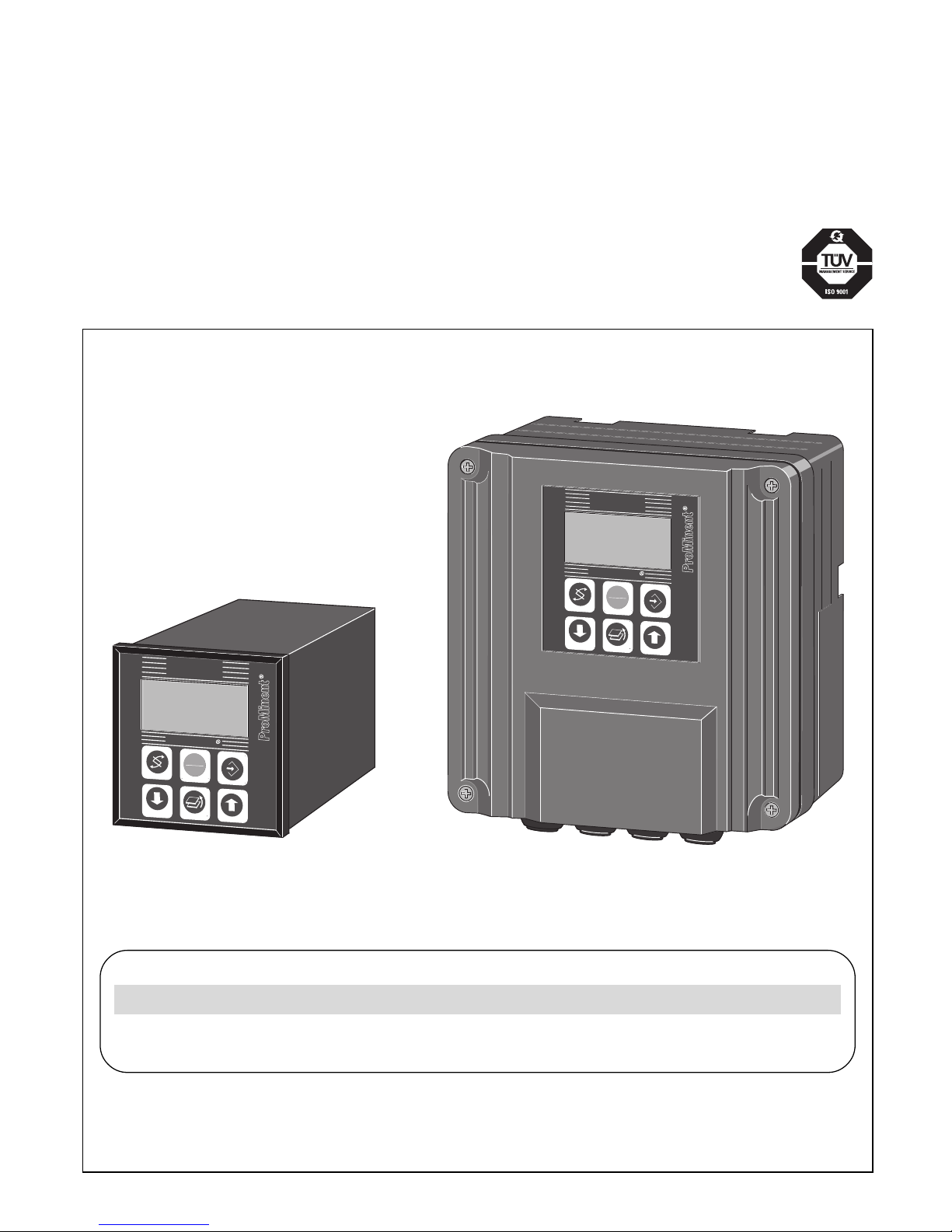
Typ/type W
Operating Instructions
DULCOMETER® D1C
Part 1: Mounting and installation instructions for wall-mounted and
control panel-mounted devices
ProMinent
®
T. Nr./P. No.: 987725 ProMinent Dosiertechnik GmbH · 69123 Heidelberg · Germany BA DM 123 04/03 G/GB/F/E
Identcode
D1C A
___ ___ ___ ___ ___ ___ ___ ___ ___ ___ ___ ___ ___
pH
7.43
pH
START
STOP
Temp.: 24.7
° C
DULCOMETER
pH
7.20
pH
START
STOP
DULCOMETER
DED1C1S001 DED1C1W001
G/GB/F/E
Typ/type D
Page 2

2
Betriebsanleitung in deutsch
von Seite 1 bis 21
Operating Instructions in English
from Page 23 to Page 41
GB
E
Page 3
23
1 Contents / General User Information
Please completely read through these operating instructions. Do not discard!
The warranty shall be invalidated by damage caused by operating errors!
Page
General User Information ............................................................................................................................ 23
Device Identification / Identity Code ........................................................................................................... 24
Device Overview / Controls ......................................................................................................................... 25
Functional Description ................................................................................................................................. 26
Mounting / Installation.................................................................................................................................. 27
Safety information ............................................................................................................................... 27
Technical Data .............................................................................................................................................. 33
Maintenance / Repair ................................................................................................................................... 37
Applicable Types of Enclosure / Standards ................................................................................................ 39
Spare Parts / Accessories............................................................................................................................ 40
Used Part Disposal....................................................................................................................................... 40
EC Declaration of Conformity ...................................................................................................................... 41
Overview of terminal arrangement ............................................................................................................... 42
Terminal diagrams ........................................................................................................................................ 44
General User Information
Please read the following information carefully and thoroughly. Knowledge of this information will greatly
increase the benefit you gain from the operating instructions.
Particular attention is drawn to:
• Lists
Instructions
Setting menus
NOTE
The information provided in a note is intended to make your work easier.
and safety information:
WARNING
This symbol draws attention to possible hazardous situations. Disregard of this information
may result in the direct threat to life and serious injuries.
CAUTION
This symbol draws attention to a possibly dangerous situation. Disregard of this
information may result in serious injuries or damage to property.
IMPORTANT
This symbol is used to draw attention to possible damaging situations. Disregard of this
information may result in damage to property.
SAFETY INFORMATION
CAUTION
• Please observe the parts of these operating instructions applicable to your specific type
of equipment! Applicable parts are listed in the device identification/ID code list!
• Correct measurement and metering is possible only with the probe in perfect working
order! The probe must be calibrated/checked at regular intervals!
Probe failure may cause the uncontrolled metering of chemicals.
Page 4
24
2 Device Identification / Identity Code
D1C A
Please enter the identity code of your device here.
D1C DULCOMETER® Controller Series D1C
W Wall mounting
D Control panel installation, 96 x 96 mm
Operating voltage
0 230 V 50/60 Hz
1 115 V 50/60 Hz
2 200 V 50/60 Hz (control panel installation only)
3 100 V 50/60 Hz (control panel installation only)
4 24 V AC/DC
Measured variable
B Bromine (0.1...13 mg/l) (3rd quarter 2001)
C Chlorine (0...0.5/2/10/20 mg/l)
L Conductivity (0…20/200/2000 µS/cm; 0…20/200 mS/cm)
P pH (0...14 pH)
R Redox (-1000...1000 mV)
H Hydrogen peroxide (1…20; 10…200; 100…2000 mg/l)
S Standard signal (0/4-20 mA)
A Peracetic acid (10…200; 100…2000 mg/l)
D Chlorine dioxide (0...0.5/2/10/20 mg/l)
Z Ozone (0...2 mg/l)
X Dissolved Oxygen (0.1...10/20 ppm)
T Temperature (0...100 °C)
Connection of measured variable
1 Terminal, standard signal 0/4-20 mA (signal converters necessary for controllers
with measured variable connection, standard signal 0/4-20 mA
2 SN6 connector for P or R
3 Terminal for L
4 Terminal PT 100 for T
5 Terminal mV for P or R
Correction variable
0 None
1 pH for chlorine
2 Temperature for P, D, H, A or L via terminal
3 Temperature for P, D, H, A or L via standard signal 0/4-20 mA
4 manual temperature entry for P, H, A or L
Feedforward control
0 None
1 Flow as standard signal 0/4-20 mA
2 Flow as frequency 0 - 500 Hz
3 Flow as frequency 0 - 10 Hz
Control input
0 None
1 Pause
Signal output
0 None
1 Standard signal 0/4-20 mA measured value
2 Standard signal 0/4-20 mA controlled variable
3 Standard signal 0/4-20 mA correction variable
42 standard signal outputs 0/4-20 mA, freely programmable (not for H, A)
Power control
G Alarm and 2 limit value relays
M Alarm and 2 solenoid valve relays (pulse length control)
R Alarm relay and actuator with feedback
Pump control
0 None
2 Two pumps
Control characteristic
0 None
1 Proportional control
2 PID control
Log output
0 None
Language
D German (E, F, N)
E English (D, F, N)
F French (D, E, N)
I Italian (D, F, S)
N Dutch (D, E, F)
S Spanish (D, I, F)
P Polish (D, E, A)
A Swedish (D, E, P)
B Portuguese (E, S, F)
U Hungarian (P, A, E)
G Czech
Page 5
25
®
DULCOMETER
®
STOP
START
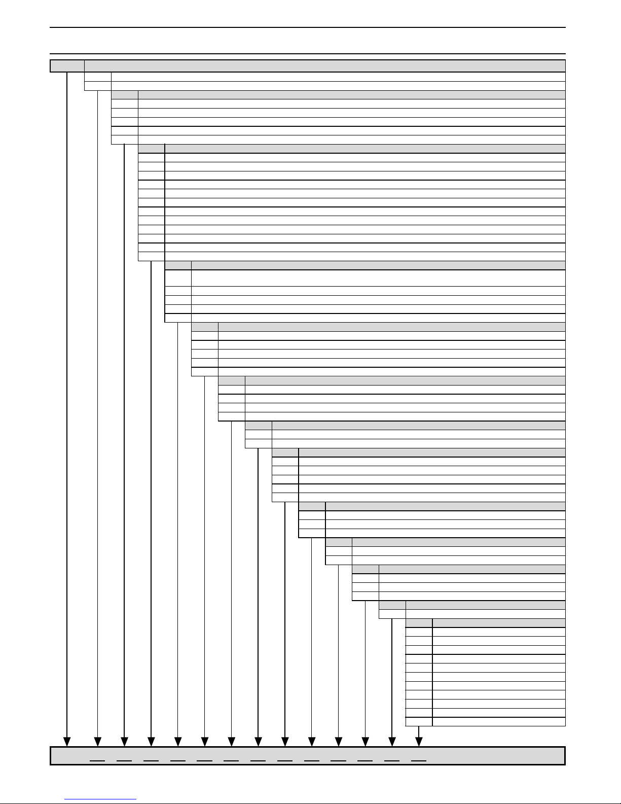
Display field
measured
variable
Graphic display
START/STOP
Button
ENTER
Button
UP
Button
CHANGE
Button
DOWN
Button
RETURN
Button
D1C
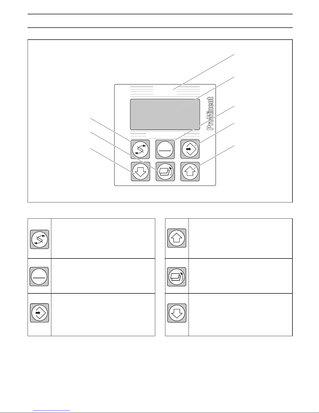
CHANGE button
To change over within a menu level
and to change from one variable to
another within a menu point.
START/STOP button
Start/stop of control and metering
function
ENTER button
To accept, confirm or save a displayed
value or status. For alarm acknowledgement.
3 Device Overview / Controls
D1C2-Cl-002-GB
STOP
START
UP button
To increase a displayed numerical
value and to change variables (flashing
display).
RETURN button
To exit operating menu (back to start
of relevant setting menu).
DOWN button
To decrease a displayed numerical
value and to change variables (flashing
display).
Page 6

26
4.1 Brief functional description
The DULCOMETER® D1C is a device designed for measuring, displaying and controlling measures
variables. With the corresponding expansion stage it can also process disturbance variables.
The measured variables to be processed are:
- pH, ORP
- Standard signal, Temperature
- Dissolved Oxygen
- Chlorine, ClO2, Br, O
3
- Conductivity
- H2O2 , peracetic acid
4.2 Mechanical design
The DULCOMETER® D1C is supplied in versions suitable for control panel installation and wall mounting.
4.2.1 Control panel installation in accordance with DIN 43700 (96 x 96 mm)
The DULCOMETER® D1C is a device suitable for control panel installation in accordance with DIN 43700
with the format 96 x 96 mm, depth 140 mm. In this installation arrangement, the device is completely
integrated in the control panel or installed in a housing. The device is electrically connected directly via
terminals at the rear.
The terminals as well as an SN6 socket for pH or redox input project beyond the rear panel.
Retaining brackets for mounting the device in the control panel are provided on the housing.
The display pc-board with the graphic display is located at the front. It features 6 operating buttons and a
transparent display window.
4.2.2 Wall mounting
The DULCOMETER® D1C W is suitable both for wall mounting as well as for installation in a control panel
(control panel installation kit, Part No. 792908). The durable plastic housing is made up of an upper section
and lower section. The graphic display and transparent display window are accommodated in the upper
section while the lower section houses the processor, power supply and options board. The connection to
the display is made by means of a ribbon cable. Electrical connection is made via the originally closed,
punch-out cable leadthroughs on the underside of the housing. On devices with an SN6 input (dependent
on identity code), the standard SN6 socket is located on the left-hand side. A wall mounting bracket is
provided at the rear of the device to facilitate simple wall mounting.
4.3 Electrical design
The device processes an input signal while taking into consideration disturbance variables and operator
inputs. The result is displayed and made available to other devices via a standard signal or a serial interface.
When equipped with corresponding actuators, the device can undertake control functions. It is designed to
activate metering pumps, solenoid valves, servo motors with feedback as well as mA standard signal. The
activation variable is recalculated every second.
The controller does not feature a separate power switch. It is therefore immediately ready for operation
after being connected to the power supply.
The devices correspond to relevant requirements concerning electrical operating equipment. For this
purpose, the following standards are complied with:
• Supply voltage in accordance with - DIN IEC 38
• Electrical safety in accordance with - EN 61010-1
• Emitted electromagnetic interference in accordance with - EN 55011 Gr. 1/Cl. A
4 Functional Description
Page 7

27
5.1 Safety information
WARNING
The device is suitable for installation in a control panel or in a corresponding housing (see
accessories). The device must not be placed into operation if not installed as intended!
CAUTION
• The generally applicable safety precautions must be observed for installation.
Corresponding national regulations must be complied with!
• The operating instructions must be read through carefully before starting any installation
and start-up procedures!
• Only specially trained and qualified personnel are permitted to carry out electrical
installation of the device!
• The power ratings specified on the device must agree with those of the supply voltage!
• The power connection line and the data lines must not be installed together with
interference-prone lines! If low electrical disturbance cannot be guaranteed in the
working environment, special interference suppression measures must be implemented!
Severe disturbances can cause malfunctions through to irreparable damage of the
device!
5.2 Mounting description, mechanical
Please remove the protective film from the display!
5.2.1 Mounting DULCOMETER® D1C D (control panel installation)
This device is designed specifically for installation in a control panel. The housing corresponds to DIN
43700.
The aperture in the control panel for installing the device is defined in DIN 43700.
We recommend a smaller aperture. In this way, the device is held more securely in place (reduced lateral
play) and the seal is pressed more evenly.
5 Mounting / Installation
92
+0,6
92
+0,6
90
+0,5
90
+0,5
DED1C1S003
Aperture to ProMinent
recommendation
Aperture to
DIN 43700
Page 8
28
To make aperture:
As an installation aid, a drill/punch template at a scale of 1:1 is provided with the device for the purpose of
optimally positioning the device on the control panel.
With the aid of a spirit level, align the template in the corresponding position on the control panel and
secure in this position. Mark the corner points with a centre punch and drill out with a 6 mm Ø twist drill.
Then saw out the intermediate web with a compass saw. Neatly rework the surfaces until the dimensions
are within the specified tolerances.
Cleanly deburr edges.
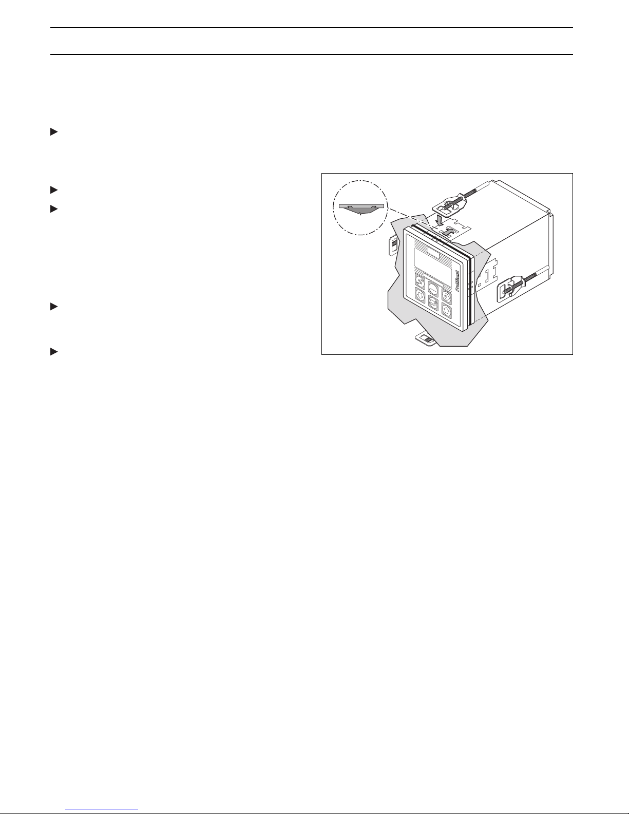
Before fitting the device into the control panel
aperture, check the position of the seal (must rest
on front shoulder). Working from the outside, fit the
device in the aperture, attach the retaining brackets
and slide back as far as it will go. All four retaining
brackets must be fitted otherwise the enclosure
class IP54 will not be complied with.
Using a suitable screwdriver, screw the threaded
pins forward until the seal is evenly pressed all
round.
Check once again that the seal is fitted correctly, if
necessary, release the threaded pins and correct
the position.
5.2.2 Mounting DULCOMETER® D1C W (wall mounting)
NOTE
The device should be mounted in such a position as to facilitate easy read-off and
operation (at eye-level where possible).
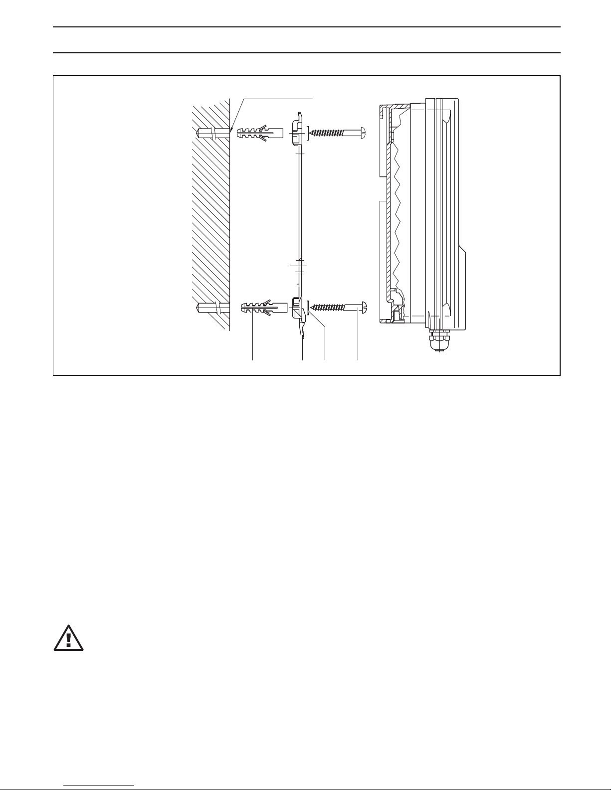
The device can be screwed directly onto the wall with the aid of the wall mounting bracket provided (drilling
template enclosed).
Securing material for wall mounting:
• Item (1) 3x button head screws 5x45
• Item (2) 3x U-washer 5.3
• Item (3) 3x plastic wall plug d8
The wall mounting bracket (4) can also be used as a drilling aid. For this purpose, set up the mounting
bracket in the corresponding position on the wall.
NOTE
Take particular care when setting up to ensure that sufficient space is available for the
purpose of installing the cables. A space of approx. 120 mm must be left at the top for the
“park position”.
Mark and drill the holes. Insert wall plugs (3) and secure mounting bracket with screws (1) and U-washers
(2). Mount device from above on mounting bracket, press slightly against the wall and slide upward by
approx. 4 mm until it is heard to engage in position.
DED1C1S004
®
S
TO
P
START
DULCOMETER
®
D1C
Mounting / Installation
Page 9
29
5.2.3 Control panel installation D1C W
A 4 mm wide flange acting as the stop for the control panel together with an all-round groove for a seal is
provided on the perimeter of the device. When mounted in a control panel, the entire front section
protrudes by approx. 35 mm from the control panel. The device is mounted from the outside in a prepared
aperture in the control panel. The device can be secured to the control panel from the inside with the
securing material provided.
Securing material for control panel installation:
• Item (1) 1x cellular rubber seal d3
• Item (2) 6x retaining bracket, galvanised steel
• Item (3) 6x PT self-tapping screw, galvanised
Procedure
Using the cut-out template provided, first mark the exact position of the device on the control panel. Where
possible, it should be positioned at eye-level. Ensure sufficient space is left at the top to allow for the “park
position”. Mark and drill the corners. Hole diameter 12 - 13 mm.
IMPORTANT
Dimensional deviations may occur as the result of photocopying the cut-out template.
Now make the aperture as specified in the drawing with the aid of a punch or compass saw. The control
panel should be 2 - 3 mm thick. Before fitting the device in the aperture, evenly press the seal into the
groove on the outside of the housing. With the aid of a second person if necessary, the controller can then
be firmly secured with the retaining brackets and screws to the control panel.
3421
D1C1(W) 003 D
Ø 8 x 50 deep drilled hole
Mounting / Installation
Page 10

30
Mounting with SN6 socket (depending on identity code)
Corresponding to the order, an SN6 input socket may be
preassembled on the device. This socket must first be removed
in order to facilitate installation in the control panel. For this
purpose, open device as described under Point 5.3.
By pressing the orange-coloured levers simultaneously,
disconnect connection cable from terminals No. 11 and 12.
Unscrew SN 6 socket (WAF 22) complete with O-ring.
After installing the controller in the control panel, the SN6
socket can be re-fitted together with the coaxial cable and
O-ring.
IMPORTANT
Ensure the O-ring is fitted correctly!
Reconnect cable to terminals 11 and 12.
5.3 Electrical installation
WARNING
• Electrical connection must not be carried out before the device has been installed in the
control panel!
• The supply voltage must be disconnected when removing the device together with the
connection lines!
• Generally, the device may only be opened by qualified personnel.
• Particular care must be taken before opening the device for the purpose of possible
service work to ensure that no voltage is applied to the device and the voltage supply
cannot be switched on while carrying out service work.
IMPORTANT
Tie together stranded wires with cable ties at a distance of 30 mm from the terminals! If
they work loose in the event of a defect, stranded wires carrying mains voltage must be
prevented from coming in contact with low voltage terminals!
5.3.1 Electrical installation D1C D (control panel installation)
Terminals are provided at the rear of the device to facilitate electrical connection. The number and type of
terminals depend on the type of device.
Not all devices are equipped with terminal row X1 (left).
Among other things, terminal row X2 (centre) serves the purpose of connecting the measured variable. The
measured variables pH and redox can be connected directly to the terminals with SN6 connectors or, as
other measured variables, via a mA signal. The jumper must be connected at terminals 9 and 10 of terminal
row X2 if pH or redox probes are connected to SN6 connectors or to the terminal without connection of
equipotential bonding!
Terminals rows XR1, XR2 and XR3 (right) serve the purpose of connecting power relays. The mains power
connection XP is located at the bottom right. An earthing cable is not necessary.
The connectors XHK are provided for service purposes.
Refer to the terminal connection diagrams for the connection terminals (see Page 42-53).
3 2 1
D1C1(W) 004 D
Control panel
Mounting / Installation
Page 11
31
a) b) c)
d)
e)
3
2
1
4
Cable ties
16 15 1413 12 11 10 9 8 7 6 5 4 3 2 1
123456789101112
21
2
1
N
21
321
L1
pH
®
pH
DULCOMETER
®
S
T
O
P
S
T
A
R
T
1) 2) 5)
3) 4)
D1C1(W) 005 D
a) b)
c) d)
6
5
DED1C1W 006 DED1C1W 007
Fig. 1: Rear row Fig. 2: Front row
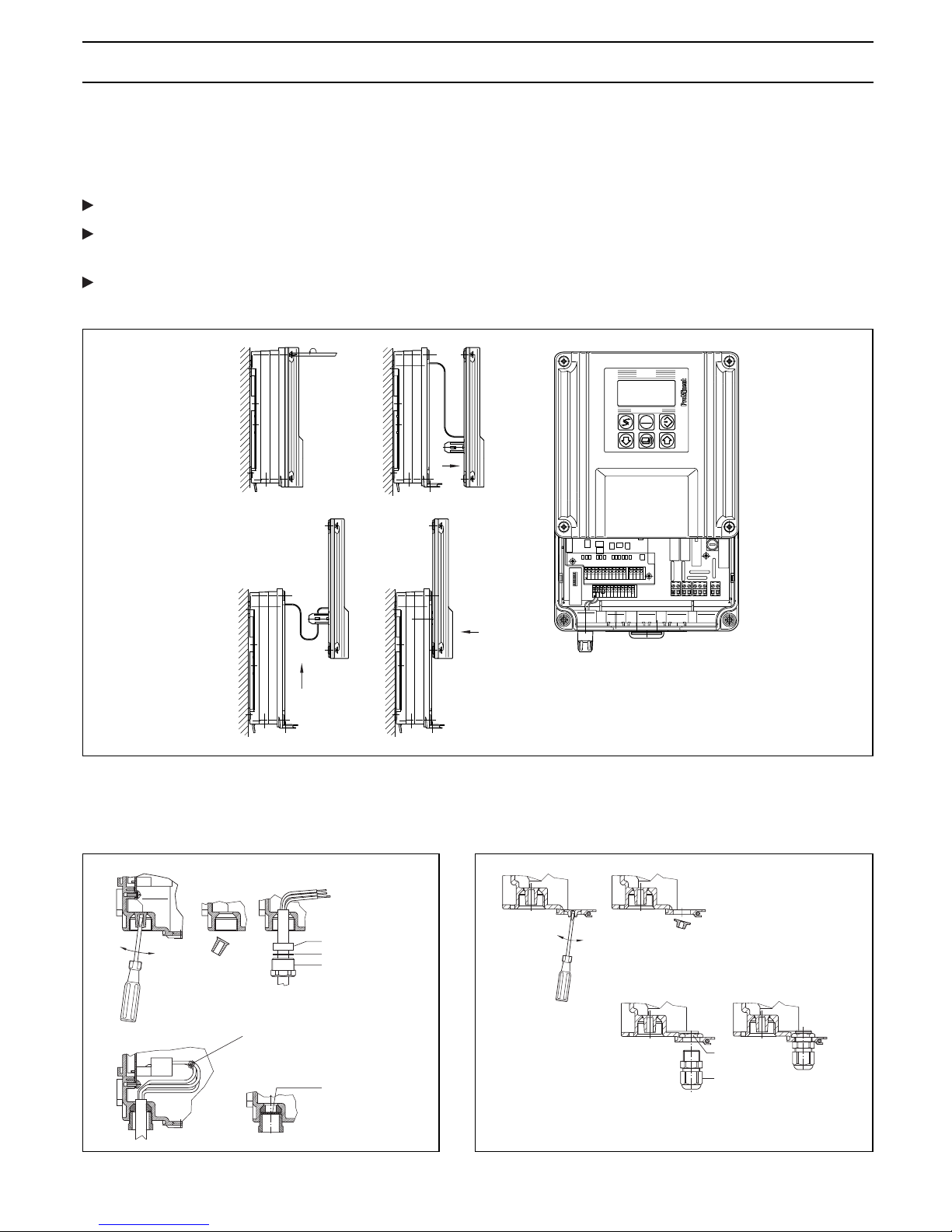
5.3.2 Electrical installation D1C W (wall mounting)
Opening the housing
The device should only be opened when it is mounted on a wall or installed in a control panel.
To open the housing, initially, the four captive countersunk screws must be released.
The upper section is additionally locked to the bottom section by means of snap hooks. The housing can
be opened by pulling the upper section forward thus releasing the snap hooks.
With the aid of the two guide rails, the upper section can be moved to the approx. 100 mm higher “park
position”. The fuse and all connection terminals are freely accessible in the park position.
Electrical installation for wall mounting
Initially, threaded holes must be broken out corresponding to the number of cables.
• Punch aids are provided to break out the individual threads.
Mounting / Installation
Page 12

32
• Use following tools to punch out holes:
Rear row (Fig. 1): Screwdriver DIN 5262-B, size 1 (Ø 4.5 mm)
Front row (Fig. 2): Screwdriver DIN 5262-B, size 0 (Ø 3.0 mm)
Remove cable sheathing over a sufficient length (corresponding to length of terminals). Fit screwed
gland (1), thrust ring (2) and seal (3) over cable and insert in threaded hole.
Screw in screwed gland and firmly tighten with WAF 19 spanner. Shorten stranded wires to the exact
overall length, then strip approx. 7 mm insulation and connect to terminals corresponding to the electrical
connection diagram.
Core sleeves may be used for the stranded wires. If too many threaded holes are punched out, they can
be closed off again with the dummy washers PG 11 (4) supplied with the device.
If the controller features an SN6 input (corresponding to identity code), the corresponding input socket is
located in the rear row on the left side in a PG 11 threaded hole. Any ProMinent cable combination coax
SN6 can be connected to this input.
Packing list, cable screwed glands
5x screwed gland PG 11 Item (1)
5x thrust ring PG 11 Item (2)
5x seal PG 11 inside Ø 9 mm Item (3)
3x seal PG 11 inside Ø 7 mm Item (3)
3x seal PG 11 inside Ø 5 mm Item (3)
2x seal PG 11 inside Ø 4 mm Item (3)
5x seal PG 11 2 x Ø 5 mm Item (3)
2x seal PG 11 2 x Ø 4 mm Item (3)
3x dummy washer PG 11 Item (4)
Additionally for expansion version
4 Stck. 4x screwed gland PG 7 Item (5)
4x lock nut PG 7 brass, nickel-plated Item (6)
The four additional cut-outs in the front row can be used for PG 7 screwed glands. All commercially
available PG 7 screwed glands (suitable for type of enclosure IP65) with lock nut (brass, galvanised, nickelplated) can be used as cable screw fittings.
Available from ProMinent under:
1x cable screwed gland PG 7, black Part No. 703896
1x lock nut PG 7 brass, nickel-plated Part No. 703819
Fit lock nut PG 7 (6) on the inside and mount PG 7 screwed gland (5) from outside and firmly tighten
(WAF 15).
Electrical connection for control panel installation
Normally, only the rear row of threaded holes should be used on devices mounted in a control panel. The
front row (PG 7 cut-outs) are located outside the control panel. The cable screw fittings supplied with the
device are not required for control panel installation. In this case, the individual stranded wires (without pullrelief and seal) are routed directly through the holes and connected to terminals corresponding to the
electrical connection diagram. The holes are broken out as described above.
Mounting / Installation
Page 13

33
Temperature specifications D1C D Control panel Wall mounting
Permissible ambient temperature installation
Basic version: 0 °C...50 °C -5 °C...45 °C
Expansion version: with position feedback
or with correction value via mA
or with disturbance variable via mA 0 °C...45 °C -5 °C...40 °C
D1C W
Permissible ambient temperature
Basic version: -5 °C...50 °C
Expansion version: with position feedback
or with correction value via mA
or with d isturbance variable via mA -5 °C...40 °C
Permissible storage temperature: -10 °C...70 °C
Material specifications / chemical resistance
Part Material
Housing and frame D1C D PPO GF 10
Housing D1C W PPE GF 10
Rear panel D1C D PPE GF 20
Membrane keypad Polyester film PET
Seal Cellular rubber CR
Inner seal, D1C D Silicon-based sealing compound
Retaining bracket and screws Galvanised, zinc-plated steel
M5 screws A2
Chemical resistance:
The device is resistant to normal atmospheres in installation rooms.
Dimensions and weights
D1C D
96 x 96 mm in accordance with DIN 43700, depth 140 mm
Device weight without packing: approx. 850 g
Gross weight of device with packing: approx. 1200 g
D1C W
198 x 200 x 76 mm (W x H x D) Wall mounting
198 x 200 x 35 mm (W x H x D) Control panel installation, external
198 x 200 x 38 mm (W x H x D) Control panel installation, internal
Device weight without packing: approx. 1.2 kg
Net weight of device with packing: approx. 2.0 kg
Electrical data
Probe input via terminals
(X2.12 ... X2.9): Input resistance: > 5 x 10¹¹ Ω
Input resistance of reference electrode with respect to
chassis ground: <1 kΩ
Input range: ±1 V
Accuracy: ±0.5 % of input range
Resolution: 0.0625 % of input range
Connection option for one equipotential bonding electrode
(alternatively, two connection terminals are to be connected
by a wire jumper).
6 Technical Data
Page 14

34
Probe input via
SN6 socket (X2.12 ... X2.9): Input resistance: 1012 Ω
Other data same as for “Probe input via terminals”
Standard signal input
(all measured variables)
(X2.12 ... X2.9): Input range: 0/4…20 mA (programmable)
Input resistance: 50 Ω
Accuracy: 0.5 % of input range
Resolution: 0.014/0.012 mA
Supply voltage and current for external electronics:
19 V ±1.5 V, 20 mA
Conductivity input via
terminals (X2.12 ... X2.9): 2 electrode measuring cells via 2-conductors
2 electrode measuring cells via 4-conductors
4 electrode measuring cells via 4-conductors
Measuring range: 20, 200, 2000 µS/cm
20, 200 µS/cm
Measuring span: 1 : 100
Cell constant: 0.006…12.0 cm-1 depending on measuring range
Probe activation: Sinusoidal 56 Hz or 2.7 kHz
depending on measuring range
Pt 100 input (X2.8, X2.7): Input range: 0 °C…100 °C
Accuracy: ±0.5 °C
Resolution: 0.1 °C
Frequency outputs
(2 reed relays)
for pump activation
(X2.6, X2.5 and X2.4, X2.3): Type of contact: n/o contact noise-suppressed with Varistors
Load capacity: 25 V peak, 0.100 A switching current
Contact lifespan: >50 x 106 switching operations at
contact load 10 V, 10 mA
Max. frequency: 8.33 Hz (500 strokes/min)
Closing time: 100 ms
Standard signal output mA
(X2.2, X2.1): Galvanically isolated from remaining inputs and outputs
Insulation voltage: 500 V
Output range: 0/4...20 mA (programmable)
Max. load: 600 Ω current output 1
400 Ω current output 2
Accuracy: 0.5 % of output range referred to
displayed value
Technical Data
Page 15

35
Standard signal input
for correction variable or
disturbance variable mA
(X1.16 ... X1.14): Galvanically isolated from other inputs and outputs
Insulation voltage: 500 V
Input range: 0/4…20 mA (programmable)
Input resistance: 50 Ω
Accuracy: 0.5 % of input range
Resolution: 0.014/0.012 mA
Supply voltage and current for external electronics:
22 V ±1.5 V, 20 mA
Standard signal output mA
(X1.13, X1.12): Galvanically isolated from other inputs and outputs
Insulation voltage: 500 V
Output range: 0/4…20 mA (programmable)
Max. load: 600 Ω current output 1
400 Ω current output 2
Accuracy: 0.5 % of output range referred to displayed value
Digital input (X1.10, X1.9 Common reference potential and with RS interface but galvanically
and X1.7, X1.6): isolated from remaining inputs and outputs
Insulation voltage: 500 V
- Pause
- Disturbance variable up to 10 Hz or up to 500 Hz
(according to identity code/programmable)
Position feedback input
(X1.3 ... X1.1): Galvanically isolated from other inputs and outputs
Insulation voltage: 500 V
Potentiometer to be connected: 900 Ω...10 kΩ
Accuracy (not including potentiometer error):
1 % of input range
Resolution: 0.5 % of input range
Actuating time: min.: 25 s
max.: 180 s
Power relay output for
controlled variable output (M, R)
or limit value signalling (G)
(XR1 and XR2): Type of contact: Changeover contact, noise-suppressed
with varistors
Load capacity: 250 V AC, 3 A, 700 VA
Contact lifespan: >20 x 106 switching operations
IMPORTANT
The supply voltage applied at relays XR1-XR3 must be identical to the supply voltage
of XP.
Technical Data
Page 16

36
Power relay output
for alarm triggering (XR3): Type of contact: Changeover contact, noise-suppressed
with varistors
Load capacity: 250 V AC, 3 A, 700 VA
Contact lifespan: >20 x 106 switching operations
IMPORTANT
The supply voltage applied at relays XR1-XR3 must be identical to the supply voltage
of XP.
Rated voltage (XP): 100/200 V AC, 50/60 Hz (D1C D only)
Maximum current intake: 150 mA at 100 V AC
75 mA at 200 V AC
Internal fuse protection with: 5 x 20 mm miniature fuse
160 mA, 250 V slow-blow
Rated voltage (XP): 115/230 V AC, 50/60 Hz
Maximum current intake: 140 mA at 115 V AC
70 mA at 230 V AC
Internal fuse protection with: 5 x 20 mm miniature fuse
160 mA, 250 V slow-blow
Rated voltage (XP): 24 V DC or 24 V AC, 50/60 Hz
(operation with safety extra-low voltage only!)
Internal fuse protection with: 5 x 20 mm miniature fuse
315 mA, 250 V slow-blow
Technical Data
Page 17

37
Input /
Output
terminals
Power supply
pc-board on rail 1
Fuse
Rear cover
Terminal block with
flange screw fitting
Pin strip
SN6-connector
Safety information
WARNING
• The device or system must be disconnected from the power supply before starting any
maintenance work. The DULCOMETER® D1C does not feature a separate power switch!
The power supply must therefore be interrupted by means of an external master switch
or by a main fuse. General safety regulations are applicable at all times!
Even when the voltage supply is switched off, mains power may still be applied at
terminals XR 1-3!
• Only use fuses of the specified manufacturer!
Only use 5 x 20 mm miniature fuses!
Fuse rating at mains voltage 100…240 V: 0.160 A slow-blow, Part No. 712048
24 V: 0.315 A slow-blow, Part No. 712026
Fuse change D1C D:
The device can be opened from the rear. For this purpose:
Release flange screw connections of plug-in terminal strips
Unplug terminal strips together with electrical connections
Release SN6 connector (if fitted) and unplug from socket
Unscrew rear panel and remove; the captive screws are located on the rear cover
The power board is located on the right-hand side (viewed from rear); pull out towards rear
If necessary, remove fuse and replace by new fuse
Take particular care when re-inserting the card to ensure that it is fitted in the same rail otherwise
electrical connection to the display board will not be established
Press card fully forward onto plug contacts
Reinstall rear housing cover and firmly tighten
Reconnect terminal strips with electrical lines to corresponding pin strips and firmly tighten.
Maintenance / Repair
DED1C1S005
Page 18

38
Fuse change D1C W:
• The above-specified safety measures must be implemented (disconnection from mains!) before replacing
the device fuse:
The mains power fuse is located in a closed fuse holder (6) in the terminal box.
Open device and set in “park position”
Release bayonet catches of fuse holder
Remove fuse and replace by new fuse
Lock bayonet catch and close housing
Maintenance / Repair
6534
2
1
......
D1C-..
FW-_._
DED1C1W010
Upper section of housing
inside
Lower section of housing
inside
Sectional
side view
Item (1) Electrical assembly, display Item (4) Ribbon cable
Item (2) Ribbon cable Item (5) Electrical assembly, processor
Item (3) Electrical assembly I/O/S Item (6) Fuse holder
Page 19

39
8.1 Electric shock and moisture protection (IP)
D1C D: Device in installed condition: Type of enclosure DIN 40050 - IP 54
D1C W: Device in sealed housing type of enclosure IP 65 in accordance with DIN VDE 0470 corresponding
to EN 60529 and IEC 529
outer seal (control panel installation): type of enclosure IP 54 in accordance with DIN VDE 0470
corresponding to EN 60529 and IEC 529.
8.2 Electrical safety/interference suppression
EC low voltage guideline (73/23/EEC) consequently 93/44/EEC
EC EMC guideline (89/336/EEC) consequently 92/31/EEC being prepared
Supply voltage in accordance with DIN IEC 38
Electrical safety in accordance with EN 61010-1
Electromagnetic emitted interference in accordance with EN 55011 Gr. 1/Cl. B
Interference immunity in accordance with IEC 801-2, -3, -4 or DIN VDE 0843, Part 2, Part 3, Part 4 or EN
50082-2
EN 60335-1 Safety of electrical devices for household use
EN 50081-1 EMC, emitted interference, residential areas
EN 50082-2 EMC, emitted interference, industrial areas
EN 60555-2 EMC, reactions in power supply networks, harmonics
EN 60555-3 EMC, reactions in power supply networks, voltage fluctuations
8.3 Test in moist changeable climate
D1C D: Permissible relative humidity: max. 80 % (condensation not permitted)
WARNING
The device is not suitable for use in a moist changeable climate as there is no sealed
housing and constant exchange of air!
D1C W: Moist changeable climate in accordance with FW DIN 50016.
8 Applicable Types of Enclosure / Standards
Page 20

40
9 Spare Parts / Accessories
- Housing for wall mounting, including securing material, Order No. 790235
- Mounting kit for control unit installation, Order No. 792908
- Sensors, instrument leads, see product catalogue, chap. 6
- Measuring transducers, see product catalogue, chap. 5
10 Used Part Disposal
NOTE
Plastics and scrapped electronic components are special waste and must be recycled!
Used electronic components are accepted by municipal collection points set up by towns
and municipal districts or ProMinent branches!
With the exception of the electrical assemblies, the design of the device comprised few
mechanical parts. They are relatively easy to separate into specific materials; e.g. no
metallic thread inserts were used in the housing. With the exception of the membrane
keypad, these parts can be re-introduced to the material recycling system (see under
Chap. 6 “Material Specifications”)!
The membrane keypad is to be classified and disposed of in compliance with applicable
municipal guidelines!
9 Spare Parts / Accessories
10 Used Part Disposal
Page 21

41
EC Declaration of Conformity
Page 22

42
Übersicht Klemmenanordnung / Overview of terminal arrangement
Klemmenanordnung
Schalttafelgerät
Terminal order
switchboard mounting
X1
X2
XR1
XP
XR2
XR3
X2
Page 23

43
Klemmenanordnung
Wandgerät
Terminal order
wall mounting
X1
X2
XR1 XR3XR2 XP
ACHTUNG
Nicht die Klemmenbezeichnungen von X2 und X1
verwechseln!
IMPORTANT
Do not confuse the terminal designations X2 and X1!
Page 24

44
pH/Redox über Klemme / pH/ORP via terminals
Pt 100 (temperature)***
Mains power Mains power
Netz
Extern Pumpe 2 senken
Extern Pumpe 1 heben
Normsignal-Ausgang 1
0/4-20mA
Standard signal output 1
0/4-20mA
Netz
external
Extern
(potentialfrei)
(potentialfrei)
with
without
Liquid reference potential
mV-input terminal
Terminal connection for pH / ORP via terminals
mV
Ref.
Pt 100 (Temperatur)***
87
65 43
21
Ref.
mV
Potentialausgleich
pH/Redox (ORP)
pH/Redox (ORP)
mV-Eingang-Klemme
ohne/
mit/
Potentialausgleich
Liquid reference potential
Klemmenanschluss für pH / Redox über Klemme
X2
1211109
1211109
+
-
pH/Redox (ORP)
**
Te mperature
input (Pt 100)
Temperatur-
Eingang (Pt 100)
Frequency outputs
(pumps)
Frequenz-Ausgänge
(Pumpen)
i. e. recorder
z. B. Schreiber
internal
Intern
External pump 2 decrease (potencial free)
External pump 1 increase (potencial free)
*** Correction variable for pH (see also p. 53)
*** Korrekturgröße für pH (vgl. auch S. 53)
** IMPORTANT: When connecting the electrode without liquid reference potential
clamp terminal X2.9 and X2.10 have to be closed.
** ACHTUNG: Bei Anschluss der Sonde ohne Potenzialausgleich
die Klemmen X2.9 u. X2.10 brücken.
Page 25

45
pH/Redox über SN6-Eingang / pH/ORP via SN6 socket
Pt 100 (temperature)***
Mains power Mains power
Netz
Extern Pumpe 2 senken
Extern Pumpe 1 heben
Normsignal-Ausgang 1
0/4-20mA
Standard signal output 1
0/4-20mA
Netz
external
Extern
(potentialfrei)
(potentialfrei)
with
without
SN6-input
Pt 100 (Temperatur)***
87
65 43
21
pH/Redox (ORP)
SN6-Eingang
ohne/
mit/
Potentialausgleich
Liquid reference potential
Klemmenanschluss für pH / Redox über SN6-Eingang
Terminal connection for pH / ORP via SN6 socket
X2
1211109
1211109
+
-
pH/Redox (ORP)
**
Te mperature
input (Pt 100)
Temperatur-
Eingang (Pt 100)
Frequency outputs
(pumps)
Frequenz-Ausgänge
(Pumpen)
i. e. recorder
z. B. Schreiber
internal
Intern
Liquid reference potential
SN6
Potentialausgleich
SN6
pH/Redox (ORP)
*
*
clamp terminals X2.12 and X2.11 are connected internaly.
* Bei Version D (Schalttafeleinbau) sind
die Klemmen X2.12 und X2.11 intern verdrahtet.
* Version D (Control panel installation) only:
External pump 2 decrease (potencial free)
External pump 1 increase (potencial free)
*** Correction variable for pH (see also p. 53)
*** Korrekturgröße für pH (vgl. auch S. 53)
** ACHTUNG: Bei Anschluss der Sonde ohne Potenzialausgleich
die Klemmen X2.9 und X2.10 brücken.
** IMPORTANT: When connecting the electrode without liquid reference potential
clamp terminal X2.9 and X2.10 have to be closed.
Page 26

46
F, Br2, Cl2, ClO2, O2, O3, mA, mS/cm, pH*, Redox / ORP*, ºC*
Pt 100 (temperature)***
Mains power Mains power
** See also D1C, part 2 "Measured value setting"-
"range adjustment" and operating instructions DMT!
Netz
Extern Pumpe 2 senken
Extern Pumpe 1 heben
Normsignal-Ausgang 1
0/4-20 mA
Standard signal output 1
0/4-20 mA
Netz
external
** Siehe auch D1C, Teil 2 "Messbereich einstellen"
"Bereichzuordnung" und Betriebsanleitung DMT!
Extern
(potentialfrei)
(potentialfrei)
Assignment variants
Measured variable
Standard signal input (mA)
Pt 100 (Temperatur)***
87
65 43
21
Normsignal-Eingang (mA)
Belegungsvarianten
Klemmenanschluss für
Terminal connection for
F, Br2, Cl2, ClO2, O2, O3, mA, mS/cm, pH*, Redox*, ˚C*
X2
1211109
1211109
+
-
Messgröße
Temperature
input (Pt 100)
Temperatur-
Eingang (Pt 100)
Frequency outputs
(pumps)
Frequenz-Ausgänge
(Pumpen)
***Correction variable for pH, ClO2, mS/cm (see also p. 53)
*** Korrekturgröße für pH, ClO2, mS/cm (vgl. auch S. 53)
i. e. recorder
z. B. Schreiber
internal
Intern
External current source
1211109
ProMinent transducer
2
1
ProMinent Umformer
+
-
+
-
+
-
+
-
+
-
+
-
ProMinent DMT
8
7
**
passives Normsignal 4 - 20 mA
aktives Normsignal 0/4 - 20 mA
Externe Stromquelle
active standard signal 0/4 - 20 mA
passive standard signal 4 - 20 mA
External pump 2 decrease (potencial free)
External pump 1 increase (potencial free)
X1
* Nur mit Umformer
* Only with transducer
Page 27

47
Leitfähigkeit / conductivity
Normsignal-Ausgang 1
0/4-20mA
Standard signal output 1
0/4-20mA
External pump 2 decrease (potencial free)
External pump 1 increase (potencial free)
Pt 100 (temperature)***
Mains power Mains power
Netz
Extern Pumpe 2 senken
Extern Pumpe 1 heben
Netz
external
Extern
(potentialfrei)
(potentialfrei)
Conductivity input
Terminal connection for conductivity
Pt 100 (Temperatur)***
87
65 43
21
Leitfähigkeits-
Eingang
Klemmenanschluss für Leitfähigkeit
X2
1211109
+
-
Temperature
input
Temperatur-
Eingang
Frequency outputs
(pumps)
Frequenzausgänge
(Pumpen)
***Correction variable for mS/cm (see also p. 53)
*** Korrekturgröße für mS/cm (vgl. auch S. 53)
i. e. recorder
z. B. Schreiber
internal
Intern
2-Elektroden-
Messzelle
2-Elektroden-
Messzelle,
4-Leiter-Anschluss
4-Elektroden-
Messzelle
current b
current a
voltage b
voltage a
Strom b /
Strom a /
Spannung b /
Spannung a /
four wire connection
two electrodes
measuring cell,
measuring cell
two electrodes
measuring cell
four electrodes
Page 28

48
mit Grenzwertrelais / with limit value relays
Klemmenanschluss mit Grenzwertrelais
Leistungsrelais-
Ausgänge
Power relay output
for alarm triggering
Leistungsrelais-
Ausgang zur
Alarmgabe
Internal
power supply
Interne Spannungs-
versorgung
XR2
XR1
XP
XR3
Terminal connection with limit value relay
Power relay
output
1
2
12
L1
N
1
23
external
Extern
internal
Intern
Horn
Hupe
limit relay 1
limit relay 2
Grenzwertrelais 1
Grenzwertrelais 2
Speise-
spannung*
Speise-
spannung**
Speise-
spannung**
Speise-
spannung**
HINWEIS: zu Relais XR3: Das Gerät ist in betriebs-
bereitem Zustand und es steht kein Alarm an.
NOTE: to relay XR3: The device is shown ready and no
alarm is present.
feed
voltage**
feed
voltage**
feed
voltage*
feed
voltage**
is not relevant !
* With 24V DC polarity on feed voltage
Speisespannung ohne Bedeutung !
Bei 24 V DC ist die Polarität der
*
ACHTUNG: Die Speisespannung, die an
die Relais XR1 - XR3 gelegt wird, muss
identisch mit der Speisespannung von XP sein!
** IMPORTANT: The feed voltage to be connected to
the relays XR1 - XR3, has to be identically
with the feed voltage of XP.
**
Page 29

49
mit Magnetventilen / with solenoid valves
Klemmenanschluss mit Magnetventilen
Interne Spannungs-
versorgung
Terminal connection with solenoid valves
Leistungsrelais-
Ausgänge
Leistungsrelais-
Ausgang zur
Alarmgabe
Power relay
output
Power relay output
for alarm triggering
Internal
power supply
XR2
XR1
XP
XR3
1
2
12
L1
N
1
23
external
Extern
internal
Intern
Horn
Hupe
solenoid valve 1
solenoid valve 2
Magnetventil 1
Magnetventil 2
Speise-
spannung*
Speise-
spannung**
Speise-
spannung**
feed
voltage**
feed
voltage**
feed
voltage*
Speise-
spannung**
feed
voltage**
ACHTUNG: Die Speisespannung, die an die Relais
XR1 - XR3 gelegt wird, muss identisch
mit der Speisespannung von XP sein!
is not relevant !
* With 24V DC polarity on feed voltage
Speisespannung ohne Bedeutung !
Bei 24 V DC ist die Polarität der
*
**
NOTE: to relay XR3: The device is shown ready and no
alarm is present.
HINWEIS: zu Relais XR3: Das Gerät ist in betriebs-
bereitem Zustand und es steht kein Alarm an.
** IMPORTANT: The feed voltage to be connected to
the relays XR1 - XR3, has to be identically
with the feed voltage of XP.
Page 30

50
mit Stellmotor / with servomotor
Klemmenanschluss mit Stellmotor
Leistungsrelais-
Ausgänge
Power relay
output
Leistungsrelais-
Ausgang zur
Alarmgabe
Power relay output
for alarm triggering
Interne Spannungs-
versorgung
Internal
power supply
Terminal connection with servomotor
Stellungsrückmelde-
Eingang
Position feedback
input
XR2
XR1
XP
XR3
X1
1
2
12
L1
N
1
23
321
-
+
S
external
Extern
internal
Intern
S...Schleifer / S...slider
geschlossen / closed
offen / open
Öffner / to open
Schließer / to close
S
Actuator motor
Stellmotor
Horn
Hupe
Speise-
spannung*
Speise-
spannung**
feed
voltage**
feed
voltage*
Speise-
spannung**
feed
voltage**
M
is not relevant !
* With 24V DC polarity on feed voltage
Speisespannung ohne Bedeutung !
Bei 24 V DC ist die Polarität der
*
NOTE: to relay XR3: The device is shown ready and no
alarm is present.
HINWEIS: zu Relais XR3: Das Gerät ist in betriebs-
bereitem Zustand und es steht kein Alarm an.
ACHTUNG: Die Speisespannung, die an die Relais
XR1 - XR3 gelegt wird, muss identisch
mit der Speisespannung von XP sein!
**
** IMPORTANT: The feed voltage to be connected to
the relays XR1 - XR3, has to be identically
with the feed voltage of XP.
Page 31
51
mit Normsignal-Ausgang 2, mit Pause / with standard signal
output 2, with pause
Standard signal
output 2
0/4-20mA
Digital-
Eingang
Anschlussdetails Normsignalausgang 2 / Digitaleingang Pause
Connection details Standard signal output 2 / Digital input pause
X1
Intern
Normsignal-
Ausgang 2
Digital input
-
13+12
10 9 8
external
Extern
internal
-
+
Potenzialfreier
Kontakt nötig!
potential free connection
necessary.
i. e. recorder
z. B. Schreiber
Pause
-
+
Page 32

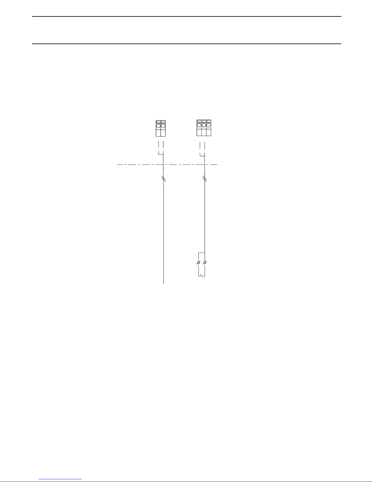
52
mit Störgröße / with disturbance variable
Anschlussdetails Störgröße
Digital-
Eingang
Digital input
Normsignal-Eingang
für Korrekturgröße oder Störgröße (mA)
Connection details disturbance variable
X1
external
Extern
internal
Intern
Standard signal input
correction variable or disturbance variable (mA)
Assignment variants
Belegungsvarianten
Disturbance variable (mA) i. e. flow signal from:
765
-
+
16 15 14
16 15 14
External current source
Measuring transducer
2
1
Messumformer
+
-
+
-
+
-
+
-
passives Normsignal 4 - 20 mA
aktives Normsignal 0/4 - 20 mA
Externe Stromquelle
active standard signal 0/4 - 20 mA
passive standard signal 4 - 20 mA
-
+
disturbance variable frequency
Störgröße Frequenz
X1
Störgröße (mA) z.B. Durchfluss-Signal von:
potential free connection
necessary.
Potenzialfreier
Kontakt nötig!
Electromagnetic
flow meters
Magnetisch-induktivem
Wassermesser
Contact water meter*
Kontaktwassermesser *
* IMPORTANT: Note maximum frequency.
* ACHTUNG: Maximalfrequenz beachten!
Page 33

53
mit Korrekturgröße / with correction variable
Anschlussdetails Korrekturgröße
Connection details correction variable
Normsignal-Eingang
für Korrekturgröße oder Störgröße (mA)
Temperature
input (Pt 100)
Temperatur-
Eingang (Pt 100)
X1
external
Extern
internal
Intern
Standard signal input
correction variable or disturbance variable (mA)
Assignment variants
Belegungsvarianten
87
X2
1615 14
1615 14
1615 14
+
-
+
-
+
-
ProMinent transducer
2
1
+
-
+
-
+
-
ProMinent DMT
aktives Normsignal 0/4 - 20 mA
active standard signal 0/4 - 20 mA
passive standard signal 4 - 20 mA
X1
ProMinent Umformer
8
7
**
passives Normsignal 4 - 20 mA
Externe Stromquelle
External current source
Pt 100 (temperature)
Pt 100 (Temperatur)
** Siehe auch D1C, Teil 2 "Messbereich einstellen"
"Bereichzuordnung" und Betriebsanleitung DULCOMETER
®
DMT!
** See also D1C, part 2 "Measured value setting"-
"range adjustment" and operating instructions DULCOMETER
®
DMT!
Page 34

54
Page 35

108
©1999 ProMinent Dosiertechnik GmbH · 69123 Heidelberg · Germany
Operating Instructions DULCOMETER® D1C, Part 1, issue 04/03
Subject to technical modifications · Printed in Germany
ProMinent Dosiertechnik GmbH
Im Schuhmachergewann 5-11 · 69123 Heidelberg · Germany
Postfach 101760 · 69007 Heidelberg · Germany
Tel.: +49 6221 842-0 · Fax: +49 6221 842-419
info@prominent.de · www.prominent.de
 Loading...