

Page 1

C
o
n
d
u
c
t
iv
it
y
100
µs/cm
S
T
A
R
T
S
T
O
P
D
U
L
C
O
M
E
T
E
R
Part No. 987926 ProMinent Dosiertechnik GmbH · D-69123 Heidelberg · Germany BA DM 085 08/01 GB
Operating Instructions
DULCOMETER® D1C
Part 2: Adjustment and Operation,
Measured Variable Conductivity
ProMinent
®
D1C2-Leit.-001-GB
Please completely read through operating instructions! · Do not discard!
The warranty shall be invalidated by damage caused by operating errors!
Page 2
2
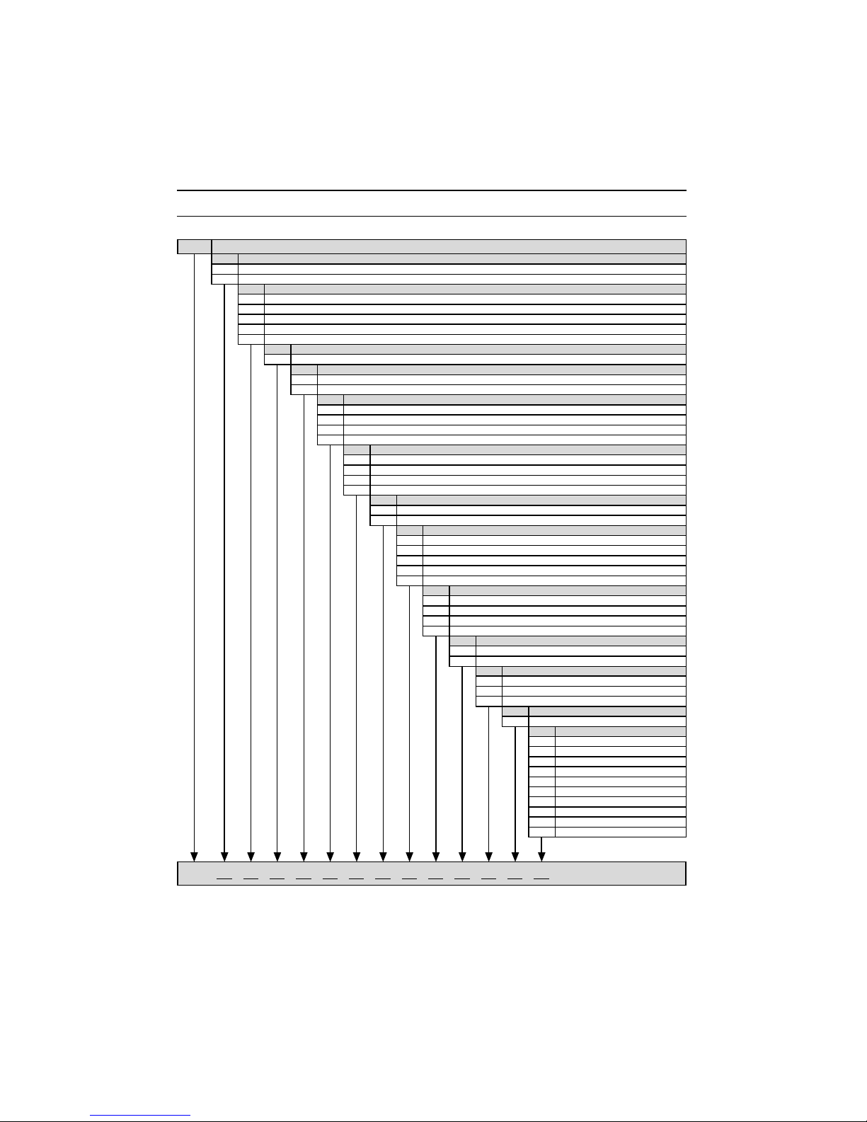
Please enter the identity code of your device here!
1 Device Identification / Identy Code
D1C A L 0 E
D1C A DULCOMETER® Controller Series D1C / Version A
Type of mounting
D Control panel installation 96 x 96 mm
W Wall mounting
Operating voltage
0 230 V 50/60 Hz
1 115 V 50/60 Hz
2 200 V 50/60 Hz (only with control panel installation)
3 100 V 50/60 Hz (only with control panel installation)
4 24 V AC/DC
Measured variable
L Conductivity
Connection of measured variable
1 Terminal, standard signal 0/4-20 mA
3 Terminal, conductive conductivity
Correction variable
0 None
2 Temperature via terminal (PT 100)
3 Temperature via standard signal 0/4-20 mA
4 Manual temperature entry
Feed forward control
0 None
1 As standard signal 0/4-20 mA
2 As frequency 0-500 Hz
3 As frequency 0-10 Hz
Control input
0 None
1 Pause
Signal output
0 None
1 Standard signal 0/4-20 mA measured value
2 Standard signal 0/4-20 mA control variable
3 Standard signal 0/4-20 mA correction variable
4 2 standard signal 0/4-20 mA output, free programmable
Power control
A Alarm relay
G Alarm and 2 limit value relays
M Alarm and 2 solenoid value relays
R Alarm relay and servomotor with feedback
Pump control
0 None
2 Two pumps
Control characteristic
0 None
1 Proportional control
2 PID control
Log output
0 None
Language
DGerman
E English
F French
I Italien
N Dutch
S Spanish
P Polish
ASwedish
B Portuguese
U Hungarian
Page 3
3
2 Contents / General User Information
Page
Device Identification / Identity Code ............................................................................................................. 2
General User Information ............................................................................................................................... 3
Device Overview / Controls ........................................................................................................................... 4
Functional Description ................................................................................................................................... 5
Display Symbols ............................................................................................................................................. 6
Operation ........................................................................................................................................................ 7
Restricted Operating Menu ............................................................................................................................ 8
Overview ................................................................................................................................................ 8
Layout .................................................................................................................................................... 9
Description .......................................................................................................................................... 10
Complete Operating Menu ........................................................................................................................... 14
Overview .............................................................................................................................................. 14
Description .......................................................................................................................................... 15
EC Declaration of Conformity ...................................................................................................................... 27
Troubleshooting ........................................................................................................................................... 28
General User Information
These operating instructions describe the technical data and function of the series DULCOMETER® D1C
controller, provide detailed safety information and are divided into clear steps. The activities to be carried
out are identified by bold bullets (•).
IMPORTANT:
Please observe the parts of these operating instructions applicable to your particular
version! This is indicated in the Section “Device Identification / Identity Code”!
IMPORTANT:
Correct measuring and dosing is only possible in the case of impeccable operation of the
probe. The probe has to be calibrated / checked regularly!
Page 4

4
®
DULCOMETER
®
S
T
O
P
S
T
A
R
T
Graphic display
Push-button
"Start/stop"
Push-button
"Enter"
Push-button
"Up"
Push-button
"Change display"
Push-button
"Down"
Push-button
"Branch back"
Display field
Measured variable
Conductivity
CHANGE DISPLAY menu button
To change over within a menu level
and to change from one variable to
another within a menu point.
START/STOP menu button
Start/stop of control and metering
function.
ENTER menu button
To accept, confirm or save a
displayed value or status. For alarm
acknowledgement.
UP menu button
To increase a displayed numerical
value and to change variables
(flashing display)
BRANCH BACK menu button
Back to permanent display or to start
of relevant setting menu.
DOWN menu button
To decrease a displayed numerical
value and to change variables
(flashing display).
3 Device Overview / Controls
D1C2-Leit.-002-GB
S
T
O
P
S
T
A
R
T
Page 5

5
4 Functional Description
NOTE
Please refer to the description of the complete operating menu in Section 8 for a detailed
description of the individual characteristics of the D1C controller!
4.1 Operating Menu
The D1C controller permits settings to be made in two different menus. All values are preset and can be
changed in the complete operating menu.
The controller is delivered with a restricted operating menu so that the D1C controller can be used
effectively in many applications from the very onset. If adaptations prove to be necessary, all relevant
parameters can then be accessed by switching over to the complete operating menu.
4.2 Access Code
Access to the setting menu can be prevented by setting up an access code. The D1C controller is supplied
with the access code 5000 which permits free access to the setting menu. The calibration menu remains
freely accessible even when access to the setting menu is blocked by the code.
4.3 Control
The D1C can operate as a proportional controller or as a PID controller - dependent on the device version
(see identity code) and the setting.
The controlled variable is recalculated every second. Control procedures which require rapid correction of
setpoint deviations (less than approx. 30 seconds) cannot be processed with this controller. The cycle
times must be taken into consideration when activating solenoid valves (pulse length) in the same way as
their running times when activating servomotors (3-point).
Via the control input pause, the control function (selection of controlled variable) can be switched off. The
calculation of the controlled variable starts again after cessation of „pause“.
4.4 Feed Forward Control
The D1C controller can process a signal of a feed forward control. Depending on the device version (see
identity code) and the setting, this signal can be obtained in any form of a 0–20 mA or 4–20 mA signal or as
a digital contact signal with the maximum frequencies 10 Hz or 500 Hz.
During start-up, the zero point has to be checked. The multiplicative feed forward control is not designed
for switching off permanently the actuating variable (signal ≈ 0).
This signal can be used, for example, for flow-proportional metering (multiplicative effect) or feed
forward-dependent basic load metering (additive effect). The result of control variable calculation from the
proportional or PID control is multiplied by or added to the feed forward signal. A multiplicative feed forward
variable at the level of the set rated value carries over the calculated control variable unchanged into the
controlled variable:
Controlled variable = Feed forward variable/rated value x calculated control variable
An additive feed forward variable at the level of the rated value results in maximum controlled variable:
Controlled variable (max. 100 %) = Feed forward variable/rated value x max. controlled variable +
calculated control variable
4.5 Error Messages
Error messages and information are indicated on the bottom line in the permanent display 1. Errors to be
acknowledged (acknowledgement switches off the alarm relay) are indicated by the symbol „ “. Errors/
notes which still apply after acknowledgement are indicated alternately. Faults which are rectified of their
own accord due to changed operating situations are removed from the permanent display without the need
for acknowledgement.
Page 6
6
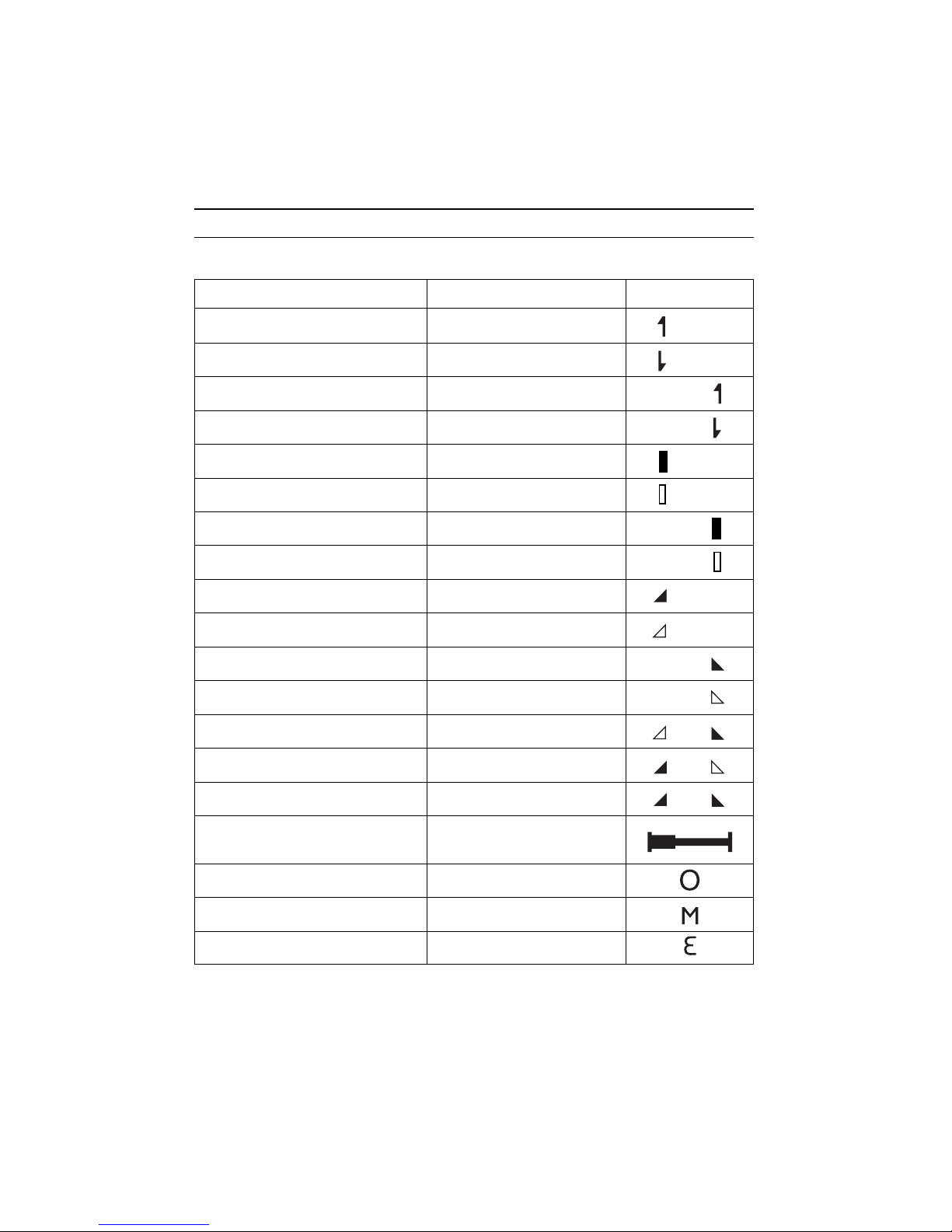
The display of the D1C controller uses the following symbols:
Description Comment Symbol
Limit value transgression Symbol
Relay 1, upper left
Symbol
Relay 1 lower left
Symbol
Relay 2 upper right
Symbol
Relay 2 lower right
Metering pump 1 (Increase conductivity) Symbol
Control OFF left
Symbol
Control ON left
Metering pump 2 (Reduce conductivity) Symbol
Control OFF right
Symbol
Control ON right
Solenoid valve 1 (Increase conductivity) Symbol
Control OFF left
Symbol
Control ON left
Solenoid valve 2 (Reduce conductivity) Symbol
Control OFF right
Symbol
Control ON right
Servomotor
Control, open relay
Control, close relay
Without control
Thickness of bar
Position feedback increases from left to right
during opening
Stop button pressed
Manual metering
Fault
5 Display Symbols
Page 7
7
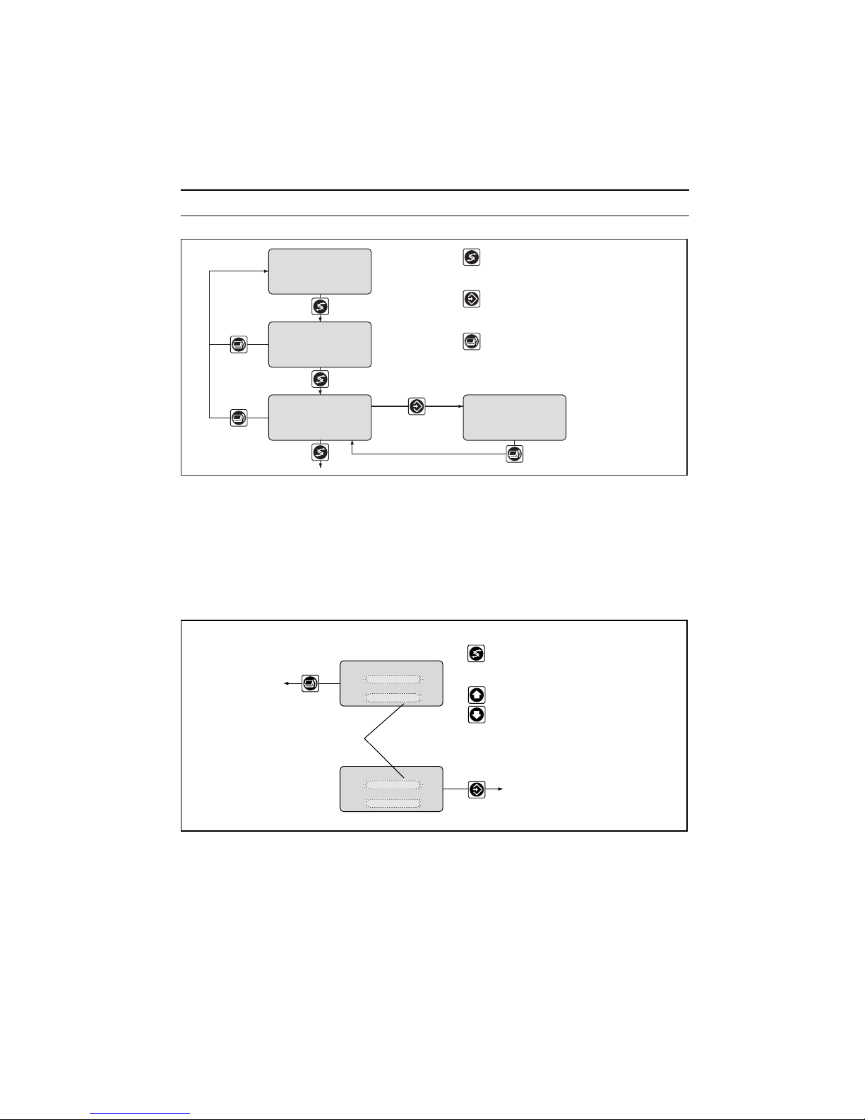
D1C2-Leit.-007-GB
Access code, correct
Parameter
setting
Permanent
display 1
Permanent
display 2
Various
Access code
Setting menus
The various menus are selected with
the CHANGE button
The menu is started with
the ENTER button
BRANCH BACK to permanent display
or to relevant setting menu
NOTE
Access to the setting menus can be barred with the access code!
The number and scope of setting menus is dependent on the device version!
If the access code is selected correctly in a setting menu, then the following setting menus are also
accessible!
If within a period of 10 minutes no button is pushed, the unit automatically branches back from the
calibrating menu or a setting menu to the permanent display 1.
6 Operation
CHANGE from selection to selection
Change numbers or
settings of selection
Variables flash
ENTER and save setting,
continue to next menu
BRANCH BACK without
saving setting
BRANCH BACK to
start of setting
Text 1
Text 2
Selection 1
Selection 2
Text 1
Text 2
Selection 1
Selection 2
D1C2-Leit.-008-GB
Page 8
8
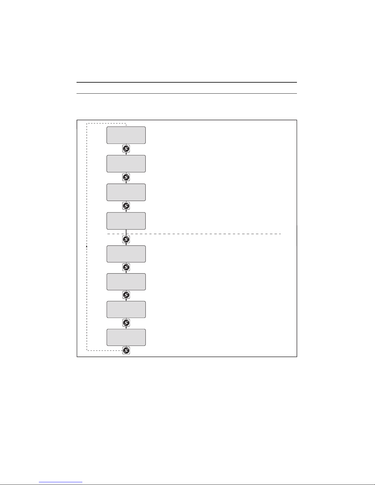
7 Restricted Operating Menu / Overview
The restricted operating menu permits simple operation of the most important parameters. The following
overview shows the settings which can be selected:
D1C2-Leit.-009-GB
Permanent display 1
Only with
solenoid valve relays
Only with control
Number and scope of setting menus
is dependent on the device
Access to setting menus can
be blocked with access code
µS/cm
100
calibration
conductivity ?
Only with connection on standard signal terminal
meas. parameter
setting ?
Only with connection on conductive conductivity terminal
relay
setting ?
control
setting ?
general setting
information
limits
setting ?
100 µS/cm
w: 1000 µS/cm
70 %
59 %
mea val.
Permanent display 2
only with control
(w=setpoint)
fd. fwd.:
reg. val.:
Page 9

9
D1C2-Leit.-010-GB
Permanent display 1
100 µS/cm
w: 1000 µS/cm
70 %
59 %
µS/cm
100
SV1 cond
SV2 cond
1000 µS/cm
1000 s
Ti =
Td =
xp =
0 s
10 %
xp =
10 %
30 %
15 %
DxLxxxxxxxxxx
D1C-xx FW-xx.x
=
=
5000
Increase conductivity
Reduce conductivity
➞
➞
1000 µS/cm
1500 µS/cm
➞
➞
1500 µS/cm
1000 µS/cm
mea val.
Permanent display 2
only with control
(w=setpoint)
fd. fwd.:
reg. val.:
Positive values of setting variable:
Negative values of setting variable:
relay
setting ?
relay adjustment
relay1:
relay2:
control
Solenoid valves: SV1
SV2
limit 1
lower
limit 2
upper
limits
setting ?
control
settings ?
Only with control
control
positive cond
regulated value:
negative cond
control
current regulat.
value:
normal
30 %
control
current regulat.
value:
with dead zone
30 %
control
current regulat.
value:
manual
Control with dead zone
For normal control
PID control
Proportional control
setpoint
setpoint 2 upper
ctrl. parameter
setpoint 1 lower
ctrl. parameter
manual dosing
regulated range
general setting
information
ident-code: D1CA
software version
alarm relay access c.:
operating menu:
active
english
restricted
Only with connection on standard signal terminal
Only with connection on conductive conductivity terminal
1500 µS/cm
mr = meas. range
cc = cellconstant.
2000 µS/cm
cc :
1.000/cm
mr :
1006 µS/cm 25.0 °C
calibration
conductivity ?
calibration
conductivity:
meas. parameter
setting ?
Restricted Operating Menu / Layout
Page 10

10
D1C2-Leit.-029-GB
1500 µS/cm
calibration
conductivity ?
calibration
conductivity:
D1C2-Leit.-011-GB
Permanent display 1
Permanent display 2
only with control
(w = setpoint)
Positive values of setting variable:
Negative values of setting variable:
100
Increase conductivity
Reduce conductivity
mea val.
fd. fwd.
reg. val.
59 %
70 %
w:
µS/cm
100 µS/cm
1000 µS/cm
During calibration, metering is reduced to the set basic capacity. The standard signal of the output
(measured value/correction value) is frozen.
The actually measured value will be proposed; this value is adjustable. On successful completion of
calibration, all error checks which refer to the measured value are restarted.
Restricted Operating Menu / Description
Calibration conductivity with connection on standard signal
Calibration conductivity with connection on conductive conductivity terminals
Measuring parameter
2000 µS/cm
1538 µS/cm 23.8 °C
D1C2-Leit.-030-GB
Access to all setting menus can be blocked with an access code !
mr = meas. range
cc = cellconstant.
cc :
mr :
meas. parameter
setting ?
1.120/cm
Error message Condition effect Remarks
measured value too low value < 2 % check measuring range
value > xx mS/cm of
check measuring range measuring range
measured value too high value > 100 % check measuring range
value < xx mS/cm of
check measuring range measuring range
Possible values
Initial value Increment Lower value Upper value
Calibration conductivity measured value as per measuring range as per measuring range as per measuring range
Page 11

11
Relays for Solenoid Valve Activation
Restricted Operating Menu / Description
D1C2-Leit.-013-GB
Access to all setting menus can be blocked with an access code !
Only with relay activation
SV1 cond
SV2 cond
➞
➞
Relay
setting ?
Relay adjustment
Relay1:
Relay2:
Control cond.
Solenoid valves: SV1
SV2
D1C2-Leit.-014-GB
1000 µS/cm
1500 µS/cm
Access to all setting menus can be blocked with an access code !
Limit 1
lower
Limit 2
upper
Limits
setting ?
Limits
The measured value can be adjusted to the actual conductivity value by changing the cell constants.
The following menus apply generally!
Possible values
Initial value Increment Lower value Upper value Remarks
Cellconstant cc 1.000/cm 0.0001/cm 0.0060/cm 0.1499/cm cc can be adjusted
0.001/cm 0.150/cm 1.499/cm for all mr
0.01/cm 1.50/cm 12.00/cm over the complete area
Possible values
Initial value Increment Lower value Upper value Remarks
Relay adjustment as per identity solenoid value
code limit value
off
Page 12

12
Restricted Operating Menu / Description
Control
D1C2-Leit.-015-GB
1000 s
Ti =
Td =
xp =
0 s
10 %
xp =
10 %
30 %
15 %
1000 µS/cm
1500 µS/cm
1000 µS/cm
Access to all setting menus can be blocked with an access code !
Only with control
Note: The controlled variable is recalculated every second. Only
suitable for processes with time constants greater than 30 s !
Increase conductivity
Reduce conductivity
Positive values of setting variable:
Negative values of setting variable:
➞
➞
control
settings ?
control
positive cond
regulated value:
negative cond
control
current regulat.
value:
normal
Control with dead zone
For normal control
PID control
Proportional control
setpoint
setpoint 2 upper
ctrl. parameter
setpoint 1 lower
ctrl. parameter
manual dosing
regulated range
control
current regulat.
value:
30 %
with dead zone
control
current regulat.
value:
30 %
manual
Initial value Increment Lower value Upper value Remarks
Type of limit Limit 1: lower lower
transgression Limit 2: upper upper
off
2)
Limit value Limit 1: 10 µS/cm 0.01 µS/cm –1 µS/cm 21 µS/cm meas. range 20 µS/cm
Limit 2: 15 µS/cm
Limit 1: 25 µS/cm 0.01 µS/cm –2.5 µS/cm 52.5 µS/cm meas. range 50 µS/cm*
Limit 2: 37.5 µS/cm
Limit 1: 100 µS/cm 0.1 µS/cm –10 µS/cm 210 µS/cm meas. range 200 µS/cm
Limit 2: 150 mS/cm
Limit 1: 250 µS/cm 0.1 µS/cm –25 µS/cm 525 µS/cm meas. range 500 µS/cm*
Limit 2: 375 µS/cm
Limit 1: 1000 µS/cm 1 µS/cm -100 µS/cm 2100 µS/cm meas. range 2000 µS/cm
Limit 2: 1500 µS/cm
Limit 1: 2500 µS/cm 1 µS/cm -250 µS/cm 5250 µS/cm meas. range 5000 µS/cm*
Limit 2: 3750 µS/cm
Limit 1: 10 mS/cm 0.01 mS/cm -1 mS/cm 21 mS/cm meas. range 20 mS/cm
Limit 2: 15 mS/cm
Limit 1: 100 mS/cm 0.1 mS/cm -10 mS/cm 210 mS/cm meas. range 200 mS/cm
Limit 2: 150 mS/cm
Limit 1: 500 mS/cm 1 mS/cm -50 mS/cm 1050 mS/cm meas. range 1000 mS/cm*
Limit 2: 750 mS/cm
* = only with connection on standard signal
2)
= only with limit value relay
Page 13

13
Restricted Operating Menu / Description
Possible values
Initial value Increment Lower value Upper value Remarks
Setpoint 10 µS/cm 0.01 µS/cm -1 µS/cm 21 µS/cm meas. range 20 µS/cm
15 µS/cm 0.01 µS/cm -2.5 µ/Sm 52.5 µ/Scm meas. range 50 µS/cm*
100 mS/cm 0.1 mS/cm -10 µS/cm 210 µS/cm meas. range 200 µS/cm
250 µS/cm 0.1 µS/cm -25 µS/cm 525 µS/cm meas. range 500 µS/cm*
1000 µS/cm 1 µS/cm -100 µ/Scm 2100 µ/Scm meas. range 2000 µ/Scm
2500 µS/cm 1 µS/cm -250 µS/cm 5250 µS/cm meas. range 5000 µS/cm*
10 mS/cm 0.01 mS/cm -1 mS/cm 21 mS/cm meas. range 20 mS/cm
100 mS/cm 0.1 mS/cm -10 mS/cm 210 mS/cm meas. range 200 mS/cm
500 mS/cm 1 mS/cm -50 mS/cm 1050 mS/cm meas. range 1000 mS/cm*
2 setpoints necessary
for control with dead zone.
setpoint 1 < setpoint 2
adjustment of measuring range
on page 18
Control parameter xp 10 % 1 % 1 % 500 % xp referred to measuring range
Control parameter Tn off 1 s 1 s 9999 s function off = 0 s
Control parameter Tv off 1 s 1 s 2500 s function off = 0 s
Manual metering 0 % 1 % –100 % +100 %
* = only with connection on standard signal
General Settings
D1C2-Leit.-016-GB
DxLxxxxxxxxxx
D1C-xx FW-xx.x
=
=
5000
general setting
information
ident-code: D1CA
software version
alarm relay access c.:
operating menu:
active
english
restricted
Access to all setting menus can be blocked with an access code !
Possible values
Initial value Increment Lower value Upper value Remarks
Alarm relay active active
not active
Access code 5000 1 1 9999
Language as per identy code
Operating menu restricted restricted
complete
Page 14

14
Complete Operating Menu / Overview
All parameters of the controller can be set in the complete operating menu. The following overview shows
the settings which can be selected:
D1C2-Leit.-017-GB
Number and scope of setting menus
is dependent on the device
Access to setting menus can
be blocked with access code
mea val.:
Only with servomotor
Only with feed forward
Only with 2 standard
signal outputs
Only with 2 standard
signal outputs
Only with standard
signal output
fd. fwd.:
reg. val.:
100 µS/cm
w: 1000 µS/cm
70 %
-59 %
µS/cm
100
meas. parameter
setting ?
pumps
setting ?
relays
setting ?
limits
setting ?
servomotor
setting ?
feed forward ctrl.
setting ?
signal output 1
mA setting ?
general setting
information
Connection terminal conductive conductivity
Connection terminal standard signal
Only with control
control
setting ?
signal output 2
mA setting ?
calibration
α
Only with
servomotor
Only with
feed forward
Only with standard
signal output
100 µS/cm
w: 1000 µS/cm
70 %
-59 %
µS/cm
100
meas. range cond.
setting ?
pumps
setting ?
relays
setting ?
limits
setting ?
servomotor
setting ?
feed forward ctrl.
setting ?
signal output 1
general setting
information
Only with control
control
setting ?
measured value
setting ?
calibration
conductivity ?
change type of
connection ?
correction value
setting ?
cc :
α :
1.080/cm
2.10 %/°C
mA setting ?
signal output 2
mA setting ?
Permanent display 1 Permanent display 1
Permanent display 2
only with control
(w = setpoint)
Permanent display 2
only with control
(w = setpoint)
Only with solenoid
valve relay
Only with solenoid
valve relay
Only with pumps
Only with correction value
Only with pumps
mea val.:
fd. fwd.:
reg. val.:
Page 15

15
Complete Operating Menu / Description
D1C2-Leit.-018-GB
w:
70 %
59 %
100 µS/cm
1000 µS/cm
µS/cm
100
Permanent display 1
Increase conductivity
Reduce conductivity
mea val.
Permanent display 2
only with control
(w = setpoint)
fd. fwd.:
reg. val.:
Positive values of setting variable:
Negative values of setting variable:
setting ?
meas. parameter
D1C2-Leit.-036-GB
Access to all setting menus can be blocked with an access code !
mr = meas. range
cc = cellconstant. cc :
mr :
1006 µS/cm 25.0 °C
2000 µS/cm
1.000/cm
α :
coefficient
α = temperature-
1.90%/ °C
With connection on standard signal see page 19
With connection on conductive conductivity terminals:
Measuring parameter
Possible values
Initial value Increment Lower value Upper value Remarks
Measuring range mr 0....2000 µS/cm 0....20 µS/cm setpoints and limit
0....200 µS/cm values are switched
0....2000 µS/cm to the corresponding
0....20 mS/cm startup values
0....200 mS/cm
Cellconstant cc 1000 /cm 0.0001/cm 0.0060/cm 0.1499/cm cc can be adjusted
0.001/cm 0.150/cm 1.499/cm for all mr
0.01/cm 1.50/cm 12.00/cm over the complete area
Temperature-coefficient
α 1.90 %/°C 0.01 %/°C0 %/°C 10 %/°C
The measured value can be adjusted to the actual conductivity value by changing the cell constants.
Prerequisite is a known temperature coefficient and a constant temperature.
When changing the measuring range, metering and control are stopped, the setpoints, limit values, and the
standard signal output are set to the corresponding startup values! Check these settings in all menus!
Page 16

16
Complete Operating Menu / Description
Calibrating temperature coefficient α
The temperature coefficient is a determined through two-output calibration. During the calibration procedure,
metering is reduced to the set basic load. The monitoring of limiting values and error treatment are stopped.
The standard signal of the output measured value or correction value is reduced to 0/4 mA.
ATTENTION:
The conductivity values you enter must base on 25 °C. You must use the same solution when
calibrating both temperatures!
D1C2-Leit.-032-GB
Access to all setting menus can be blocked with an access code !
calibration at
probe in buffer !
temperature 1
1006 25.0 °C
calibration at
probe in buffer !
temperature 2
1006 25.0 °C
permanent display 1
calibration α ?
cc :
α :
1.000/cm
1.90 %/°C
calibration α
cc :
α :
1.080/cm
2.52 %/°C
calibration at
accept value ?
temperature 1
1006 25.0 °C
calibration at
accept value ?
temperature 2
1006 25.0 °C
calibration
temp1:
value:
temp2:
35.0 °C
25,0 °C
1006
calibration
temp1:
value:
1006
25.0 °C
Possible values
Initial value Increment Lower value Upper value Measuring range
Set sample measuring value 0.01 µS/cm - 1 µS/cm 21 µS/cm 20 µS/cm
0.1 µS/cm - 10 µS/cm 210 µS/cm 200 µS/cm
1 µS/cm - 100 µS/cm 2100 µS/cm 2000 µS/cm
0.01 mS/cm - 1 mS/cm 21 mS/cm 20 mS/cm
0.1 mS/cm - 10 mS/cm 210 mS/cm 200 mS/cm
Set temperature correction value 0.1 °C0 °C 100 °C
Error message Condition Remarks
temperature range restricted For the chosen temperature
xx – 100 °C coefficient a, a correct reading
can only be obtained for the
displayed temperature range.
temperature distance wrong ∆ temperature ≥ 10.0 °C
∆ temperature ≤ 50.0 °C
Page 17

17
Complete Operating Menu / Description
D1C2-Leit.-033-GB
Access to all setting menus can be blocked with an access code !
cell connection wire resistance
resistance !
connect final
final resistance
wire resistance
change type of
connection ?
2-wire automatic
cell connection
wire resistance
4-wire
manual
10.0 Ω
3.7 Ω
3.7 Ω
D1C2-Leit.-034-GB
Access to all setting menus can be blocked with an access code !
automatic
correction value correction value
calibration temp.
33.0 °C
setting ?
Cell connection
Initial value Increment Lower value Upper value
Cell connection 2-wire 2-wire
4-wire
Determine wire resistance manual manual
automatic
Manual entry wire resistance 0.5 Ω 0.1 Ω 0 Ω 50 Ω
Final resistance 10.0 Ω 0.1 Ω 10 Ω 50 Ω
Correction value (only with connection on conductive conductivity terminals)
Possible values
Initial value Increment Lower value Upper value
Temperature compensation as per manual
category identity code automatic
off
Manual temperature 25 °C0.1 °C0 °C 100 °C
Automatic temperature correction value 0.1 °C0 °C 100 °C
Page 18

18
Possible values
Initial value Increment Lower value Upper value
Calibration conductivity measured value as per measuring range as per measuring range as per measuring range
Measuring range
Complete Operating Menu / Description
Calibration conductivity with connection standard signal
D1C2-Leit.-029-GB
1500 µS/cm
calibration
conductivity ?
calibration
conductivity:
Meas. range cond.
D1C2-Leit.-019-GB
0…2000 µS/cm
Access to all setting menus can be blocked with an access code !
Meas. range
setting ?
During calibration, metering is reduced to the set basic capacity. The standard signal of the output
(measured value/correction value) is reduced to 0 mA or 4 mA.
The actually measured value will be proposed; this value is adjustable. On successful completion of
calibration, all error checks which refer to the measured value are restarted.
Error message Condition effect Remarks
measured value too low value < 2 % check measuring range
value > xx mS/cm of
check measuring range measuring range
measured value too high value > 100 % check measuring range
value < xx mS/cm of
check measuring range measuring range
When changing the measuring range, setpoints and limit values are switched over to their respective initial
values. The settings must be checked in all menus!
Page 19

19
When changing the range adjustment, the adjustments in all menus have to be checked!
D1C2-Leit.-020-GB
4 mA
= 0 µS/cm
20 mA =
2000 µS/cm
Access to all setting menus can be blocked with an access code !
Standard signal input mA
Measured value
range adjustment
Measured value
range adjustment
Measured value
Checkout time
Measured value
off
Meas. value
setting ?
Complete Operating Menu / Description
Measured value
Possible values
Initial value Increment Lower value Upper value Remarks
Standard signal input 4 mA 0 mA
lower signal limit 4 mA
Allocated
special voltage 0–2000 µS/cm depending on –5 % +5 %
measuring range of final value of final value
Checkout time off 1 s 1 s 9999 s Constant measurement signal
results in message and alarm.
Function off = 0 s
Possible values
Initial value Increment Lower value Upper value Remarks
Measuring range 0....2000 µS/cm 0....1000 mS/cm* setpoints and limit values
0....200 mS/cm are switched over
0....20 mS/cm to their respective
0....5000 µS/cm* initial values
0....2000 µS/cm
0....500 µS/cm* * only with connection
0....200 µS/cm on standard signal
0....50 µS/cm*
0....20 µS/cm
Page 20

20
D1C2-Leit.-023-GB
10 s
1 s
10 s
1 s
➞
➞
➞
➞
Access to all setting menus can be blocked with an access code !
Only with relay activation
Relays
setting ?
Solenoid valve 2
cond
Solenoid valve 1
cond
period
min. time
period
min. time
Relay adjustment
Relay1:
Relay2:
Control cond.
Solenoid valves: SV1
SV2
SV1 cond
SV2 cond
Complete Operating Menu / Description
D1C2-Leit.-022-GB
120
120
➞
➞
Access to all setting menus can be blocked with an access code !
Only with pumps for control
Pumps
setting ?
Dosing pump max.
pump1:
pump2:
Control
pump1 cond
pump2 cond
pulse/minute
The following menus apply generally
Pumps
Possible values
Initial value Increment Lower value Upper value Remarks
Max. stroke/minute of 120 1 1 500 off = 0 strokes/min
pumps 1 and 2
Relay for solenoid valve activation
Possible values
Initial value Increment Lower value Upper value Remarks
Relay adjustment as per solenoid valve
identity code limit
off
Period 10 s 1 s 10 s 9999 s
Min. time 1 s 1 s 1 s period/2
Page 21

21
Possible values
Initial value Increment Lower value Upper value Remarks
Type of limit Limit 1: lower upper limit transgression
transgression Limit 2: upper lower when exceeding or
off 2) dropping below value
Limit 1; Limit 2 500; 750 mS/cm 1 mS/cm –50 mS/cm 1050 mS/cm meas. range 1000 ms/cm*
100; 150 mS/cm 0.1 mS/cm –10 mS/cm 210 mS/cm meas. range 200 ms/cm
10; 15 mS/cm 0.01 mS/cm –1 mS/cm 21 mS/cm meas. range 20 ms/cm
2500; 3750 µS/cm 1 µS/cm –250 µS/cm 5250 µS/cm meas. range 5000 µs/cm*
1000; 1500 µS/cm 1 µS/cm –100 µS/cm 2100 µS/cm meas. range 2000 µs/cm
250; 375 µS/cm 0.1 µS/cm –25 µS/cm 525 µS/cm meas. range 500 µs/cm*
100; 150 µS/cm 0.1 µS/cm –10 µS/cm 210 µS/cm meas. range 200 µs/cm
25; 37 µS/cm 0.01 µS/cm –2.5 µS/cm 52.5 µS/cm meas. range 50 µs/cm*
10; 15 µS/cm 0.01 µS/cm –1 µS/cm 21 µS/cm meas. range 20 µs/cm
Switch-on delay 0 s 1 s 0 s 9999 s only with complete
Limit 1; Limit 2 operating menu
Switch-off delay 0 s 1 s 0 s 9999 s only with complete
Limit 1; Limit 2 operating menu
Max. on time off 1 s 0 s/off 9999 s only with complete
Limit 1; Limit 2 operating menu
function can be switched off
Hysteresis limits 5 mS/cm* 1 mS/cm –2 mS/cm 1050 mS/cm Effective in direction
1 mS/cm 0.1 mS/cm –0.4 mS/cm 210 mS/cm of "cancelling
0.1 mS/cm 0.01 mS/cm –0.04 mS/cm 21 mS/cm limit transgression"
25 µS/cm* 1 µS/cm –10 µS/cm 5250 µS/cm
10 µS/cm 1 µS/cm –4 µS/cm 2100 µS/cm
2.5 µS/cm* 0.1 µS/cm –1 µS/cm 525 µS/cm
1.0 µS/cm 0.1 µS/cm –0.4 µS/cm 210 µS/cm
0.25 µS/cm* 0.01 µS/cm –0.1 µS/cm 52.5 µS/cm
0.10 µS/cm 0.01 µS/cm –0.04 µS/cm 21 µS/cm
Checkout time limits off 1 s 1 s/off 9999 s function can be switched off
* = only with connection on standard signal, 2) = only with limit value relay
D1C2-Leit.-024-GB
1 s
1 s
1 s
1 s
300 s
10 µS/cm
time:
0 s
time:
1000 µS/cm
1500 µS/cm
1500 µS/cm
1000 µS/cm
max.
max.
0 s
Access to all setting menus can be blocked with an access code !
Only with limit value relay
Limit 1
lower
Limit 1
Limit 1
lower
∆t on
∆t off
Limit 2
upper
Limit 2
Limit 2
upper
∆t on
∆t off
Hysteresis
limits:
Checkout time
limits:
Limits
setting ?
Complete Operating Menu / Description
Limits
Page 22

22
Access to all setting menus can be blocked with an access code !
Servomotor
setting ?
Dosing:
Control range:
0 % to
operating range
100 %
Only with
Servomotor
Servomotor
Current position:
Servomotor
open ?
Servomotor
Please wait !
open
Servomotor
Please wait !
close
Servomotor
Value take over ?
opened !
Servomotor
Value take over ?
closed !
Servomotor
close ?
Servomotor
Current position:
OK
= automatic timing
D1C2-Leit.-025-GB
cond
➞
setting
Servomotor
Activation of the servomotor must be carried out with the same meticulous care as taken when calibrating
a measuring probe. The operating range is defined by the total resistance range of the feedback
potentiometer. The maximum limit of the range actually used is set by defining the control range.
ATTENTION:
To ensure correct operation, the activation time of the actuator used should not be less than
25 seconds for the control range from 0…100 %!
Complete Operating Menu / Description
Possible values
Initial value Increment Lower value Upper value Remarks
Servomotor setting setting
ok
off
Control direction cond. cond.
cond.
Control range 100 % 1 % 10 % 100 % in % of
operating range
Page 23

23
D1C2-Leit.-026-GB
10 %
1000 s
Ti =
Td =
xp =
0 s
10 %
xp =
10 %
30 %
15 %
1000 µS/cm
1500 µS/cm
1000 µS/cm
additional load:
regulated range
Access to all setting menus can be blocked with an access code !
Only with control
Note: The controlled variable is recalculated every second. Only
suitable for process with time constants greater than 30 s !
Control with dead zone
For normal control
PID control
Proportional control
setpoint
setpoint 2 upper
ctrl. parameter
setpoint 1 lower
ctrl. parameter
control
settings ?
control cond.
regulated value:
manual dosing
control
current regulat.
value:
regulated range
normal
➞
➞
positive cond
negative cond
Increase conductivity
Reduce conductivity
Positive values of setting variable:
Negative values of setting variable:
Control
Possible values
Initial value Increment Lower value Upper value Remarks
Control normal normal When controlling with dead
with dead zone zone, the feed forward control
manual is not used for measured values
within the dead zone
Setpoint 500 mS/cm 1 mS/cm –50 mS/cm 1050 mS/cm meas. range 1000 mS/cm*
100 mS/cm 0.1 mS/cm –10 mS/cm 210 mS/cm meas. range 200 mS/cm
10 mS/cm 0.01 mS/cm –1 mS/cm 21 mS/cm meas. range 20 mS/cm
2500 µS/cm 1 µS/cm –250 µS/cm 5250 µS/cm meas. range 5000 µS/cm*
1000 µS/cm 1 µS/cm –100 µS/cm 2100 µS/cm meas. range 2000 µS/cm
250 µS/cm 0.1 µS/cm –25 µS/cm 525 µS/cm meas. range 500 µS/cm*
100 µS/cm 0.1 µS/cm –10 µS/cm 210 µS/cm meas. range 200 µS/cm
15 µS/cm 0.01 µS/cm –2.5 µS/cm 52.5 µS/cm meas. range 50 µS/cm*
10µS/cm 0.01 µS/cm –1 µS/cm 21 µS/cm meas. range 20 µS/cm
setpoint 2 ≥ setpoint 1
Control parameter xp 10 % 1 % 1 % 500 % xp referred to measuring range
Control parameter Ti off 1 s 1 s 9999 s function off = 0 s
Control parameter Td off 1 s 1 s 2500 s function off = 0 s
Additional load 0 % 1 % –100 % +100 %
Manual metering 0 % 1 % –100 % +100 %
*only with connection on standard signal
Complete Operating Menu / Description
Page 24

24
Complete Operating Menu / Description
Feed forward control
Standard signal output 1
D1C2-Leit.-035-GB
feed forward ctrl.
setting ?
max. additive
feed forward ctrl.
regulated value
10.00 Hz
effect:
feed forward ctrl.
additiv
100 %
Hz / mA
10 Hz
feed forward ctrl.:
rated value:
feed forward
control:
Possible values
Initial value Increment Lower value Upper value Remarks
Feed forward control (Flow) as per identity code None signal processing:
10 Hz signal <0.02 Hz = no flow
500 Hz signal <0.2 Hz = no flow
with standard signal:
0…20 mA signal <0.2 mA = no flow
4–20 mA 4…20 mA signal <4.2 mA = no flow
Feed forward control 10 Hz 0.01 Hz 0.1 Hz 10 Hz Depended on signal type.
rated value 500 Hz 1 Hz 5 Hz 500 Hz Maximum limitation
20 mA 0.01 mA 0/4 mA 20 mA of range used.
Feed forward control effect multiplicative multiplicative
additive
Max. add. regulated value 100 % 1 % –500 % +500 % only with add.
feed forward control
D1C2-Leit.-027-GB
0…20 mA
2000 µS/cm
0 mA =
20 mA =
0%
0 mA =
20 mA =
100%
0 µS/cm
➞
➞
positive cond
negative cond
Access to all setting menus can be blocked with an access code !
Control with standard signal
signal output 1
mA setting ?
Only with standard signal output
signal output 1
mA
control
regulated value:
signal output 1
regulated value
Measured value
signal output 1
measured value
signal output 1
100.0 °C
0 mA =
20 mA =
correction value
0.0 °C
Only with connection on conductive conductivity
terminal
Page 25

25
D1C2-Leit.-037-GB
0…20 mA
2000 µS/cm
0 mA =
20 mA =
0%
0 mA =
20 mA =
100%
0 µS/cm
➞
➞
positive cond
negative cond
Access to all setting menus can be blocked with an access code !
Control with standard signal
signal output 2
mA setting ?
Only with 2 standard signal outputs
signal output 2
mA
control
regulated value:
signal output 2
regulated value
Measured value
signal output 2
measured value
signal output 2
100.0 °C
0 mA =
20 mA =
correction value
0.0 °C
Only with connection on conductive conductivity
terminal
Standard signal output 2
Complete Operating Menu / Description
Possible values
Initial value Increment Lower value Upper value Remarks
Variable allocation as per measured value
identity code controlled variable If control applicable
correction value only with correction variable
Output range 0…20 mA 0…20 mA
4…20 mA
Range measured value 0–20 µS/cm 0.01 µS/cm –1 µS/cm 21 µS/cm meas. range 20 µS/cm
0–50 µS/cm 0.01 µS/cm –2.5 µS/cm 52.5 µS/cm meas. range 50 µS/cm*
0–200 µS/cm 0.1 µS/cm –10 µS/cm 210 µS/cm meas. range 200 µS/cm
0–500 µS/cm 0.1 µS/cm –25 µS/cm 525 µS/cm meas. range 500 µS/cm*
0–2000 µS/cm 1 µS/cm –100 µS/cm 2100 µS/cm meas. range 2000 µS/cm
0–5000 µS/cm 1 µS/cm –250 µS/cm 5250 µS/cm meas. ranges 5000 µS/cm*
0–20 mS/cm 0.01 mS/cm –1 mS/cm 21 mS/cm meas. range 20 mS/cm
0–200 mS/cm 0.1 mS/cm –10 mS/cm 210 mS/cm meas. range 200 mS/cm
0–1000 mS/cm 1 mS/cm –50 mS/cm 1050 mS/cm meas. range 1000 mS/cm*
Range controlled variable 0 %…+100 % 1 % –100 % +100 % minimum range 1 %
Range correction value 0....100 °C0.1 °C0.0 °C 100 °C minimum range 1 °C
*only with connection on standard signal
Page 26

26
General setting
Complete Operating Menu / Description
D1C2-Leit.-028-GB
DxLxxxxxxxxxx
D1C-xx FW-xx.x
5000
= alarm
=
=
off
Access to all setting menus can be blocked with an access code !
general setting
information
ident-code: D1CA
software version
alarm relay control input
= active
access c.:
operating menu:
active
closed
english
complete
pause
Possible values
Initial value Increment Lower value Upper value Remarks
Alarm relay active active
not active
Pause Pause Pause *If pause/hold is active the
Pause/Hold* last valid setting value
(PI-part) is frozen
Control input pause closed closed
open
Alarm pause off off Alarm relay can be
on triggered by pause contact
Access code 5000 1 1 9999
Language
as per identity code
Operating menu complete restricted
complete
* at software version 4.6
Hold function (all measurement variables)
When the pause/hold setting is selected, on activation, the controlled variable is frozen to the last value
(PI-part is retained). This setting can be carried out in the complete operating menu – general settings
information.
Page 27

27
9 EC Declaration of Conformity
Page 28

28
©1995 ProMinent Dosiertechnik GmbH · D-69123 Heidelberg
Operating Instructions DULCOMETER® D1C, Part 2/L, Version 1.0, Issue 08/01
Subject to modifications · Printed in the F.R.Germany
ProMinent Dosiertechnik GmbH · Im Schuhmachergewann 5-11 · 69123 Heidelberg · Germany
Postfach 101760 · 69007 Heidelberg · Germany
info@prominent.de · www.prominent.de
10 Troubleshooting
Fault Fault text Symbol Effect Alarm with Remarks Remedy
On metering On control
acknowledgement
Measured value mS-meas. range ↑↓ Basic load Stop Yes meas. value out Check range adjustment
Signal exceeds/drops below Check ms-input Basic load Stop Yes of meas. range. Check probe, transducer
value* Signal <3.0 ±0.2 mA and cable connection
or >23 ±0.2 mA
Checkout time meas. value exceeded* Check ms-probe Basic load Stop Yes Function defectable Check function of probe
Correction variable
Signal exceeds/drops below Check te-input Basic load Stop Yes Signal <3.0 ±0.2 mA Check probe, transducer
value* or >23 ±0.2 mA and cable connection
upper limit temperature exceeded te-limit ↑ Basic load Stop Yes α ≥ 4 %/°C
Feed forward control
Signal exceeds/drops below Check feed forward Yes Signal <3.0 ±0.2 mA Check probe, transducer
value* input or >23 ±0.2 mA and cable connection
Value last valid
is used
Limit transgression mS-limit 1 ↑↓ Yes Function defectable Define cause,
after checkout time limits mS-limit 2 ↑↓ reset values if necessary
Servomotor
Position not reached Servomotor defective Yes Servomotor closes Check servomotor
Electronics error System error Stop Stop Yes Electronic data defective Call in service
Operation Note text Symbol Effect Alarm with Remarks Remedy
On metering On control
acknowledgement
Pause contact Pause Stop Stop No No further –
fault check
Stop button Stop Stop Stop No Relay drops out –
Calibration*
Calibration mS-calibration Basic load Stop – – Repeat calibration
with error insufficient Check probe/buffer
During servomotor setting
Position feed back wrong Direction check Without correct Check connection of relay,
adjustment the last potentiometer
Upper position <40 % max. value Final value small valid values are still used Adjust the operation region
Lower position >30 % range Final value big of the servomotor correctly
*only with connection on standard signal
 Loading...