

Page 1
Assembly instructions
A0507
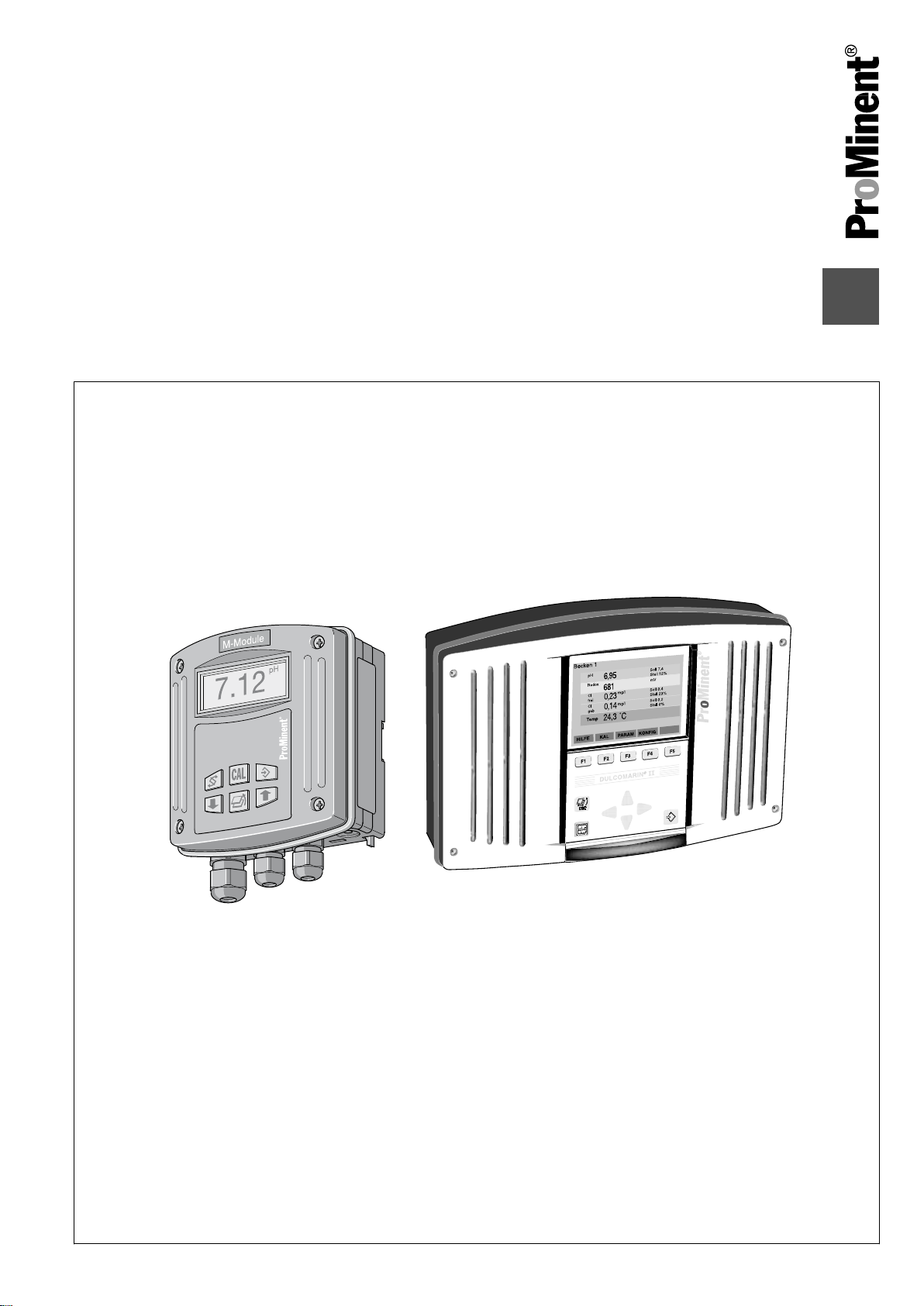
Multi-Channel Measuring and Control System
DULCOMARIN® II Swimming Pool Controller and
Disinfection Controller DXCa
Part 1: Assembly and installation
Please enter the identity code of your device here! DXCa _ _ _ _ _ _ _ _ _ _ _ _ _
Please carefully read these operating instructions before use! · Do not discard!
The operator shall be liable for any damage caused by installation or operating errors!
Technical changes reserved.
Part no. 986907 BA DC 080 04/12 EN
Page 2

ProMinent Dosiertechnik GmbH
Im Schuhmachergewann 5 - 11
69123 Heidelberg
Telephone: +49 6221 842-0
Fax: +49 6221 842-419
email: info@prominent.de
Internet: www.prominent.com
986907, 2, en_GB
© 2012
2
Page 3

Supplemental instructions
Further applicable documents
These operating instructions and supplementary instructions are
only valid in combination with the following operating and supple‐
mentary instructions:
n Multi-channel measuring and control system operating instruc‐
tions DULCOMARIN® II
, Swimming Pool Controller and Disin‐
fection Controller DXCa Part 2: Operation
n Supplementary instructions DULCOMARIN® II, Screen plotter
operation
n Supplementary instructions DULCOMARIN® II, M-Module
(measuring module for pH, redox [ORP], temperature) DXMaM
connection
n Supplementary instructions DULCOMARIN® II, A-Module (con‐
trol module, pump and standard signal outputs mA) DXMaA
n Supplementary instructions DULCOMARIN® II, N-Module
(power supply module without relay) DXMaN
n Supplementary instructions DULCOMARIN® II, P-Module
(power supply module with relay) DXMaP
n Supplementary instructions DULCOMARIN® II, I-Module (cur‐
rent input module, standard signal inputs mA) DXMal
3
Page 4

Table of contents
Table of contents
Device identification / identity code....................................... 5
1
2 Introduction........................................................................... 8
2.1 Explanation of the safety information............................ 8
2.2 Users' qualifications...................................................... 9
3 Safety and responsibility..................................................... 11
3.1 General safety information.......................................... 11
3.2 Correct and proper use............................................... 11
4 Planning aids and requirements for the installation site ..... 13
4.1 Requirements for the installation site.......................... 13
4.2 Determine the requirement for cables and accesso‐
ries.............................................................................. 14
4.3
Allocate power supply modules (DULCOMARIN® II
DULCO-Net)............................................................... 18
4.4 Routing the CAN bus backbone................................. 19
5 Assembly and installation................................................... 20
5.1 Procedure with DXC housing (large).......................... 20
5.1.1 Wall mounting.......................................................... 20
5.1.2 Control panel mounting............................................ 22
5.1.3 Installation (electrical).............................................. 23
5.1.4 Connect the coaxial cable........................................ 26
5.1.5 Connecting the terminals......................................... 26
5.2 Procedure with DXM housing (small)......................... 27
5.2.1 Mounting (mechanical)............................................ 27
5.2.2 Installation (electrical).............................................. 28
5.3 install the CAN bus cable............................................ 30
5.3.1 Connections outside the housing............................. 31
5.3.2 Connections inside the DXC housing...................... 34
6 Device overview and operating elements........................... 36
Functional description (general).......................................... 38
7
8 Maintenance, repairs and disposal..................................... 41
8.1 Disposal of used parts................................................ 42
9 Technical data spare parts and accessories....................... 43
10 EC Declaration of Conformity and fulfilled standards......... 44
11
Wiring diagram DULCOMARIN® II compact ...................... 45
12 Index................................................................................... 49
4
Page 5

1 Device identification / identity code
The identity code describes the DULCOMARIN® II,
compact controller
1)
The supplied cable is for connection to a hub, switch,
router or an intranet.
For direct connection of the DULCOMARIN® II to a PC/
MAC, the supplied LAN coupling and category 5 crossover cable are required.
The maximum LAN cable length is approximately 100
m.
To operate the web server on a PC we recommend
Microsoft® Internet Explorer 5 or higher as the
browser.
The scope of supply of the DXCa includes:
–
1 T-coupler
–
1 CAN connection cable
–
1 terminating resistance coupling and 1 terminating
resistance plug
–
1 SD memory card 64 MB or greater
–
1 card reader suitable for PCs
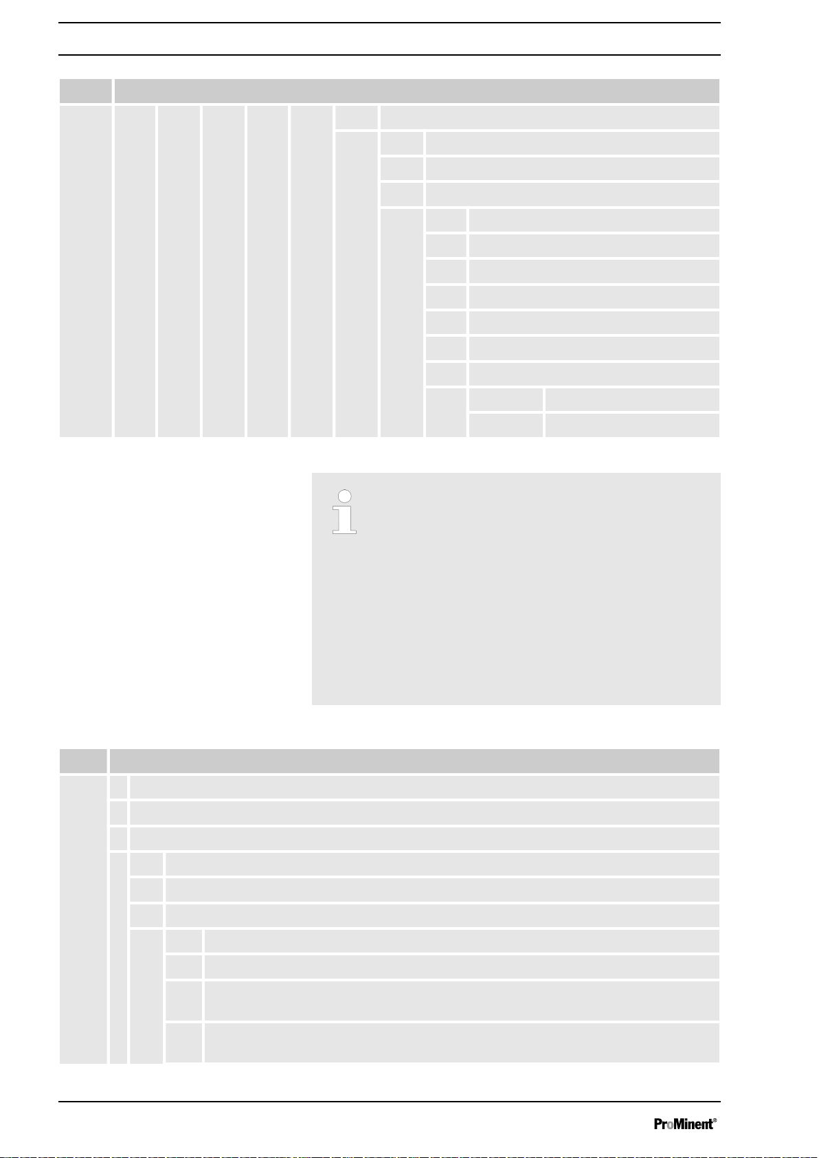
Device identification / identity code
DXCa
Multi-channel measuring and control system - DULCOMARIN
Mounting type:
W Wall mounted (IP 65)
S Control cabinet (IP 54)
Version:
0 With operating elements
D With operating elements for use in drinking water/disinfection applications
Communication interfaces:
0 none
5 Embedded Web-Server, LAN incl. 5 m LAN patch cable 1:1, LAN coupling,
6 OPC-Server + Embedded Web-Server, LAN incl. 5 m LAN patch cable 1:1,
Option:
® II Series DXC
5 m cross-over cable
LAN coupling, 5 m cross-over cable
1)
1)
1 Screen plotter with data logger incl. SD card and USB card reader
for PC
Module 1:
M M module, measuring module pH, redox, temperature
I I module, current input module, 3x mA, 0/4 ... 20 mA
Module 2:
0 not occupied
A A module, control module: 3 pumps and 4 analog out‐
puts
5
Page 6
Device identification / identity code
DXCa
Multi-channel measuring and control system - DULCOMARIN
® II Series DXC
I I module, current input module, 3x mA, 0/4 ... 20 mA
Application:
S Swimming Pools
D Disinfection, general
Preset language:
DE German
EN English
ES Spanish
FR French
IT Italian
PL Polish
Certification:
01 CE mark
DXCa
Multi-channel measuring and control system - DULCOMARIN
Mounting type:
W Wall mounted (IP 65)
S Control cabinet (IP 54)
Version:
0 With operating elements
The identity code describes the complete DULCO‐
MARIN® II DULCO® Net Central Unit.
If the central unit is populated with modules, then the
following applies:
Module 1 preferably as M module
Module 2 preferably allocated to the A module.
Module 3 must always be allocated to the P or N
module.
1)
Module 1 preferably as M module
2)
only in version: "2" without controls
® II Series DXC
2 Without operating elements
Communication interfaces:
0 none
5 Embedded Web-Server, LAN incl. 5 m LAN patch cable 1:1, LAN-coupling, 5 m
cross-over-cable
1)
6 OPC-Server + Embedded Web-Server, LAN incl. 5 m LAN patch cable 1:1, LAN-
coupling, 5 m cross-over-cable
1)
6
Page 7

DXCa
Multi-channel measuring and control system - DULCOMARIN
Option:
0
Without screen plotter
1 Screen plotter with data logger incl. SD card and USB card reader for PC
Module 1:
0 not occupied
M M module, measuring module pH, redox, temperature
A A module, control module: 3 pumps and 4 analog outputs
I I module, current input module, 3x mA, 0/4 ... 20 mA
Module 2:
0 not occupied
A A module, control module: 3 pumps and 4 analog outputs
M M module, measuring module: pH, redox, temperature
I I module, current input module, 3x mA, 0/4 ... 20 mA
Device identification / identity code
® II Series DXC
2)
Module 3:
0 not occupied
P P module, power supply, 1 alarm relay, 3 solenoid
valve relays
N N module, power supply without relay
A A module, control module: 3 pumps and 4 analog out‐
puts
M M module, measuring module: pH, redox, temperature
Application:
S Swimming Pools
D Disinfection, general
Preset language:
DE German
EN English
ES Spanish
FR French
IT Italian
PL Polish
Certification:
01 CE mark
7
Page 8
Introduction
2 Introduction
The operating instructions describe the technical data and func‐
tions of the multi-channel measuring and control system
DULCOMARIN®
troller DXCa. The operating instructions subsequently refer to the
system merely as DXCa.
2.1 Explanation of the safety information
II Swimming Pool Controller and Disinfection Con‐
Introduction
These operating instructions provide information on the technical
data and functions of the product. These operating instructions pro‐
vide detailed safety information and are provided as clear step-bystep instructions.
The safety information and notes are categorised according to the
following scheme. A number of different symbols are used to
denote different situations. The symbols shown here serve only as
examples.
DANGER!
Nature and source of the danger
Consequence: Fatal or very serious injuries.
Measure to be taken to avoid this danger
Danger!
–
Denotes an immediate threatening danger. If this is
disregarded, it will result in fatal or very serious
injuries.
WARNING!
Nature and source of the danger
Possible consequence: Fatal or very serious injuries.
Measure to be taken to avoid this danger
Warning!
Denotes a possibly hazardous situation. If this is
–
disregarded, it could result in fatal or very serious
injuries.
CAUTION!
Nature and source of the danger
Possible consequence: Slight or minor injuries, mate‐
rial damage.
Measure to be taken to avoid this danger
Caution!
Denotes a possibly hazardous situation. If this is
–
disregarded, it could result in slight or minor inju‐
ries. May also be used as a warning about material
damage.
8
Page 9
Introduction
NOTICE!
Nature and source of the danger
Damage to the product or its surroundings
Measure to be taken to avoid this danger
Note!
Denotes a possibly damaging situation. If this is
–
disregarded, the product or an object in its vicinity
could be damaged.
Type of information
Hints on use and additional information
Source of the information, additional measures
Information!
–
Denotes hints on use and other useful information.
It does not indicate a hazardous or damaging sit‐
uation.
2.2 Users' qualifications
WARNING!
Danger of injury with inadequately qualified personnel!
The operator of the plant / device is responsible for
ensuring that the qualifications are fulfilled.
If inadequately qualified personnel work on the unit or
loiter in the hazard zone of the unit, this could result in
dangers that could cause serious injuries and material
damage.
– All work on the unit should therefore only be con‐
ducted by qualified personnel.
–
Unqualified personnel should be kept away from
the hazard zone
Training Definition
Instructed personnel An instructed person is deemed to be a person who has been instructed and,
if required, trained in the tasks assigned to him/her and possible dangers that
could result from improper behaviour, as well as having been instructed in the
required protective equipment and protective measures.
Trained user A trained user is a person who fulfils the requirements made of an instructed
person and who has also received additional training specific to the system
from ProMinent or another authorised distribution partner.
Trained qualified per‐
sonnel
A qualified employee is deemed to be a person who is able to assess the
tasks assigned to him and recognize possible hazards based on his/her
training, knowledge and experience, as well as knowledge of pertinent regula‐
tions. The assessment of a person's technical training can also be based on
several years of work in the relevant field.
9
Page 10

Introduction
Training Definition
Electrician Electricians are deemed to be people, who are able to complete work on elec‐
trical systems and recognize and avoid possible hazards independently based
on his/her technical training and experience, as well as knowledge of pertinent
standards and regulations.
Electricians should be specifically trained for the working environment in
which the are employed and know the relevant standards and regulations.
Electricians must comply with the provisions of the applicable statutory direc‐
tives on accident prevention.
Customer Service depart‐
ment
Customer Service department refers to service technicians, who have
received proven training and have been authorised by ProMinent to work on
the system.
Note for the system operator
The pertinent accident prevention regulations, as well
as all other generally acknowledged safety regulations,
must be adhered to!
10
Page 11
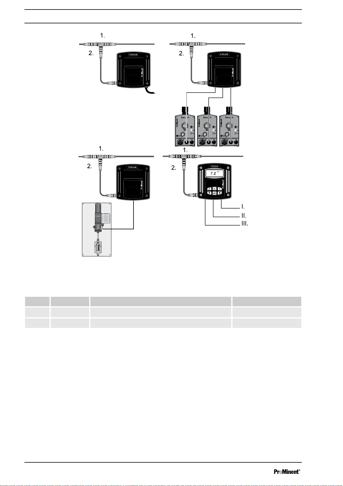
A0487
Planning aids and requirements for the installation site
Fig. 3: External modules DXMa
Accessories, supplied
Item. Quantity Description Part no.
1 1 T-coupler, M12,5-pole CAN 1022155
2 1 Connecting cable - CAN, M12, 5 pole 0.5 m 1022137
16
Page 12
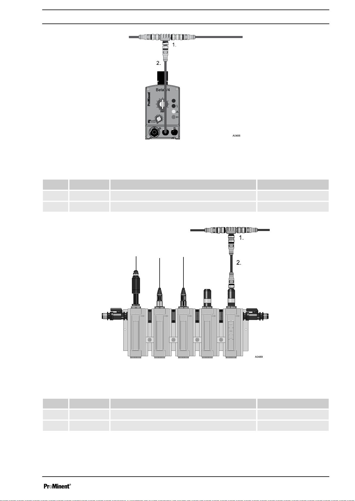
Planning aids and requirements for the installation site
Fig. 4: Beta/4 CANopen
Accessories, supplied
Item. Quantity Description Part no.
1 1 T-coupler, M12,5-pole CAN 1022155
2 1 Connecting cable - CAN, M12, 5 pole 1 m 1022139
Fig. 5: Sensors DXUa
Accessories, supplied
Item. Quantity Description Part no.
1 1 T-coupler, M12,5-pole CAN 1022155
2 1 Connecting cable - CAN, M12, 5 pole 0.5 m 1022137
17
Page 13
Planning aids and requirements for the installation site
1. Determine the requirement for power supply modules, see
Ä Chapter 4.3 ‘Allocate power supply modules (DULCO‐
MARIN® II DULCO-Net)’ on page 18
2. Determine the requirement for connection cables between
the external modules
3. Determine the requirement for holding clamps for the con‐
nection cables (ASV pipe clips, 16 mm, order no. 359904
4.3
Allocate power supply modules (DULCOMARIN® II DULCO-Net)
Determine the number of additionally required power supply mod‐
ules (N modules and P modules).
1. Ensure that for each power supply module there is a power
outlet
The distance between the power supply modules
should not exceed 50 m.
2. Distribute the power supply modules as uniformly as possible
over the CAN bus line.
3. With an A module with connected plotters: arrange one of the
power supply modules as close as possible to the A module
Locate the power supply module in
the CAN bus backbone (main line)
(DULCOMARIN® II DULCO-Net)
The central unit always contains a power supply module.
Number of pools Additional N- or P-mod‐
ules
1 - 9 4
2 - 10 5
3 1 11 5
4 2 12 6
5 2 13 6
6 3 14 7
7 3 15 7
Number of pools Additional N- or P-mod‐
ules
8 4 16 8
Divide the number of pools by
2)
‘2’
. If a remainder is obtained, round down: (Exception: number of pools =
18
Page 14

4.4 Routing the CAN bus backbone
Planning aids and requirements for the installation site
CAUTION!
Maximum backbone length
Possible consequence: Malfunctions.
– The maximum backbone length (without branching
cables) must be less than 400 m
CAUTION!
Maximum length of branching cables
Possible consequence: Malfunctions.
The T-pieces and connecting cables (branching
cables) enclosed with the modules (M-, A-, G-, N-, R-,
I- modules, CAN sensors and metering pumps with
CAN bus must be used.
Branching cables are the connections branching from
the CAN bus backbone to the modules.
The external modules can be placed in any sequence
along the CAN bus backbone. The operating instruc‐
tions show for example possible sequences of the
external modules.
Each CAN cable has a plug or coupling on each end
so that these can be coupled together in sequence to
create longer cables.
Rule
Arrange the external modules in groups for each pool.
First assemble and install the external modules and
their attachments. Only then should you connect the
external modules with the CAN bus backbone and with
each other via the the shortest route.
Description Part no.
Connecting cable - CAN, M12, 5 pole, 0.5 m 1022137
Connecting cable - CAN, M12, 5 pole, 1 m 1022139
Connecting cable - CAN, M12, 5 pole, 2 m 1022140
Connecting cable - CAN, M12, 5 pole, 5 m 1022141
Connecting cable - CAN sold by the metre 1022160
19
Page 15

A0490
Assembly and installation
5 Assembly and installation
Procedure with DXC housing (large)
5.1
The DXC housing is suitable for mounting on a wall or in a control
panel
5.1.1 Wall mounting
Mounting materials (contained in the scope of delivery)
n 1 x wall bracket
n 4 x PT screws 5 x 35 mm
n 4 x washers 5.3
n 4 x rawl plug Ø 8 mm, plastic
Wall mounting
Take the wall bracket out of the DXC housing
Fig. 6: Removing the wall bracket
1. Pull the two snap hooks (1) outwards
The wall brackets snaps slightly downwards.
ð
2. Push the wall bracket downwards (2) from the DXC housing
and fold (3) it out
3. Use the wall bracket as a drilling template to mark the posi‐
tions of four drill holes
4. Drill the holes: Ø 8 mm, d = 50 mm
20
Page 16

Page 17

5.1.2 Control panel mounting
CAUTION!
Thickness of the control panel
The control panel must be sufficiently thick to ensure
that after fitting it does not bend. With steel panels it
must be at least 2 mm thick; select plastic correspond‐
ingly thicker.
Only in this way can the IP 54 rating be attained.
When fitted, the DXC housing extends approx. 45 mm
from the control panel. A drilling template is enclosed.
Page 18

Assembly and installation
8. Remove the front part
9. Now break out the necessary threaded holes of the lower
series, see
Ä Chapter 5.1.3 ‘Installation (electrical)’
on page 23
10. Screw the back part to the control panel (using the supplied
PT screws)
11. Plug the ribbon cable back on
12. Move the front part into the
Now first electrically install the DULCOMARIN® II and
ð
‘park position’
then complete the control panel mounting.
13. Place the front part on the rear part of the DXC housing and
screw it in
14.
CAUTION!
Protection class IP 54
Once again check the seating of the seal. Pro‐
tection class IP 54 is only achieved if the control
panel mounting is correct.
5.1.3 Installation (electrical)
WARNING!
Failure of the circulating pumps
In the event that the circulating pump fails, it is not suf‐
ficient to use the sample water limit contact of the inline probe housing on its own in order to stop the con‐
trol for the corresponding pool (contact K1 of the M
module).
The pool controller must also be set to Pause using
the contact K2
‘Pause control ’
of the M module.
Suitable triggers are:
– the zero volt contact of the filter control
– the zero volt contact of the circulation pump's
motor protection switch
– a flow monitor in the circulation line
WARNING!
Safe operating status
Both hardware and software safety precautions must
be taken to ensure that the DULCOMARIN® II adopts a
safe operating status in the event of a fault. E.g. use
limit switches, mechanical locks, ...
During installation the device must not be electrically
live.
The installation must only be carried out by technically
trained personnel.
Observe the technical data in these instructions.
23
Page 19

A0494
Assembly and installation
NOTICE!
Cable strain relief
With control panel mounting, the cables must be
routed in a site-provided cable duct to ensure strain
relief.
1. Plan which threaded holes shall be broken out (mark the
desired threaded holes)
CAUTION!
When breaking open the threaded holes, avoid
pushing the screwdriver deep into the housing. Parts
inside the device could be damaged.
Fig. 10: Breaking out threaded holes
2. To break out the threaded holes, punch the slit in the middle
of the threaded holes using a screwdriver (tip width 3.5 - 4
mm, see Fig. 10) and lever the material out
3. De-burr the resulting edges
24
Page 20

A0495
1.
2.
3.
4.
5.
Assembly and installation
Fig. 11: Fitting the threaded cable glands
1. Blanking plug
2. Union nut
3. Multiple seal insert
4. Threaded cable gland
5. Lock nut
4. Screw in the appropriate threaded cable glands (4) using
suitable lock nuts (5) and tighten firmly
5. Insert multiple seal inserts (3) depending on the cable diam‐
eter being used
6. Guide the cables into the threaded cable glands
7.
Further steps are contained in
coaxial cable’ on page 26
the terminals’ on page 26
Ä Chapter 5.1.4 ‘Connect the
and
Ä Chapter 5.1.5 ‘Connecting
.
8. Tighten the union nuts (2) of the threaded cable glands so
that they are properly sealed
9. Place the front part on the rear part
10. Manually tighten the four housing screws
11.
CAUTION!
Protection class IP 54
Once again check the seating of the seal. Pro‐
tection class IP 54 is only achieved if the control
panel mounting is correct.
25
Page 21

A0496
A0508
Assembly and installation
5.1.4 Connect the coaxial cable
The pH or redox sensor is connected
using a coaxial cable
Fig. 12: Removing the cable insulation
5.1.5
Connecting the terminals
1. Uncover the cable shielding according to
2. Tightly clamp the shielding
The wiring diagram is contained in the appendix.
Additionally there is an info field on the modules adja‐
cent to the terminals containing connection informa‐
tion.
Fig. 12
Fig. 13: Removing the cable insulation
1. Remove the insulation from the fork ends according to
Fig. 13 and press on the corresponding cable end sleeves
2. Pull off the terminal blocks P1 to P4 for installation
3. To fit the cable, push the supplied screwdriver right into the
square opening of the corresponding terminal in order to plug
the cable end into the terminal block
4. Connect the cables according to the wiring diagram
5. Push the pulled-off terminal blocks back onto the circuit
board after connecting the cables
26
Page 22

5.2
2
1
A0273
Procedure with DXM housing (small)
5.2.1 Mounting (mechanical)
For wall mounting, please observe the
following steps:
Assembly and installation
6. Check the cabling using the wiring diagram
Mounting materials (contained in the scope of delivery):
n 1 x wall/pipe bracket
n 2 x half-round head screws 5x45 mm
n 2 x washers 5.3
n 2 x rawl plug Ø 8 mm, plastic
n 1 x sealing cap
n 1 x safety screw (PT)
1. Remove the wall/pipe bracket from the DXM
2. Pull the two snap hooks outwards and push them upwards
(1)
3. Fold the wall/pipe bracket away and pull it out (2) in a down‐
wards direction
4. Mark two drill holes diagonal to each other by using the wall/
pipe bracket as a drilling template
5. Drill the holes: Ø 8 mm, d = 50 mm
27
Page 23

A0274
Assembly and installation
6. Tighten the wall/pipe bracket
7. Hook in the housing at the top in the wall/pipe bracket and
push it using light pressure at the bottom against the wall/
pipe bracket. Then press the housing upwards, until it audibly
engages
5.2.2
Installation (electrical)
For wall mounting
WARNING!
Safe operating status
During installation the device must not be electrically
live.
The installation must only be carried out by technically
trained personnel.
Observe the technical data in these instructions.
NOTICE!
Cable strain relief
With control panel mounting, the cables must be
routed in a site-provided cable duct to ensure strain
relief.
1. Undo the four housing screws.
2.
NOTICE!
The hinge between the front and rear part of the
housing cannot absorb high mechanical loading.
When working on the front part of the housing
you must support it.
Raise the front part slightly forwards and then fold out to the
left.
28
Page 24

A0272
3.
A0497
Assembly and installation
The large threaded cable gland (M20 x 1.5) is
only for use with the coaxial cable.
Punch out as many threaded holes on the bottom side of the
rear part as required
Fig. 14
1. Threaded cable gland
2. Reducing insert
3. Clamping nut
4. Terminal diagram
4. Screw the corresponding threaded cable glands (1) in and
tighten
5. Insert the reducing inserts (2) in the threaded cable glands
according to the cable cross section used
6. Guide the cables into the threaded cable glands
29
Page 25

Assembly and installation
7.
Further steps are contained in
coaxial cable’ on page 26
Ä Chapter 5.1.4 ‘Connect the
and
Ä Chapter 5.1.5 ‘Connecting
the terminals’ on page 26
Thereafter please continue with the following steps:
ð
8. Tighten the union nuts (3) of the threaded cable glands so
that they are properly sealed
9. Fold the front part onto the rear part
10.
NOTICE!
Protection class IP 65
Once again check the seating of the seal. Pro‐
tection class IP 65 is only achieved if the control
panel mounting is correct.
As necessary, pull the front part slightly forwards
to relieve the strain on the seal.
Manually tighten the housing screws
For control panel mounting (internal
module)
5.3 install the CAN bus cable
NOTICE!
Cable strain relief
With control panel mounting, the cables must be
routed in a site-provided cable duct to ensure strain
relief.
Connect the cables as follows:
coaxial cable’ on page 26
Ä Chapter 5.1.4 ‘Connect the
and
Ä Chapter 5.1.5 ‘Connecting
the terminals’ on page 26
CAUTION!
Maximum backbone length
Possible consequence: Malfunctions.
– The maximum backbone length (without branching
cables) must be less than 400 m
CAUTION!
Maximum length of branching cables
Possible consequence: Malfunctions.
The T-pieces and connecting cables (branching
cables) enclosed with the modules (M-, A-, G-, N-, R-,
I- modules, CAN sensors and metering pumps with
CAN bus must be used.
Branching cables are the connections branching from
the CAN bus backbone to the modules.
30
Page 26

5.3.1 Connections outside the housing
Assembly and installation
CAUTION!
T-coupling
Never connect a T-coupling directly to the housing.
The panel plug at the housing can break off.
CAUTION!
IP65 protection rating
Screw in the CAN cable threaded cable glands by
hand up to the stop. Otherwise the IP65 rating is not
achieved.
NOTICE!
Sequentially screw together the individual parts of the
CAN bus line starting from one side. Otherwise it can
occur that at one or several points socket is aligned
with socket or plug with plug.
CAN devices always have plugs, never sockets.
CAN bus line
External modules, CAN version of chlorine sensor and
DULCOMARIN® II are connected with each other via a
CAN bus line. The individual CAN devices are inserted
in this CAN bus line. There is a terminating resistance
at each end of the CAN bus line.
1. Connect the supplied branching cables (e.g. 0.5 m) with a Tpiece on the end to each module and the
DULCOMARIN® II
2. Screw the T-pieces of the CAN modules sequentially
together using CAN cables or directly one after the other
3. On each of the remaining ends of the CAN bus line screw on
a terminating resistance (1 x with a plug connector, 1 x with a
socket connector).
31
Page 27

Assembly and installation
Fig. 15: Inserting modules in the CAN bus line, compact version
1. CAN connection cable (branching cable 0.5 m)
2. Terminating resistance, M12 socket
3. T-coupling
4. CAN connection cable
6. Chlorine sensor CLE
7. CAN connection cable (branching cable 0.5 m)
8. T-coupling
9. Terminating resistance, M12 plug
5. Chlorine sensor CTE
32
Page 28

I.
II.
III.
A0499
Assembly and installation
Fig. 16: Inserting modules in the CAN bus line
I. Control room
II. Plant room, e.g. pool 1
III. Plant room, e.g. pool 2
A. Terminating resistance at the end of the CAN
bus line (the system can be extended from
here)
33
Page 29

A0501
1.
2.
3.
4.
Assembly and installation
If there is no P module or N module in the DXC housing:
n Use a so-called L circuit board as a distributor for the CAN bus
lines
Fig. 18: Use of an L circuit board
1. Cable connection to the A and M modules
2. Cable connection to the display and operating
module
3. Cable connection to the panel plug CAN 1
4. Panel plug CAN 1
35
Page 30

A0502
Device overview and operating elements
6 Device overview and operating elements
Keys
Fig. 19: Keys
1. Enter key
2. Start/Stop key
3. ESC key
4. Arrow keys
5. Function keys, variably assigned
36
Page 31

A0503
Displays
Device overview and operating elements
Fig. 20: Displays
1. LCD display
2. CAN 1-LED
3. Device LED
37
Page 32

A0504
Functional description (general)
7 Functional description (general)
Fig. 21: Measurement and control system for a filter circuit
1. Multi-channel measuring and control system
DULCOMARIN® II
2. In-line probe housing DGMa
3. Chlorine sensor CLE
4. Chlorine sensor CTE
5. T-coupling
6. Terminating resistance, M12 socket
7. Terminating resistance, M12 plug
9. pH sensor
10. ORP sensor
11. Coaxial cable
12. Control line
13. Metering pump 1
14. Metering pump 2
15. Signal horn
I. Plant room
8. CAN connection cable
The multi-channel measuring and control system
DULCOMARIN® II
(filtration circuits, pools ...) (version dependent).
The base functions are distributed over the following modules:
n M module (measurement module)
n I module (current input module)
n A module (control module)
n R module (control module for chlorine gas metering devices)
38
is suitable for controlling one or more systems
Page 33

Functional description (general)
n P module (power supply module with relay)
n N module (power supply module)
M module (measurement module)
n Measuring and control of the pH value
n Measuring and display (optional rules) of the redox potential
n Measuring and display of the temperature of the sample water
n Measuring and display of the circulating flow
n Monitoring the sample water
n Measuring the temperature of the sample water
n Measuring of free chlorine
n Measuring of total chlorine chlorine
n Displaying of combined chlorine
–
optional; calculated from total chlorine and free chlorine
Chlorine sensors:
n Measuring of free chlorine and temperature
n Measuring of total available chlorine and temperature
n Measuring of combined chlorine as a chlorine difference meas‐
urement
I module (current input module)
n Measurement monitoring and pause (2 contact inputs)
n Connection of 3 sensors
–
(3 standard signal inputs 0/4...20 mA, of which 2 as 2-con‐
ductor connection)
n Measuring and control of fluoride
n Measuring and control of ClO
2
n Measuring and control of chlorite
n Measuring and control of H2O
2
n Measuring of PES (peracetic acid)
n Measuring and display of dissolved oxygen2
n Measuring and display of ammonia
n Measuring and display of conductive conductivity
n Measuring and display of flow
n Measuring and display of turbidity
n Measuring and display of UV intensity
A module (control module)
n Control of metering pumps for pH correction and disinfectant
metering (over 3 frequency outputs, 3 contact inputs for pump
errors or container level monitoring)
n Output of measured values for pH value, redox potential, free
chlorine or total chlorine or combined chlorine or temperature
(4 analog outputs 0/4...20 mA, freely programmable and scal‐
able)
R module (control module for chlorine gas metering devices)
n Control of a servomotor with response signal for disinfectant
metering (2 relay outputs, position feedback input)
P module (power supply module with relay)
n Control of solenoid valve or hose pump for pH correction (via
pulse length output)
n Control of solenoid valve or hose pump for disinfectant (via
pulse length output)
n Control of hose pump for flocculant (via pulse length output) on
minimisation of the combined chlorine (via relay output)
39
Page 34

Functional description (general)
n Alarm (via relay output)
n Provision of the CAN bus with supply voltage
N module (power supply module)
n Provision of the CAN bus with supply voltage
CANopen metering pumps (Beta/4a, delta DLTa, Sigma S1CaS2Ca-S3Ca)
n Metering of pH correction agents, disinfectants or flocculants
40
Page 35

8 Maintenance, repairs and disposal
A0505
Maintenance
CAUTION!
Solvent
Do not under any circumstances use solvent to clean
the surfaces. Solvent can attack the surfaces.
Clean the housing with a damp cloth. Then rub dry.
Maintenance, repairs and disposal
The DULCOMARIN® II
is maintenance free. Replace the batteries
after 10 years as a precautionary measure. The DULCOMARIN® II
displays a warning should replacement be necessary sooner.
Battery type: CR2032, 3 V approx. 190 mAh
The battery is clamped in a holder on the rear side of the DXC
housing upper section.
Fig. 22: Removing the battery
Repairs
1. Unscrew the four retaining screws at the front on the housing
upper section and take the housing upper section off from the
housing lower section.
NOTICE!
Hazardous waste
The battery is hazardous waste. It must be disposed of
separately. Observe the conditions which apply on
your site.
2. Press on the holder lug to release the battery from the
holder, see
Fig. 22
3. Insert a new battery in the holder
In so doing avoid pressing with the fingers on the battery
ð
poles. This will result in poor contacts.
4. Place the housing upper section on the housing lower section
5. Manually tighten the four retaining screws
For repair please send the
DULCOMARIN® II to the manufacturer.
41
Page 36

Maintenance, repairs and disposal
8.1 Disposal of used parts
n Users' qualification: instructed persons, see
Ä Chapter 2.2
‘Users' qualifications’ on page 9
NOTICE!
Regulations governing disposal of used parts
– Note the current national regulations and legal
standards which apply in your country
ProMinent Dosiertechnik GmbH, Heidelberg will take back decon‐
taminated used devices providing that they are covered by ade‐
quate postage.
42
Page 37

Technical data spare parts and accessories
9 Technical data spare parts and accessories
Technical data
Spare parts and accessories
Description: Part no.
T-coupler M12 5-pole CAN 1022155
Terminating resistance, M12 socket 1022154
Terminating resistance, M12 plug 1022592
Connecting cable - CAN M12, 5 pole 0.5 m 1022137
Connecting cable - CAN M12, 5 pole 1m 1022139
Connecting cable - CAN M12, 5 pole 2 m 1022140
Connecting cable - CAN M12, 5 pole 5 m 1022141
Connecting cable - CAN M12, 5 pole Sold by the metre 1022160
Plug-CAN M12 5 pole Screwed connection 1022156
Coupling - CAN M12 5 pole Screwed connection 1022157
Cable combination coaxial 0.8 m-SN6, pre-assembled 1024105
You can find the technical data in the operating instructions of the
individual modules, see also the section "Further applicable docu‐
ments".
Cable combination coaxial 2 m-SN6, pre-assembled 1024106
Cable combination coaxial 5 m-SN6, pre-assembled 1024107
Control cable by the metre 2x0.25 mm2 725122
Fuse 5x20 slow-acting 0.63 AT VDE 712030
Battery 3 V approx. 190 mAh Li cell BR2032 732829
Buffer solution pH 4, red, 50 ml 506251
Buffer solution pH 7, green, 50 ml 506253
Buffer solution redox 465 mV, 50 ml 506240
Redox sensor RHES-Pt-SE 150703
pH sensor PHES 112 SE 150702
Chlorine sensor CLE 3-CAN-10 ppm* 1023425
Chlorine sensor CLE 3.1-CAN-10 ppm* 1023426
Chlorine sensor CTE 1 CAN-10 ppm* 1023427
Chlorine sensor CGE 2-CAN-10 ppm* 1024420
* Membrane caps and electrolyte for chlorine sensors, see the respective operating instructions of the
sensor
43
Page 38

EC Declaration of Conformity
We,
ProMinent Dosiertechnik GmbH
Im Schuhmachergewann 5 - 11
D - 69123 Heidelberg
hereby declare that the product identified below conforms to the basichealth and safety
requirementsof the ECDirective, by virtueof its design and construction, and in the configuration
placed on the market by us.
This declaration is no longerapplicable if changesaremade tothe product without our authorisation.
Productdescription:
DULCOMARIN II measuring and control unit
Producttype:
Serial no.:
see type plate on the unit
Applicable
EC Low Voltage Directive (2006/95/EC)
ECDirectives:
EC EMC Directive (2004/108/EC)
Date/ Manufacturer signature:
Name/ positionof the signatory:
Joachim Schall, Manager Innovation and Technology
Applied harmonised
standards,
especially:
EC Declaration of Conformity and fulfilled standards
10 EC Declaration of Conformity and fulfilled standards
Fig. 23: EC Declaration of Conformity
44
Page 39

A0506
Wiring diagram DULCOMARIN® II compact
11
Wiring diagram DULCOMARIN® II compact
Fig. 24: Wiring diagram DULCOMARIN® II compact (typical arrangement of modules)
I. M module (measurement module) DXMaM
II. A module (control module) DXMaA
III. P module (power supply module with relay) DXMaP
45
Page 40

Wiring diagram DULCOMARIN® II compact
Comprehensive module populating options are listed in the "Sup‐
plementary instructions DULCOMARIN® II, DXMa Modules".
M module (measurement module) DXMaM
Description Terminal
identifier
Temp. input
RTD 1 + Temp.- sensor d 5 1/M16
Pt1000/100
Ter‐
minal
no.
2 -
Pole Function Cable⌀Drill hole
no.
Size
Remarks
Redox input 1 ORP(pH) 3 Ref. Redox - sensor d3/d5 2/M20 Guide cable
through multiple
seal inserts 2x5
or 2x4
Potential equali‐
4 meas
sig.
Pot.1 5 11/M12
sation 1
Potential equali‐
Pot.2 6 pH - sensor 11/M12
sation 2
pH input 2 ORP(pH) 7 Ref. d3/d5 2/M20 Guide cable
8 meas
sig.
Contact input 1 K1 9 + Fault sample
10 -
water
Contact input 2 K2 11 + Pause (back‐
12 -
washing)
d4 3/M16 Guide cable
d4 3/M16 "
through multiple
seal inserts 2x5
through multiple
seal inserts 2x4
Contact input 3 K3 13 + ECO!Mode d4 12/M12
14 -
46
Page 41

A module (control module) DXMaA
Wiring diagram DULCOMARIN® II compact
Description Terminal
identifier
Ter‐
minal
Pole Function* Cable⌀Drill hole
no.
Relay output 1 R1 1 + Control acid pump
2 -
or
Control alkali
pump
Relay output 2 R2 3 + Control chlorine
4 -
pump
Control acid pump
Control redox
pump
Relay output 3 R3 5 + Control flocculant
6 -
pump
Control chlorine
pump
Control redox
pump
Contact input 1 K1 7 + Pump error
8 -
or
Filling level
Remarks
no.
Size
d5 13/M12
d5 14/M12
d5 15/M12
d4 4/M20 Guide 2 cables
through multiple
seal inserts 2x4
Contact input 2 K2 9 + Pump error
10 -
or
Filling level
Contact input 3 K3 11 + Pump error
12 -
or
Filling level
Current output
0/4-20mA 1
Current output
0/4-20mA 2
Current output
0/4-20mA 3
Current output
0/4-20mA 4
I out 1 13 + pH plotter connec‐
14 -
tion
I out 2 15 + Redox plotter con‐
16 -
nection
I out 3 17 + Chlorine free
18 -
plotter connection
I out 4 19 + Comb. chlorine
20 -
plotter connection
or
Temperature
plotter connection
d4 4/M20 Guide 2 cables
through multiple
seal inserts 2x4
d4 5/M16 Guide 2 cables
through multiple
seal inserts 2x4
d4 6/M16 Guide 2 cables
through multiple
seal inserts 2x4
d4 6/M16 Guide 2 cables
through multiple
seal inserts 2x4
d4 /M16 Guide 2 cables
through multiple
seal inserts 2x4
d4 7/M16 Guide 2 cables
through multiple
seal inserts 2x4
47
Page 42

Wiring diagram DULCOMARIN® II compact
P module (power supply module with relay) DXMaP
Description Terminal
identifier
Terminal
no.
Pole Function Cable⌀Drill hole
no.
Size
Alarm relay P1 1 Horn control d6.5 8/M16
2
3
Power relay 1 P2 4 Control acid solenoid valve
5
or
d6.5 9/M16
Control alkali solenoid valve
Power relay 2 P3 6 Control chlorine solenoid valve
7
or
d6.5 18/M12
Control redox solenoid valve
or
Control acid solenoid valve
or
Control alkali solenoid valve
Power relay 3 P4 8 Control UV (ozone, active
9
carbon)
d6.5 19/M12
or
Control redox solenoid valve
or
Control chlorine solenoid valve
or
Control heating
Mains X1 10 PE d6.5 10/M16
11 N
12 L(1)
CAN connection module
Description Terminal iden‐
tifier
CAN 1 - bus connection CAN 1 1 Shielding Plug
Terminal no. Pole Cable ⌀ Drill hole no.
Size
16/M12
2 24 V
A coding
3 ground
4 CAN high
5 CAN low
48
Page 43

12 Index
Index
1, 2, 3 ...
10 pole ribbon cable............................................. 34
16 pole ribbon cable............................................. 34
A
Accessories.......................................................... 43
Ambient conditions............................................... 13
Automatic start-up................................................ 11
B
Battery type: CR2032, 3 V approx. 190 mAh....... 41
Branching cables
C
Cable strain relief................................................. 23
CAN bus backbone.............................................. 19
CAN bus line........................................................ 31
CANopen third party devices............................... 11
Central unit........................................................... 18
CR2032................................................................ 41
D
Degree of protection............................................. 11
DIN IEC 60068-2-30............................................. 13
Displays................................................................ 37
Disposal............................................................... 41
DULCO-Net.......................................................... 18
E
External modules in the CAN bus backbone....... 19
F
Failure of the circulating pumps........................... 23
H
Hazardous substances......................................... 11
Hazardous waste................................................. 41
I
Identity code........................................................... 5
Internet Explorer..................................................... 5
.................................................. 19
IP 54..................................................................... 25
IP65 protection rating........................................... 31
K
Keys..................................................................... 36
L
LAN coupling.......................................................... 5
L circuit board....................................................... 35
M
Maximum length of branching cables.................. 19
Microsoft Internet Explorer..................................... 5
Mounting materials (contained in the scope of
delivery)................................................................ 27
P
Power supply module........................................... 18
R
Repairs................................................................. 41
Requirements for the installation site .................. 13
S
Safe operating status........................................... 23
Safety information.................................................. 8
Screwdriver.......................................................... 23
Sold by the metre................................................. 19
Spare parts........................................................... 43
T
T-coupling............................................................ 31
Terminating resistance......................................... 32
U
Users' qualifications............................................... 9
W
Wall/pipe bracket.................................................. 28
Wall mounting...................................................... 27
49
 Loading...