

Page 1
Assembly and operating instructions
A0448
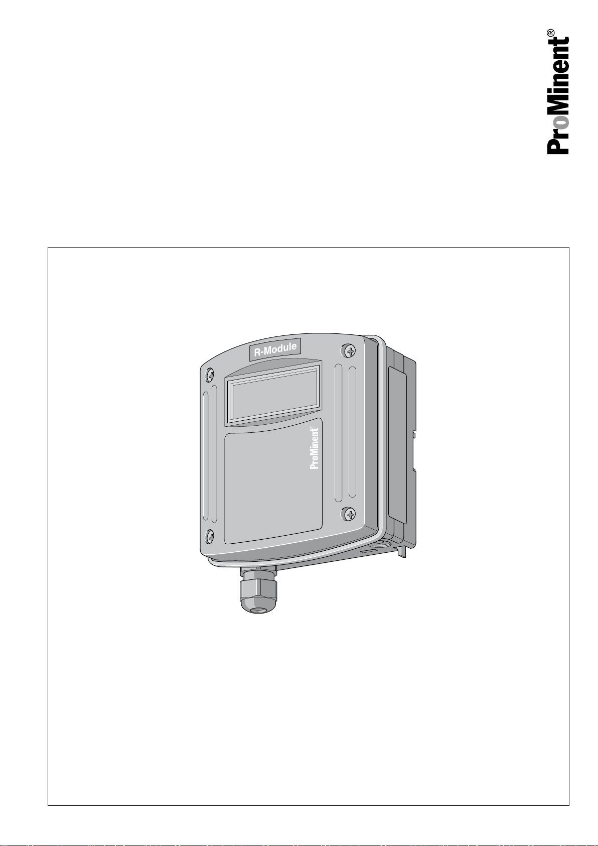
DULCOMARIN®, R Module
Control unit for chlorine gas metering device,
DXMaR
EN
These operating instructions are only valid in conjunction with the "Operating instructions for the DULCOMARIN®”.
Please carefully read these operating instructions before use. · Do not discard.
The operator shall be liable for any damage caused by installation or operating errors.
The latest version of the operating instructions are available on our homepage.
986539 Version: BA DC 090 03/19 EN
Page 2

Table of contents
Table of contents
1 Identity code.......................................................................... 3
2 Safety and responsibility....................................................... 4
3 Handling the device.............................................................. 5
4 Wiring diagram...................................................................... 6
2
Page 3

1 Identity code
Identity code
The identity code describes the external modules
for the DULCOMARIN®.
DXMa
External modules for the DULCOMARIN
Module:
M M module, measuring module: pH, ORP, temperature
A A module, control module: 3 pumps and 4 analogue outputs
R
N
P
R module, control module: Chlorine gas metering device with feedback
N module, power supply module without relay
P module, power supply module without relay, only mounting type
I I module, current input module, 3 mA inputs, 2 digital inputs
Mounting type:
0 Without housing, only P-module (IP 00)
W Wall mounted (IP 65)
H Mounting rail (IP 20)
E Upgrade module (insert module for DXCa, IP 20)
Design:
0 With controls
2 Without controls
®
1) 2)
1) 2)
2)
‘0’
3 Without controls (only mounting type
Application:
0 Standard
S Swimming pool (only M module)
Language:
00
No controls
EN German
EN English
ES Spanish
FR French
IT Italian
Certification:
00 No certification, only P module without housing
01 CE certification
1)
only mounting type W wall mounting / 2) only in version
‘E’
2)
‘2’
without operation
)
3
Page 4

Safety and responsibility
2 Safety and responsibility
NOTICE!
Further applicable documents
These operating instructions are only valid in con‐
junction with the "Operating instructions for DUL‐
COMARIN®”.
All the safety information and explanations con‐
tained therein must be observed without exception.
NOTICE!
Intended use
– You many only use the DXMaR R module to
control a servomotor.
– You many only use the DXMaR R module as
part of a DULCOMARIN®.
– Any other uses or modifications are prohibited.
WARNING!
Danger of malfunctions
Only trained personnel may install the DXMaR R
module. Only then can it be ensured that all com‐
ponents of the control circuit are matched to each
other and operating correctly.
4
Page 5

3 Handling the device
Storage and transport
Assembly and installation
Handling the device
CAUTION!
Protect the module against moisture and the
effects of chemicals, even while still packaged.
Store and transport the module it its original packaging.
Ambient conditions for storage and transport:
n Temperature: -10 °C ... 70 °C.
n Max. permissible relative humidity: 95%, non-condensing (DIN
IEC 60068-2-30).
WARNING!
Danger of malfunctions
Only trained personnel may install the DXMaR R
module. Only then can it be ensured that all com‐
ponents of the control circuit are matched to each
other and operating correctly.
Wiring diagram
The wiring diagram can be found at the end of these operating
instructions, see
Create the CAN connection in accordance with the operating
instructions for the DULCOMARIN®.
Ä Chapter 4 ‘Wiring diagram’ on page 6
.
5
Page 6

Leistungsrelais-Ausgänge
Stellungsrückmelde-Eingang
Intern
Extern
Speisespannung
schließen
öffnen
offen
geschlossen
A0449
Wiring diagram
4 Wiring diagram
WARNING!
Danger to life due to chlorine gas
Chlorine gas can escape if a chlorine gas metering
device is accidentally set to
‘OPEN’
.
Possible consequence: Fatal or very serious inju‐
ries.
Measure: Lock the power supply to the chlorine
gas metering device in the event of a failure of the
chlorine gas metering device, doing the same with
the power supply to the booster pump and the cir‐
culating pump to shut the booster pump and the
circulating pump down or take appropriate meas‐
ures to prevent the uncontrolled escape of chlorine
gas.
Fig. 1: Wiring diagram
6
Page 7

Wiring diagram
Tab. 1: Terminal assignment
Name Terminal identifier Terminal no. Pole Function
Output relay output1P1 1 C Shut the servomotor.
2 NO
3 NC
Output relay output2P2 4 C Open the servomotor.
5 NO
6 NC
Response signal
input
Electrical data
XR 7 - Feedback servomotor
8 S
position.
9 +
Output relay output (P1, P2):
n Type of contact: Changeover contact with interference-sup‐
pressed varistors
n Load capacity: 250 V AC, 3 A max., 700 VA
n Contact lifespan: > 20 x 105 switching operations
Position feedback input: XR
n Galvanically isolated from the power relay contacts
n Insulation voltage: 500 V
n Potentiometer to be connected: 0 Ω ... 1 kΩ
n Accuracy (without potentiometer errors): 1% of input range
n Dissolution: 0.5 % of input range
n Manipulating time: min.: 25 s / max.: 180 s
7
Page 8

ProMinent GmbH
Im Schuhmachergewann 5 - 11
69123 Heidelberg
Telephone: +49 6221 842-0
Fax: +49 6221 842-419
Email: info@prominent.com
Internet: www.prominent.com
986539, 2, en_GB
© 2019
 Loading...