

Page 1
Assembly and operating instructions
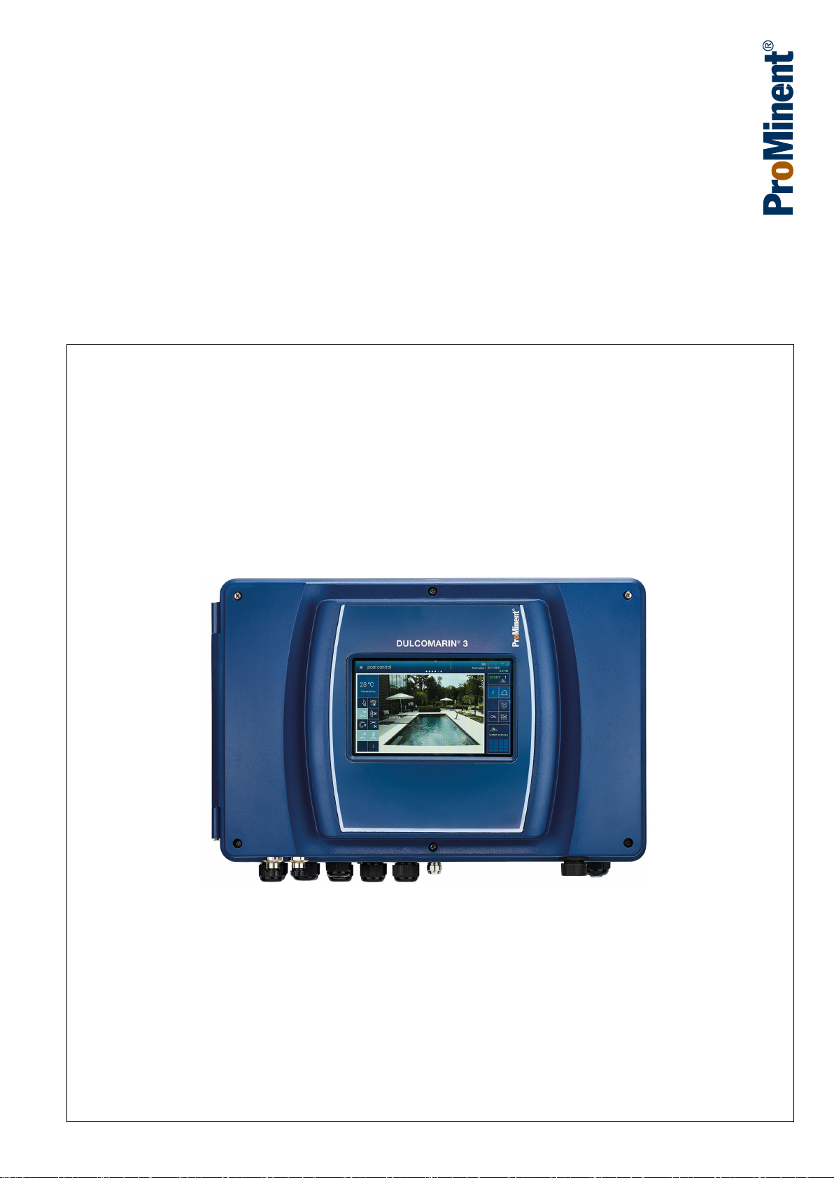
A2600
Multi-channel measuring and control system
DULCOMARIN® 3 Compact
EN
Please carefully read these operating instructions before use. · Do not discard.
The operator shall be liable for any damage caused by installation or operating errors.
The latest version of the operating instructions are available on our homepage.
Target group: Trained user.Part number: 982801 Version: BA DC 089 09/18 EN
Page 2

Supplemental directives
General non-discriminatory approach
Supplementary information
In order to make it easier to read, this document uses the male
form in grammatical structures but with an implied neutral sense. It
is aimed equally at both men and women. We kindly ask female
readers for their understanding in this simplification of the text.
Please read the supplementary information in its entirety.
Information
This provides important information relating to the
correct operation of the unit or is intended to make
your work easier.
Warning information
Warning information includes detailed descriptions of the haz‐
ardous situation, see
tion’ on page 6
Ä Chapter 1.2 ‘Labelling of Warning Informa‐
.
The following symbols are used to highlight instructions, links, lists,
results and other elements in this document:
Tab. 1: More symbols
Symbol Description
Action, step by step.
⇨ Outcome of an action.
Links to elements or sections of these instructions or other applicable documents.
n
[Button]
List without set order.
Display element (e.g. indicators).
Operating element (e.g. button, switch).
‘Display /GUI’
CODE
Screen elements (e.g. buttons, assignment of function keys).
Presentation of software elements and/or texts.
2
Page 3

Table of contents
Table of contents
1 Safety and responsibility....................................................... 6
1.1 Introduction................................................................... 6
1.2 Labelling of Warning Information.................................. 6
1.3 General safety information............................................ 7
1.4 Intended use................................................................. 9
1.5 User qualification........................................................ 10
1.6 Warranty..................................................................... 10
1.7 Network security......................................................... 11
2 Functional description......................................................... 12
2.1 Open-source software licences.................................. 13
3 Operating concept............................................................... 14
3.1 Operating elements.................................................... 14
3.2 Navigation levels......................................................... 17
3.2.1 Interactions.............................................................. 18
3.2.2 Navigation levels...................................................... 19
4 Access to the setting menus............................................... 26
4.1
Hamburger menu with access to the system......... 26
4.2
Hamburger menu with access to the selected
pool............................................................................. 27
4.3
Cog wheel icon ....................................................... 28
4.4 Swiping and tapping on the display............................ 29
5 Storage and transport......................................................... 30
6 Assembly and installation................................................... 31
6.1 Scope of delivery........................................................ 31
6.2 Installation, mechanical.............................................. 32
6.2.1 Wall mounting.......................................................... 32
6.3 Electrical installation................................................... 35
6.3.1 Dimensioning/ arrangement of threaded connec‐
tors........................................................................... 36
6.3.2 Connection labels, base module.............................. 37
6.3.3 Terminal layout........................................................ 46
6.3.4 Terminal diagram..................................................... 47
6.3.5 Cable Cross-Sections and Cable End Sleeves....... 55
6.3.6 Switching of inductive loads..................................... 55
6.3.7 Connect the sensors electrically to the controller.... 56
6.4 Compact system, arrangement of components, CAN
connectivity................................................................. 61
6.4.1 Principles................................................................. 61
6.4.2 T-connectors............................................................ 62
6.4.3 Terminal resistances................................................ 62
6.5 CAN construction........................................................ 63
6.5.1 Determine the requirement for cables and accesso‐
ries........................................................................... 65
6.5.2 Routing the CAN bus backbone.............................. 66
7 Interfaces............................................................................ 68
7.1 SD card....................................................................... 68
7.2 USB port..................................................................... 69
7.3 LAN interface.............................................................. 69
7.3.1 Digital certificate...................................................... 70
3
Page 4

Table of contents
7.4 Wi-Fi interface (optional)............................................. 70
8 Data logger......................................................................... 72
9 Operating the device........................................................... 73
9.1 Home.......................................................................... 73
9.2 System settings.......................................................... 73
9.2.1 Login/logout............................................................. 73
9.2.2 Setting the language................................................ 73
9.2.3 Display..................................................................... 73
9.2.4 System > System settings....................................... 74
9.2.5 Network.................................................................... 75
9.2.6 Web services > NETWORK settings....................... 76
9.2.7 User administration.................................................. 76
9.2.8 Screen recorder....................................................... 77
9.2.9 E-mail....................................................................... 77
9.2.10 Bar graphs............................................................. 77
9.2.11 Network CAN......................................................... 78
9.2.12 Wizards.................................................................. 78
9.2.13 Gateway (planned extension)................................ 78
9.2.14 Functional test....................................................... 78
9.2.15 Default settings...................................................... 78
9.3 Help topics.................................................................. 79
9.4 Information.................................................................. 79
9.5 Calibrating................................................................... 79
9.6 Screen recorder.......................................................... 79
9.7 Pool control (attractions)............................................. 79
9.8 Single pool > Measured values pool........................... 79
9.9 Measured values pool................................................. 80
9.10 Process flowchart..................................................... 80
9.11 Connectivity.............................................................. 80
9.12 Pool settings............................................................. 80
9.12.1 ECO mode parameters.......................................... 80
9.12.2 Timer details operating mode................................ 80
9.12.3 Background image, pool geometry, pool name..... 80
9.12.4 Superchlorination................................................... 81
10 Application-specific settings................................................ 82
11 Calibrating........................................................................... 84
11.1 Calibrate: measured variable, pH............................. 85
11.2 Calibrate: measured variable, ORP.......................... 87
11.3 Calibrate: measured variable, free chlorine.............. 88
11.4 Calibrate: measured variable, total available
chlorine..................................................................... 89
11.5 Calibrate: measured variable, total chlorine............. 89
11.6 Calibrate: measured variable, total available bro‐
mine.......................................................................... 90
11.7 Calibrate: measured variable, total bromine............. 90
11.8 Calibrate: measured variable, chlorine dioxide......... 91
11.9 Calibrate: measured variable, chlorite...................... 91
11.10 Calibrate: Temperature measured variable............ 92
12 Flocculant treatment........................................................... 93
4
Page 5

Table of contents
13 Factory settings of device................................................... 94
13.1 Factory settings for free chlorine measured vari‐
able........................................................................... 94
13.2 Factory settings for combined chlorine measured
variable..................................................................... 95
13.3 Factory settings for pH measured variable............... 96
13.4 Factory settings for ORP measured variable............ 97
13.5 Factory settings for temperature measured vari‐
able........................................................................... 98
14 Commissioning................................................................... 99
15 Diagnostics, error and warning messages........................ 101
16 Software update................................................................ 102
17 Maintenance..................................................................... 103
18 Technical data................................................................... 104
18.1 General information................................................ 104
18.2 Electrical data......................................................... 104
19 Spare parts and accessories............................................ 107
19.1 Spare parts............................................................. 107
19.2 Accessories............................................................ 107
20 Formal information and standards.................................... 109
20.1 Disposal of used parts............................................ 109
20.2 Standards complied with and Declaration of Con‐
formity..................................................................... 109
21 Index................................................................................. 110
5
Page 6
Safety and responsibility
1 Safety and responsibility
1.1 Introduction
Target group of document
General knowledge of measuring and control technology and
swimming pool technology is required in order to understand the
document. Furthermore, the planning and use of measuring and
control technology and swimming pool technology require technical
specialist knowledge, which is not communicated in this document.
The minimum requirement of personnel is “trained user”, see
Ä Chapter 1.5 ‘User qualification’ on page 10
specified.
Assembly and operating instructions
The printed version of the assembly and operating instructions is
naturally not updated. We would therefore ask you to regularly visit
the manufacturer’s homepage www.prominent.com to find out
about the new electronic versions of the assembly and operating
instructions. These versions may contain, among other things,
information about new fault remedies or spare parts.
1.2 Labelling of Warning Information
Introduction
These operating instructions provide information on the technical
data and functions of the product. These operating instructions pro‐
vide detailed warning information and are provided as clear stepby-step instructions.
The warning information and notes are categorised according to
the following scheme. A number of different symbols are used to
denote different situations. The symbols shown here serve only as
examples.
, unless otherwise
DANGER!
Nature and source of the danger
Consequence: Fatal or very serious injuries.
Measure to be taken to avoid this danger.
Description of hazard
– Denotes an immediate threatening danger. If
the situation is disregarded, it will result in fatal
or very serious injuries.
WARNING!
Nature and source of the danger
Possible consequence: Fatal or very serious inju‐
ries.
Measure to be taken to avoid this danger.
– Denotes a possibly hazardous situation. If the
situation is disregarded, it could result in fatal
or very serious injuries.
6
Page 7
Safety and responsibility
CAUTION!
Nature and source of the danger
Possible consequence: Slight or minor injuries.
Material damage.
Measure to be taken to avoid this danger.
– Denotes a possibly hazardous situation. If the
situation is disregarded, it could result in slight
or minor injuries. May also be used as a
warning about material damage.
NOTICE!
Nature and source of the danger
Damage to the product or its surroundings.
Measure to be taken to avoid this danger.
– Denotes a possibly damaging situation. If the
situation is disregarded, the product or an
object in its vicinity could be damaged.
1.3 General safety information
Type of information
Hints on use and additional information.
Source of the information. Additional measures.
–
Denotes hints on use and other useful informa‐
tion. It does not indicate a hazardous or dam‐
aging situation.
WARNING!
Live parts!
Possible consequence: Fatal or very serious inju‐
ries
– Measure: Before undertaking installation work
on the open device, ensure that it is discon‐
nected from the power supply.
– Regularly monitor the devices and de-energise
damaged or defective devices, or devices that
have been tampered with, from the power
supply.
– The operator must install a suitable circuit
breaker (e.g. IEC 60947-1 and IEC 60947-3)
for this.
– When switching off the device, the operator
must ensure that the entire process remains
safe.
– The operator should fit a residual current
device (RCD) or another suitable measure to
protect personnel and equipment.
7
Page 8

Safety and responsibility
WARNING!
Danger from hazardous substances!
Possible consequence: Fatal or very serious inju‐
ries.
Please ensure when handling hazardous sub‐
stances that you have read the latest safety data
sheets provided by the manufacture of the haz‐
ardous substance. The actions required are
described in the safety data sheet. Check the
safety data sheet regularly and replace, if neces‐
sary, as the hazard potential of a substance can be
re-evaluated at any time based on new findings.
The system operator is responsible for ensuring
that these safety data sheets are available and that
they are kept up to date, as well as for producing
an associated hazard assessment for the worksta‐
tions affected.
WARNING!
Unauthorised access!
Possible consequence: Fatal or very serious inju‐
ries.
– Measure: Ensure that there can be no unau‐
thorised access to the device.
WARNING!
Operating faults!
Possible consequence: Fatal or very serious inju‐
ries.
– Ensure that the device is only operated by ade‐
quately qualified and technically expert per‐
sonnel.
– Please also observe the operating instructions
for sensors and fittings and any other units
which may be fitted, such as sample water
pumps etc.
– The operator is responsible for ensuring that
personnel are qualified.
NOTICE!
Correct sensor operation
Damage to the product or its surroundings.
– Correct measurement and metering is only
possible if the sensor is working perfectly.
– Check and calibrate the sensor regularly.
8
Page 9

1.4 Intended use
Safety and responsibility
Protection of radio reception
This equipment is not intended to be used in resi‐
dential areas and cannot guarantee appropriate
protection of radio reception in these environ‐
ments.
The control’s limit values need to be permanently activated with
swimming pool controllers.
The unit is designed to measure and regulate water treatment in a
swimming pool with one or more pools.
The unit’s range of application extends to industry and residential.
Only use the unit in accordance with the technical details and
specifications provided in these operating instructions and in the
operating instructions for the individual components (such as sen‐
sors, fittings, calibration devices, metering pumps, etc.).
The controller can be used in processes, which have a time con‐
stant of > 30 seconds.
All other uses or modifications are prohibited.
Interference resistance
The device complies with the interference resistance provisions in
accordance with EN 61326-1 and is intended for use in industrial
electromagnetic environments and in residential areas.
WARNING!
Disturbance signal emissions class A or B / Protec‐
tion for radio reception
The device complies with the disturbance signal
emissions test requirements for residential areas
as a Class B (Residential area), Group 1 unit.
With devices with communication interface
– B = Profibus,
– E = LAN,
– G = Profinet,
the unit only complies with the limit values for a
class A device (other areas apart from residential),
Group 1.
This device is then not intended to be used in resi‐
dential areas and cannot guarantee appropriate
protection of radio reception in these environ‐
ments.
9
Page 10

Safety and responsibility
1.5 User qualification
WARNING!
Danger of injury with inadequately qualified per‐
sonnel
The operator of the system / equipment is respon‐
sible for ensuring that the qualifications are ful‐
filled.
If inadequately qualified personnel work on the unit
or loiter in the hazard zone of the unit, this could
result in dangers that could cause serious injuries
and material damage.
– All work on the unit should therefore only be
conducted by qualified personnel.
– Unqualified personnel should be kept away
from the hazard zone.
The pertinent accident prevention regulations, as
well as all other generally acknowledged safety
regulations, must be adhered to.
Training Definition
Instructed personnel An instructed person is deemed to be a person who has been instructed and,
if required, trained in the tasks assigned to him and possible dangers that
could result from improper behaviour, as well as having been instructed in the
required protective equipment and protective measures.
Trained user A trained user is a person who fulfils the requirements made of an instructed
person and who has also received additional training specific to the system
from the manufacturer or another authorised distribution partner.
Trained, qualified per‐
sonnel
Electrical technician An electrical technician is able to complete work on electrical systems and rec‐
A trained, qualified employee is deemed to be a person who is able to assess
the tasks assigned to him and recognize possible hazards based on his
training, knowledge and experience, as well as knowledge of pertinent regula‐
tions. A trained, qualified employee must be able to perform the tasks
assigned to him independently with the assistance of drawing documentation
and parts lists. The assessment of a person's technical training can also be
based on several years of work in the relevant field.
ognise and avoid possible dangers independently based on his technical
training and experience as well as knowledge of pertinent standards and regu‐
lations. An electrical technician must be able to perform the tasks assigned to
him independently with the assistance of drawing documentation, parts lists,
terminal and circuit diagrams. The electrical technician must be specifically
trained for the working environment in which the electrical technician is
employed and be conversant with the relevant standards and regulations.
Service The Service department refers to service technicians, who have received
proven training and have been authorised by the manufacturer to work on the
system.
1.6 Warranty
The general terms and conditions of business, contracts and
national laws and regulations apply in the relevant order of priority.
10
Page 11

1.7 Network security
Safety and responsibility
The product is suitable for use in networks. Users are responsible
for taking appropriate security measures for their own network and
all components contained therein, in particular their computer sys‐
tems and other systems. They must protect these adequately from
unauthorised access by third parties, viruses, harmful software and
any other forms of harmful elements. In particular, the user under‐
takes to set up an appropriate firewall and wherever possible to
use automatically generated passwords of an adequate length,
which should be regularly changed, or to take other appropriate
measures to establish or maintain network security. Responsibility
for network security lies with the operator of the system.
ProMinent GmbH in particular is not liable for any consequences
resulting from inadequate security measures and the potential
misuse of the user’s identification features.
11
Page 12

Functional description
2 Functional description
The measuring and control system DULCOMARIN® 3 controls the
entire range of swimming pools – from private pools to public
adventure pools.
The measuring and control system DULCOMARIN® 3 is used to
treat swimming pool water. Eco!Mode® adapts the circulation
capacity for on-demand energy use.
The system is operated either via the 7” touchscreen with graphic
user interface or using mobile smart devices by means of the inte‐
grated web server while maintaining full functionality. Explanatory
videos guide the user step-by-step through operation.
By using industrial bus systems, up to 16 pool circuits can be net‐
worked and the amount of wiring needed is reduced at the same
time. Local operating devices can be added to each pool circuit.
This simplifies regular maintenance of the swimming pool system
(e.g. sensor calibration). The modular construction allows existing
systems to be extended.
Field of application
Overview of the functions
n Water parks,
n public swimming pools,
n private pools.
Measurement and control of all relevant hygiene parameters.
n pH,
n ORP,
n chlorine, total / combined / free,
n bromine,
n chlorine dioxide,
n temperature,
n conductivity,
n turbidity.
Control of the swimming pool technology:
n circulating pumps, on-demand thanks to Eco!Mode®,
n filter backflushing,
n lighting,
n covers,
n whirlpool functions,
n attractions such as counterflow systems.
Evaluation and reporting functions:
n high-resolution screen recorders with zoom function,
n comprehensive data logger for evaluations on a PC,
n sending configurable status messages by e-mail.
Communication options:
n linking to building management systems by means of KNX /
OPC standard,
n PLC linking by means of PROFIBUS® DP and Modbus RTU,
n LAN and Wi-Fi connections for operation using a PC, tablet or
smartphone etc.
12
Page 13

2.1 Open-source software licences
The DULCOMARIN® 3 controller may contain firmware with opensource software packages. You will find a list in table format of the
possible software packages, the licensing conditions for these
packages and the source code on the data carrier provided with
the controller and on the product and download page for the DUL‐
COMARIN® 3.
Functional description
13
Page 14
System overview
System designation
System 1... 3
Pool overview
2018-06-22
14:21:28
Pool name 1
1
ECO
2
ECO
Pool name 3
3
CAL
Input screen locked!
Swipe to unlock.
A2495
Operating concept
3 Operating concept
3.1 Operating elements
Operating elements
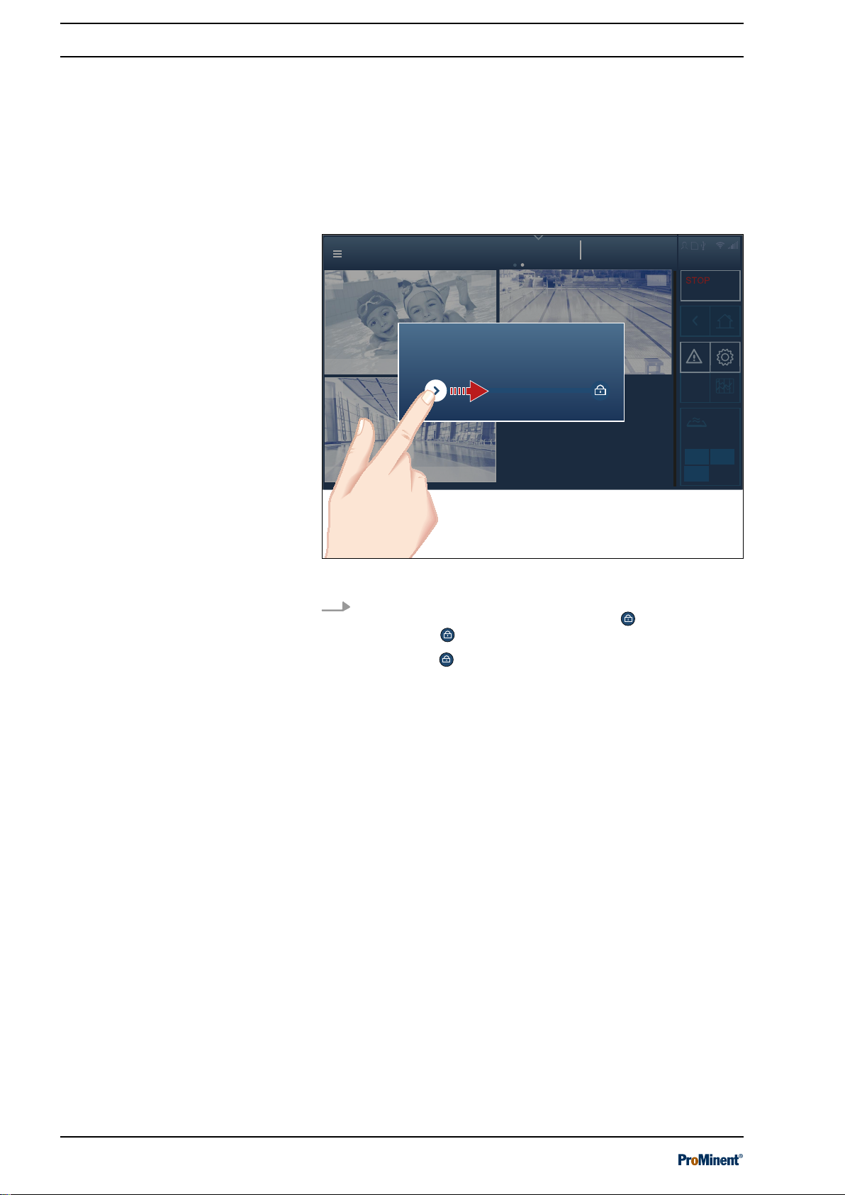
The device is operated by a touchscreen as a combined input and
output interface between man and machine (HMI).
The capacitative touchscreen display provides a quick overview of
all functions. It responds like a smartphone, which ensures simple
and intuitive operation.
Fig. 1: Locked screen
To unlock: use the tip of your finger to move the left icon and
drag the icon to the right towards the lock . Cover the lock
with the icon .
The lock
ð
opens.
14
Page 15

Operating elements
Help topics
System overview
2018-11-06
14:21:28
CAL
Pool name
System 1... 3
STOPSTOP
Pool measured value
Pool name
Off
System overview
pH
Target
0.00
pH
Dosing
ON
Dosing
-100.0 %
ON
Target 0
ORP
mV
Dosing
Target 0.0
Temperature
Dosing
Target 0.00
Free chlorine
ppm
Dosing
Target 0.00
Total chlorine
m3/h
Dosing
Cl combined
Target 0.00
OFF
START 1
System information
Start/Stop
Pool
Home
Start screen
Settings
Recorder
System overview
Status display of
pools and link to
start screen
back
Alarms
Errors & warnings
Calibrate
active pool
Page index
Menu
Pool name 1
OFF
START
1
06/11/2017
System overview
CAL
active pool
14:21:28
A2519
ON
Operating concept
Fig. 2: The individual operating elements
Reciprocal
n
‘ON’
n
‘OFF’
‘ON/ OFF’
status ➨
status ➨
to
‘START/STOP’
‘STOP’
pool display (at pool level)
‘START’
pool display (at pool level)
If the status display for a pool is indicating the
[STOP]
key can be used to stop the control and outputs of this
pool.
If the status display for a pool is indicating the
the
[START]
key can be used to start the control and outputs of
this pool.
All pools can be stopped at system level using the
[system 1 ... n]
. Each pool can then only be started individually.
status
[ON]
status, then the
[OFF]
status, then
[STOP]
key
15
Page 16
Becken 1...3
2018-06-22
14:21:28
Operating concept
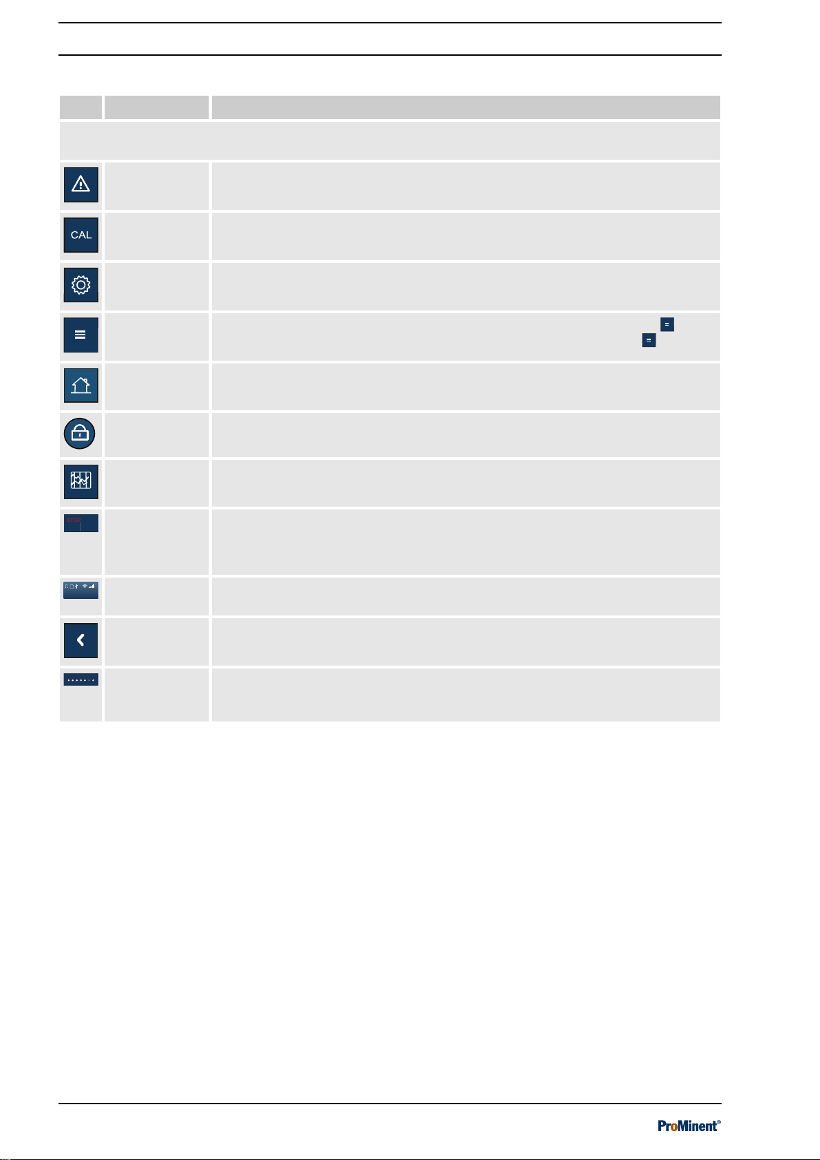
Tab. 2: Pictograms as operating elements.
Picto. Name Meaning and function
Active pictograms are highlighted, while inactive pictograms remain dimmed. Only the active pictograms
can be actuated.
System alarms This key immediately opens the global list with all system alarms.
Calibration
This key immediately opens the calibration menu.
menu
System set‐
This key immediately opens the list with all system settings.
tings
Quick access
menu
[Home]
This key immediately opens the quick access menu (
can then select from the various sub-menus in the
This key takes you straight back to the screen defined as
Locked lock This icon indicates that the display is locked.
Screen
recorder
Pool status Reciprocal
General infor‐
mation
This key immediately opens the view with the recorder. The screen recorder logs
all the device’s activities and measured values.
‘ON/ OFF’
n
‘ON’
status➨
n
‘OFF’
status ➨
to
‘STOP’
‘START’
‘START/STOP’
display
display
status
You will find all information about the date, time and links between the various
interfaces displayed here.
‘hamburger’
‘hamburger’
[Home]
menu) . You
menu .
.
Back This key takes you one level back in the menu.
Page index These points at the top of the display indicate that there are more pages. You can
access these pages by swiping to the left or right. The dark point marks the posi‐
tion of the visible page in the entire system.
16
Page 17

3.2 Navigation levels
Login
System designation
2018-06-22
14:21:28
Select user
A2532
Login
System designation
2018-06-22
14:21:28
Select user
Name User2
User
alias User1
Service
A2533
Login
Select user
Operating concept
Fig. 3: Login interface
Fig. 4: User selection interface
17
Page 18
Login
System designation
2018-06-22
14:21:28
alias User1
Service
1 2 3
4 5 6
987
0
A2534
Help topics
System overview
2018-06-22
14:21:28
System designation
System 1... 3
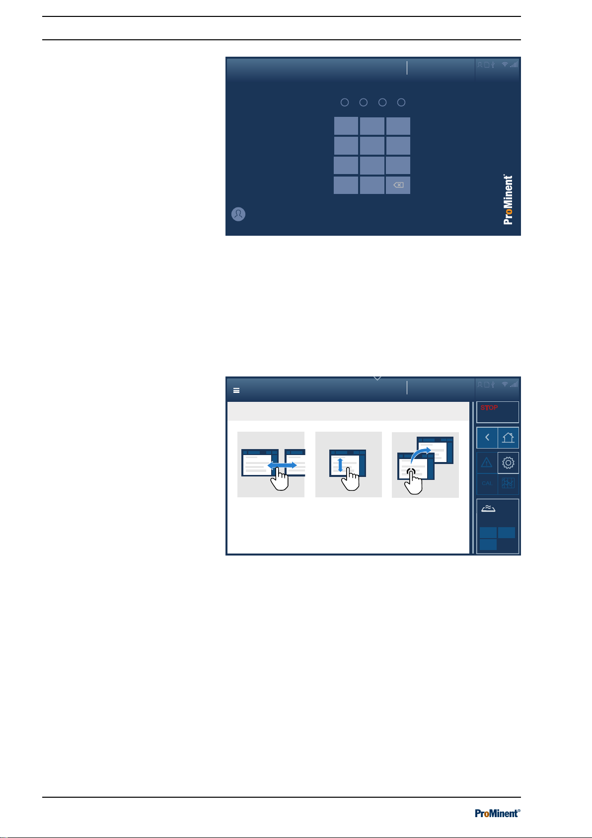
Navigation principle, interaction
Swipe
Navigate to
next screen on the same
level.
Scroll
Display further content on the
same screen
.
Tap
Navigate to
following screen on
the next level.
A2518
Operating concept
Entering a PIN/PUK
Fig. 5: PIN entry interface
You can enter the PIN you have assigned here. If you can’t
remember your PIN, you can enter the PUK. The PUK is supplied
with the device and can be found in a sealed envelope. It is the
responsibility of the operator to ensure that the PUK is kept safe
and is available when needed.
3.2.1 Interactions
Fig. 6: Swiping, scrolling and tapping
18
Page 19

3.2.2 Navigation levels
Help topics
System overview
2018-06-22
14:21:28
CAL
System designation
System 1... 3
STOPSTOP
System level
Pool level
Detail level
Navigation levels (principle)
1.1
1.3
1.2
2.1
2 x
2.2
2 y
3.1
3 x
3.2
3 y
A2517
System overview
System designation
System 1... 3
System overview
2018-06-22
14:21:28
1
ECO
ECO
2
ECO
Rehabilitation
Children's pool
3
Competition pool
A2494
Operating concept
Fig. 7: Principle of navigation levels
Swipe between the pages of a level e.g. 1.1-1.3.
Tapping on a level takes you one level lower in the menu if this is
possible.
3.2.2.1 System level
System overview
Press to go back one level.
The Home key returns you to the
[Home]
screen.
Fig. 8: [Home] screen, here with the individual system overview.
You can set the layout and assignment in the
menu. Tapping on the
[Home]
You now have two options:
n Swipe over the display to move to the next display, or
n tap on the respective pool to view the measured value display.
screen.
[Home]
icon always takes you to the
[System settings]
19
Page 20
System measured values
System designation
System 1... 3
System overview
1.0 %
729
1.0 %
30.8
0.0 %
0.96
8.0 %
0.0 % 0.0 % 0.0 %0.0 %
0.0 % 0.0 % 0.0 %0.0 %
0.00
0.00
0.0
0.0
0
0
pH ORP Temp
Free chlorine
2018-06-22
14:21:28
STOP
A2504
Measured values pool
System 1
OFF
System overview
pH
Target
pH
Dosing
ON
Dosing
ON
Target 750
ORP
mV
Dosing
Target 30.0
Temperature
°C
Dosing
Target 1.15
Free chlorine
ppm
Dosing
Target 1.20
Total chlorine
ppm
Dosing
Combined chlorine
ppm
OFF
START 1
A2505
OFFOFF
Target 0.05
Operating concept
System measured values
Fig. 9: Measured values interface.
You can view all the system’s measured values for pools 1 to n.
Scrolling up or down over the display allows you to display all
pools.
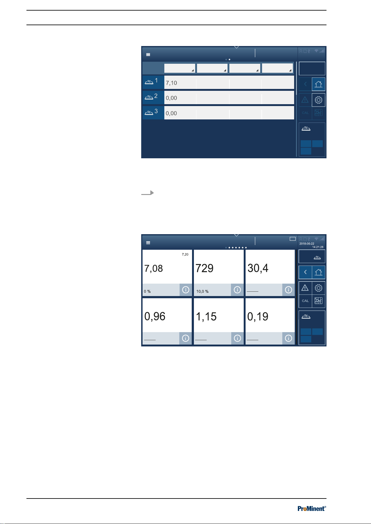
3.2.2.2 Pool level
Measured values of pools
Fig. 10: Measured values interface for the selected pool.
Up to 12 measured values = tiles can be displayed. The 7 points in
the centre at the top indicate that it is possible to swipe on this dis‐
play.
20
Page 21

Measured values pool
System overview
2018-06-22
14:21:28
pH
pH
Setpoint
pH
7.09
7.00 7.20 10.0%
On
Dosing
6.00
0.00
9.00
729
1.0 %
Dosing
On
ORP
mV
Setpoint
mV
730
600
900
0
Setpoint
°C
°C
30.5
Temperature
30.0
OFF
System 1
START 1
A2507
Measured values of pools, details
Operating concept
Fig. 11: Detailed pool display interface.
This display is more detailed, the set limit values are also displayed
here. The measured value, setpoint and metering are displayed at
a glance. The scroll bar indicates that there are more measured
values below – you therefore need to scroll upwards.
21
Page 22
Recorder
System overview
2018-06-22
14:21:28
pH ORP
Temperature
Free chlorine
System 1
OFF
START 1
A2508
Value ValueValueValue
Recorder details
System overview
2018-06-22
14:21:28
7.19 pH Value
499 mV
Value
28.7 °C Value Value
1.98 ppm
Dosing 01.0 %Dosing 00.0 %
Dosing 12.0 %Dosing 02.0 %
15 minutes
22.06.2018
System 1
OFF
START 1
A2509
Free chlorine
Temperature
ORPpH
1.
Operating concept
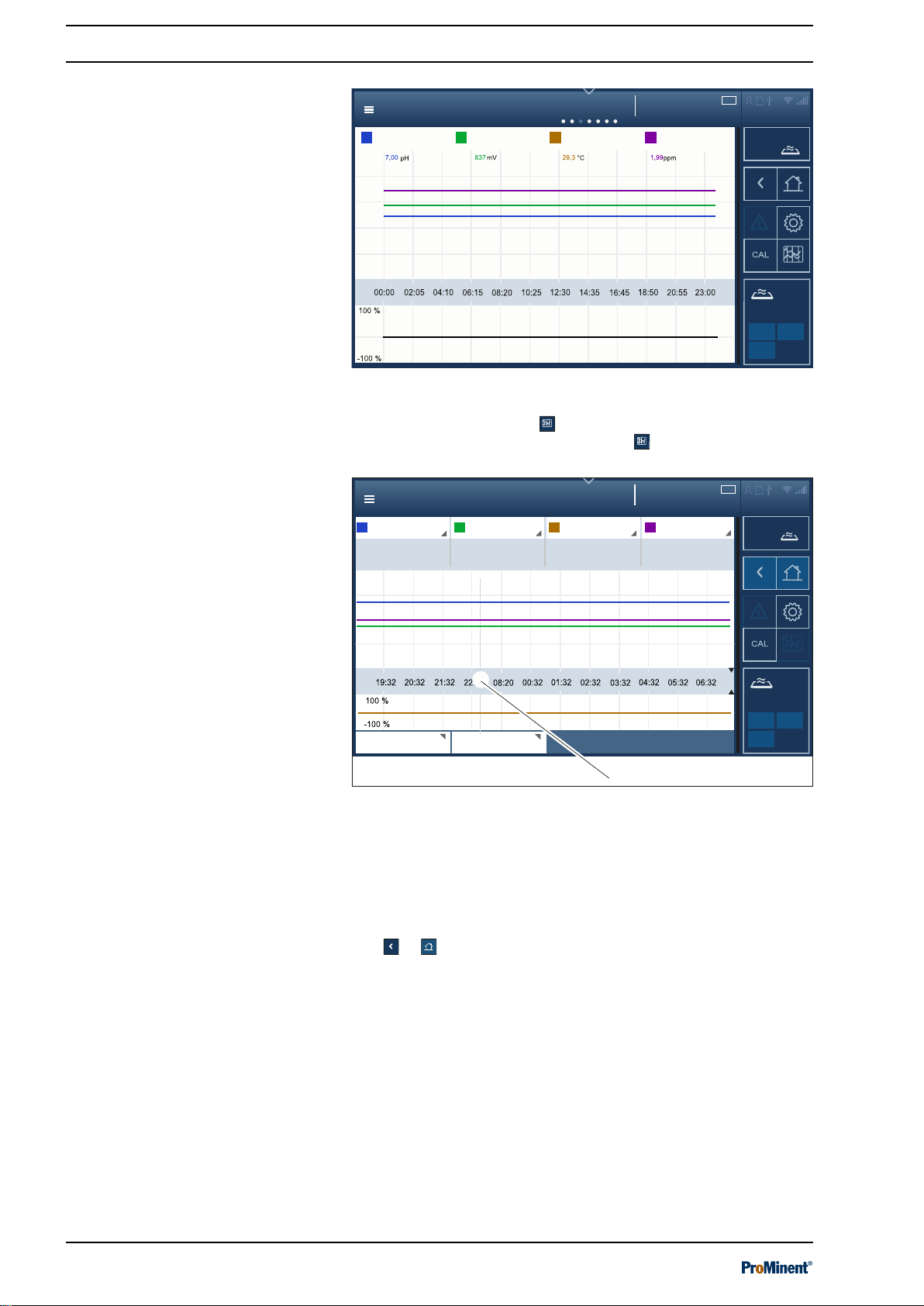
Screen recorder
Fig. 12: Screen recorder mode interface.
This is the screen recorder : tapping on it takes you to the next
page of the display. The screen recorder
logs all the device’s
activities and measured values.
Connectivity
Fig. 13: Interface of screen recorder with cursor (1.).
1 Cursor
The measured values at certain times can be displayed in this
screen recorder view by moving the cursor (1). By tapping on and
scrolling up/down the displays for measured variables, time and
date, you can also select other values or units, deactivate indi‐
vidual measured variables and adapt the time interval displayed.
Use or to go back.
Here you can monitor and configure the recognised CAN bus mod‐
ules and call up and read all the parameters required.
22
Page 23
Pool control
System 1
OFF
System overview
2018-06-22
14:21:28
START 1
Water temperature
30.6 °C
A2511
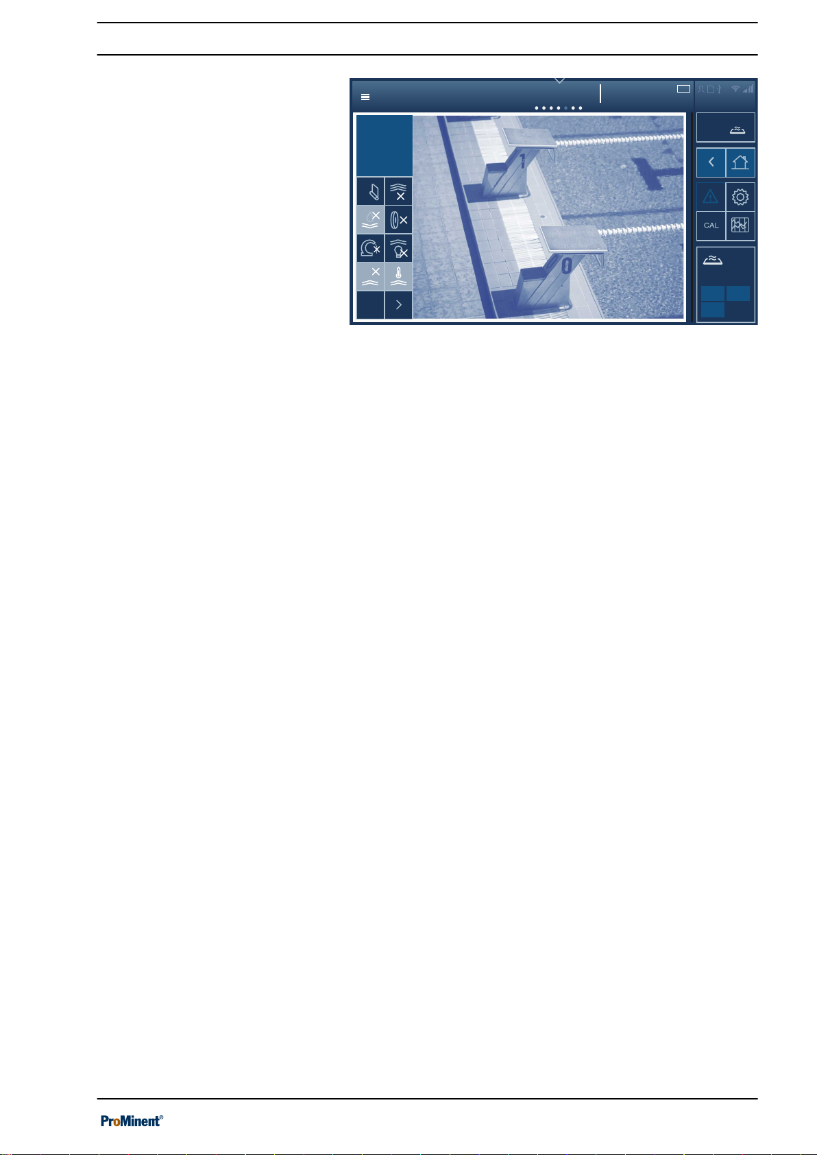
Pool control (attractions)
Operating concept
Fig. 14: Pool control interface (attractions)
You can switch the attractions (flood shower, fountains etc.) on and
off here.
23
Page 24
Process flowchart
System1
OFF
System overview
2018-06-22
14:21:28
START 1
Pump
Mode
Filter backflushing
Duration 0
Circulating pump
Normal mode...
50.0 m3/h
pH
ORP
Temp
Cl
Cl
comb.
7.10 pH
729
mV
30.5 °C
0.96 ppm
1.15 ppm
pH-
25.7 %
pH+
0 %
Cl
42.2 %
Floccculant
5.5 %
Auto
manual
1
A2512
Process flowchart
System 1
OFF
System overview
2018-06-22
14:21:28
CAL
START 1
Pump
Mode
Filter backflushing
Duration 0 s
Circulating pump
Normal mode...
50.0 m3/h
Cl
comb.
1.15 ppm
pH-
25.7 %
pH+
0 %
Cl
42.2 %
Floccculant
5.5 %
Auto
manual
Hydraulic details
Timer, circulating pump, level
A2513
Operating concept
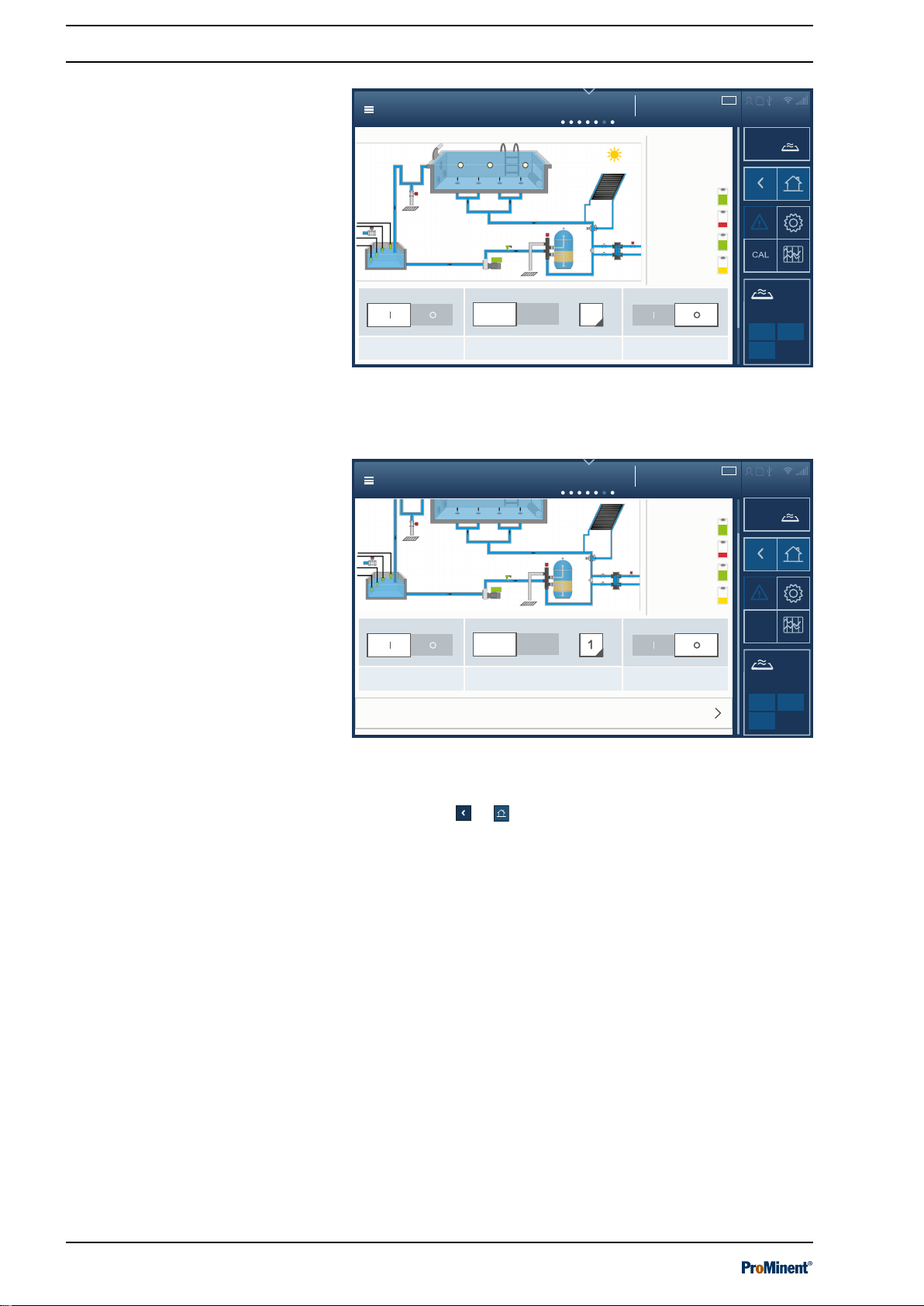
Process flowchart
Fig. 15: Process flowchart interface
Here you can switch the circulating pump off and on by tapping on
the circulating pump, for instance.
Fig. 16: Process flowchart interface showing the hydraulic details.
Scrolling up takes you to the hydraulic details, timer, circulating
pump etc. Use
or to go back.
24
Page 25
Pool settings
System 1
OFF
System overview
2018-06-22
14:21:28
START 1
Settings
Settings
Settings
ECO! mode parameters
A2514
Settings
Control parameters for superchlorination
Timer, details, operating mode
Background image, select pool geometry,
pool name
6.00
Details of measured variables
System overview
2018-06-22
14:21:28
Screen recorder of the last 2 hours
14.00
0.00
7.00
7.10
7.2
14.00
6.8
min
Alarms
max.
7.8
Setpoints and control parameters
Setpoint, normal mode
Setpoint, Eco!Mode
Superchlorination
7.27.2 7.1
OFF
System designation
START 1
A2506
pH
pH
1.
2.
3.
4.
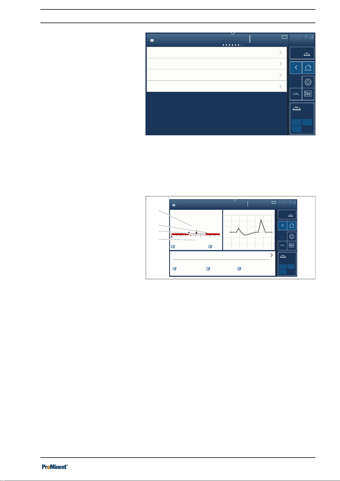
Pool settings
Operating concept
Fig. 17: Pool settings interface
You can set or select the parameters for Eco!Mode®, timer details,
operating modes, superchlorination and background images here.
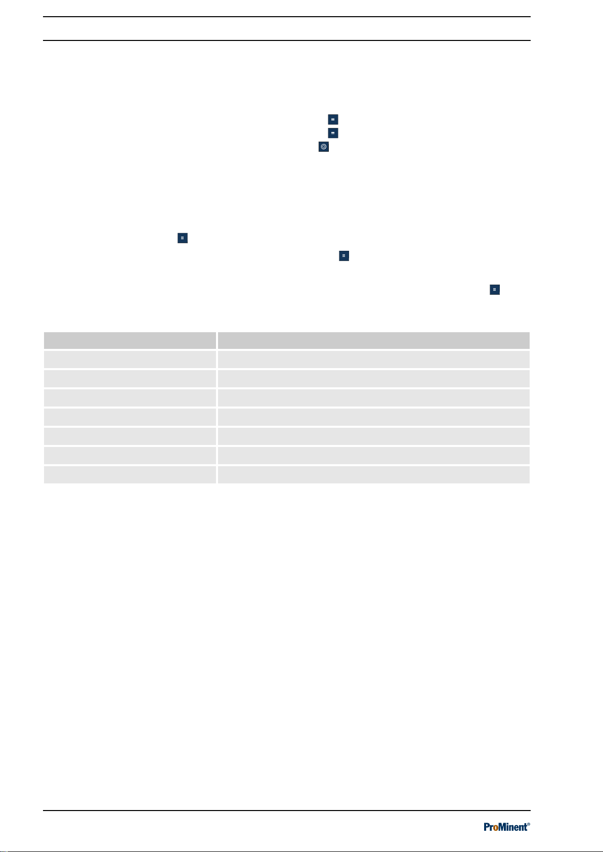
3.2.2.3 Detail level
Measured variables, details
Fig. 18: Details of measured variables interface.
Tapping on the desired measured value of the measured variable
takes you to the details of measured variables, the measured value
screen recorder for the last 2 hours, the control parameters and
setpoints for the operating modes: Normal, Eco!Mode® and super‐
chlorination. Here you can select the normal, Eco!Mode® and
superchlorination operating modes in order to set the parameters
for them.
25
Page 26
Access to the setting menus
4 Access to the setting menus
You can use various means of access to access the controller’s
setting menus:
n Hamburger menu with access to the system.
n Hamburger menu with access to the selected pool.
n Cog wheel icon .
n Swiping and tapping on the display.
For details of how to use all menus and interfaces, please consult
chapter
4.1 Hamburger menu with access to the system
In the Hamburger menu with access to the system, you can
undertake all settings, which affect the entire system and not cer‐
tain pools. More menu items only become visible once you select a
pool on the display, see
access to the selected pool’ on page 27
Ä Chapter 3 ‘Operating concept’ on page 14
.
Ä Chapter 4.2 ‘Hamburger menu with
.
Menu item Destination of the menu item
Login
Language settings
Safely remove the storage medium
System settings
Help topics
Info
Login.
Ä Chapter 9.2.1 ‘Login/logout’ on page 73
Ä Chapter 9.2.2 ‘Setting the language’ on page 73
Ä Chapter 9.2.8 ‘Screen recorder’ on page 77
Ä Chapter 9.2 ‘System settings’ on page 73
Ä Chapter 9.3 ‘Help topics’ on page 79
Ä Chapter 9.4 ‘Information’ on page 79
Ä Chapter 9.2.1 ‘Login/logout’ on page 73
26
Page 27

4.2 Hamburger menu with access to the selected pool
In the Hamburger menu with access to the selected pool, you
can undertake all settings, which affect a certain pool. The pool in
question is selected by tapping on the pool required before acti‐
vating the Hamburger menu .
Menu item Destination of the menu item
Access to the setting menus
Login
Language settings
Safely remove the storage
medium
System settings
Help topics
Info
Calibration
Screen recorder
Pool control
Single pool
Measured values pool
Process flowchart
Connectivity
Home
Login
Ä Chapter 9.2.1 ‘Login/logout’ on page 73
Ä Chapter 9.2.2 ‘Setting the language’ on page 73
Ä Chapter 9.2.8 ‘Screen recorder’ on page 77
Ä Chapter 9.2 ‘System settings’ on page 73
Ä Chapter 9.3 ‘Help topics’ on page 79
Ä Chapter 9.4 ‘Information’ on page 79
Ä Chapter 11 ‘Calibrating’ on page 84
Ä Chapter 9.6 ‘Screen recorder’ on page 79
Ä Chapter 9.7 ‘Pool control (attractions)’ on page 79
Ä Chapter 9.8 ‘Single pool > Measured values pool’ on page 79
Ä Chapter 9.9 ‘Measured values pool’ on page 80
Ä Chapter 9.10 ‘Process flowchart’ on page 80
Ä Chapter 9.11 ‘Connectivity’ on page 80
Ä Chapter 9.1 ‘Home’ on page 73
Ä Chapter 9.2.1 ‘Login/logout’ on page 73
27
Page 28

Access to the setting menus
4.3 Cog wheel icon
The cog wheel icon takes you to the
Ä Chapter 9.2 ‘System settings’ on page 73
‘System settings’
Menu item Submenu item for which param‐
eters are to be set
Login free
Language Set the operating language
Display Display
Colour scheme
Screen lock
Maintenance interval
Date
Time
System Unit settings
Software update
‘System settings’
menu item. The
menu item contains the following submenus:
Destination of the menu item
Ä Chapter 9.2.1 ‘Login/logout’ on page 73
Ä Chapter 9.2.2 ‘Setting the language’ on page 73
Ä Chapter 9.2.3 ‘Display’ on page 73
Ä Chapter 9.2.3.4 ‘Colour scheme’ on page 74
Ä Chapter 9.2.3.5 ‘Screen lock’ on page 74
Ä Chapter 9.2.3.8 ‘Activating maintenance timer’
on page 74
Ä Chapter 9.2.3.1 ‘Date and time’ on page 73
Ä Chapter 9.2.3.2 ‘Setting units’ on page 74
Ä Chapter 9.2.4.1 ‘Unit settings’ on page 75
Ä Chapter 16 ‘Software update’ on page 102
Device restart
Network LAN
Wi-Fi
IP
DHCP client
DHCP server
Web services Intranet
Web server
FTP server
VNC server
User administra‐
tion
Recorder Recorder, settings
E-mail E-mail alarms, settings
Add/delete user
Change password
Ä Chapter 9.2.4 ‘System > System settings’
on page 74
Ä Chapter 7.3 ‘LAN interface’ on page 69
Ä Chapter 7.4 ‘Wi-Fi interface (optional)’
on page 70
Ä ‘DHCP client or DHCP server’ on page 75
Ä ‘DHCP client or DHCP server’ on page 75
Ä ‘DHCP client or DHCP server’ on page 75
Ä Chapter 9.2.6.1 ‘Web server settings’ on page 76
Ä Chapter 9.2.6.3 ‘Intranet’ on page 76
Ä Chapter 9.2.6 ‘Web services > NETWORK set‐
tings’ on page 76
Ä Chapter 9.2.6.2 ‘VNC server’ on page 76
Ä Chapter 9.2.7 ‘User administration’ on page 76
Ä Chapter 9.2.7 ‘User administration’ on page 76
Ä Chapter 9.2.8 ‘Screen recorder’ on page 77
Ä Chapter 9.2.9 ‘E-mail’ on page 77
Bar graphs Settings
Network CAN BUS details
Wizards Design wizard
Commissioning wizard
Calibration wizard
Ä Chapter 9.2.10 ‘Bar graphs’ on page 77
Ä Chapter 9.2.11 ‘Network CAN’ on page 78
Ä Chapter 9.2.12.1 ‘Design wizard’ on page 78
Ä Chapter 9.2.12.2 ‘Commissioning wizard’
on page 78
Ä Chapter 9.2.12.3 ‘Calibration wizard’ on page 78
28
Page 29

Access to the setting menus
Menu item Submenu item for which param‐
eters are to be set
Gateway KNX
OPC
IOT
Functional test Log books, network configura‐
tion
Default settings Complete system
User settings
Control parameter
4.4 Swiping and tapping on the display
Once you have selected a pool, you can select the following menu
items by swiping and tapping on the display.
Destination of the menu item
Ä Chapter 9.2.13 ‘Gateway (planned extension)’
on page 78
Ä Chapter 9.2.13 ‘Gateway (planned extension)’
on page 78
Ä Chapter 9.2.13.3 ‘IOT’ on page 78
Ä Chapter 9.2.14 ‘Functional test’ on page 78
Ä Chapter 9.2.15 ‘Default settings’ on page 78
Menu item Destination of the menu item
Measured values pool
Recorder
Connectivity
Pool control
Process flowchart
Pool settings
Ä Chapter 9.9 ‘Measured values pool’ on page 80
Ä Chapter 9.6 ‘Screen recorder’ on page 79
Ä Chapter 9.11 ‘Connectivity’ on page 80
Ä Chapter 9.7 ‘Pool control (attractions)’ on page 79
Ä Chapter 9.10 ‘Process flowchart’ on page 80
Ä Chapter 9.12.1 ‘ECO mode parameters’ on page 80
Ä Chapter 9.12.2 ‘Timer details operating mode’ on page 80
Ä Chapter 9.12.3 ‘Background image, pool geometry, pool name’
on page 80
Ä Chapter 9.12.4 ‘Superchlorination’ on page 81
29
Page 30

Storage and transport
5 Storage and transport
n User qualifications, storage and transport: trained personnel
Ä Chapter 1.5 ‘User qualification’ on page 10
CAUTION!
Danger of material damage
The device can be damaged by incorrect or
improper storage or transportation!
– The unit should only be stored or transported in
a well packaged state - preferably in its original
packaging.
– The packaged unit should also only be stored
or transported in accordance with the stipu‐
lated storage conditions.
– The packaged unit should be protected from
moisture and the ingress of chemicals.
Packaging material
If required, dispose of the packaging material in an
environmentally responsible way. All packaging
components carry the corresponding recycling
code .
Ambient conditions for storage and
transport
Storage period
Transport weight
Store and transport the system in its original packaging.
Also protect the packaged systems against damp, exposure to
chemicals and mechanical effects.
Storage temperature: - 20 ... 70 °C.
Air humidity: < 95% relative humidity, non-condensing.
Humidity: None. Avoid rain and condensation.
Other: No dust, no direct sunlight.
There is no limit to the storage period.
The transport weight depends on the device’s equipment and lies
between 4 ... 8 kg.
30
Page 31

6 Assembly and installation
n User qualification, mechanical installation: trained and qualified
personnel
n User qualification, electrical installation: electrical technician
Ä Chapter 1.5 ‘User qualification’ on page 10
Assembly and installation
Ä Chapter 1.5 ‘User qualification’ on page 10
NOTICE!
Installation site and ambient conditions
– The controller meets the requirements for IP 67
(housing, closed) or IP 20 (housing, open) and
leak-tightness (based on NEMA 4X). These
standards are only met if all seals and
threaded connectors are correctly fitted.
– Only carry out the (electrical) installation after
(mechanical) installation.
– Ensure that there is unimpeded access for
operation.
– Ensure safe and low-vibration fixing.
– No direct sunlight.
– Permissible ambient temperature of the con‐
troller at the installation location: - 5 ... 50 °C at
max. 95% relative air humidity (non-con‐
densing).
– Requires a low voltage cable with a tempera‐
ture resistance of ≧ 70 °C.
– Take into consideration the permissible
ambient temperature of the connected sensors
and other components.
– The controller is only suitable for operation in
closed rooms. If operating outdoors, use a suit‐
able protective enclosure to protect the con‐
troller from the environment.
Mounting position
–
As standard, a wall-mounted controller is used.
–
Always install the controller so that the cable
entries point downwards.
–
Leave sufficient free space for the cables.
6.1 Scope of delivery
Tab. 3: The following components are included as standard:
Description Quantity
Measuring/control system DULCOMARIN® 3 including wall bracket.
Assembly material, complete, 2P universal (set). 2
Threaded cable connector set, M20 DCPa. 1
Data DVD. 1
Operating instructions. 1
Access card with PUK. 1
1
31
Page 32

424
415
137
127
76
276
276
A2566
40317570
Assembly and installation
6.2 Installation, mechanical
n User qualification, mechanical installation: trained and qualified
personnel
Ä Chapter 1.5 ‘User qualification’ on page 10
Fig. 19: Dimensional drawing, all dimensions in millimetres.
Install the device so that it is at eye level and is easily accessible to
operating personnel. Leave enough free space on the left of the
device for it to be folded open.
6.2.1 Wall mounting
Mounting materials (contained in the scope of delivery)
n 1 x wall bracket
n 4 x PT screws 5 x 35 mm
n 4 x washers 5.3
n 4 x rawl plug Ø 8 mm, plastic
32
Page 33

A0490
Wall mounting
Assembly and installation
Take the wall bracket out of the housing
Fig. 20: Removing the wall bracket
1. Pull the two snap hooks (1) outwards
The wall brackets snaps slightly downwards.
ð
2. Push the wall bracket downwards (2) from the housing and
fold (3) it out
3. Use the wall bracket as a drilling template to mark the posi‐
tions of four drill holes
4. Drill the holes: Ø 8 mm, d = 50 mm
33
Page 34

A0491
A0492
1
2
3
Assembly and installation
Fig. 21: Fitting the wall bracket
5. Screw the wall bracket into position using the washers, see
Fig. 21
Fig. 22: Fitting the wall bracket
6. Hook the bottom of the housing (1) into the wall bracket
7. Lightly press the housing at the top (2) against the wall
bracket
8. Then check that the housing is hooked in at the top and
press down (3) until it audibly engages
34
Page 35

6.3 Electrical installation
Assembly and installation
n User qualification, electrical installation: electrical technician
Ä Chapter 1.5 ‘User qualification’ on page 10
WARNING!
Mains connection via mains plug is not permis‐
sible.
The device must not be connected to the mains
using a mains plug. If the socket is incorrectly
wired, there is a risk of the electric safety not being
met due to faulty potentials.
The device may only be connected via a terminal
box.
Lightning and surge protection
We recommend fitting lightning and surge protec‐
tion in the building. The lightning and surge protec‐
tion should consist of protection from high, medium
and low voltage power surges. The operator is
responsible for ensuring that the lightning and
surge protection required is implemented correctly.
Procedure for fitting the threaded
cable connector in a watertight
manner
The cabling system requires a low voltage cable with a tempera‐
ture resistance of ≧ 70 °C.
Only use the threaded cable connector set supplied with installa‐
tion to guarantee the degree of protection and UL® requirement.
The device should have no unsealed openings after installation.
1. Manually tighten the threaded cable connector’s union
nuts. ”Manually tighten” means ➨ tighten as far as possible
without tools.
Ensure that the rubber insert surrounds the cable or closure
cap in a snug manner. There must not be any gaps.
2. Then use an appropriate tool to tighten the union nuts by 90°.
35
Page 36

A2580
CAN
USB
I.
(4x33=)132
(4x33=)132
33
33
33
82
27,5
33,5
21
II.
Assembly and installation
6.3.1 Dimensioning/ arrangement of threaded connectors
Fig. 23: Dimensioning/ arrangement of threaded connectors
I. Bleeding (must not be removed or sealed)
II. Blanking plug
Remove the blind plugs on the device and insert the appro‐
priate threaded cable connectors. Use the appropriate
sealing inserts depending on the cable used. The appropriate
threaded cable connectors form part of the device’s scope of
delivery. The individual parts are specified in detail here
Ä Tab. 4 ‘Individual parts of threaded cable connector set
M20 DCPa. Part number: 1092176’ on page 36
Tab. 4: Individual parts of threaded cable connector set M20 DCPa. Part number: 1092176
Name Quantity in parts Part number
Threaded cable connectors, M20x1.5, (5-13) 9005 V0 10 1092175
Sealing ring, M20/4x, Ø5 5 1045172
Sealing ring M20/2x, Ø4 5 1045173
Sealing ring M20/2x, Ø6 5 1045194
Sealing stopper, Ø4 mm, PA, red 4 1092174
Sealing stopper, Ø5 mm, PA, red 4 1092122
Sealing stopper, Ø6 mm, PA, red 4 1092123
.
36
Page 37

6.3.2 Connection labels, base module
Tab. 5: DULCOMARIN® 3, connection labels, 100 ... 230 V AC
Description Terminal iden‐
tifier
Terminals Pin Signal Function
Assembly and installation
Power supply
100 ... 230 V AC
External supply
100 ... 230 V AC
External supply
100 ... 230 V AC
External supply
100 ... 230 V AC
Output relay 6
feeding NO
[Power IN]
[Power OUT]
[Powered
relays Rel 6]
XP1 12 (L) Phase AC voltage supply to
8 (N) Neutral conductor
4 (PE) Protective earth
11 (L) Phase Supply voltage to
7 (N) Neutral conductor
3 (PE) Protective earth
10 (L) Phase Supply voltage to
6 (N) Neutral conductor
2 (PE) Protective earth
9 (L) Phase Supply voltage to
5 (N) Neutral conductor
1 (PE) Protective earth
XR5 12 (L*)
switched
conductor
conductor
conductor
conductor
Phase switched Output relay 100 ...
unit
output
output
output
230 V AC
Output relay 6
feeding NC
Output relay 5
feeding NO
Output relay 5
feeding NC
Output relay 4
feeding NO
[Powered
relays Rel 5]
[Powered
relays Rel 4]
8 (N) Neutral conductor
4 (PE) Protective earth
11 (L*)
switched
7 (N) Neutral conductor
3 (PE) Protective earth
10 (L*)
switched
6 (N) Neutral conductor
2 (PE) Protective earth
9 (L*)
switched
5 (N) Neutral conductor
1 (PE) Protective earth
XR4 12 (L*)
switched
conductor
Phase switched
conductor
Phase switched Output relay 100 ...
230 V AC
conductor
Phase switched
conductor
Phase switched Output relay 100 ...
230 V AC
11 (L*)
switched
8 (N) Neutral conductor
37
Phase switched
Page 38

Assembly and installation
Description Terminal iden‐
tifier
Output relay 4
feeding NC
Potential-free
output relay 3
[Dry relays
Rel 3]
Terminals Pin Signal Function
7 (N) Neutral conductor
4 (PE) Protective earth
conductor
3 (PE) Protective earth
conductor
10 (L*)
Phase switched
switched
9 (L*)
Phase switched
switched
6 (N) Neutral conductor
5 (N) Neutral conductor
2 (PE) Protective earth
conductor
1 (PE) Protective earth
conductor
XR3 1 (COM) Root Potential-free output
2 (NO) Normally Open
relay 100 ... 230 V AC
or 24 V DC*
3 (NC) Normally Closed
Potential-free
output relay 2
[Dry relays
Rel 2]
XR2 1 (COM) Root Potential-free output
2 (NO) Normally Open
relay 100 ... 230 V AC
or 24 V DC*
3 (NC) Normally Closed
Potential-free
output relay 1
[Dry relays
Rel 1]
XR1 1 (COM) Root Potential-free output
2 (NO) Normally Open
relay 100 ... 230 V AC
or 24 V DC*
3 (NC) Normally Closed
* If XR1 to XR 3 is being supplied with 24 V, then the leads of the respective cable must also be fixed with
cable connectors (double insulation).
Control output 4
[Digital out‐
puts]
XA4 1 (A) Contact output A Digital output, control,
2 (B) Contact output B
OptoMos relay
Control output 3 XA3 1 (A) Contact output A Digital output, control,
2 (B) Contact output B
OptoMos relay
Control output 2 XA2 1 (A) Contact output A Digital output, control,
2 (B) Contact output B
OptoMos relay
Control output 1 XA1 1 (A) Contact output A Digital output, control,
2 (B) Contact output B
OptoMos relay
Digital input 8
[Digital inputs]
XK8 1 (-) Reference potential External contact input
2 (+) Contact input
with 15 V/10 mA
power supply
3 (+V) +15 V/10 mA
power supply
Digital input 7 XK7 1 (-) Reference potential External contact input
2 (+) Contact input
38
with 15 V/10 mA
power supply
Page 39

Assembly and installation
Description Terminal iden‐
Terminals Pin Signal Function
tifier
3 (+V) +15 V/10 mA
power supply
Digital input 6 XK6 1 (-) Reference potential External contact input
2 (+) Contact input
with 15 V/10 mA
power supply
3 (+V) +15 V/10 mA
power supply
Digital input 5 XK5 1 (-) Reference potential External contact input
2 (+) Contact input
with 15 V/10 mA
power supply
3 (+V) +15 V/10 mA
power supply
Digital input 4 XK4 1 (-) Reference potential External contact input
2 (+) Contact input
with 15 V/10 mA
power supply
3 (+V) +15 V/10 mA
power supply
Digital input 3 XK3 1 (-) Reference potential External contact input
2 (+) Contact input
with 15 V/10 mA
power supply
3 (+V) +15 V/10 mA
power supply
Digital input 2 XK2 1 (-) Reference potential External contact input
2 (+) Contact input
with 15 V/10 mA
power supply
3 (+V) +15 V/10 mA
power supply
Digital input 1 XK1 1 (-) Reference potential External contact input
2 (+) Contact input
with 15 V/10 mA
power supply
3 (+V) +15 V/10 mA
power supply
CAN bus 1
[CAN]
XC1 1 (CAN‐
SCHIRM)
2 (CANV+) CAN supply
3
(CANGND)
CAN shield with
connection to PE
voltage +20 V/400
mA
CAN reference
potential
CAN 1 local CANBUS with external
power supply 20 V /
0.4 A (powerrestricted) with CAN
shield to PE connector
4 (CANH) CAN high
5 (CANL) CAN low
XC3 1 (CAN‐
SCHIRM)
2 (CANV+) CAN supply
3
(CANGND)
CAN shield CAN 1 local CAN-
BUS with external
power supply 20 V /
voltage +20 V/400
mA
CAN reference
0.4 A (powerrestricted) without
CAN shield to PE con‐
nector
potential
4 (CANH) CAN high
39
Page 40

Assembly and installation
Description Terminal iden‐
Terminals Pin Signal Function
tifier
5 (CANL) CAN low
Modules 1 Module slot 1 for 2-
channel IO modules
Modules 2 Module slot 2 for 2-
channel IO modules
Modules 3 Module slot 3 for 2-
channel IO modules
Modules 4 Module slot 4 for 2-
channel IO modules
40
Page 41

Tab. 6: DULCOMARIN® 3, connector labels, 24 V DC
Description Terminal
Terminals Pin Signal Function
identifier
Assembly and installation
24 VDC supply
External power
supply 24 VDC
External power
supply 24 VDC
External power
supply 24 VDC
Output relay 6
feeding NO
[Power IN]
[Power
OUT]
[Powered
relays Rel 6]
XP1 12 (+) Phase DC supply to unit
8 (-) Neutral conductor
24 VDC, - 15% ...
+20 %
4 (PE) Protective earth
conductor
11 (+) Phase Supply voltage for
7 (-) Neutral conductor
output 24 VDC,
-15% ... +20 %
3 (PE) Protective earth
conductor
10 (+) Phase Supply voltage for
6 (-) Neutral conductor
output 24 VDC,
-15% ... +20 %
2 (PE) Protective earth
conductor
9 (+) Phase Supply voltage for
5 (-) Neutral conductor
output 24 VDC,
-15% ... +20 %
1 (PE) Protective earth
conductor
XR5 12 (+)
switched
8 (N) Neutral conductor
Phase switched Output relay 24
VDC, -15% ... +20
%
Output relay 6
feeding NC
Output relay 5
feeding NO
Output relay 5
feeding NC
Output relay 4
feeding NO
[Powered
relays Rel 5]
[Powered
relays Rel 4]
4 (PE) Protective earth
11 (+)
switched
7 (-) Neutral conductor
3 (PE) Protective earth
10 (+)
switched
6 (-) Neutral conductor
2 (PE) Protective earth
9 (+) switched Phase switched
5 (-) Neutral conductor
1 (PE) Protective earth
XR4 12 (+)
switched
11 (+)
switched
conductor
Phase switched
conductor
Phase switched Output relay 24
VDC, -15% ... +20
%
conductor
conductor
Phase switched Output relay 24
VDC, -15% ... +20
Phase switched
%
8 (-) Neutral conductor
7 (-) Neutral conductor
41
Page 42

Assembly and installation
Description Terminal
identifier
Output relay 4
feeding NC
Potential-free
output relay 3
[Dry relays
Rel 3]
Terminals Pin Signal Function
4 (PE) Protective earth
conductor
3 (PE) Protective earth
conductor
10 (+)
Phase switched
switched
9 (+) switched Phase switched
6 (-) Neutral conductor
5 (-) Neutral conductor
2 (PE) Protective earth
conductor
1 (PE) Protective earth
conductor
XR3 1 (COM) Root Potential-free
2 (NO) Normally Open
3 (NC) Normally Closed
output relay 100 ...
230 V AC or 24 V
DC
Potential-free
output relay 2
Potential-free
output relay 1
Control output 4
[Dry relays
Rel 2]
[Dry relays
Rel 1]
[Digital out‐
puts]
XR2 1 (COM) Root Potential-free
2 (NO) Normally Open
3 (NC) Normally Closed
output relay 100 ...
230 V AC or 24 V
DC
XR1 1 (COM) Root Potential-free
2 (NO) Normally Open
3 (NC) Normally Closed
output relay 100 ...
230V AC or 24 V
DC
XA4 1 (A) Contact output A Digital output, con‐
2 (B) Contact output B
trol, OptoMos
relay
Control output 3 XA3 1 (A) Contact output A Digital output, con‐
2 (B) Contact output B
trol, OptoMos
relay
Control output 2 XA2 1 (A) Contact output A Digital output, con‐
2 (B) Contact output B
trol, OptoMos
relay
Control output 1 XA1 1 (A) Contact output A Digital output, con‐
trol, OptoMos
relay
input with 15V/
10mA power
supply
Digital input 8
[Digital
inputs]
2 (B) Contact output B
XK8 1 (-) Reference potential External contact
2 (+) Contact input
3 (+V) +15 V/10 mA power
supply
Digital input 7 XK7 1 (-) Reference potential External contact
2 (+) Contact input
3 (+V) +15 V/10 mA power
input with 15V/
10mA power
supply
supply
Digital input 6 XK6 1 (-) Reference potential External contact
input with 15V/
10mA power
42
Page 43

Assembly and installation
Description Terminal
Terminals Pin Signal Function
identifier
2 (+)
Contact input
supply
3 (+V) 15 V/10 mA power
supply
Digital input 5 XK5 1 (-) Reference potential External contact
2 (+) Contact input
3 (+V) +15 V/10 mA power
input with 15V/
10mA power
supply
supply
Digital input 4 XK4 1 (-) Reference potential External contact
2 (+) Contact input
3 (+V) +15 V/10 mA power
input with 15V/
10mA power
supply
supply
Digital input 3 XK3 1 (-) Reference potential External contact
2 (+) Contact input
input with 15 V/10
mA power supply
3 (+V) +15 V/10 mA power
supply
Digital input 2 XK2 1 (-) Reference potential External contact
2 (+) Contact input
input with 15 V/10
mA power supply
3 (+V) +15V/10mA power
supply
Digital input 1 XK1 1 (-) Reference potential External contact
2 (+) Contact input
input with 15 V/10
mA power supply
3 (+V) +15V/10mA power
supply
CAN bus 1
[CAN]
XC1 1 (CAN‐
SCHIRM)
2 (CANV+) CAN supply voltage
3 (CANGND) CAN reference
CAN shield with
connection to PE
+20 V/400 mA
potential
CAN 1 local CANBUS with external
power supply 20
V / 0.4 A (powerrestricted) with
CAN shield to PE
connector
4 (CANH) CAN high
5 (CANL) CAN low
XC3 1 (CAN‐
SCHIRM)
2 (CANV+) CAN supply voltage
3 (CANGND) CAN reference
CAN shield CAN 1 local CAN-
BUS with external
power supply 20
+20 V/400 mA
V / 0.4 A (powerrestricted) without
CAN shield to PE
potential
connector
4 (CANH) CAN high
5 (CANL) CAN low
Modules 1 Module slot 1 for
2-channel IO mod‐
ules
43
Page 44

Assembly and installation
Description Terminal
Terminals Pin Signal Function
identifier
Modules 2 Module slot 2 for
2-channel IO mod‐
ules
Modules 3 Module slot 3 for
2-channel IO mod‐
ules
Modules 4 Module slot 4 for
2-channel IO mod‐
ules
Tab. 7: DULCOMARIN® 3, upper part of housing
Description Terminal identi‐
Terminals Pin Signal Function
fier
Modbus RTU
[RS485 IN]
XB1 1 (A) Cable A Modbus-RTU
2 (B) Cable B
input
3 (GND) RS485 reference
potential
4 (shield) RS485 shield
[RS485 OUT]
XB2 1 (A) Cable A Modbus RTU
2 (B) Cable B
output
3 (GND) RS485 reference
potential
4 (shield) RS485 shield
LAN Customer LAN
interface
cNet Internal ProMi‐
nent system
interface for dis‐
tributed system
USB USB interface
for customer’s
USB stick
SD card ProMinent
internal SD card
reader
44
Page 45

Assembly and installation
Tab. 8: Connection label on the base module
Connection label Function
Modules 1 Module slot 1 for 2-channel IO modules
Modules 2 Module slot 2 for 2-channel IO modules
Modules 3 Module slot 3 for 2-channel IO modules
Modules 4 Module slot 4 for 2-channel IO modules
XC1 Connector of CAN bus with CAN shield on PE
XC3 Connector of CAN bus without CAN shield on PE
XK1 Digital input for potential-free signals (e.g. contact water meter, status etc.)
XK2 Digital input for potential-free signals (e.g. contact water meter, status etc.)
XK3 Digital input for potential-free signals (e.g. contact water meter, status etc.)
XK4 Digital input for potential-free signals (e.g. contact water meter, status etc.)
XK5 Digital input for potential-free signals (e.g. contact water meter, status etc.)
XK6 Digital input for potential-free signals (e.g. contact water meter, status etc.)
XK7 Digital input for potential-free signals (e.g. contact water meter, status etc.)
XK8 Digital input for potential-free signals (e.g. contact water meter, status etc.)
XA1 Digital input for potential-free signals (e.g. contact water meter, status etc.)
XA2 Digital input for potential-free signals (e.g. contact water meter, status etc.)
XA3 Digital input for potential-free signals (e.g. contact water meter, status etc.)
XA4 Digital input for potential-free signals (e.g. contact water meter, status etc.)
Rel 1 XR1 Alternating relay, unpowered
Rel 2 XR2 Alternating relay, unpowered
Rel 3 XR3 Alternating relay, unpowered
Rel 4 XR4 Alternating relay, unpowered, fused, NO with RC circuit
Rel 5 XR5 Alternating relay, unpowered, fused, NO with RC circuit
Rel 6 XR5 Alternating relay, unpowered, fused, NO and NC with RC circuit
Power IN Feed 100 … 240 V AC, L, N, PE
Power OUT Outlet 100 …240 V AC, L, N, PE, max.10 A for feed Rel1, Rel2, Rel3
Tab. 9: Connection label on the upper part of the housing
Connection label Function
USB USB interface for customer’s USB stick.
cNet Internal ProMinent system interface for distributed systems.
LAN Customer LAN interface.
XB1 Modbus (RS485) interface, input.
XB2 Modbus (RS485) interface, output.
45
Page 46

A2567
4
3
2
1
5
Assembly and installation
6.3.3 Terminal layout
Fig. 24: Terminal layout
1 Base module
2 Internal connection to the HMI
3 Module plug-in contacts
4 Fan connector
5 Position of fuses under the cover
46
Page 47

6.3.4 Terminal diagram
A2591
To preserve the relay’s contacts, we recommend using a protective
RC circuit (e.g. part number 710802). This should be connected in
parallel to the load, also see
tive loads’ on page 55
6.3.4.1 Interfaces in the lower part of the housing - 1
Assembly and installation
Ä Chapter 6.3.6 ‘Switching of induc‐
.
Fig. 25: Interfaces in the lower part of the housing - 1
47
Page 48

A2592
Assembly and installation
6.3.4.2 Interfaces in the lower part of the housing - 2
Fig. 26: Interfaces in the lower part of the housing - 2
48
Page 49

6.3.4.3 Interfaces in the top part of the housing
A2594
Assembly and installation
Fig. 27: Interfaces in the top part of the housing
49
Page 50

SN-6 Anschlussbuchse
Belegungsvarianten
pH/Redox
Temperatur-Sensor
Potenzialaustausch
Temperatur-Sensor
Normsignal-Eingang
Stromquelle
2-Leiter-Normsignal-Eingang
Sensor
3-Leiter-Normsignal-Eingang
3-Leiter-Sensor
Drahtbrücke
A2384
Assembly and installation
6.3.4.4 Module interfaces
6.3.4.4.1 Module: mV temperature/mA input. Part number 734355
Fig. 28: Module: mV temperature/mA input. Part number 734355
A module for the direct measurement of a pH value or redox poten‐
tial via a coaxial cable and a sensor signal from an mA 2-wire
sensor, e.g. for chlorine, bromine or peracetic acid (PES).
mA interface:
n for use with ProMinent 2-wire transmitters and sensors with 2-
wire mA interface.
n Processing of active mA signals, type of connector: current
source.
n Driver voltage: 24 V DC.
n Max. current 50 mA.
n Input switches off at 70 mA.
n Protection against reverse polarity and overvoltage up to max.
30 V DC.
n Maximum cable length: 30 m, limited by the EMC specification.
2-wire control line for the connection of mA sensors to terminals
XE5.2 and XE5.3
Control line LiYY, 2 x 0.25 mm2, Ø 4 mm, part number 725122
mV interface:
n For the direct connection of pH and ORP sensors
n Maximum cable length: 10 m
50
Page 51

A2413
40215017
mV-Eingang
Belegungsvarianten
Temperatur
Temperatur
Potenzialausgleich
SN6-Anschlussbuchse
Optional:
Drahtbrücke
Assembly and installation
Tab. 10: Sensor connection cable, coaxial, for terminal XE1/XE2
Description Part number
Cable combination, coaxial, Ø 5 mm 0.8 m - SN6 – pre-assembled. 1024105
Cable combination, coaxial, Ø 5 mm 2 m - SN6 – pre-assembled. 1024106
Cable combination, coaxial, Ø 5 mm 5 m - SN6 – pre-assembled. 1024107
6.3.4.4.2 Module: 2x mV inputs/temperature input. Part number 734131
Fig. 29: Module: 2x mV inputs/temperature input. Part number 734131
Tab. 11: Sensor connection cable, coaxial, for terminal XE1/XE2 and X5/X6
Description Part number
Cable combination, coaxial, Ø 5 mm 0.8 m - SN6 – pre-assembled. 1024105
Cable combination, coaxial, Ø 5 mm 2 m - SN6 – pre-assembled. 1024106
Cable combination, coaxial, Ø 5 mm 5 m - SN6 – pre-assembled. 1024107
A module for the direct measurement of two pH values or two
redox potentials or pH value and redox potential via a coaxial
cable.
n For the direct connection of pH and ORP sensors
n Maximum cable length: 10 m
51
Page 52

A2385
Belegungsvarianten
2x Konduktive Leifähigkeit/
Temperatur
Temperatur
Konduktive Leifähigkeit
Temperatur
Konduktive Leifähigkeit
Kanal 1
Kanal 2
Assembly and installation
6.3.4.4.3 Module: 2x conductive conductivity/temperature sensors. Part number 734223
Fig. 30: Module: 2x conductive conductivity/temperature sensors. Part number 734223
A module for the direct measurement of the electrolytic conductivity
based on the conductive principle. For the direct connection of 2
electrode conductivity sensors.
n Maximum cable length: 30 m, screened.
52
Page 53

Assembly and installation
Electrical data
Parameter Value
Cell constant: 0.005 1/cm ... 15 1/cm
Measuring ranges dependent on the sensor type:
Specific conductivity: 0.001 µS/cm ... 200 mS/cm
Specific electrical resistance: 5 Ωcm ... 1000 MΩcm
TOS (total dissolved solids): 0 ... 9999 ppm (mg/l)
SAL (salinity): 0.0 ... 70.0 ‰ (g/kg)
Precision:
Specific conductivity: 1 µS/cm ... 20mS/cm: better 1% of the measured value
±1 µS/cm/±1 digit
Specific electrical resistance: 50 Ωcm ... 10 MΩcm: better 1% of the measured value ±1 digit
Specific electrical resistance: 10 MΩcm ... 100 MΩcm: better 10 MΩcm
Correction variable: Temperature via Pt100/Pt1000, semiconductor temperature sensor
Measuring range: (Pt100/Pt1000: Sensor cable length up to 10m)-20 °C ... +180 °C
Measuring range: (Pt100/Pt1000: Sensor cable length up to 50m)-20 °C ... +120 °C
Measuring range: (Semiconductor temperature sensor) -20 °C ... +125 °C
Precision of the temperature measurement: better 1% of the measured value (maximum 1 °C)
53
Page 54

A2412
Belegungsvarianten
Passiv Aktiv, 2-Leiter Aktiv, 3-Leiter
mA-Eingang
Normsignal-Eingang
Stromquelle
ProMinent-Sensor
3-Leiter-Sensor
3-Leiter-Normsignal-Eingang
2-Leiter-Normsignal-Eingang
Assembly and installation
6.3.4.4.4 Module: 2x mA input. Part number 734126
Fig. 31: Module: 2x mA input. Part number 734126
A module for the measurement of sensor signals from a 2-wire
sensor, e.g. for chlorine, bromine or peracetic acid (PES), and pH
and ORP via the pH transmitters, pHV1, part number 809126, and
ORP, RHV1, part number 809127.
n For use with ProMinent 2-wire transmitters and sensors with 2-
wire mA interface.
n Processing of active mA signals (type of connector: current
source).
n Driver voltage: 24V DC.
n Max. current 50 mA.
n Input switches off at 70 mA.
n Protection against reverse polarity and overvoltage up to max.
30 V DC.
n Maximum cable length: 30 m, limited by the EMC specification.
Connect sensor 1 to terminal XE1 pin 2 and pin 3 with the control
cable. Connect sensor 2 to terminal XE2 pin 2 and pin 3 with the
control cable.
Control cable LiYY 2 x 0.25 mm2, Ø 4 mm, part number 725122.
54
Page 55

Assembly and installation
6.3.5 Cable Cross-Sections and Cable End Sleeves
Minimum cross-section Maximum cross-section Stripped insulation length
Without cable end sleeve
Cable end sleeve without
0.25 mm
0.20 mm
2
2
1.5 mm
1.0 mm
2
2
8 - 9 mm
insulation
Cable end sleeve with
0.20 mm
2
1.0 mm
2
10 - 11 mm
insulation
6.3.6 Switching of inductive loads
If you connect an inductive load, i.e. a consumer
which uses a coil (e.g. an alpha motorised pump),
then you must protect your controller with a protec‐
tive circuit. If in doubt, consult an electrical techni‐
cian for advice.
The RC member protective circuit is a simple, but nevertheless
very effective, circuit. This circuit is also referred to as a snubber or
Boucherot member. It is primarily used to protect switching con‐
tacts.
When switching off, the connection in series of a resistor and
capacitor means that the current can be dissipated in a damped
oscillation.
Also when switching on, the resistor acts as a current limiter for the
capacitor charging process. The RC member protective circuit is
highly suitable for AC voltage supplies.
The magnitude of the resistance R of the RC member is deter‐
mined according to the following equation:
R=U/I
L
(Where U= Voltage across the load and IL = current through the
load)
The magnitude of the capacitor is determined using the following
equation:
C=k * I
L
k=0,1...2 (dependent on the application).
Only use capacitors of class X2.
Units: R = Ohm; U = Volt; IL = Ampere; C = µF
If consumers are connected which have a high
starting current (e.g. plug-in, switched mains power
supplies), then a means of limiting the starting cur‐
rent must be provided.
55
Page 56

A0842
A0835
Assembly and installation
The switching-off process can be investigated and documented
using an oscilloscope. The voltage peak at the switch contact
depends on the selected RC combination.
Fig. 32: Switching-off process shown on the oscillogram.
Fig. 33: RC protective circuit for the relay contacts
Typical AC current application with an inductive load:
n 1) Load (e.g. alpha motor-driven pump)
n 2) RC-protective circuit
– Typical RC protective circuit at 230 V AC:
– Capacitor
– Resistance
[0.22µF/X2]
[100 Ohm / 1 W]
n 3) Relay contact (XR1, XR2, XR3)
6.3.7 Connect the sensors electrically to the controller
User qualification, electrical installation: electrical technician, see
Ä Chapter 1.5 ‘User qualification’ on page 10
Pre-assembled coaxial cable
If possible, use only pre-assembled coaxial cables,
which you can select from the product catalogue.
–
Coaxial cable 0.8 m, pre-assembled.
–
Coaxial cable 2 m, SN6, pre-assembled.
–
Coaxial cable 5 m, SN6, pre-assembled.
(metal oxide (pulse resistant))
56
Page 57

6.3.7.1 Connection of pH or ORP sensors via a coaxial cable
1.
2.
3.
4.
A0948
A0947
NOTICE!
Possible incorrect measurement due to poor elec‐
trical contact
Only use this type of connector if you do not wish
to use pre-assembled coaxial cables. Observe the
following with this type of connection:
Remove the black plastic layer from the inner
coaxial cable. There is a black plastic layer on all
types of cable. When doing so, ensure that indi‐
vidual threads of the shielding do not come into
contact with the inner conductor.
Assembly and installation
Fig. 34: Coaxial cable:
1. Protective sleeve
2. Insulation
3. Inner conductor
4. Outer conductor and shielding
Fig. 35: Coaxial cable construction
The pH or ORP sensors are connected using a
coaxial cable directly via the controller’s electrical
terminal. This relates to the pH/ORP via mV con‐
nection type.
There are two connection types:
There is a connection type without potential equalisation (unsym‐
metrical connection type) or a connection type with potential equal‐
isation (symmetrical connection type).
57
Page 58

Assembly and installation
Switching the controller to a measure‐
ment with potential equalisation
When is potential equalisation used?
Use potential equalisation if the pH/ORP measure‐
ment is interfered with by interference potentials
from the sample media. For example interference
potentials may be produced by electric motors with
incorrect interference suppression or due to insuffi‐
cient galvanic insulation of electrical conductors
etc. The potential equalisation does not cancel this
interference potential, it does however reduce its
effect on the measurement. Therefore, ideally the
source of the interference potential should be elim‐
inated.
NOTICE!
Wire jumper with connected potential equalisation
A measurement with a wire jumper and connected
potential equalisation produces incorrect measured
values.
Sensor connection without potential
equalisation
Sensor connection with potential
equalisation
Please note the following differences:
The controller is factory-preset for measurements
without potential equalisation (unsymmetrical
measurement).
For a measurement with potential equalisation
(symmetrical measurement), the setting in the
[Measurement] menu must be changed accord‐
ingly.
With a symmetrical connection, the wire jumper
needs to be removed and the cable for the poten‐
tial equalisation conductor (PA) needs to be con‐
nected to the terminal previously occupied by the
wire jumper.
1. In the
2. Open the controller and remove the wire jumper.
The sensor is connected to the controller, as marked in the ter‐
minal diagram. Do not remove the wire jumper in the controller.
[Measurement]
under
[Potential equalisation ]
NOTICE!
Error sources when measuring with potential
equalisation
A measurement without a wire jumper and uncon‐
nected potential equalisation produces incorrect
measured values.
channel 1 or 2 menu, change the entry
to
[Yes]
.
58
Page 59

Assembly and installation
With a symmetrical connection, connect the cable
for potential equalisation to the terminals of the
controller. Beforehand, remove the respective wire
jumper at these terminals.
The potential equalisation must always be in con‐
tact with the medium being measured. A special
potential equalisation plug (order no. 791663) and
a cable (order no. 818438) are necessary with the
DGMa bypass fitting. The potential equalisation pin
is always fitted with the DLG bypass fitting, only
the cable (order no. 818438) is needed.
Features when calibrating with potential equalisa‐
tion
When calibrating, immerse the potential equalisa‐
tion in the respective buffer solution, or use the cal‐
ibration receptacle which forms part of the scope of
delivery of the DGMa valve. This calibration recep‐
tacle incorporates an integral potential equalisation
pin to which you can connect the potential equali‐
sation cable.
6.3.7.2 Connection of amperometric sensors
Connect the sensor, as described in the sensor operating instruc‐
tions, to the corresponding terminals of the controller, see
Ä Chapter 6.3.4 ‘Terminal diagram’ on page 47
6.3.7.3 Connecting the conductive conductivity sensor
NOTICE!
The sensor must be dry
Do not allow the conductivity sensor to come into
contact with liquid. Only allow the conductivity
sensor to come into contact with liquid once the
conductivity sensor has been connected, config‐
ured and calibrated. The sensor parameters (zero
point) of a moist or wet conductivity sensor can no
longer be properly calibrated.
If the conductivity sensor has come into contact
with liquid prior to calibration, there is an option to
dry the conductivity sensor. A dry conductivity
sensor can be successfully recalibrated to the
sensor parameters.
Shielded sensor cable
All conductivity sensors connected to the controller
require a shielded sensor cable.
Connect the sensor in accordance with the wiring diagram.
59
Page 60

Assembly and installation
Tab. 12: If you use a sensor without fixed cable or wish to extend the fixed cable, you must use the preassembled sensor cables:
Accessories Part number
Measuring line LF 1 m: 1046024
Measuring line LF 3 m: 1046025
Measuring line LF 5 m: 1046026
Measuring line LF 10 m: 1046027
Selection of the connected sensor
All of the sensor-dependent settings are reset to
the [DEFAULT] values when changing the con‐
nected sensor.
Sensor Connector Cell constant
Cell constant
(1/cm)
LFTK1FE3m Fixed cable
1.00 Pt1000 80 0.01 mS/cm 20 mS/cm
T-correction
element
Max. temp.
(°C)
Measuring
range κ min
(Unit)
Measuring
range κ max
(Unit)
0.25 mm2, 3
m, shielded
LFTK1FE5m Fixed cable
1.00 Pt1000 80 0.01 mS/cm 20 mS/cm
0.25 mm2,
5 m, shielded
LFTK1-DE DIN 4-pin 1.00 Pt1000 80 0.01 mS/cm 20 mS/cm
LFTK1-1/2 DIN 4-pin 1.00 Pt1000 80 0.01 mS/cm 20 mS/cm
LF1-DE DIN 4-pin 1.00 - 80 0.01 mS/cm 20 mS/cm
LFT1-DE DIN 4-pin 1.00 Pt100 80 0.01 mS/cm 20 mS/cm
LFT1-1/2 DIN 4-pin 1.00 Pt100 80 0.01 mS/cm 20 mS/cm
LMP01 DIN 4-pin 0.10 Pt100 70 0.1 uS/cm 500 uS/cm
LMP01-HT DIN 4-pin 0.10 Pt100 120 0.1 uS/cm 500 uS/cm
LMP01-TA Fixed cable
0.10 Pt100 70 0.1 uS/cm 500 uS/cm
0.34mm2,
5 m, shielded
LMP001 DIN 4-pin 0.01 Pt100 70 0.01 uS/cm 50 uS/cm
LMP001-HT DIN 4-pin 0.01 Pt100 120 0.01 uS/cm 50 uS/cm
LM1 DIN 4-pin 1.00 - 70 0.1 mS/cm 20 mS/cm
LM1-TA Fixed cable
1.00 - 70 0.1 mS/cm 20 mS/cm
0.34 mm2,
5 m, shielded
LMP1 DIN 4-pin 1.00 Pt100 70 0.1 mS/cm 20 mS/cm
LMP1-HT DIN 4-pin 1.00 Pt100 120 0.1 mS/cm 20 mS/cm
LMP1-TA Fixed cable
1.00 Pt100 70 0.1 mS/cm 20 mS/cm
0.34 mm2,
5 m, shielded
60
Page 61

Pool 1
Central unit
LAN
A2568
(customer)
Assembly and installation
Sensor Connector Cell constant
Cell constant
(1/cm)
T-correction
element
Max. temp.
(°C)
Measuring
range κ min
(Unit)
Measuring
range κ max
(Unit)
CK1 DIN 4-pin 1.00 - 150 0.01 mS/cm 20 mS/cm
CKPt1 DIN 4-pin 1.00 Pt100 150 0.01 mS/cm 20 mS/cm
6.4 Compact system, arrangement of components, CAN connectivity
General knowledge of CAN bus (Controller Area Network) is
required in order to understand the document. Furthermore, the
planning and use of measuring and control technology and the
CAN bus (Controller Area Network) requires technical specialist
knowledge, which is not communicated in this document.
6.4.1 Principles
Fig. 36: Compact system, arrangement of components, CAN con‐
nectivity
■
The system is operated centrally on the Dulcomarin® 3
■ Connection of sensors and actuators via CAN bus
■ Central unit with Wi-Fi connectivity
■ Web server (read-only), VNC full access
The CAN bus is an industrial fieldbus designed for stringent safety
requirements. The CAN bus is produced in line topology. Line top‐
ology means that there are only very short connection cables
leading to the end devices from one backbone, which is up to 400
m in length. You must avoid using a star topology or creating
islands with more than four end devices. All M12 round plug con‐
nectors are water- and dust-proof to IP67 when fully screw-con‐
nected. When installing, you must only tighten the M12 round plug
connectors by hand. If using a tool, you must take care to ensure
61
Page 62

Assembly and installation
6.4.2 T-connectors
that the threaded connectors are not damaged. In environments
with aggressive chemicals, the cables and plug connectors may be
discoloured. This has no impact on functionality assuming that the
components are correctly screw-connected. The discolouration is
simply optical in nature.
Various components are available for installing the CAN system
bus:
n pre-assembled M12 cables of various lengths
n installation cables without plugs, sold by the metre (Li02YSCY)
n M12 T-connectors
n M12 terminating resistances (plug & coupling)
Do not connect T-connectors directly
T-connectors must not be connected directly with
an end device. There must always be a CAN con‐
necting cable between a T-connector and end
device.
6.4.3 Terminal resistances
Summary
T-connectors are used to connect individual end devices to the
CAN backbone. The T-connectors are inserted in the backbone
and the end device is connected using a CAN cable with a length
of no more than 2 m. T-connectors cannot be strung together.
However, the number of T-connectors directly connected to one
another should not exceed 5 for reasons of mechanical stability. If
T-connectors are strung together, ensure that they have sufficient
mechanical strength.
The CAN bus is a differential fieldbus. A CAN terminal resistance
must be fitted at both ends of the CAN backbone. Terminal resis‐
tances come in a male and female version. Generally speaking, a
male terminal resistance is needed at one end of the backbone
and a female one at the other end. You should avoid using more
than two terminal resistances in a CAN network. Terminal resis‐
tances are fitted either directly at the end of a cable or on a T-con‐
nector.
Summary:
n Maximum elongation of the CAN backbone: 400 m.
n Only tighten threaded connectors by hand and ensure that the
threaded connector is complete and watertight.
n Never connect T-connectors directly to an end device.
n Branching cables to the end devices should be as short as
possible, maximum 2 m.
n If producing islands, a maximum of four end devices should be
connected to the backbone via a branching cable.
n If using M12 plug connectors provided by the customer, ensure
the correct pin coding. The end devices may be damaged if the
polarity is reversed.
n It is essential that the braid is connected electrically to the plug
to ensure the function.
62
Page 63

6.5 CAN construction
Assembly and installation
n If using M12 plug connectors provided by the customer, it is
essential that suitable cable end sleeves are used and that the
braid is connected in the plugs with protection against short cir‐
cuits.
n Sections of more than 50 m should be produced using rolled
goods (Li02YSCY).
n If routing bus cables along with live cables, note the rules
relating to the accumulation of cables (DIN VDE 0298 Part 4).
n If routing bus cables along with live cables, rolled goods
(Li02YSCY) should be used.
n User qualification, electrical installation: electrical technician
Ä Chapter 1.5 ‘User qualification’ on page 10
General knowledge of CAN bus (Controller Area Network) is
required in order to understand the construction. Furthermore, the
planning and use of measuring and control technology and the
CAN bus (Controller Area Network) requires technical specialist
knowledge, which is not communicated in this document.
63
Page 64

A2584
1.
Assembly and installation
Fig. 37: Measuring and control system for a filter circuit
1. Multi-channel measuring and control system
DULCOMARIN® 3
2. Bypass fitting DGMa
3. Chlorine sensor CLE
4. Chlorine sensor CTE
5. T-coupler
6. Terminal resistance, M12 coupling
7. Terminal resistance, M12 plug
8. CAN connecting cable
The multi-channel measuring and control system
DULCOMARIN® 3 is suited to controlling a system like a filtration
circuit, pool etc. depending on the version.
9. pH sensor
10. ORP sensor
11. Coaxial cable
12. Control cable
13. Metering pump 1 (e.g. Beta)
14. Metering pump 2 (e.g. Beta)
15. Alarm horn/alarm indicator
I. Plant room
64
Page 65

6.5.1 Determine the requirement for cables and accessories
A2583
Assembly and installation
Fig. 38: Central unit connected to CAN bus
Tab. 13: Accessories, supplied
Pos. Quantity Name Order no.
1 1 Connecting cable, CAN, M12, 5-pin, 0.5 m 1022137
2 1 T-coupler, M12, 5-pin. CAN 1022155
- 1 Terminal resistance, M12 coupling 1022154
- 1 Terminal resistance, M12 plug 1022592
Fig. 39: Beta/4 CANopen
65
Page 66

Assembly and installation
Tab. 14: Accessories, supplied
Pos. Quantity Name Order no.
1 1 T-coupling, M12, 5-pin, CAN 1022155
2 1 Connecting cable, CAN, M12, 5-pin, 1 m 1022139
Fig. 40: Sensors
Tab. 15: Accessories, supplied
Pos. Quantity Name Order no.
1 1 T-coupling, M12, 5-pin, CAN 1022155
2 1 Connecting cable, CAN, M12, 5-pin, 0.5 m 1022137
1. Determine the requirement for connection cables between
the external modules.
2. Determine the requirement for holding clamps for the con‐
nection cables (ASV pipe clamp, 16 mm, order no. 359904.
6.5.2 Routing the CAN bus backbone
CAUTION!
Maximum backbone length
Possible consequence: Malfunctions.
– The maximum main bus length (without
branching cables) must be less than 400 m.
66
Page 67

Assembly and installation
CAUTION!
Branching cables
Possible consequence: Malfunctions.
It is essential that the T-pieces and connecting
cables (branching cables) enclosed with the mod‐
ules (M, A, G, N, R and I modules, CAN sensors
and metering pumps with CAN bus) are used.
Branching cables are the connections branching
from the CAN bus backbone to the modules.
The external modules can be placed in any sequence along the
CAN bus backbone. The operating instructions show, for example,
possible sequences of the external modules.
Each CAN cable has a plug or coupling at each end so that these
cables can be coupled together in sequence to create longer
cables.
Arrange the external modules in groups for each pool.
First assemble and install the external modules and their attach‐
ments. Only then connect the external modules to the CAN bus
backbone along the shortest route.
Name Order no.
Connecting cable - CAN, M12, 5-pin, 0.5 m 1022137
Connecting cable - CAN, M12, 5-pin, 1 m 1022139
Connecting cable - CAN, M12, 5-pin, 2 m 1022140
Connecting cable - CAN, M12, 5-pin, 5 m 1022141
Connecting cable - CAN, M12, 5-pin, 10 m 1046383
Connecting cable - CAN, M12, 5-pin, 25 m 1055588
Connecting cable - CAN, M12, 5-pin, 50 m 1055589
Connecting cable - CAN, sold by the metre 1022160
Connection kit for connecting cables - CAN, sold by the metre 1026589
67
Page 68

1
2
A2593
Interfaces
7 Interfaces
7.1 SD card
Fig. 41: SD card slot in the top part of the housing
1 SD card (industrial version)
2 Wi-Fi USB stick (optional)
Data backup / limited service life
There is a possibility of loss of data with all types of
data storage. Data loss can be caused by damage
to hardware, software, or unauthorised access etc.
The operator of the device is responsible for
backing up data recorded by the data logger. This
should be done in accordance with the national
and international requirements, regulations and
standards applicable to the operator of the device.
Define and document this data backup in a backup
or recovery plan.
The manufacturer of the device is not responsible
for backup or recovery of data.
SD cards only have a limited service life. This
service life is based, for example, on the general
ageing of the SD card and depends on the
memory technology (flash memory) of the funda‐
mentally limited number of write processes. Bear
this in mind with your data backup strategy and
ensure that you regularly replace your SD card.
An industrial SD card is currently supplied. Unlike
cards, industrial SD cards have an operating temperature of up to
85°C.
The device is supplied with an SD card. Log book and screen
recorder data are stored on the SD card.
Technical data:
‘consumer’
n SDHC (SD 2.0)
n Industrial version with extended temperature range and good
reliability. The use of SD cards from the PC sector is not per‐
mitted.
n Standard SD form factor
n FAT or FAT32 file system. FAT or FAT32 must be used when
formatting on a PC
68
Page 69

7.2 USB port
Interfaces
Ensure IP66/IP67 degree of protection
When you don't need the USB port, seal it with the
screw cap. IP66/IP67 degree of protection is only
ensured when the screw cap is screwed on.
Functionality:
n Importing firmware updates
n Loading log book data (tabulator with separate CVS format)
n Loading recorder book data (tabulator with separate CVS
format)
n Loading and saving system configurations (depending on
system)
Technical data:
n USB socket: Type A
n Specification: USB 2.0
n Supported types of formatting: FAT16, FAT32
7.3 LAN interface
The device’s LAN interface is used to connect to a customer net‐
work for the purposes of control and data exchange. An IP67
sealed M12 plug connection with D coding is used for the connec‐
tion. To connect to RJ45 network sockets in the building, ProMi‐
nent® connecting cables of various lengths can be used. CAT6
installation cables are recommended for connections in the
building. If installing the device in damp rooms or if aggressive aer‐
osols are present, the RJ45 sockets must be fitted in a protected
location. The use of patch cables for installing RJ45 sockets is not
permitted.
In-depth knowledge of electrical installations is needed for instal‐
ling the network cabling in the building.
Functionality:
n Web server (password-protected).
– Remote control using a web browser (PC, tablet, smart‐
phone).
n VNC (Virtual Network Computing) server (password-protected).
– Transferring screen content to a remote PC to control the
device.
n FTP (File Transfer Protocol) server (password-protected).
– Access to the device’s SD card from a remote PC for the
purpose of data transfer (reading and writing).
Technical data:
n Speed of 10 and 100 Mbit (fast Ethernet)
n IPv4 network protocol
n D-coded M12 socket
n DHCP client and server functionality for the automatic configu‐
ration of the network interface. Note: When the client is ena‐
bled, the device attempts to contact a DHCP server for a
period of up to 2 minutes before the start. The device only
starts once contact has been made.
n Manual assignment of network parameters (IP address, subnet
mask, gateway).
69
Page 70

Interfaces
7.3.1 Digital certificate
7.4 Wi-Fi interface (optional)
When using a digital certificate, should an error message appear in
your browser, acknowledge the message so that you can continue
working.
Range within buildings
Due to the fact that data transfer is based on the
wireless setup, the range within buildings may vary
greatly. Walls and ceilings, especially those made
from reinforced concrete, may severely suppress
the wireless signal. The presence of electrical sys‐
tems, in particular other wireless stations (Wi-Fi,
DECT, GSM) in the direct vicinity, may also have a
major impact on wireless transmissions. Prefer‐
ence should always be given to use of (LAN)
cables when connecting to the customer’s network
infrastructure.
The device’s Wi-Fi interface is used to connect to a customer net‐
work or to connect up smart devices (tablet, smartphone etc.)
without the use of cables for the purposes of control and data
exchange. The Wi-Fi interface can be used at the same time as the
LAN interface
In-depth knowledge of electrical installations is needed for instal‐
ling the network cabling in the building.
Functionality:
n Web server (password-protected).
– Remote control using a web browser (PC, tablet, smart‐
phone).
n VNC (Virtual Network Computing) server (password-protected).
– Transferring screen content to a PC to control the device.
n FTP (File Transfer Protocol in) server (password-protected).
– Access to the device’s SD card from a PC for the purpose
of data transfer (reading and writing).
Technical data:
n IEEE 802.11a/b/g standard up to 54 Mbit.
n 2.4 GHz ISM frequency band.
n Max. 100 mW transmission power (20 dBm).
n Range in buildings of up to 35 m with an unobstructed line of
sight (IEEE 802.11g).
n WPA2 encryption.
n Client mode for connecting with a router (home network).
n Access point mode for connecting with smart devices (tablet,
smartphone etc. ), not at the same time as client mode.
n DHCP client and server functionality for the automatic configu‐
ration of the network interface. Note: When the client is ena‐
bled, the device attempts to contact a DHCP server for a
period of up to 2 minutes before the start. The device only
starts once contact has been made.
n Manual assignment of network parameters (IP address, subnet
mask, gateway).
70
Page 71

[Wireless mode AP (Access Point)]
[WLAN mode client (station mode)]
Interfaces
In
[wireless mode AP (Access Point)]
and enables other smart devices (tablet, smartphone etc.) to con‐
nect to and communicate with the device.
In
[WLAN mode client (station mode)]
existing Wi-Fi. The device then communicates with a Wi-Fi router
and via this router with other compatible devices.
, the device provides Wi-Fi
, the device accesses an
71
Page 72

Data logger
8 Data logger
The device has the function of a data logger. The data logger func‐
tion brings together all data from the screen recorder and the var‐
ious log books, such as error log book, user input log book, calibra‐
tion log book etc. on the device’s SD card. Once the SD card has
been safely removed from the device, you can read the data col‐
lected on a suitable device and further edit it if required.
72
Page 73

9 Operating the device
System settings
System 1
OFF
System overview
2018-06-22
14:21:28
START 1
login
free
Language
EN
Display
Display, colour scheme, screen lock,
maintenance interval, date, time
System
Network
User administration
Screen recorder
Unit settings, software update, device restart
LAN, WiFi, IP, DHCP client, DHCP server, VNC server
Add/delete user, change passwords
Screen recorder, settings
Web services
Intranet, Web-server, Ftp-Server, VNC Server
A2520
9.1 Home
9.2 System settings
9.2.1 Login/logout
9.2.2 Setting the language
Operating the device
Jump back to the screen defined as “Home”.
You can adjust the following sub-items in this menu item:
Here you can
trator will provide the access data you need for this.
1.
Tap on the icon with the cog wheel .
‘login’
or
‘log out’
as a user. Your system adminis‐
9.2.3 Display
9.2.3.1 Date and time
Fig. 42: Setting the user interface language
The
ð
[System settings]
2. Tap on the
[Language]
menu appears.
menu item, indicated by a national
flag.
The
ð
3.
Select the language required and tap on
ð
[Language settings]
The controller works with the national language you have
menu opens.
.
selected.
Here you can set the date and time and also adjust the display
format.
73
Page 74

Operating the device
9.2.3.2 Setting units
9.2.3.3 Reduce brightness after:
9.2.3.4 Colour scheme
Here you can set which units are to be used.
The following units are available:
n Temperature in °C or °F
n ppm or mg/l
Here you can set how long after a period without user intervention
the display brightness is reduced. Adjust the value in minutes to
your requirements.
Here you can set a different colour scheme, e.g. to suit your inte‐
rior.
9.2.3.5 Screen lock
9.2.3.6 New "Home” display
9.2.3.7 Activate return to the menu
Here you can set when the screen lock is to be enabled. Adjust the
value in seconds to your requirements.
Here you can set which display appears when you press the Home
button.
If the
‘Activate return to the menu’
menu item is disabled, use the
small arrow (one level higher) to go back to the previous menu
level.
If you have opened the sidebar (Home, Log out, Menu etc.), you
cannot use
If the
‘Activate return to the menu’
(one level higher) to go back to the sidebar menu.
menu item is enabled, use the
small arrow (one level higher) to go back to the sidebar.
9.2.3.8 Activating maintenance timer
9.2.4 System > System settings
Here you can set when a display should appear indicating who
needs to maintain your system. Here you can save the contact
details of your service partner.
In this menu item, you can adjust or run the following submenus.
When doing so, note that the menu item required only becomes
visible once you scroll down or up in the menu navigation. If an OK
button isn’t displayed, the set values are saved as soon as the
menu is exited.
74
Page 75

9.2.4.1 Unit settings
Number of pools
9.2.4.2 System names
9.2.4.3 Defining pool name
9.2.4.4 System functions
Restart
Operating the device
Here you can set the number of pools which your device is to con‐
trol. Up to 16 pools are possible.
Here you can enter the names of your system,
ming pool in hotel" or "Town swimming pool".
Here you can define the names of your pools, such as children’s
pool, therapy pool, competition pool etc.
Here you can restart the system, all set values and functions are
retained. This has the same function as restarting the operating
system on a PC.
‘such as’
"Swim‐
Start update
Restarting application
9.2.5 Network
LAN
DHCP client or DHCP server
Ä Chapter 16 ‘Software update’ on page 102
Here you can restart the respective application. This has the same
function as restarting an application program (e.g. Word) on a PC.
You can adjust or run the following sub-items in this menu item:
Here you can enter the LAN parameters. You need to use
confirm or
[Cancel]
to abort.
[OK]
to
Ä Chapter 7.3 ‘LAN interface’ on page 69
The Dynamic Host Configuration Protocol (DHCP) is a communica‐
tion protocol used in computer technology. It allows the network
configuration to be assigned to clients by a server.
DHCP enables connected clients to integrate into an existing net‐
work without the network interface having to be configured man‐
ually. The information needed, such as IP address, network mask,
gateway, name server (DNS) and other settings, are assigned
automatically provided the client’s operating system supports this.
Here you can set whether the DHCP is to be enabled and so,
whether it is enabled as client or server.
Wi-Fi
Here you can enter the Wi-Fi parameters. You need to use
confirm or
[Cancel]
to abort.
Ä Chapter 7.4 ‘Wi-Fi interface (optional)’ on page 70
75
[OK]
to
Page 76

Operating the device
9.2.6 Web services > NETWORK settings
You can adjust or run the following sub-items in this menu item:
9.2.6.1 Web server settings
Web server: Here you can set whether you want to permit access
by remote maintenance software if needed.
9.2.6.2 VNC server
Virtual Network Computing, or VNC for short, is software, which
displays the screen content of a PC (server) on a local PC (client)
and in return sends the local PC’s keyboard and mouse move‐
ments to the PC. This allows you to work on a PC as if you were
standing directly in front of the DULCOMARIN® 3. VNC implements
the Remote Framebuffer Protocol and can therefore be used on
any platform, unlike other remote maintenance software.
You have to enable the VNC function in the DULCOMARIN® 3 and
set the corresponding IP and gateway addresses.
Web server: Here you can set the password for your VNC server.
You can find VNC programs for iOS in the Apple App Store, for
Android in the Google Play Store and VNC Viewer for Windows for
PCs online.
9.2.6.3 Intranet
9.2.7 User administration
Authorisation level/
role
User
Installation As user, but also:
Authorisation Recommended user
n Read in all areas.
n Calibrate the measured variables.
n Log modules on/off.
n Change control parameters.
n Carry out software updates
Here you can set whether all your device’s web services are ena‐
bled on the Intranet (not public) or on the Internet (public).
User administration of the DULCOMARIN® 3 is divided into 4
authorisation levels for personnel with assignment of the corre‐
sponding access codes. The 5 qualification levels are defined in
the operating instructions. These access code levels are assigned
as roles to personnel as follows:
qualification
n Instructed person.
n Trained, qualified per‐
sonnel.
n Electrical technician.
Service (manufac‐
turer)
As installation, but also:
n Run function tests
n Service.
76
Page 77

Operating the device
Authorisation level/
role
Administration As service, but also:
Define user qualification:
Authorisation Recommended user
n Create users.
n Administer roles.
n Delete user.
Ä Chapter 1.5 ‘User qualification’ on page 10
9.2.8 Screen recorder
qualification
n Trained user.
n Service.
As a user, you can change your password.
As an administrator, you can create, manage and delete users as
well as changing the administrator password.
Launching PDF Viewer
When you launch the PDF Viewer, it may take up
to 30 seconds for the PDF to be created. Creation
of the PDF depends on the amount of data that
has to be processed and may vary greatly.
9.2.9 E-mail
Here you can set the following parameters and configure or apply
them specifically for your application:
n screen recorder settings,
n set min/max values for the respective measured variables,
n set PDF viewer date,
n transfer recorder files (copy to USB stick),
n remove storage media,
n safely remove SD card,
n safely remove USB stick.
Here you can set the following parameters and configure or apply
them specifically for your application:
n enable alarm for the entire system,
n enter e-mail addresses 1-4,
n send measured values daily,
n enable alarm 1 “Storage tank for metering pump 1 empty”,
n enable alarm 2 “Storage tank for metering pump 2 empty”,
n enable alarm 3 “Storage tank for metering pump 3 empty”,
n send test mail.
9.2.10 Bar graphs
Here you can set the following parameters and configure or apply
them specifically for your application:
n set min/max values for the respective measured variables,
n reset all current bar graphs.
77
Page 78

Operating the device
9.2.11 Network CAN
9.2.12 Wizards
9.2.12.1 Design wizard
9.2.12.2 Commissioning wizard
9.2.12.3 Calibration wizard
Here you can configure, add or remove the CAN components for
all pools (1 ... 16). The device has help texts to assist you.
You can adjust or run the following sub-items in this menu item:
9.2.13 Gateway (planned extension)
You can adjust or run the following sub-items in this menu item:
9.2.13.1 KNX
9.2.13.2 OPC
9.2.13.3 IOT
9.2.14 Functional test
This function is only available to the ProMinent Service.
9.2.15 Default settings
Here you can reset various settings / values to the factory settings:
n All default values
n Reset users
n Default values for all controller parameters pool 1 to 16
n Sent test e-mail
n Delete protocol recorder
78
Page 79

9.3 Help topics
Operating the device
n Deletes the list of modules which have been assigned, but no
longer exist in the bus.
n Deletes the list of modules which are assigned in the bus. A
new assignment is needed.
You will find the values available for replacing the factory setting
here:
Ä Chapter 13 ‘Factory settings of device’ on page 94
User interface, general
Assembly / operating manuals (PDF)
Media library
9.4 Information
9.5 Calibrating
Here you will find explanations of the functions and concepts of the
various operating elements, also refer to chapter
Ä Chapter 3
‘Operating concept’ on page 14
PDFs of the operating instructions of the components installed,
such as pumps, sensors, terminal diagrams etc., are stored here.
You can display the PDFs by tapping on the icon.
Videos are stored here. These videos explain how to calibrate the
sensors of various measured variables.
Here you can display various information about your device, such
as software version, date, system information, identity code, serial
number etc.
For explanations of calibration procedures, see
Ä Chapter 11 ‘Cali‐
brating’ on page 84
9.6 Screen recorder
Here you can display the screen recorder of the pool you have
selected. You can read the chronological order of the various
measured values on this screen recorder.
9.7 Pool control (attractions)
You can display the various pool attractions in this menu. You can
enable or disable these attractions. You can set timers for the
attractions in the submenu, which you reach using the arrow key.
9.8 Single pool > Measured values pool
The
‘Single pool’
(depiction of all measured variables for the selected pool). Here
you can then read all parameters or configure all parameters
according to your user rights.
entry takes you to
79
‘Measured values pool’
Page 80

Operating the device
9.9 Measured values pool
9.10 Process flowchart
9.11 Connectivity
The
‘Measured values pool’
pool’
(depiction of all measured variables for the selected pool).
Here you can then read all parameters or configure all parameters
according to your user rights.
In the Process flowchart menu you can see the relationships
between the various components of the entire process and activate
or deactivate various functions, such as filter backflushing, circu‐
lating pump etc.
Here you can see, assign, configure and set parameters for all
installed and networked CAN components. You are guided through
the various settings in a manner sensitive to your context.
entry takes you to
‘Measured values
9.12 Pool settings
9.12.1 ECO mode parameters
Here you can set the parameters for your Eco!Mode. Eco!Mode
operating mode reduces the energy consumption of the filter
pumps. In this respect, note the applicable national regulations,
laws and standards.
To discover how to set Eco!Mode, go to
level’ on page 25
9.12.2 Timer details operating mode
Here you can set the
‘superchlorination’
In this respect, note the applicable national regulations, laws and
standards.
To discover how to set Eco!Mode and superchlorination, go to
Ä Chapter 3.2.2.3 ‘Detail level’ on page 25
9.12.3 Background image, pool geometry, pool name
You can set the following parameters here:
‘timer’
operating modes.
Ä Chapter 3.2.2.3 ‘Detail
parameters for your
‘Eco!Mode’
and
n Background image
n Pool geometry
n Pool name
The pool geometry is included in the controller’s calculations as a
parameter.
80
Page 81

9.12.4 Superchlorination
Operating the device
Superchlorination is needed at the start of the bathing season,
after refilling the swimming pool or if the pool has temporarily been
affected by harmful microorganisms. But the balance can also be
upset in the summer or if water temperatures are high and there is
increased growth of organic substances.
In this menu, you can set whether superchlorination is to be pos‐
sible and whether this superchlorination is to take place using a
timer and/or contact.
In this respect, note the applicable national regulations, laws and
standards.
To discover how to set superchlorination, go to
‘Detail level’ on page 25
Ä Chapter 3.2.2.3
81
Page 82

Measured values pool
System 1
OFF
System overview
pH
Target
pH
Dosing
ON
Dosing
ON
Target 750
ORP
mV
Dosing
Target 30.0
Temperature
°C
Dosing
Target 1.15
Free chlorine
ppm
Dosing
Target 1.20
Total chlorine
ppm
Dosing
Combined chlorine
ppm
OFF
START 1
A2505
OFFOFF
Target 0.05
Measured values pool
System overview
2018-06-22
14:21:28
pH
pH
Setpoint
pH
7.09
7.00 7.20 10.0%
On
Dosing
6.00
0.00
9.00
729
1.0 %
Dosing
On
ORP
mV
Setpoint
mV
730
600
900
0
Setpoint
°C
°C
30.5
Temperature
30.0
OFF
System 1
START 1
A2507
Application-specific settings
10 Application-specific settings
n User qualification: trained user,
Ä Chapter 1.5 ‘User qualifica‐
tion’ on page 10
Application-specific settings include
n Configuring pools
n Setting the measured variables
n Setting the control
n Set the pumps
n Setting the relays, digital inputs and digital outputs
n Setting Eco!Mode and superchlorination
1. You can access the application-specific settings via the
[Measured value pool]
menu, Fig. 43 or Fig. 44.
Fig. 43: Measured values interface for the selected pool.
Fig. 44: Measured values interface for the selected pool with
detailed information.
2. In the
3. You are then taken to the
[Measured value pool]
able, setpoint or dosing which is to be set.
menu tap on the measured vari‐
[Details of measured variables]
menu, Fig. 45.
82
Page 83

6.00
Details of measured variables
System overview
2018-06-22
14:21:28
Screen recorder of the last 2 hours
14.00
0.00
7.00
7.10
7.2
14.00
6.8
min
Alarms
max.
7.8
Setpoints and control parameters
Setpoint, normal mode
Setpoint, Eco!Mode
Superchlorination
7.27.2 7.1
OFF
System designation
START 1
A2506
pH
pH
1.
2.
3.
4.
Fig. 45: [Details of measured variables] interface.
Application-specific settings
1. Actual value
2. Upper limit value
3. Lower limit value
4. Setpoint
4. You can now scroll in the
[Details of measured variables]
menu and then tap on the relevant parameter, which is to be
set.
5.
You can then change the setpoints at the location of the
icon or set parameters, such as alarms, measurement,
output etc. by tapping on the relevant point in the menu.
83
Page 84

Calibrating
11 Calibrating
n User qualification: trained user,
Ä Chapter 1.5 ‘User qualifica‐
tion’ on page 10
Every measured variable, active in a control circuit, can and must
be calibrated. Every calibration process is logged by the device.
You are guided by the device, context-sensitively through the
menu, to calibrate the respective measured variable. The device
assists you in this process by providing text and video information.
The following fundamental parameters always have to be consid‐
ered during calibration:
The operator is responsible for the correct condition of all devices,
parameters etc. needed for calibration. This means for example:
n Always use the calibration process prescribed by law or
standard for your system.
n Make sure that the sensors are in a usable state, referring in
this context to the operating instructions for the respective
sensor.
n The buffer used for pH or ORP calibration may not be stored
beyond their best-before date and do not use cooled buffers for
calibration.
n Make sure that the respective reference measuring device has
sufficient measuring accuracy and that maintenance carried
out on it is logged.
n Do not store the tablets or reagents needed for the DPD
method beyond their best-before date.
n There should be a sufficient volume (l/h) of sample water
flowing through the bypass fitting.
n There should be no gas bubbles on the respective sensor.
n The temperature of the sample water should be within the sen‐
sor’s permitted temperature range, referring in this context to
the operating instructions for the respective sensor.
n The pH-range of the sample water must be within the sensor’s
permitted pH-range, referring in this context to the operating
instructions for the respective sensor.
n The controller should be operating in normal mode, not in
superchlorination or Eco!Mode®.
n If water samples are taken for calibration, these water samples
need to be processed immediately. A delay will distort the
values.
n Repeat the process if calibration is unsuccessful.
n If calibration is repeatedly unsuccessful, check all components
of the control circuit using the respective component operating
instructions. Contact Service should you still be unable to iso‐
late the error and calibration still fails. The system then con‐
tinues to operate with the last calibration recognised as valid.
84
Page 85

11.1 Calibrate: measured variable, pH
Please note the following general rules:
n With a 2-point calibration, the difference between the buffers
should be at least 2 pH values.
n Never calibrate the sensor in the storage bottle, instead always
take out the amount of buffer needed and dispose of the
removed buffer after the calibration.
n Never pour the buffer back into the storage bottle, but dispose
of it.
Tab. 16: The following calibration buffers can be used, for example:
Manufacturer pH value
ProMinent
®
4
7
9
10
Calibrating
NBS® DIN 19266
DIN 19267 1
Merck+Riedel
®
The device can only work properly if the buffer sol‐
ution used matches the selected, activated buffer
solution. Other buffer solutions, even those with
the same nominal values, may react differently to
temperature. These reactions may result in meas‐
uring errors.
1
4
7
9
4
7
9
13
2
4
7
9
12
Please also observe the important notes relating to pH calibration
in
Ä Further information on page 84
1. Tap on
[CAL]
85
.
Page 86

Calibration
Pool 1
OFF
System overview
2018-06-22
14:21:28
START 1
Calibrate the measured value
pH
ORP
Temperature
Free chlorine
Temperature of Cl sensor
A2521
Total chlorine
Calibrating
Fig. 46: Calibration interface.
2. Select the measured variable to be calibrated by tapping and
scrolling on the display. In this case pH.
3. Under CAL setup, set calibration parameters expedient for
your measurement. This includes:
n Buffer detection
n Buffer manufacturer
n Buffer value 1
n Buffer value 2
n Buffer temperature
4. Select the calibration process expedient for your purpose.
5. Follow the instructions on the display.
86
Page 87

11.2 Calibrate: measured variable, ORP
Calibration
Pool 1
OFF
System overview
2018-06-22
14:21:28
START 1
Calibrate the measured value
pH
ORP
Temperature
Free chlorine
Temperature of Cl sensor
A2521
Total chlorine
Once the packaging has been opened, the ORP buffers often veer
towards higher mV values due to the addition of oxygen. Therefore
use as small a vessel as possible and use up the ORP buffer
quickly.
Please note the following general rules:
n Never calibrate the sensor in the storage bottle, instead always
take out the amount of buffer needed and dispose of the
removed buffer after the calibration.
n Never pour the buffer back into the storage bottle, but dispose
of it.
Calibrating
1. Tap on
[CAL]
Fig. 47: Calibration interface.
2. Select the measured variable to be calibrated by tapping and
scrolling on the display.
3. Follow the instructions on the display.
87
Page 88

Calibration
Pool 1
OFF
System overview
2018-06-22
14:21:28
START 1
Calibrate the measured value
pH
ORP
Temperature
Free chlorine
Temperature of Cl sensor
A2521
Total chlorine
Calibrating
11.3 Calibrate: measured variable, free chlorine
Measured variable Sensor DPD tablet
Free chlorine CLE 3-CAN-P
CLE 3.1-CAN-P
CBR 1-CAN-P
CLO 1-CAN-P
1. Tap on
Fig. 48: Calibration interface.
2. Select the measured variable to be calibrated by tapping and
3. Follow the instructions on the display.
DPD 1
DPD 1
DPD 1
DPD 1
[CAL]
scrolling on the display.
88
Page 89

11.4 Calibrate: measured variable, total available chlorine
Calibration
Pool 1
OFF
System overview
2018-06-22
14:21:28
START 1
Calibrate the measured value
pH
ORP
Temperature
Free chlorine
Temperature of Cl sensor
A2521
Total chlorine
Calibration
Pool 1
OFF
System overview
2018-06-22
14:21:28
START 1
Calibrate the measured value
pH
ORP
Temperature
Free chlorine
Temperature of Cl sensor
A2521
Total chlorine
Measured variable Sensor DPD tablet
Total available chlorine CGE 3-CAN-P DPD 1
Calibrating
1. Tap on
[CAL]
Fig. 49: Calibration interface.
2. Select the measured variable to be calibrated by tapping and
scrolling on the display.
3. Follow the instructions on the display.
11.5 Calibrate: measured variable, total chlorine
Measured variable Sensor DPD tablet
Total chlorine CTE 1-CAN-P One DPD 4 tablet or one DPD 1 tablet +
one DPD 3 tablet
1. Tap on
[CAL]
Fig. 50: Calibration interface.
2. Select the measured variable to be calibrated by tapping and
scrolling on the display.
3. Follow the instructions on the display.
89
Page 90

Calibration
Pool 1
OFF
System overview
2018-06-22
14:21:28
START 1
Calibrate the measured value
pH
ORP
Temperature
Free chlorine
Temperature of Cl sensor
A2521
Total chlorine
Calibration
Pool 1
OFF
System overview
2018-06-22
14:21:28
START 1
Calibrate the measured value
pH
ORP
Temperature
Free chlorine
Temperature of Cl sensor
A2521
Total chlorine
Calibrating
11.6 Calibrate: measured variable, total available bromine
Measured variable Sensor DPD tablet
Total available bromine BRE 3-CAN-P For DBDMH, free bromine: DPD1.
For BCDMH: one DPD 4 tablet or one
DPD 1 tablet + one DPD 3 tablet
1. Tap on
[CAL]
Fig. 51: Calibration interface.
2. Select the measured variable to be calibrated by tapping and
scrolling on the display.
3. Follow the instructions on the display.
11.7 Calibrate: measured variable, total bromine
Measured variable Sensor DPD tablet
Total bromine CBR 1-CAN-P DPD 1
1. Tap on
[CAL]
Fig. 52: Calibration interface.
2. Select the measured variable to be calibrated by tapping and
scrolling on the display.
3. Follow the instructions on the display.
90
Page 91

11.8 Calibrate: measured variable, chlorine dioxide
Calibration
Pool 1
OFF
System overview
2018-06-22
14:21:28
START 1
Calibrate the measured value
pH
ORP
Temperature
Free chlorine
Temperature of Cl sensor
A2521
Total chlorine
Calibration
Pool 1
OFF
System overview
2018-06-22
14:21:28
START 1
Calibrate the measured value
pH
ORP
Temperature
Free chlorine
Temperature of Cl sensor
A2521
Total chlorine
Measured variable Sensor DPD tablet
Chlorine dioxide CDR 1-CAN DPD 1
Calibrating
1. Tap on
[CAL]
Fig. 53: Calibration interface.
2. Select the measured variable to be calibrated by tapping and
scrolling on the display.
3. Follow the instructions on the display.
11.9 Calibrate: measured variable, chlorite
Measured variable Sensor DPD tablet
Chlorite CLT 1-CAN DPD method, chlorite in addition to
chlorine dioxide
1. Tap on
[CAL]
Fig. 54: Calibration interface.
2. Select the measured variable to be calibrated by tapping and
scrolling on the display.
3. Follow the instructions on the display.
91
Page 92

Calibration
Pool 1
OFF
System overview
2018-06-22
14:21:28
START 1
Calibrate the measured value
pH
ORP
Temperature
Free chlorine
Temperature of Cl sensor
A2521
Total chlorine
Calibrating
11.10 Calibrate: Temperature measured variable
1. Tap on
[CAL]
Fig. 55: Calibration interface.
2. Select the measured variable to be calibrated by tapping and
scrolling on the display.
3. Follow the instructions on the display.
92
Page 93

12 Flocculant treatment
A flocculant (ml/h) is metered into the volumetric flow circulated
(m3/h) upstream of the filter. The quantity to be added is noted on
the flocculant packaging, e.g. 0.5 ... 1.5 ml per m3/h circulation
capacity.
Assumption: If the circulation capacity of pool X is 100 m3/h and
the amount of flocculant to be added is 1.0 ml per m3/h of circula‐
tion capacity, the flocculant pump must meter 100ml/h of floccu‐
lant. If the circulation volume is reduced in partial load to e.g.
70 m3/h, the amount of flocculant added must be automatically
reduced to 70 ml/h.
The following are entered as variables:
n Circulation capacity in m3/h
n Addition of flocculant in ml/h
The metering rate of the flocculant pump is calculated from these
two parameters. The flocculant pump is controlled directly via the
CAN bus. It can also be controlled via mA or frequency.
Because small volumes should be metered as continuously as
possible, the DF4 peristaltic pump is very well suited to this task.
Flocculant treatment
93
Page 94

Factory settings of device
13 Factory settings of device
13.1 Factory settings for free chlorine measured variable
Free chlorine measured variable - factory settings
Name Normal mode
Eco!Mode
®
Superchlorination
Controller
settings
Display range
max. 1 1 8
Limit values
Limit values
Control param‐
eter
Control type PID PID PID
Control direction Increase value, on
Setpoint 0.5 ppm 0.5 ppm 10 ppm
Xp 0.2 ppm 2 ppm 0.5 ppm
Ti 0 s (P) 3000 s (PI/
Td 0 s (P/PI/PID) 0 s (P/PI/PID) 0 s (P/PI/PID)
(bar graph)
(advance
warning)
(advance
warning)
active inactive inactive
Increase value, on
one side
PID)
min. 0 0 0
min. 0.3 0.3 0.3
max. 0.7 0.7 4.2
one side
0 s (P) 3000 s (PI/
PID)
Increase value, on
one side
0 s (P) 3000 s (PI/
PID)
Alarms (alarm
relay switches)
Alarms (alarm
relay switches
and control stops)
Time for which
limit value is
exceeded, range
1 ... 1800 s
Recorder 2 h min. dynamic dynamic dynamic
max. dynamic dynamic dynamic
Recorder min. 0 0 0
max. 2 2 10
*
* After superchlorination the alarms must be suppressed until normal mode is re-established.
Superchlorination lasts up to 8 hours.
min. 0.3 0.3 0.3
max. 0.8 0.8 --
300 s 300 s
94
Page 95

Factory settings of device
13.2 Factory settings for combined chlorine measured variable
Combined chlorine measured variable - factory settings
Name Normal mode
Eco!Mode
®
Controller
settings
Control parameter inactive inactive
Control type 2 points 2 points
Control direction Decease value, on one
side
Decease value, on one
side
Setpoint
on 0.2 0.2
off 0.15 0.15
Display range (bar graph) min. 0 0
max. 0.5 0.5
Limit values (advance
min. No alarm No alarm
warning)
Limit values (advance
max. 0.2 0.2
warning)
Alarms (alarm relay
min. 0 0
switches)
Alarms (alarm relay
max. 0.2 0.2
switches)
Time for which limit value
300 s 300 s
is exceeded, range 1 ...
1800 s
Recorder 2 h min. dynamic dynamic
max. dynamic dynamic
Recorder min. 0 0
max. 1 1
95
Page 96

Factory settings of device
13.3 Factory settings for pH measured variable
pH measured variable
Name Normal mode
Eco!Mode
®
Superchlorination
Controller set‐
tings
Control param‐
eter
active active active
Control type PID PID PID
Control direc‐
tion
On both sides;
dead zone
On both sides;
dead zone
Setpoint 7.2 7.2 7.2
Xp 1.4 1.4 1
Ti 0 s (P) 3000 s (PI/
PID)
0 s (P) 3000 s (PI/
PID)
Td 0 s (P/PI/PID) 0 s (P/PI/PID) 0 s (P/PI/PID)
Display range
min. 6 6 6
(bar graph)
max. 8 8 8
Limit values
min. 6.5 6.5 6.5
(advance
warning)
Limit values
max. 7.4 7.4 7.4
(advance
warning)
On both sides;
dead zone
0 s (P) 3000 s (PI/
PID)
Alarms (alarm
min. 6.5 6.5 6.5
relay switches)
Alarms (alarm
max. 8 8 8
relay switches)
Time for which
300 s 300 s 300 s
limit value is
exceeded,
range 1 ... 1800
s
Recorder 2 h min. dynamic dynamic dynamic
max. dynamic dynamic dynamic
Recorder over‐
min. 6 6 6
view
max. 8 8 8
96
Page 97

Factory settings of device
13.4 Factory settings for ORP measured variable
ORP measured variable
Name Normal mode
Eco!Mode
prohibited!
®
Superchlori‐
nation
Controller set‐
tings
Control param‐
eter
inactive inactive
Control type PID PID
Control direc‐
tion
On one side; increae
value
On one side; increase
value
Setpoint 770 750
Xp 50 50
Ti 0 s (P) 3000 s (PI/PID) 0 s (P) 3000 s (PI/PID)
Td 0 s (P/PI/PID) 0 s (P/PI/PID)
Display range
min. 600 600
(bar graph)
max. 1000 1000
Limit values
min. 750 740
(advance
warning)
Limit values
max. 850 790
(advance
warning)
Alarms (alarm
min. 750 730
relay switches)
Alarms (alarm
max. 820 800
relay switches
and control
stops) *
Time for which
300 s 300 s
limit value is
exceeded,
range 1 ... 1800
s
Recorder 2 h min. dynamic dynamic
max. dynamic dynamic
Recorder over‐
min. 600 600
view
max. 900 900
* The control stops when controlling using the ORP value. The control does not stop if controlling via a
chlorine sensor.
97
Page 98

Factory settings of device
13.5 Factory settings for temperature measured variable
Temperature measured variable
Name Normal mode
Eco!Mode
®
Warm bathing
day
Controller
settings
Control parameter inactive inactive inactive
Control type 2-point 2-point 2-point
Control direction Raise Raise Raise
Setpoint
on 27 27 30
off 29 29 32
Display range (bar graph) min. 15 15 15
max. 40 40 40
Limit values (advance
min. 26 25 25
warning)
Limit values (advance
max. 30 30 30
warning)
Alarms (alarm relay
min. 25 25 25
switches)
Alarms (alarm relay
max. 31 30 30
switches and control stops)
Time for which limit value
300 s 300 s 300 s
is exceeded
Recorder 2 h min. dynamic dynamic dynamic
max. dynamic dynamic dynamic
Recorder overview min. 10 10 0
max. 35 35 35
98
Page 99

14 Commissioning
Commissioning
n User qualification: trained user,
tion’ on page 10
The following tasks should be undertaken for commissioning pro‐
vided they haven't already been carried out. Once the sensors
have been calibrated, the system controlled by the DULCO‐
MARIN® 3 is in principle ready for use.
The operator of the system is responsible for ensuring that
everyone appointed to operate and maintain the device etc. has
read the operating instructions and been trained in how to operate
the device,
Task Chapter
Mechanical assembly carried out?
Electrical installation carried out?
CAN connectivity carried out?
Ä Chapter 6.2 ‘Installation, mechanical’ on page 32
Ä Chapter 6.3 ‘Electrical installation’ on page 35
Ä Chapter 6.4 ‘Compact system, arrangement of components,
CAN connectivity’ on page 61
Communication interfaces configured?
Data logger configured?
Application-specific settings configured?
Ä Chapter 7 ‘Interfaces’ on page 68
Ä Chapter 8 ‘Data logger’ on page 72
Ä Chapter 10 ‘Application-specific settings’ on page 82
Ä Chapter 1.5 ‘User qualifica‐
Ä Chapter 9 ‘Operating the device’ on page 73
Sensors calibrated?
Flocculant treatment configured?
Ä Chapter 11 ‘Calibrating’ on page 84
Ä Chapter 12 ‘Flocculant treatment’ on page 93
99
Page 100

Commissioning
Description of procedure for starting
up a swimming pool for the first time
(single pool)
The following requirements must be met:
n mechanical assembly carried out,
n hydraulic installation carried out,
n circulating pump running,
n electrical installation carried out,
n CAN connectivity carried out,
n communication interfaces configured.
Tab. 17: Description of procedure for starting up a swimming pool for the first time (single pool)
Step Process Details Who Duration
1 Switch on device Switch on supply voltage. Service
2 Configuration of DM3 Set language. Service
3 Configuration of DM3 Set date and time. Service
4 Configuration of DM3 Enter system data (pool name). Service
5 Configuration of DM3
n Pool settings
Service
n Pool geometry
n Pool volume
6 Configuration of DM3 Enter circulation capacity. Service
7 Configuration of DM3 Assign sensors to pool. Service
8 Configuration of DM3 Assign pump to pool. Service
9 Configuration of DM3 Assign a function (increase value/
Service
decease value) to the pumps.
10 Start basic chlorina‐
tion
11 Chlorine measure‐
Check control parameters and adapt
as necessary.
Perform basic chlorination, using a
theoretically calculated value.
Service approx. 2 min
(whirlpool) to
approx. 30 min
(sports pool)
Sensors must run in. Service approx. 1 hour
ment
12 Calibrate Calibrate sensors Service
13 Start control Start control on DM3. Service
14 Closed-loop control The system runs fully automatically. Service min. 2 h to 1 day
15 Maintenance Check control parameters, if neces‐
Service
sary perform fine adjustment and
recalibrate the system.
16 Final log Documentation of all control parame‐
ters incl. assignment of components
with serial numbers in the respective
pools.
100
Service
 Loading...