

Page 1

Ultrasonic Flow Meter
DulcoFlow® DFMa
Operating instructions
Part no. 986007 BA MAZ 014 01/11 EN
Please carefully read these operating instructions before use! · Do not discard!
The operator shall be liable for any damage caused by installation or operating errors!
Technical changes reserved.
Page 2

986007, 1, en_GB
© 2010
ProMinent Dosiertechnik GmbH
Im Schuhmachergewann 5-11
69123 Heidelberg
Germany
Telephone: +49 6221 842-0
Fax: +49 6221 842-617
email: info@prominent.com
Internet: www.prominent.com)
2
Page 3

Supplementary information
Read the following supplementary information
in its entirety! Should you already know this
information, you have an even greater need of
the Operating Instructions.
The following are highlighted separately in the
document:
n Enumerated lists
Instructions
ð
Outcome of the instructions
- see (reference)
Information
This provides important information
relating to the correct operation of the
system or is intended to make your work
easier.
Safety information
Safety information is identified by pictograms see "Safety Chapter".
General non-discriminatory approach
In order to make it easier to read, this docu‐
ment uses the male form in grammatical struc‐
tures but with an implied neutral sense. It is
aimed equally at both men and women. We
kindly ask female readers for their under‐
standing in this simplification of the text.
Supplemental instructions
3
Page 4

Table of contents
1 Identity code............................................................................................................................ 6
2
About this product................................................................................................................... 8
3 Safety chapter......................................................................................................................... 9
4 Storage and transport........................................................................................................... 12
5 Device overview.................................................................................................................... 13
6 Functional description........................................................................................................... 14
7 Assembly and installation...................................................................................................... 15
7.1 Installation.................................................................................................................... 15
7.2 Hydraulic Installation.................................................................................................... 15
7.3 Electrical Installation..................................................................................................... 17
8 Settings ................................................................................................................................ 20
8.1 Operating unit............................................................................................................... 20
8.1.1 LCD screen............................................................................................................... 20
8.1.2 LEDs.......................................................................................................................... 20
8.1.3 Control keys.............................................................................................................. 20
8.2 Checking adjustable variables...................................................................................... 23
8.3 Operating menu overview............................................................................................ 24
8.4 Changing to adjustment mode..................................................................................... 25
8.4.1 "Mode" main menu.................................................................................................... 25
8.4.2 "Set-up" main menu.................................................................................................. 25
8.4.3 "Calibration" main menu............................................................................................ 29
8.4.4 "Zero set" main menu................................................................................................ 40
8.4.5 "Info" main menu....................................................................................................... 41
8.4.6 "Language" main menu............................................................................................. 41
9 Start up.................................................................................................................................. 42
10 Maintenance, repair and disposal......................................................................................... 44
10.1 Maintenance............................................................................................................... 45
10.2
Repairs....................................................................................................................... 45
10.3 Disposal...................................................................................................................... 45
11 Troubleshooting.................................................................................................................... 46
11.1
DulcoFlow® error........................................................................................................ 47
11.2 Pump error................................................................................................................. 48
11.3 All Other Faults........................................................................................................... 49
Table of contents
4
Page 5

12 Technical data....................................................................................................................... 50
13 Dimensions sheet.................................................................................................................. 53
14 EC Declaration of Conformity................................................................................................ 54
15
Decontamination declaration................................................................................................. 55
16 Index..................................................................................................................................... 56
Table of contents
5
Page 6
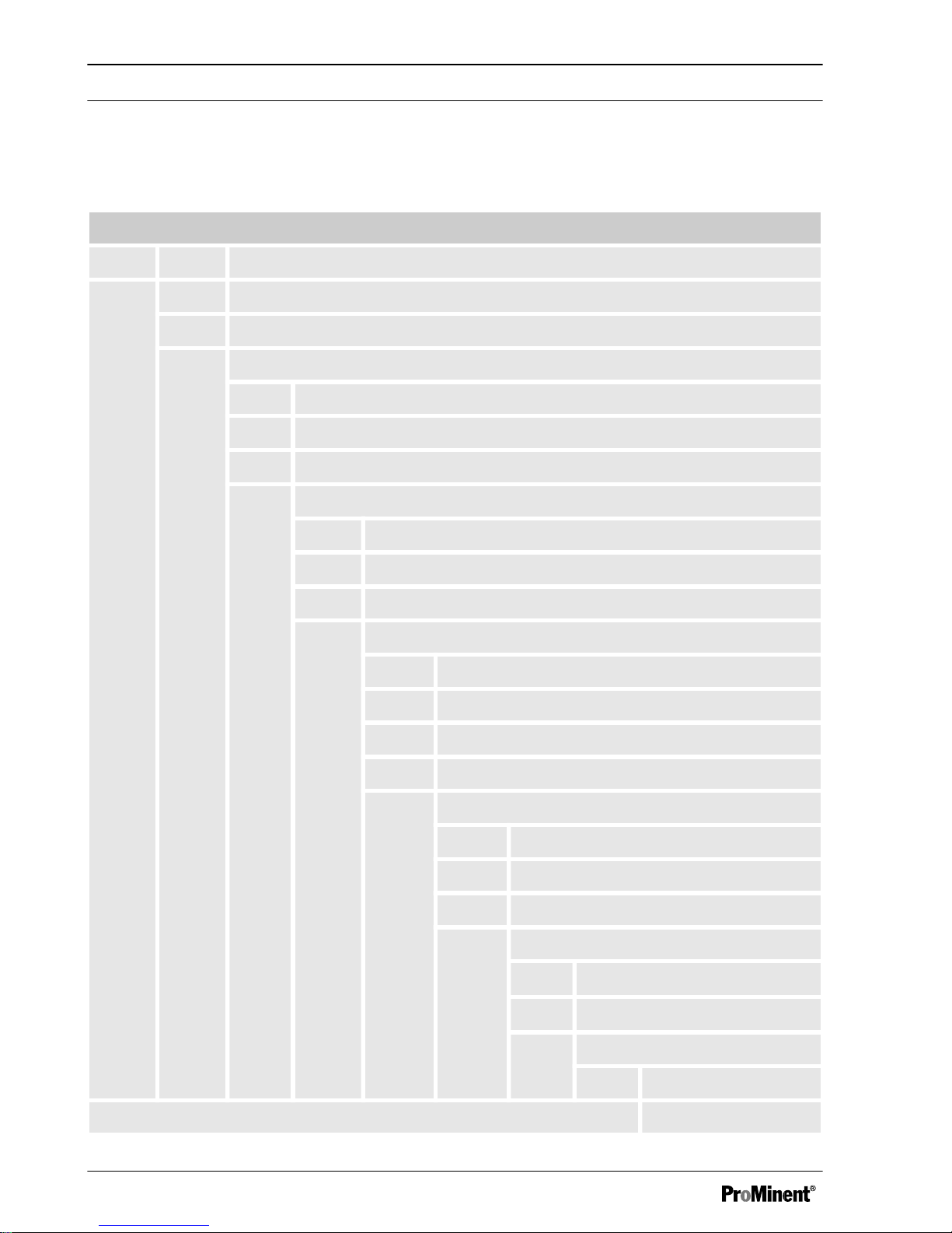
1 Identity code
Product range DulcoFlow® flow meter
DFMa Type For pump product ranges
05 Beta, gamma/ L: 1000 - 0413/0713; delta: 1608 - 1612
08 Beta, gamma/ L: 0220/0420 - 0232; delta: 1020 - 0280
Seal material
E EPDM
T PTFE
V FPM
Hydraulic connection
1 6/4 mm
2 8/5 mm
3 12/9 mm
Electrical connection
A 2 m European
B 2 m Swiss
C 2 m Australian
D 2 m USA
Signal output
0 No output
1 Current output
2 Counter output
Version
0
With ProMinent®
Logo
2
Without ProMinent® Logo
Accessories
0 No accessories
Identity code
6
Page 7

Identity code
7
Page 8

2 About this product
The flow meter DulcoFlow® is intended for use
in measuring pulsing volume flows in the range
from 0.1 to 80 l/h. All parts coming into contact
with flow media are made from PVDF. This
ensures that aggressive media can also be
measured without problem. The device is
installed approximately 30 cm after the pump in
the metering line. Interfering influences, such
as air bubbles, are identified and forwarded to
the analysis unit as an error message. With the
delta, it can only be used with the fast metering
stroke version.
The DulcoFlow® flow meter can not only be
used for recording and measurement of volume
flows, but also for monitoring individual
metering strokes. In this case the pump is cali‐
brated to the lifting volume set at the pump. A
lower and upper limit can be entered, which if
exceeded or undershot, results in no feedback
to the pump. This creates an error message.
The connection to the pump takes place via the
input for the "Flow Control" dosing monitor
The device is designed for wall mounting.
About this product
8
Page 9
3 Safety chapter
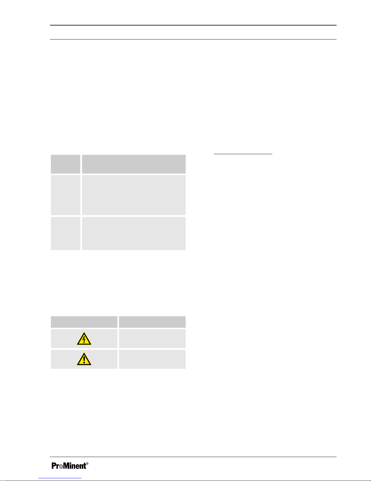
Explanation of the safety information
The following signal words are used in these
operating instructions to identify different
severities of a hazard:
Signal
word
Meaning
WARNINGDenotes a possibly hazardous sit‐
uation. If this is disregarded, you
are in a life-threatening situation
and this can result in serious inju‐
ries.
CAU‐
TION
Denotes a possibly hazardous sit‐
uation. If this is disregarded, it
could result in slight or minor inju‐
ries or material damage.
Warning signs denoting different types of
danger
The following warning signs are used in these
operating instructions to denote different types
of danger:
Warning signs Type of danger
Warning – highvoltage.
Warning – danger
zone.
Correct and proper use
n The device may only be used with liquid
metering chemicals.
n The device can only be used with pulsing
liquid flows with a clear zero flow.
n The device may only be used after it has
been correctly installed and commissioned
in accordance with the technical data and
specifications contained in the operating
instructions.
n Observe the general limitations with regard
to viscosity limits, chemical resistance and
density - see also ProMinent resistance list
(In the product equipment catalogue or at
www.prominent.com
)!
n Any other uses or modifications are pro‐
hibited.
n The device is not suitable for measuring
continuous liquid flows.
n The device may not be used to measure
gaseous media or solids.
n The device may not be used with combus‐
tible media without appropriate protective
measures.
n The device may not be used with explo‐
sive media.
n The device may not be used with radioac‐
tive media.
n The device is not intended for exterior
applications without use of suitable protec‐
tive equipment.
n The device should only be operated by
trained and authorised personnel, see the
following "Qualifications" table.
n You are obliged to observe the information
contained in the operating instructions at
the different phases of the system's
service life.
Safety chapter
9
Page 10
Safety information
WARNING!
Danger of electric shock
A mains voltage may exist inside the
housing.
– If the housing has been damaged,
you must disconnect the device from
the mains immediately. It may only be
returned to service after an authorised
repair.
WARNING!
Warning of dangerous or unknown feed
chemical
Should a dangerous or unknown feed
chemical be used: It may escape from the
hydraulic components during maintenance
work.
– Take appropriate protective measures
before working on the device (safety
glasses, safety gloves, ...). Observe
the safety data sheet for the feed
chemical.
–
Drain and flush the hydraulic parts
before working on the device.
CAUTION!
Warning of feed chemical spraying around
Feed chemical can spray out of the
hydraulic components if they are manipu‐
lated or opened due to pressure in the
hydraulic and adjacent parts of the system.
– Disconnect the pump of the device
hydraulic system from the mains
power supply and ensure that it
cannot be switched on again by unau‐
thorised persons.
– Depressurise the system before com‐
mencing any work on hydraulic parts.
CAUTION!
Danger of personnel injury and material
damage
The use of untested third party parts can
result in personnel injuries and material
damage.
– Only fit parts to the device, which
have been tested and recommended
by ProMinent.
NOTICE!
Warning of illegal operation
Observe the regulations that apply where
the device is installed.
Information in the event of an emergency
In an emergency, disconnect the device from
the mains!
If feed chemical escapes, also depressurise the
device hydraulic system. Adhere to the safety
data sheet for the feed chemical.
Safety chapter
10
Page 11

Qualification of personnel
Activity Qualification level
Storage, transport,
unpacking
Instructed personnel
Installation, installa‐
tion of hydraulic
system
Technical personnel
Electrical installation Electrician
Operation Instructed personnel
Maintenance Technical personnel
Repairs Customer service -
authorised by ProMi‐
nent
Decommissioning,
disposal
Technical personnel
Troubleshooting Technical personnel,
electrician, instructed
personnel
Technical personnel
A qualified employee is deemed to be a person
who is able to assess the tasks assigned to him
and recognise possible hazards based on his/
her technical training, knowledge and experi‐
ence, as well as knowledge of pertinent regula‐
tions.
Electrician
Electricians are deemed to be people, who are
able to complete work on electrical systems
and recognize and avoid possible hazards
independently based on their technical training
and experience, as well as knowledge of perti‐
nent standards and regulations. Electricians
should be specifically trained for the working
environment in which the are employed and
know the relevant standards and regulations.
Electricians must comply with the provisions of
the applicable statutory directives on accident
prevention.
Instructed personnel
An instructed person is deemed to be a person
who has been instructed and, if required,
trained in the tasks assigned to him/her and
possible dangers that could result from
improper behaviour, as well as having been
instructed in the required protective equipment
and protective measures.
Customer Service department
Customer Service refers to service technicians,
who have received proven training and have
been authorised by ProMinent® to work on the
system.
Safety chapter
11
Page 12
4 Storage and transport
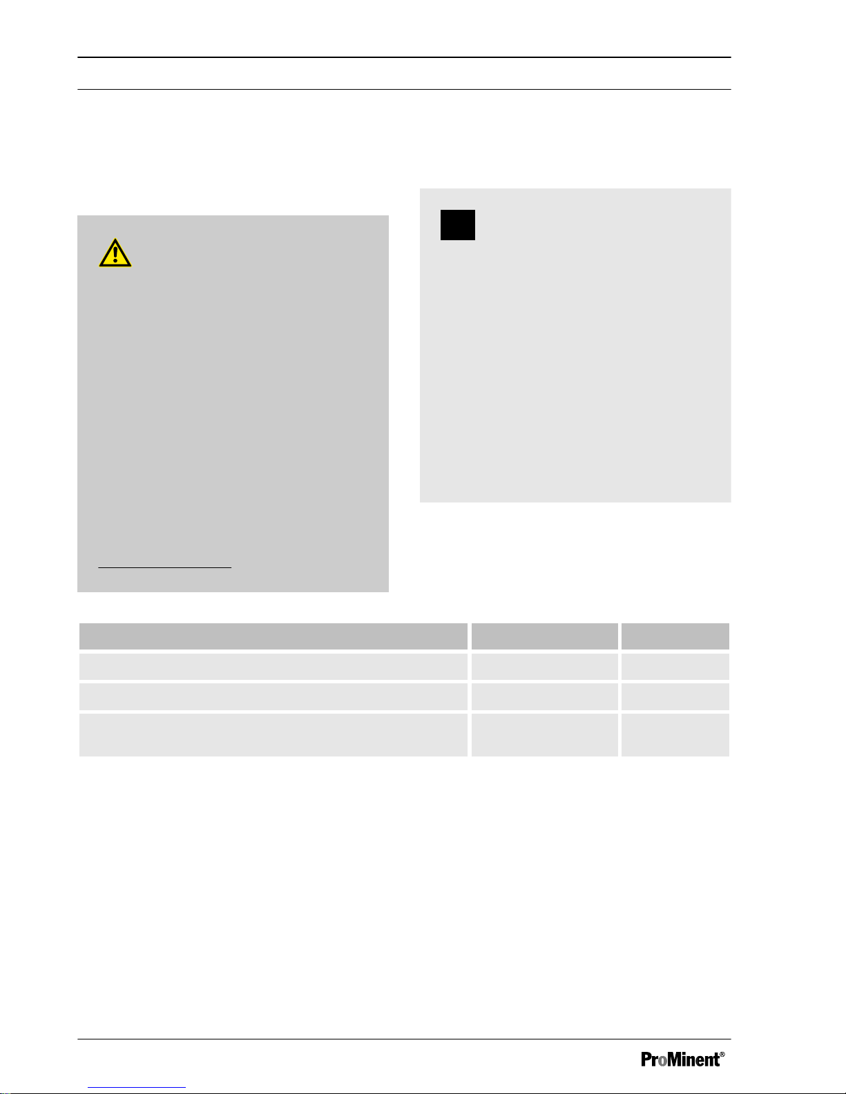
Safety information
WARNING!
Only return the device for repair in a
cleaned state and with flushed hydraulic
parts - refer to the chapter "Decommis‐
sioning"!
Only send the unit complete with a filled in
Decontamination Declaration form. The
Decontamination Declaration constitutes
an integral part of an inspection / repair
order. A unit can only be inspected or
repaired when a Decontamination Declara‐
tion Form is submitted that has been com‐
pleted correctly and in full by an authorised
and qualified person on behalf of the oper‐
ator.
The "Decontamination Declaration Form"
can be found in the Appendix or under
www.prominent.com
.
NOTICE!
Danger of material damage
The device can be damaged by incorrect
or improper storage or transportation!
– The device should only be stored or
transported in a well packaged state preferably in its original packaging.
– The packaged unit should also only
be stored or transported in accord‐
ance with the stipulated storage con‐
ditions.
– The packaged unit should be pro‐
tected from moisture and the ingress
of chemicals.
Ambient conditions
Data Value Unit
Minimum storage and transport temperature -10 °C
Maximum storage and transport temperature +50 °C
Air humidity < 95 % rel.
humidity*
* non-condensing
Storage and transport
12
Page 13
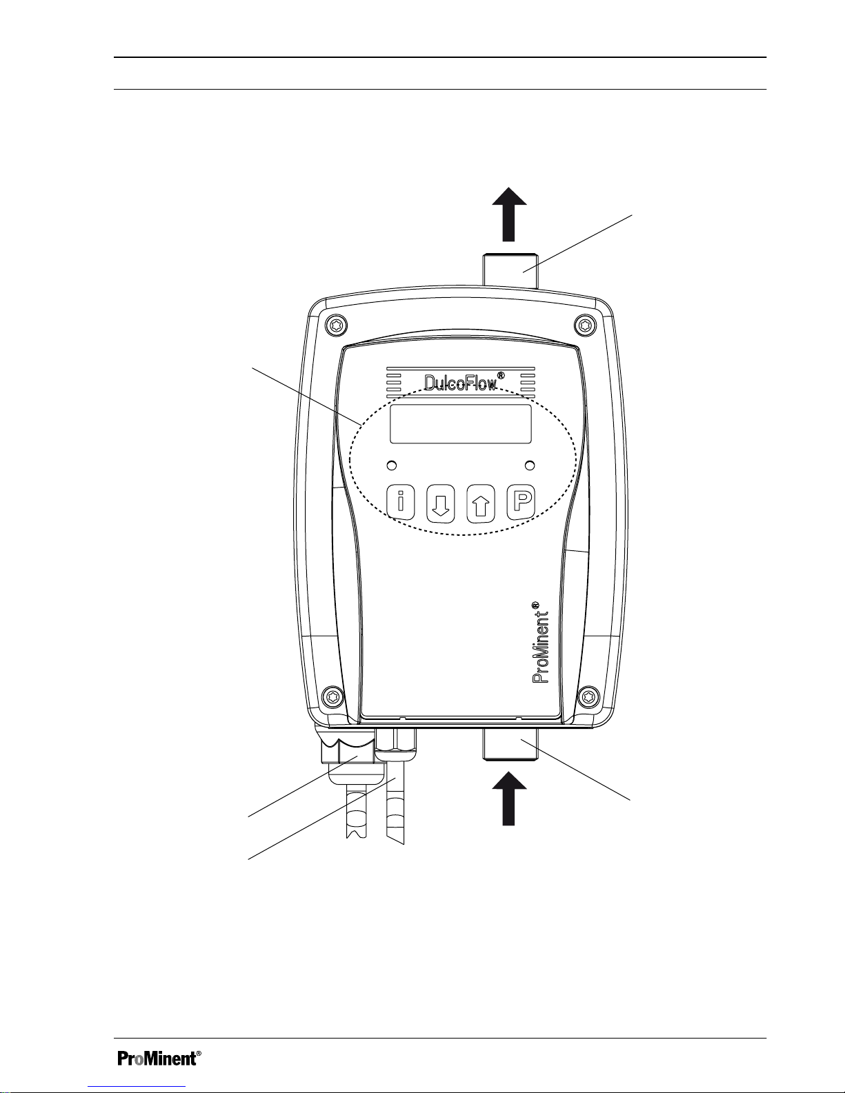
5 Device overview
1
2
4
5
3
Fig. 1: Overview of equipment DulcoFlow® with arrows showing flow
1 Control elements - see chapter "Settings" -
"Operating unit"
2 Mains connection
3 Signal output (option)
4 Feed chemical inlet
5 Feed chemical outlet
Device overview
13
Page 14

6 Functional description
The DulcoFlow ® flow meter measures the
volume flow of pulsing flows. The ultrasonic,
time of flight measurement method is used. For
the time of flight measurement, a sound signal
is alternately transmitted in and against the
direction of flow. The time difference is then a
measure of the mean flow velocity. Use of the
ultrasound measurement method automatically
compensates any temperature induced
changes in the medium. Operation without
moving parts guarantees a long service life and
wear-free operation.
The DulcoFlow® calculates the mass flow from
the volume flow and the density of the feed
chemical.
Additionally the DulcoFlow® can measure the
pressure surges of the metering pump and
hence replace a dosing monitor such as the
Flow Control. A metering pump such as the
gamma/ L or delta®
can use these signals as
acknowledge pulses for its individual strokes. If
the acknowledge pulses are missing or if the
capacity exceeds the specified limit values, the
metering pump stops after an adjustable
number of missing pulses and goes into fault
mode - see metering pump operating instruc‐
tions.
The DulcoFlow® gives the flow reading, stroke
feedback, or error messages via the various
output types.
Functional description
14
Page 15
7 Assembly and installation
Safety information
WARNING!
Carry out the assembly work before the
electrical installation is undertaken.
WARNING!
Observe the information in the "Technical
data" chapter.
WARNING!
Danger of an electric shock
If the device is used outdoors without a
cover or weatherproof roof, water may be
able to collect on the seals and penetrate
the housing or direct sunlight may cause
the housing to be corroded.
– Always use a cover or weatherproof
roof when using the unit outdoors.
CAUTION!
Warning of illegal operation
Observe the regulations that apply where
the unit is to be installed.
The device is resistant to normal atmos‐
pheres in plant rooms.
7.1 Installation
Install the device so that the hose between
it and the pump is approximately 30 cm
long.
This ensures it measures accurately.
Mount the device vertically.
This ensures it measures accurately.
Mount the device vertically on the wall
using both eyes on the housing.
Do not forget the washers.
7.2 Hydraulic Installation
CAUTION!
Warning of escaping feed chemical
Feed chemicals can escape in the event
that the hose lines are incorrectly installed.
– Only use original hoses with the
specified hose dimensions.
– Avoid reducing the hose sizes.
Assembly and installation
15
Page 16
Flow direction
The flow direction through the device goes
from the bottom to the top.
Injection valves, back pressure
valves, relief valves
Injection valves, back pressure valves or
relief valves must not have any effect on
the measurement.
Relief valves
It is best to install a relief valve before the
flow meter, so that the displayed flow or
flow volume actually corresponds to the
value which is being metered into the
system if the relief valve triggers.
Hydraulic Dampers
Hydraulic dampers, like accumulators,
inline dampers or bladder accumulators /
diaphragm accumulators must not have
any effect on the measurement.
A zero flow must be available.
The damping must not push the flow mean
value beneath the measurement threshold.
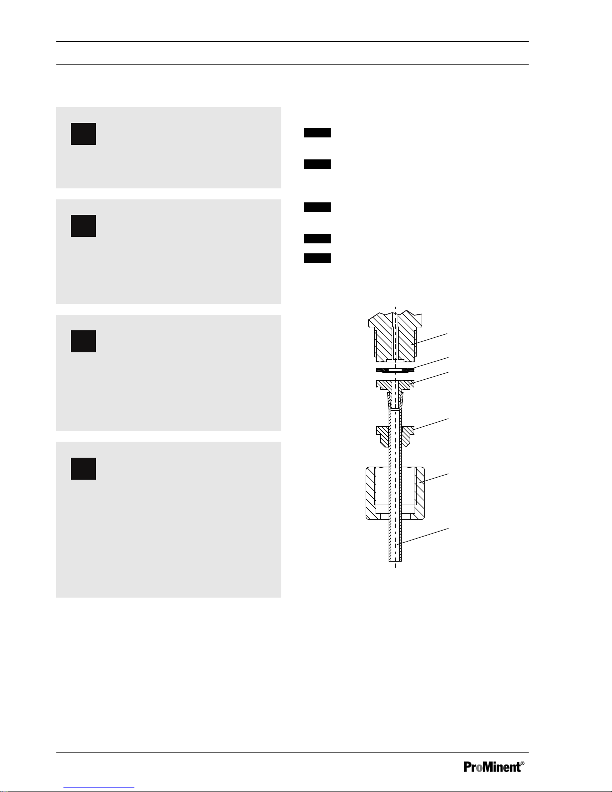
Installing the hosing:
1. Cut off the ends of the hoses (6) so that
they are straight.
2. Unscrew the union nut (5) and push
over the hose together with the clamp
ring (4).
3. Push the hose end (6) up to the stop
over the nozzle (3).
4. Tighten the union nut (5).
5. Pull on the hose (6) and tighten up the
union nut (5).
1
3
2
4
5
6
P_MAZ_0041_SW
Fig. 2: Installing the hose line
1 Connector
2 Seal
3 Nozzle
4 Clamp ring
5 Union nut
6 Hose
Assembly and installation
16
Page 17
P_MAZ_0040_SW
2
PD
1
3
4
5
6
7
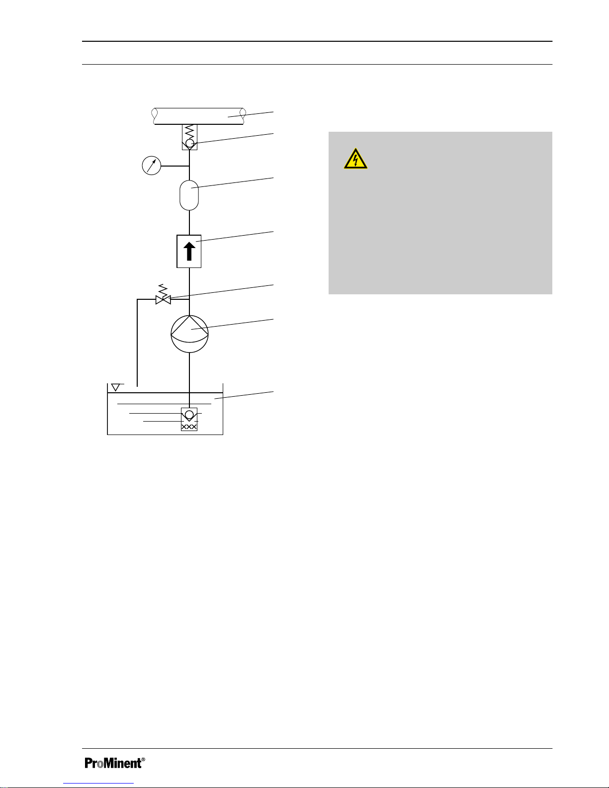
Fig. 3: DulcoFlow® hydraulic system
1 Target use
2 Pressure maintenance device
3 Hydraulic Damper
4
DulcoFlow
®
5 Overflow device
6 Metering pump
7 Storage tank
7.3 Electrical Installation
WARNING!
Danger of electric shock
The use of a residual current circuit
breaker drastically increases survival
chances should persons come into contact
with the mains voltage due to an electrical
accident.
– Always fit a residual current circuit
breaker on-site.
A metering pump, PLC or other devices can be
connected to the flow meter.
The following alternative electrical outputs are
available via cable:
n Current output (identity code characteristic
"signal output "1"):
n Counter output (identity code characteristic
"signal output "2"):
Assembly and installation
17
Page 18
Current output
The following can be signalled via the current output (standard signal output (mA)):
n Instantaneous flow
n Fault
Technical data:
Data Value Unit
Current* 0/4 .. 20 mA
Maximum load 400 Ω
* zero volt connection
Counter output as stroke feedback output
The counter output as stroke feedback output
can be used to signal stroke feedback, pro‐
vided it is set accordingly - see chapter "Set‐
tings".
1. To report stroke feedback at the
metering pump such as gamma/ L and
delta® , plug the cable from the flow
meter to the pump in the "dosing mon‐
itor" terminal.
ð
The identifier for the dosing monitor
must appear on the LCD screen of
the pump.
2. If it does not appear, make the neces‐
sary settings at the metering pump.
Assembly and installation
18
Page 19

Counter output as frequency output
The counter output as frequency output can be used to signal flow or an error, provided it is set
accordingly - see chapter "Settings".
1. Remove the connected socket.
2. Remove the insulation of the leads to match the terminals of the other device.
3. Crimp on a suitable cable end sleeve.
ð
In this format, the cable can be connected to another device.
4.
Connect the cable to both devices in accordance with the wiring diagram. DulcoFlow® wiring
diagram - see appendix.
Technical data:
Data Value Unit
Voltage with open contacts < 30 V
Current with closed contacts < 10 mA
Residual voltage with closed contacts < 0.7 V
Switching frequency < 10 kHz
Lead Function
brown Supply Voltage
white Error signal
blue Frequency signal
black Mass
Assembly and installation
19
Page 20

8 Settings
8.1 Operating unit
P_MAZ_0039_SW
V: 1145.69 mL
Q:
502.13
mL/h
i
DulcoFlow
®
1
2
3
4
Fig. 4: Operating unit DulcoFlow
®
1 LCD display
2 Status LED
3 Control keys
4 Stroke feedback LED
8.1.1 LCD screen
The LCD screen comprises a two-line display.
8.1.2 LEDs
The status LEDs (left) shows the following
information:
LED Information
green Status OK
orange Warning
red Error
The stroke feedback LED (right) shows the fol‐
lowing information:
LED Information
off No pressure surge identified
green, illumi‐
nated
Pressure surge detected within tolerance
red, illumi‐
nated
Pressure surge detected outside tolerance
8.1.3 Control keys
The control keys are designated as follows:
Key Designation
i
[ i ]
[DOWN]
[UP]
[P]
Settings
20
Page 21

P
P
3 s
P
P
3 s
cont.
display
main menu
set-up
set-up
display
= set-up
option
Fig. 5: Navigation within the operating menu
The control keys have different functions in the continuous display, in the operating menu and in the
menu branches.
In the continuous display
Key Functions
i
Changes to continuous dis‐
play
Changes into the operating
menu
In the operating menu
Key Functions
Change to the previous menu
branch
Change to the next menu
branch
Open menu branch (switch to
the first item of the selected
menu branch).
Settings
21
Page 22

In a menu item of a menu branch
Key Functions
i
Switches between the continuous changing of a number and digit
by digit changing
Increase/change the set value
Reduce/change the set value
Accept the configured value and change to the next menu item of
the menu branch.
In digit by digit changing: Within a number change to the next
figure.
B0210
density
1.3425 g/mL
density
1.3425 g/mL
density
1.3425 g/mL
a) b)
Fig. 6: a) Change between continuous changing of a number and digit by digit changing; b) Changes
the position within the number
Key [P] - additional generally-applicable func‐
tions:
Press dura‐
tion
Function
approx. 2 s Open the operating menu
approx. 3 s Quit the operating menu
without saving the configured
values and return to the con‐
tinuous display
A modified set value is only adopted, if it
has previously been confirmed by brief
pressing of the [P] key.
Settings
22
Page 23

8.2 Checking adjustable varia‐
bles
Before you adjust the flow meter, you can
check the actual settings of the adjustable vari‐
ables:
Press the key
[ i ]
("i" for "Info"), if the
LCD screen is displaying a continuous
display - i.e. no display of the operating
menu.
ð
After every press on the
[ i ]
key,
you see a different continuous dis‐
play.
The number and appearance of the continuous
displays depends on the selected measured
variable and whether a setpoint has been
entered - see below.
The key [ i ] is used to change between
continuous displays.
Continuous display for the "Volume" measured
variable
Continuous display Description
V: 243,32 mL
Q: 171,05 mL/h
Total quantity* V and
instantaneous volume
flow Q
V: 243,32 mL
N: 637
Total quantity* V and
number of strokes* N
V/H: 0,382 mL
%SH: 102,3 %
Volume per stroke V/
H and deviation from
the set point of the
lifting volume** %SH
* since the last reset
** if a
„volume (stroke)“
has been entered under
„Calibration è Stroke feedback è Set-point“
Continuous displays for the "Mass" measured
variable
(If
„mass“
was set under
„Mode
è
Measured variable“
.)
Continuous display Description
m: 326,05 g
Q: 229,21 g/h
Total quantity* m and
instantaneous mass
flow Q
m: 326,05 g
N: 527
Total quantity* m and
number of strokes* N
m/H: 0,619 g
%SH: 97,8 %
Mass per stroke m/H
and deviation from the
set point of the stroke
mass** %SH
* since the last reset
** if a
„mass (stroke)“
has been entered under
„Calibration è Stroke feedback è Set-point“
Reset values
–
To reset the total quantity and
strokes, press both [arrow keys]
simultaneously.
–
In the main menu "Zero set", the total
quantity and the strokes can be set to
"zero" independently of each other.
Settings
23
Page 24

8.3 Operating menu overview
B0209
P
P
P
cont.
display
2 s
set to zero quantity and strokes
acknowledge error
main menu
mode
menu
measurandmeasurand
P
main menu
calibrationcalibration
menu
stroke feedb.stroke feedb.
menu
quantityquantity
P
main menu
zero setzero set
menu
quantityquantity
menu
strokesstrokes
P
main menu
set-upset-up
menu
displaydisplay
menu
serviceservice
menu
counter outp.*counter outp.*
menu
current output*current output*
* Dependent on identity code
Settings
24
Page 25

main menu
infoinfo
main menu
languagelanguage
Fig. 7
8.4 Changing to adjustment
mode
If the
[P]
key is pressed for 2 seconds in a con‐
tinuous display, the device changes to adjust‐
ment mode.
The following main menus can be selected in
adjustment mode:
1 - Mode
2 - Set-up
3 - Calibration
4 - Zero set
5 - Info
6 - Language
8.4.1 "Mode" main menu
main menu
mode
The measured variables can be selected from
the "Operation" main menu:
n
„Volume“
(-flow)
n
„Mass“
(-flow)
The appearance of a few menus is dependent
on this.
8.4.2 "Set-up" main menu
main menu
set-up
The following menus can be selected from the
"set-up" main menu:
1 -
„Display“
3 -
„Current output“
(identity code character‐
istic "signal output" "1")
2 -
„Counter output“
(identity code character‐
istic "signal output" "2")
4 -
„Service“
(for customer service only)
Settings
25
Page 26

8.4.2.1 "Display" menu
P P P P
B0228
set-up
display
flow unit
mL/h
quantity unit
mL
damping flow
30.00
s
In the
„display“
menu, the units can be selected for the quantities and flow.
Moreover, the damping of the displayed flow values can be changed (not for quantities), if they
change too quickly / slowly in the display.
The greater the set integration constant in the menu item
„damping flow“
, the greater the damping of
the displayed flow values.
Non-metric units and their conversion
Unit Meaning Conversion
1 gal 1 US liquid gallon = 3.785421 l
1 lb(s) 1 Pound = 453.59237 g
8.4.2.2 "Counter output" menu
(identity code characteristic "signal output" "2")
P
P
P
P P
P
P P
P P
B0235
set-up
counter output
puls/freq.
open-collector
counter output
puls/freq.
counter output
stroke feedback
open-collector
NPN
K factor
5000 1/mL
puls/freq.
signal
output
K factor unit
1/mL
puls/freq.
error output
error
bubbles
In the
„counter output“
menu the counter output can be set either as a pulse/frequency output to
output the instantaneous flow, as an error signal or as a feedback message.
Settings
26
Page 27

puls/freq. (frequency output)
Firstly the type of the output (
„Open-Collector“
)
can be selected so that it is suitable for the con‐
nected device (NPN / PNP).
The K factor can be set via the
„signal output“
menu, and is then used by the DulcoFlow® to
convert the instantaneous flow prior to output
via the counter output to an external device.
In the
„error output“
menu a setting can be
made to determine whether the DulcoFlow
®
outputs an error signal via the counter output to
an external device. It works like a relay in
status NO.
stroke feedback
For stroke feedback, e.g. to a Prominent
metering pump, as with a Flow Control® dosing
monitor, the cable must be fed from the counter
output to the "dosing monitor" terminal of the
metering pump.
Then the
„stroke feedback“
must be calibrated
under
„calibration“
, see chapter "Calibration".
Settings
27
Page 28

8.4.2.3 "Current output" menu
(identity code characteristic "signal output" "1")
P P P P
P P
P P
B0234
set-up
current output
current range
4...20 mA
current output
signal current
flow unit
mL/h
0/4 mA value
0.68 mL/h
20 mA value
897.65 mL/h
current output
error current
error current
bubbles
In the
„current output“
menu the standard signal output (mA) can be set either to output the instanta‐
neous flow or as a feedback message.
In the
„signal current“
menu a setting can be
made to determine how the DulcoFlow® outputs
the instantaneous flow via the current output to
an external device.
In the
„error output“
menu a setting can be
made to determine whether the DulcoFlow
®
outputs an error signal via the current output to
an external device (23 / 3.6 mA).
Settings
28
Page 29

8.4.2.4 "service" menu
P P
B0229
set-up
service
service code
0000
The "service" menu is password protected and only for customer service.
8.4.3 "Calibration" main menu
main menu
calibration
From the "calibration" menu either the flow
measurement can be calibrated or the stroke
feedback set up.
8.4.3.1
Calibrate "stroke feedback"
8.4.3.1.1
For "volume"
The permitted range for the lifting volume V/H
can be specified in this menu. If the lifting
volume moves outside of this range, e.g. due to
a changed back pressure, the DulcoFlow® no
longer gives any stroke feedback to the
metering pump and the right LED now illumi‐
nates as a steady red instead of green. ProMi‐
nent metering pumps such as the gamma/ L or
delta® go into fault mode after a series of defec‐
tive strokes (pump set up).
Settings
29
Page 30

About setpoint and tolerances
P P P P
P P P
B0230
calibration
stroke feedback
volume (stroke)
0.347 mL
stroke feedback
set-point
volume
(stroke)
0.347 mL
lower tolerance
-010.00 %
tolerance
tolerance (%)
upper tolerance
+020.00
%
Specify the allowed range for the lifting volume V/H via the setpoint of the lifting volume V/H and
tolerances in %:
1.
Follow the menu path
„calibration è stroke feedback è set-point“
and press the key
[P]
.
ð
The menu item
„volume (stroke)“
displays the currently stored setpoint.
2. Start the metering pump.
ð
The actual measured value is displayed.
3. Turn the stroke length adjustment knob until the desired setpoint is displayed.
4. Press key
[P]
.
ð
The displayed measured value is saved as a setpoint and the menu item
„tolerance
tolerances“
appears.
The setpoint is valid as 100%.
5. Stop the metering pump.
6. Press key
[P]
.
7. Set the
„lower tolerance“
with the
[arrow keys]
and press the
[P]
.
8. Set the
„upper tolerance“
with the
[arrow keys]
and press the
[P]
.
ð
The continuous display appears again.
The desired setpoint can also be entered, without having to use the stroke adjustment dial or
the pump having to be running, directly under „volume (stroke)“ using the [arrow keys] .
Settings
30
Page 31

Upper limit values
B0231
calibration
stroke feedback
volume (stroke)
0.347 mL
stroke feedback
set-point
P P P P
volume (stroke)
0.347 mL
tolerance
tolerance (%)
P
lower limit
0.312 mL
tolerance
limits
P P P
upper limit
0.416
mL
Alternatively, the desired limits for the allowed range of the lifting volume can be entered under
„lower limit“
and
„upper limit“
:
1.
Follow the menu path
„calibration è stroke feedback è set-point“
and press the key
[P]
.
ð
The menu item
„volume (stroke)“
displays the currently stored setpoint.
2. Start the metering pump.
ð
The actual measured value is displayed.
3. Turn the stroke length adjustment knob until the desired setpoint is displayed.
4. Press key
[P]
.
ð
The displayed measured value is saved as a setpoint and the menu item
„tolerance
tolerances“
appears.
The setpoint is valid as 100%.
5. Using the
[arrow keys]
change to the menu item
„limits“
and press key
[P]
.
6. Turn the stroke length adjustment dial down until the desired lower limit is reached and press
key
[P]
.
7. Proceed analogously for the upper limit.
ð
The continuous display appears again.
8. Stop the metering pump.
Settings
31
Page 32

The desired setpoint can also be entered, without having to use the stroke adjustment dial or
the pump having to be running, directly under „volume (stroke)“ using the [arrow keys] .
8.4.3.1.2 For "mass"
The permitted range for the mass per stroke m/
H can be specified in this menu. If the mass per
stroke moves outside of this range, e.g. due to
a changed back pressure, the DulcoFlow® no
longer gives any stroke feedback to the
metering pump and the right LED now illumi‐
nates as a steady red instead of green. ProMi‐
nent metering pumps such as the gamma/ L or
delta® go into fault mode after a series of defec‐
tive strokes (pump set up).
Settings
32
Page 33

About setpoint and tolerances
B0232
P P P P
P P P
calibration
stroke feedback
mass (stroke)
0.347 g
stroke feedback
set-point
mass (stroke)
0.347 g
lower
tolerance
-010.00
%
tolerance
tolerance (%)
upper tolerance
+020.00 %
Specify the allowed range for the mass per stroke m/H via the setpoint of the lifting volume m/H and
tolerances in %:
1.
Follow the menu path
„calibration è stroke feedback è set-point“
and press the key
[P]
.
ð
The menu item
„volume (stroke)“
displays the currently stored setpoint.
2. Start the metering pump.
ð
The actual measured value is displayed.
3. Turn the stroke length adjustment knob until the desired setpoint is displayed.
4. Press key
[P]
.
ð
The displayed measured value is saved as a setpoint and the menu item
„tolerance
tolerances“
appears.
The setpoint is valid as 100%.
5. Press key
[P]
.
6. Set the
„lower tolerance“
with the
[arrow keys]
and press the
[P]
.
7. Set the
„upper tolerance“
with the
[arrow keys]
and press the
[P]
.
ð
The continuous display appears again.
8. Stop the metering pump.
The desired setpoint can also be entered, without having to use the stroke adjustment dial or
the pump having to be running, directly under „mass (stroke)“ using the [arrow keys] .
Settings
33
Page 34

Upper limit values
B0233
P P P P
P
P P P
calibration
stroke feedback
mass (stroke)
0.347 g
stroke feedback
set-point
mass (stroke)
0.347 g
tolerance
tolerance (%)
lower
limit
0.312 g
tolerance
limits
upper
limit
0.416 g
Alternatively, the desired limits for the allowed range of the stroke mass can be entered under
„lower
limit“
and
„upper limit“
:
1.
Follow the menu path
„calibration è stroke feedback è set-point“
and press the key
[P]
.
ð
The menu item
„volume (stroke)“
displays the currently stored setpoint.
2. Start the metering pump.
ð
The actual measured value is displayed.
3. Turn the stroke length adjustment knob until the desired setpoint is displayed.
4. Press key
[P]
.
ð
The displayed measured value is saved as a setpoint and the menu item
„tolerance
tolerances“
appears.
The setpoint is valid as 100%.
5. Using the
[arrow keys]
change to the menu item
„limits“
and press key
[P]
.
6. Turn the stroke length adjustment dial down until the desired lower limit is reached and press
key
[P]
.
7. Analogously, proceed in the same way for the upper limit.
ð
The continuous display appears again.
8. Stop the metering pump.
Settings
34
Page 35

The desired setpoint can also be entered, without having to use the stroke adjustment dial or
the pump having to be running, directly under „mass (stroke)“ using the [arrow keys] .
8.4.3.2 Calibrate "quantity"
Only calibrate the quantity flow if the dis‐
played values do not attain the expected
accuracy.
Settings
35
Page 36

8.4.3.2.1 By corr. factor
B0244
P P P
calibration
quantity
corr. factor
101.23 %
quantity
corr. factor
calibration
stroke
feedback
If the new correction factor is know in %, it can be entered directly here.
It is obtained by dividing a value you have measured yourself by the displayed value and multiplying
the result by 100.
1.
Follow the menu path
„calibration è stroke feedback“
.
2. Using the
[arrow keys]
change to the menu item
„calibration quantity“
and press key
[P]
2x.
3. Using the
[arrow keys]
Enter the
„corr. factor“
and press the key
[P]
.
ð
The continuous display appears again.
8.4.3.2.2 By meas. Value
CAUTION!
Danger with dangerous feed chemicals
Provided the following handling instruc‐
tions are followed, contact with the feed
chemical is possible.
– If the feed chemical is dangerous,
take appropriate safety precautions
when carrying out the following han‐
dling instructions.
–
Observe the feed chemical safety
data sheet.
Depending on the set measured variable, a cal‐
ibration menu appears for:
n Volume
n Mass
Settings
36
Page 37

Volume
B0226
P P
P P P
P
calibration
quantity
quantity
corr. factor
actual volume
54.72 mL
quantity
meas. Value
corr. factor
95.27 %
nominal volume
52.13 mL
calibration
stroke feedback
Settings
37
Page 38

Requirements:
n 1 measuring cylinder which can be read sufficiently accurately
n The metering pump suction line is fed, bubble-free into the measuring cylinder.
1. Record the fluid level in the measuring cylinder.
2. Change from the menu item
„calibration stroke feedback“
using the
[arrow keys]
to the menu
item
„calibration quantity“
and press key
[P]
.
ð
The menu item
„quantity corr. factor“
appears.
3. Change from the menu item
„quantity corr. factor“
using the
[arrow keys]
to the menu item
„quantity meas. Value“
and press key
[P]
.
ð
The menu item
„actual volume“
appears.
4. Start the metering pump.
Select the number of strokes so that the reading error at the measuring cylinder (half of
the smallest readable volume graduation divided by the metered total volume) is smaller
than the Dulcoflow measurement error.
5. Stop the metering pump.
6. Record the fluid level in the measuring cylinder and calculate the difference.
7. Press key
[P]
.
ð
The menu item
„nominal volume“
appears.
8. Adjust the value in the menu item
„nominal volume“
using the
[arrow keys]
based on this dif‐
ference and press the
[P]
key.
ð
The menu item
„corr. factor“
appears. It shows the calculated correction factor.
9. Press key
[P]
, to return to the continuous display.
It is also possible to manually calculate the correction factor and enter it directly under
„entry“
-
„corr.
factor“
.
Settings
38
Page 39

Mass
B0227
P P
P P P
P
calibration
quantity
quantity
corr. factor
actual mass
54.72 g
quantity
meas. Value
corr. factor
95.27 %
nominal mass
52.13 g
calibration
stroke feedback
Settings
39
Page 40

Requirements:
n 1 weighing instrument which can be read sufficiently accurately
n 1 vessel with feed chemical
n the suction line is fed, bubble-free into the measuring vessel.
1. Zero the weighing instrument.
2. Change from the menu item
„calibration stroke feedback“
using the
[arrow keys]
to the menu
item
„calibration quantity“
and press key
[P]
.
ð
The menu item
„quantity corr. factor“
appears.
3. Change from the menu item
„quantity corr. factor“
using the
[arrow keys]
to the menu item
„quantity meas. Value“
and press key
[P]
.
ð
The menu item
„actual mass“
appears.
4. Start the metering pump.
Select the number of strokes so that the reading error at the weighing instrument (half of
the smallest readable mass graduation divided by the metered total mass) is smaller
than the Dulcoflow measurement error.
5. Stop the metering pump.
6. Read off the weight from the weighing instrument.
7. Press key
[P]
.
ð
The menu item
„nominal mass“
appears.
8. Adjust the value in the menu item
„nominal mass“
using the
[arrow keys]
to the read-off
weight and press the key
[P]
.
ð
The menu item
„corr. factor“
appears. It shows the calculated correction factor.
9. Press key
[P]
, to return to the continuous display.
It is also possible to manually calculate the correction factor and enter it directly under
„entry“
-
„correction factor“
.
8.4.4 "Zero set" main menu
main menu
zero set
In the main menu "Zero set", the total quantity
and the strokes, which are displayed in the con‐
tinuous display, can be set to "zero" independ‐
ently of each other.
Settings
40
Page 41

8.4.5 "Info" main menu
main menu
info
This information can be read-off in the "info"
main menu:
Code Meaning
ID Identity code
SN Serial number
HW Hardware version
SW Software version
BL Bootloader
8.4.6 "Language" main menu
main menu
language
The operating language can be selected from
the "language" main menu.
Settings
41
Page 42

9 Start up
1. Connect the device hydraulically to the
installation.
2. Connect the device to the supply
voltage.
3. If necessary set:
n the language - see
Ä Chapter 8.4.6
„"Language" main
menu“ on page 41
n the measured variable to "mass"
and density of the feed chemical see
Ä on page 25
n the units - see
Ä Chapter 8.4.2.1
„"Display" menu“ on page 26
n the current output - see
Ä Chapter
8.4.2.3 „"Current output"
menu“ on page 28
n the counter output - see
Ä Chapter
8.4.2.2 „"Counter output"
menu“ on page 26
4. Allow the metering pump to prime press both
[arrow keys]
simultaneously
at the pump control unit.
5. At the device acknowledge the error
„bubbles“
by pressing the key
[P]
.
6. Allow the metering pump to run.
7. Check whether the displayed values are
plausible.
8. Check whether the stroke feedback to
the metering pump is plausible.
9. Check whether the frequency signals
and the mA signals of the device have
the expected effect if these signals are
being used.
If the metering pump goes into fault mode
during start up, press the [P] key to
acknowledge.
Use with the metering pump delta® is only
possible if the pump is set to "dosing" "set-up" (discharge stroke)" - "fast".
Operation as a flow meter
1. In the menu
„calibration“
calibrate the
„quantity“
- see
Ä Chapter 8.4.3.2 „Cali‐
brate "quantity"“ on page 35
2. Check whether the displayed values are
plausible.
Operation as a dosing monitor
1.
Under
„set-up è set counter output“
to
„stroke feedback“
.
2. Connect the device cable with the
"dosing monitor" terminal of the pump.
3. In the menu
„calibration“
set the
„stroke
feedback“
- see
Ä Chapter 8.4.3.1 „Cali‐
brate "stroke feedback"“ on page 29
Function "transmit error signal"
(for identity code characteristic "signal output"
"1")
1.
Under
„set-up è current output
è
error current“
set the desired error
result and set the
„error current“
.
2. Cause the error to occur and check
whether everything functions as desired.
Start up
42
Page 43

(for identity code characteristic "signal output"
"2")
1.
Under
„set-up è counter output
è
puls/freq. è error output“
set the
desired error result.
2. Cause the error to occur and check
whether everything functions as desired.
Start up
43
Page 44

10 Maintenance, repair and disposal
WARNING!
Danger from chemical residues
There is normally chemical residue in the
measurement pipe and housing after ope‐
ration. This chemical residue could be haz‐
ardous to people.
– It is mandatory that the safety infor‐
mation relating to the "Storage, trans‐
port and unpacking" chapter is read
before shipping or transporting the
unit.
– Thoroughly clean the measurement
pipe and the housing to remove
chemicals and dirt. Adhere to the
safety data sheet for the feed chem‐
ical.
Maintenance, repair and disposal
44
Page 45

10.1 Maintenance
Interval Maintenance work
Regularly Check whether the correct flow value is displayed.
If this is not the case, recalibrate the flow - see chapter "calibrate".
If stroke feedback is used: Adjust the stroke length with the metering pump run‐
ning and set just above the programmed upper limit - the flow identifier at the
pump should no longer flash.
Adjust the stroke length with the metering pump running and set just below the
programmed lower limit - the flow identifier at the pump should no longer flash.
If this is not the case, check for the cause and as necessary readjust the Dulco‐
Flow® - see
Ä Chapter 8.4.3.1 „Calibrate "stroke feedback"“ on page 29
If stroke feedback is used: Check whether the stroke feedback LED (right-hand
side of the device) illuminates in time with the strokes.
If this is not the case, check for the cause and rectify as necessary.
Check whether feed chemical is coming out.
If necessary, carefully wipe the device with a soft cloth and soapy water.
10.2 Repairs
Only ProMinent of customer service authorised
by ProMinent may repair the DulcoFlow® flow
meter.
10.3 Disposal
CAUTION!
Environmental hazard due to electronic
waste
There are electronic components in the
device, which can have a toxic effect on
the environment.
– Separate the electronic components
from the remaining parts.
– Observe the current applicable regu‐
lations in your country.
Maintenance, repair and disposal
45
Page 46

11 Troubleshooting
WARNING!
Warning of dangerous or unknown feed
chemical
Should a dangerous or unknown feed
chemical be used: It may escape from the
hydraulic components during maintenance
work.
– Before maintenance work, take
appropriate protective measures
(safety glasses, safety gloves, ...).
Observe the safety data sheet for the
feed chemical.
– Drain and flush the liquid end of the
metering pump before working on it.
Troubleshooting
46
Page 47

11.1
DulcoFlow® error
Faults with error messages
The left device LED lights up red if an error exists.
Fault description Cause Remedy
Bubbles detected There are too many bubbles or particles
in the feed chemical.
Avoid bubbles or particles in the
feed chemical.
Warning with error message
The left device LED lights up orange if a
warning exists.
LED signals
For further information about LED signals,
see the "Settings" chapter.
Troubleshooting
47
Page 48

11.2 Pump error
To return the pump to operating status after one of the following errors, press the key [P] .
In the event of an error an LED lights up red and the flow identifier flashes.
Fault description Cause Remedy
The pump stops
during priming.
Due to air in the liquid end,
the DulcoFlow® has not
output an acknowledge
pulse.
During priming pull the cable to the DulcoFlow
®
out - the function "Flow" is disabled which the
cable is out.
The pump stop
during Dulco‐
Flow®
set-up.
The DulcoFlow® has given
out too few sequential
acknowledge pulses.
Press key
[P]
.
The pump stops
while running.
There is air in the liquid end,
gaseous feed chemical.
n Pull out the cable to the DulcoFlow® from
the pump.
n Bleed the liquid end.
n Plug the cable to the DulcoFlow® into the
socket on the pump.
n Increase the number of acknowledge
pulses in the pump's menu.
Troubleshooting
48
Page 49

Fault description Cause Remedy
There is air in the liquid end,
the chemical feed container
is empty.
n Fill the metering tank.
n Pull out the cable to the DulcoFlow® from
the pump.
n Bleed the liquid end.
n Plug the cable to the DulcoFlow® into the
socket on the pump.
There is gas in the dosing
head - leaks in the path
between the chemical feed
container and the Dulco‐
Flow®.
n Repair the leak.
n Pull out the cable to the DulcoFlow® from
the pump.
n Bleed the liquid end.
n Plug the cable to the DulcoFlow® into the
socket on the pump.
Blockage between Dulco‐
Flow® and metering tank
n Clear the blockage.
n Pull out the cable to the DulcoFlow® from
the pump.
n Bleed the liquid end.
n Plug the cable to the DulcoFlow® into the
socket on the pump.
The stroke adjustment dial
is mis-set
- see metering pump operating instructions
The feed chemical is too
viscous
- see metering pump operating instructions
11.3 All Other Faults
All other faults:
Inform your customer service department or
your ProMinent branch.
Troubleshooting
49
Page 50

12 Technical data
Performance data
Data Value Unit
Measuring range, pulsing, type 05: 0.1... 13 L/h
Measuring range, pulsing, type 08: 0.6... 80 L/h
Smallest measurable lifting volume, pulsing approx. 0.03 mL/stroke
Accuracy over at least 100 strokes: ± 2 %*
* relative to the measured value
Electrical data
Data Value Unit
Stroke feedback, output**: 1 Contact/stroke
Frequency output**: < 10 kHz
Current output, max. load: 400 Ω
Protective system: IP 65
Supply voltage: 100...230 V AC
Mains supply frequency: 50/60 Hz
** open collector
Media requirements
Material compatibility with: PVDF, sealing material
Data Value Unit
Medium pressure: 0...16 bar
Medium temperature: -10...+45 °C
Dynamic viscosity (η): 0.5...2000 mPas
Sound pressure level: 1000 ... 2500 m/s
Technical data
50
Page 51

Ambient conditions
Data Value Unit
Minimum storage and transport temperature -10 °C
Maximum storage and transport temperature +50 °C
Ambient temperature in operation, min. -10 °C
Ambient temperature in operation, max. +50 °C
Maximum air humidity * 95 % rel. humidity
* non-condensing
Material
Component Material
Measurement pipe PVDF
Seals, hydraulic - see identity code
Housing PPE+GF20
Screws, etc. A2
Electronics Electronic components
Dimensions
Data Value Unit
Hose connection - nominal widths: 6/4, 8/5, 12/9 mm
Dimensions (HxBxD): 183.6 x 121 x 122.7 mm
Technical data
51
Page 52

Compatibility
Type Pumps
05 Beta, gala: 1000 - 0413/0713
delta: 1608 - 1612
08 Beta, gala: 0220/0420 - 0232
delta: 1020 - 0280
Technical data
52
Page 53

13 Dimensions sheet
107
183.6
35.5
121.6
160.5
80.4
18
5.4
10
121
91.9
M20x1,5
Fig. 8: Dimensional drawing DulcoFlow® - dimensions sheet in mm
Dimensions sheet
53
Page 54

14 EC Declaration of Conformity
- Original -
EC Declaration of Conformity
We,
ProMinent Dosiertechnik GmbH
Im Schuhmachergewann 5 - 11
DE - 69123 Heidelberg
hereby declare that, the product specified in the following complies with the relevant basic health and safety
rules of the EC Directive, on the basis of its functional concept and design and in the version marketed by us.
This declaration loses its validity in the event of a modification to the product not agreed with us.
Description of the product:
DulcoFlow ultrasonic flow meter
Product type:
DFMa...
Serial no.:
Please refer to type plate on the device
Relevant EC
Directives:
EC Low Voltage Directive (2006/95/EC)
EC EMC Directive (2004/108/EC)
Harmonised standards applied, in
particular:
EN 60335-1, EN 61010-1
EN 55011, EN 61000-6-3, EN 61326-1
Other applicable national
standards and specifications:
EN 60529, EN 61000-4-2/3/4/5/6/11
Technical documents have been
compiled by documentation
specialists:
Norbert Berger
Im Schuhmachergewann 5-11
DE-69123 Heidelberg
Date / manufacturer's signature:
Details of the signatory:
09.12.2010
Dr. Johannes Hartfiel, Assistance Development Director
EC Declaration of Conformity
54
Page 55

15 Decontamination declaration
Decontamination declaration
55
Page 56

16 Index
A
About this product.......................................... 8
B
BL................................................................. 41
bubbles......................................................... 28
C
Calibration.................................................... 29
Checking...................................................... 23
Checking adjustable variables..................... 23
Control keys................................................. 20
corr. factor
.................................................... 36
Correct and proper use.................................. 9
Correction factor............................... 36, 37, 39
Counter output....................................... 18, 26
Current output........................................ 18, 28
D
damping....................................................... 26
Display......................................................... 26
Disposal....................................................... 44
dosing monitor.............................................. 27
Dosing monitor....................................... 18, 42
E
Emergency................................................... 10
error output............................................. 27, 28
Error signal................................................... 42
Explanation of the safety information ............ 9
F
Fault............................................................. 18
Flow.............................................................. 18
Flow meter................................................... 42
frequency output.......................................... 27
Frequency output......................................... 19
Functional description.................................. 14
H
HW............................................................... 41
Hydraulic system.......................................... 17
I
ID.................................................................. 41
Identity code................................................... 6
Info............................................................... 41
Information in the event of an emergency.... 10
Installation.................................................... 15
L
Language..................................................... 41
LCD screen.................................................. 20
Leads........................................................... 19
LEDs............................................................ 20
Limit values............................................ 31, 34
M
Main menu................................................... 25
Maintenance................................................. 44
Mass................................................. 25, 32, 39
Mass flow..................................................... 25
meas. Value................................................. 36
Mode............................................................ 25
O
Operating unit............................................... 20
P
puls/freq....................................................... 27
Q
Qualification of personnel............................. 11
R
Repair........................................................... 44
S
Safety chapter................................................ 9
Service......................................................... 29
Setpoint.................................................. 30, 33
Set-up........................................................... 25
Index
56
Page 57

SN................................................................ 41
Standard signal output (mA)........................ 18
Start up......................................................... 42
Storage......................................................... 12
stroke feedback...................................... 27, 29
Stroke feedback........................................... 18
Supplementary information............................ 3
SW
............................................................... 41
T
Technical data.............................................. 50
Tolerances............................................. 30, 33
Transport...................................................... 12
Troubleshooting........................................... 46
U
Units............................................................. 26
V
Volume....................................... 25, 29, 35, 37
Volume flow.................................................. 25
W
Warning sign.................................................. 9
Z
Zero set........................................................ 40
Index
57
 Loading...