

Page 1
DULCO®flex DFCa
Peristaltic Pump
Operating instructions
A0374
Original operating instructions (2006/42/EC)Part no. 986227 BA DX 010 02/10 EN
Please carefully read these operating instructions before use! · Do not discard!
The operator shall be liable for any damage caused by installation or operating errors!
Technical changes reserved.
Page 2

986227, 1, en_GB
© 2010
ProMinent Dosiertechnik Heidelberg GmbH
Im Schuhmachergewann 5 - 11
69123 Heidelberg Germany
Telephone: +49 6221 842-0
Fax: +49 6221 842-419
email: info@prominent.de
Internet: www.prominent.com
2
Page 3

Table of contents
1
Introduction........................................................................... 4
1.1 Explanation of the Safety Information........................... 4
1.2 Users' qualifications...................................................... 5
1.3
Identcode DULCO
®
flex DFCa 030.............................. 6
1.4
Identcode DULCO
®
flex DFCa 040.............................. 8
1.5
Identcode DULCO
®
flex DFCa 050.............................. 9
1.6
Identcode DULCO
®
flex DFCa 060............................ 11
1.7
Identcode DULCO
®
flex DFCa 070............................ 13
1.8
Identcode DULCO
®
flex DFCa 70D............................ 14
2 Safety and responsibility..................................................... 16
2.1 General safety information.......................................... 16
3 Functional description......................................................... 19
3.1 Construction................................................................ 19
3.2 Overview of the Device............................................... 20
4 Transport, storage, assembly and Installation.................... 21
4.1 Transport.................................................................... 21
4.2 Storage....................................................................... 21
4.3 Assembly.................................................................... 21
4.3.1 Ambient conditions.................................................. 22
4.3.2 Alignment of the suction side................................... 22
4.3.3 Alignment of the discharge side............................... 23
4.3.4 Adjusting the roller pressure.................................... 23
4.3.5 Performance curves................................................. 26
5 Commissioning................................................................... 29
5.1 Testing prior to commissioning the pump................... 29
6 Operation of the peristaltic pump........................................ 30
7
Maintenance, repair, malfunctions, disposal and spare
parts.................................................................................... 31
7.1 Maintenance............................................................... 31
7.2 Exchanging the pump hoses...................................... 31
7.3 Troubleshooting.......................................................... 32
7.4 Disposal of Used Parts............................................... 34
7.5 Spare parts................................................................. 34
8 DFCa technical data........................................................... 46
8.1 Dimensions DFCa 030................................................ 47
8.2 Dimensions DFCa 040................................................ 48
8.3 Dimensions DFCa 050................................................ 49
8.4 Dimensions DFCa 060................................................ 50
8.5 Dimensions DFCa 070................................................ 51
9 DFCa technical appendices................................................ 52
9.1 Declaration of Conformity........................................... 52
10 Index................................................................................... 53
Table of contents
3
Page 4
1 Introduction
These operating instructions provide information on the technical
data and functions of the DULCOMETER® BFDa series peristaltic
pump.
In order to make it easier to read, this document uses the male
form in grammatical structures but with an implied neutral sense. It
is aimed equally at both men and women. We kindly ask female
readers for their understanding in this simplification of the text.
1.1 Explanation of the Safety Information
These operating instructions provide information on the technical
data and functions of the product. These operating instructions
provide detailed safety information and are provided as clear stepby-step instructions.
The safety information and notes are categorised according to the
following scheme. A number of different symbols are used to
denote different situations. The symbols shown here serve only as
examples.
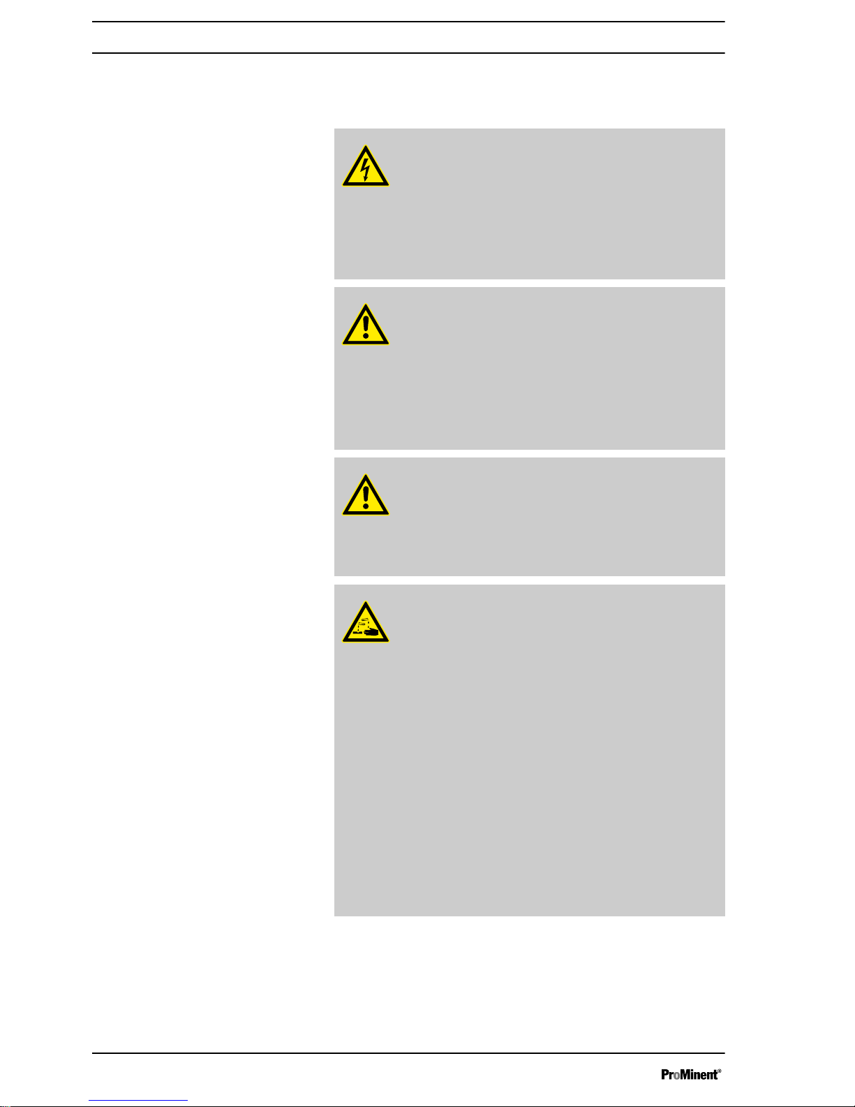
DANGER!
Nature and source of the danger
Consequence: Fatal or very serious injuries.
Measure to be taken to avoid this danger.
Danger!
–
Denotes an immediate threatening danger. If this is
disregarded, it will result in fatal or very serious
injuries.
WARNING!
Nature and source of the danger
Possible consequence: Fatal or very serious injuries.
Measure to be taken to avoid this danger.
Warning!
–
Denotes a possibly hazardous situation. If this is
disregarded, it could result in fatal or very serious
injuries.
CAUTION!
Nature and source of the danger
Possible consequence: Slight or minor injuries. Mate‐
rial damage.
Measure to be taken to avoid this danger.
Caution!
–
Denotes a possibly hazardous situation. If this is
disregarded, it could result in slight or minor inju‐
ries. May also be used as a warning about material
damage.
General non-discriminatory approach
Introduction
Introduction
4
Page 5
NOTICE!
Nature and source of the danger
Damage to the product or its surroundings.
Measure to be taken to avoid this danger.
Note!
–
Denotes a possibly damaging situation. If this is
disregarded, the product or an object in its vicinity
could be damaged.
Type of information
Hints on use and additional information.
Source of the information. Additional measures.
Information!
–
Denotes hints on use and other useful information.
It does not indicate a hazardous or damaging
situation.
1.2 Users' qualifications
WARNING!
Danger of injury with inadequately qualified personnel!
The operator of the plant / device is responsible for
ensuring that the qualifications are fulfilled.
If inadequately qualified personnel work on the unit or
loiter in the hazard zone of the unit, this could result in
dangers that could cause serious injuries and material
damage.
– All work on the unit should therefore only be
conducted by qualified personnel.
–
Unqualified personnel should be kept away from
the hazard zone
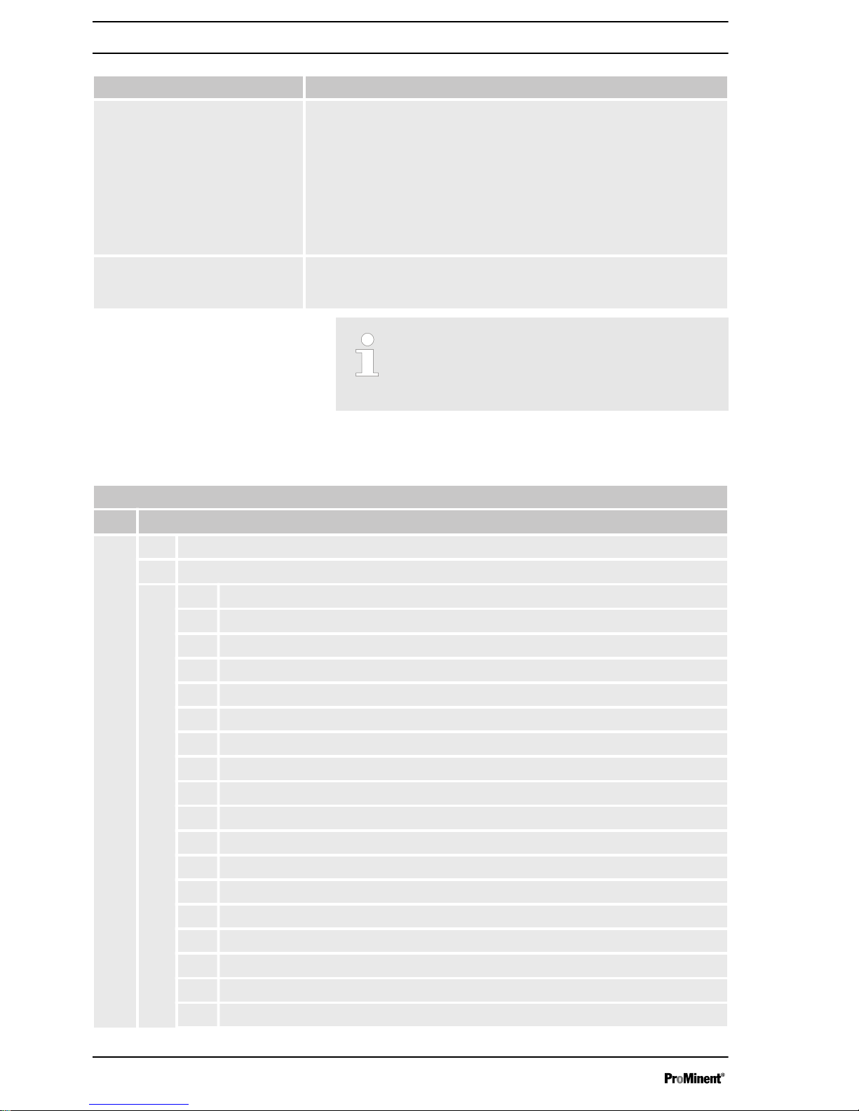
Training Definition
Instructed personnel An instructed person is deemed to be a person who has been
instructed and, if required, trained in the tasks assigned to him/her and
possible dangers that could result from improper behaviour, as well as
having been instructed in the required protective equipment and
protective measures.
Trained user A trained user is a person who fulfils the requirements made of an
instructed person and who has also received additional training
specific to the system from ProMinent or another authorised distribu‐
tion partner.
Trained qualified personnel A qualified employee is deemed to be a person who is able to assess
the tasks assigned to him and recognize possible hazards based on
his/her training, knowledge and experience, as well as knowledge of
pertinent regulations. The assessment of a person's technical training
can also be based on several years of work in the relevant field.
Introduction
5
Page 6
Training Definition
Electrician Electricians are deemed to be people, who are able to complete work
on electrical systems and recognize and avoid possible hazards inde‐
pendently based on his/her technical training and experience, as well
as knowledge of pertinent standards and regulations.
Electricians should be specifically trained for the working environment
in which the are employed and know the relevant standards and regu‐
lations.
Electricians must comply with the provisions of the applicable statutory
directives on accident prevention.
Customer Service department Customer Service department refers to service technicians, who have
received proven training and have been authorised by ProMinent to
work on the system.
Note for the system operator
The pertinent accident prevention regulations, as well
as all other generally acknowledged safety regulations,
must be adhered to!
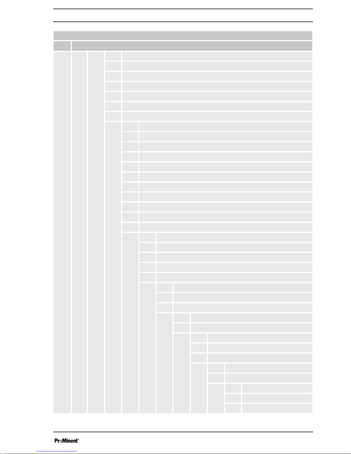
1.3
Identcode DULCO
®
flex DFCa 030
Identcode
DFCa
DULCO
®
flex DFCa 030
Type
030 DFCa 030, 0.433 l/revolution
Drive
000 Pump without drive
Step-down gears / 3 x 230 / 400 VAC
A11 0.25 kW, 18 1/min, 467 l/h, 8 bar
A12 0.37 kW, 28 1/min, 727 l/h, 8 bar
A13 0.55 kW, 38 1/min, 987 l/h, 4 bar
A14 0.55 kW, 55 1/min, 1,428 l/h, 2 bar
A15 0.75 kW, 66 1/min, 1,714 l/h, 2 bar
Manual adjustment gears / 3 x 230 / 400 VAC
A21 0.75 kW, 10-59 1/min, 259-1,532 l/h, 2 bar
Adjustment gears with integrated frequency converter / 1x 230 VAC
A31 0.55 kW, 11.5-40 1/min, 298-1,039 l/h, 4 bar
A32 0.75 kW, 18-64 1/min, 467-1,662 l/h, 2 bar
A33 1.10 kW, 23-80 1/min, 597-2,078 l/h, 1 bar
Adjustment gears (external frequency converter required) / 3 x 230 / 400 VAC
A41 0.37 kW, 2-28 1/min, 51-727 l/h, 8 bar
A42 0.75 kW, 4-57 1/min, 103-1,480 l/h, 2 bar
A43 1.10 kW, 5-80 1/min, 129-2,078 l/h, 1 bar
Introduction
6
Page 7
Identcode
DFCa
DULCO
®
flex DFCa 030
Hose material
0 NR
B NBR
E EPDM
R NR-A
A NBR-A
H Hypalon
Hydraulic connection
A VA BSP 1 1/4"
B VA NPT 1 1/4"
C PP BSP 1 1/4"
D PVDF BSP 1 1/4"
F PVC NPT 1 1/4"
G Tri-Clamp, VA, 1 1/2"
H DIN 11851, VA, NW32
I DIN flange VA DN32
L ANSI flange VA DN32
P ANSI flange PVC DN32
Base plate
0 Base plate, lacquered steel
1 Base plate, stainless steel
2 Portable unit + lacquered steel base plate
3 Portable unit + stainless steel base plate
Leakage sensor
0 without leakage sensor
L with leakage sensor
Rotor
0 Rotor with 2 rollers
Batch control
0 without batch control
C with batch control
Special version
0 Standard
Vacuum system
0 none
V with vacuum system
Introduction
7
Page 8
Identcode
DFCa
DULCO
®
flex DFCa 030
Certification
01 CE mark
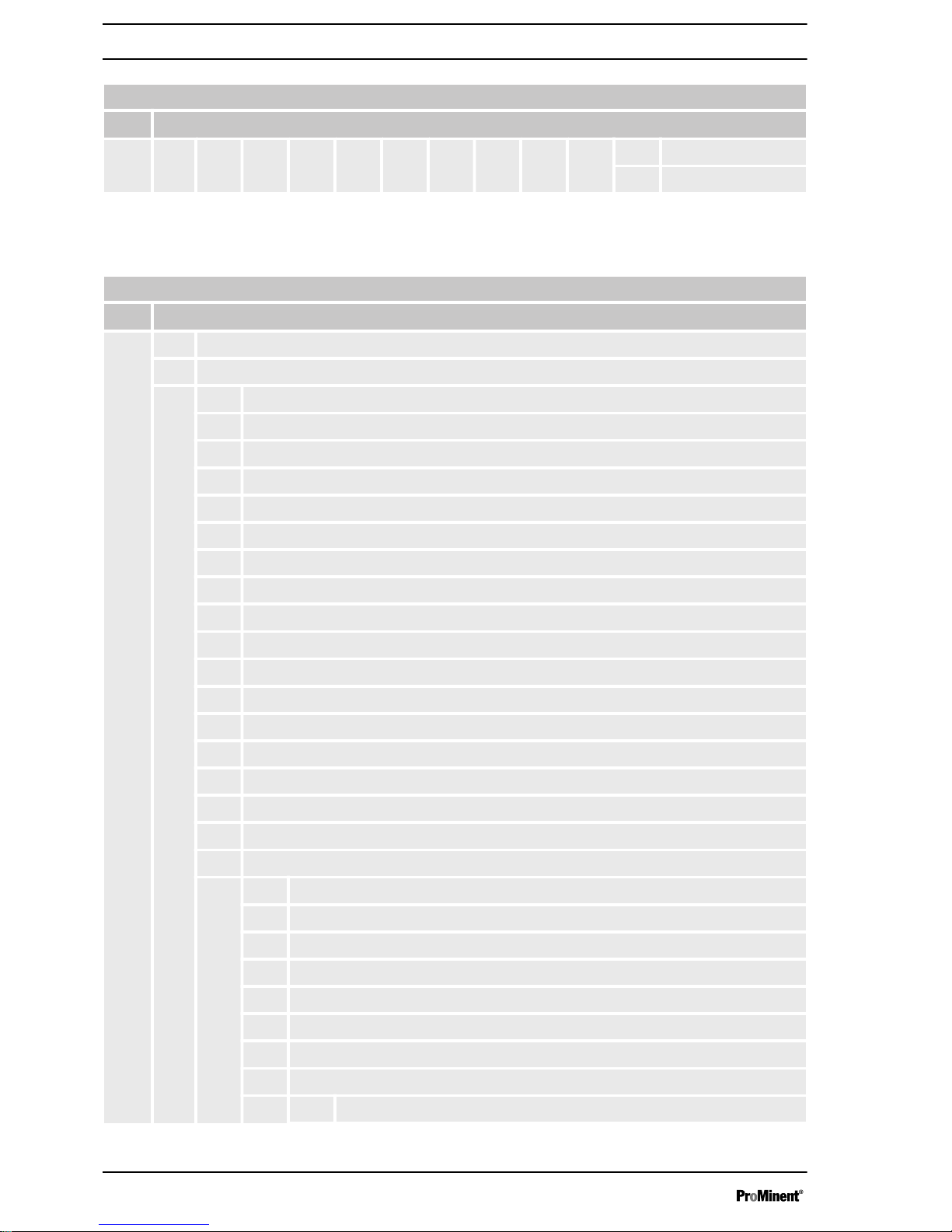
1.4
Identcode DULCO
®
flex DFCa 040
Identcode
DFCa
DULCO
®
flex DFCa 040
Type
040 DFCa 040, 0.91 l/revolution
Drive
000 Pump without drive
Step-down gears / 3 x 230 / 400 VAC
B11 0.55 kW, 18 1/min, 982 l/h, 8 bar
B12 0.55 kW, 29 1/min, 1,583 l/h, 8 bar
B13 0.75 kW, 38 1/min, 2,074 l/h, 4 bar
B14 1.10 kW, 54 1/min, 2,948 l/h, 2 bar
B15 1.50 kW, 66 1/min, 3,603 l/h, 2 bar
Manual adjustment gears / 3 x 230 / 400 VAC
B21 1.10 kW, 16-56 1/min, 873-3,057 l/h, 2 bar
Adjustment gears with integrated frequency converter / 1x 230 VAC
B31 1.10 kW, 12-36 1/min, 655-1,965 l/h, 4 bar
B32 1.50 kW, 15-53 1/min, 819-2,893 l/h, 2 bar
B33 2.20 kW, 22-77 1/min, 1201-4,204 l/h, 1 bar
Adjustment gears (external frequency converter required) / 3 x 230 / 400 VAC
B41 1.10 kW, 2-49 1/min, 109-2,675 l/h, 2 bar
B42 1.50 kW, 4-53 1/min, 218-2,893 l/h, 2 bar
B43 2.20 kW, 7-80 1/min, 382-4,368 l/h, 1 bar
Hose material
0 NR
B NBR
E EPDM
R NR-A
A NBR-A
H Hypalon
N Norprene (max. 2 bar)
Hydraulic connection
Introduction
8
Page 9

Identcode
DFCa
DULCO
®
flex DFCa 040
A VA BSP 1 1/2"
B VA NPT 1 1/2"
C PP BSP 1 1/2"
D PVDF BSP 1 1/2"
G Tri-Clamp, VA, 1 1/2"
H DIN 11851, VA, NW40
I DIN flange VA DN40
L ANSI flange VA DN40
P ANSI flange PVC DN40
Base plate
0 Base plate, lacquered steel
1 Base plate, stainless steel
2 Portable unit + lacquered steel base plate
3 Portable unit + stainless steel base plate
Leakage sensor
0 without leakage sensor
L with leakage sensor
Rotor
0 Rotor with 2 rollers
Batch control
0 without batch control
C with batch control
Special version
0 Standard
Vacuum system
0 none
V with vacuum system
Certification
01 CE mark
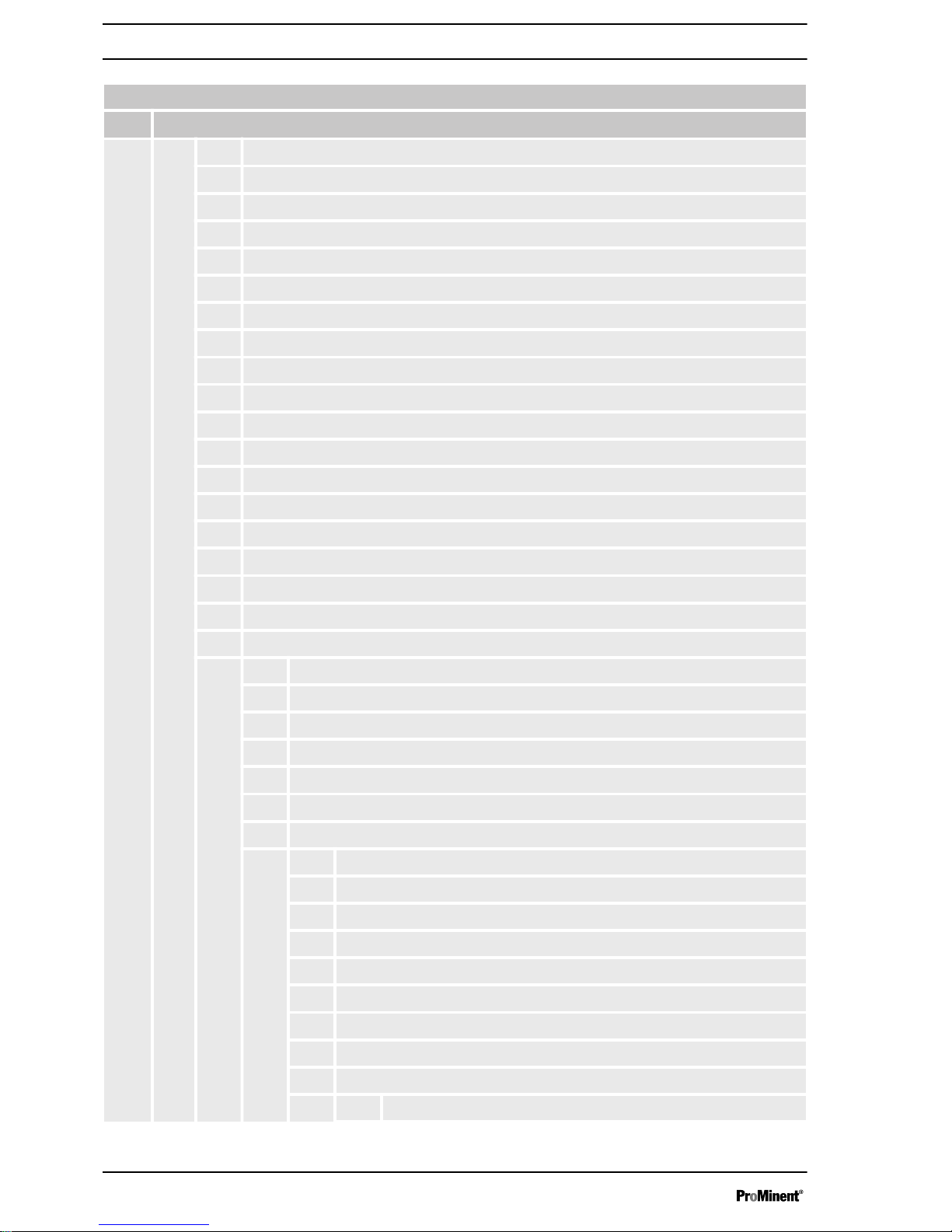
1.5
Identcode DULCO
®
flex DFCa 050
Identcode
DFCa
DULCO
®
flex DFCa 050
Type
050 DFCa 050, 1.46 l/revolution
Introduction
9
Page 10
Identcode
DFCa
DULCO
®
flex DFCa 050
Drive
000 Pump without drive
Step-down gears / 3 x 230 / 400 VAC
C11 0.55 kW, 14.1 1/min, 1,235 l/h, 8 bar
C12 0.75 kW, 21 1/min, 1,839 l/h, 8 bar
C13 1.10 kW, 30 1/min, 2,628 l/h, 4 bar
C14 1.50 kW, 38 1/min, 3,328 l/h, 4 bar
C15 1.50 kW, 48 1/min, 4,204 l/h, 2 bar
C16 2.20 kW, 58 1/min, 5,080 l/h, 2 bar
Manual adjustment gears / 3 x 230 / 400 VAC
C21 1.15 kW, 8.8-44 1/min, 770-3,854 l/h, 4 bar
Adjustment gears with integrated frequency converter / 1x 230 VAC
C31 1.50 kW, 9-32 1/min, 788-2,803 l/h, 4 bar
C32 2.20 kW, 15-54 1/min, 1314-4,730 l/h, 2 bar
C33 3.00 kW, 22-77 1/min, 1927-6,745 l/h, 1 bar
Adjustment gears (external frequency converter required) / 3 x 230 / 400 VAC
C41 1.50 kW, 2-32 1/min, 175-2,803 l/h, 4 bar
C42 2.20 kW, 4-54 1/min, 350-4,730 l/h, 2 bar
C43 3.00 kW, 5.5-77 1/min, 481-6,745 l/h, 1 bar
Hose material
0 NR
B NBR
E EPDM
R NR-A
A NBR-A
H Hypalon
Hydraulic connection
I DIN flange VA DN40
G Tri-Clamp, VA, 2"
H DIN 11851, VA, NW50
J DIN flange PP DN40
K DIN flange VA, Halar coated + PVDF inserts DN40
L ANSI flange VA DN40
M ANSI flange PP DN40
N ANSI flange VA, Halar coated + PVDF inserts DN40
Base plate
Introduction
10
Page 11
Identcode
DFCa
DULCO
®
flex DFCa 050
0 Base plate, lacquered steel
1 Base plate, stainless steel
2 Portable unit + lacquered steel base plate
3 Portable unit + stainless steel base plate
Leakage sensor
0 without leakage sensor
L with leakage sensor
Rotor
0 Rotor with 2 rollers
Batch control
0 without batch control
Special version
0 Standard
Vacuum system
0 none
V with vacuum system
Certification
01 CE mark
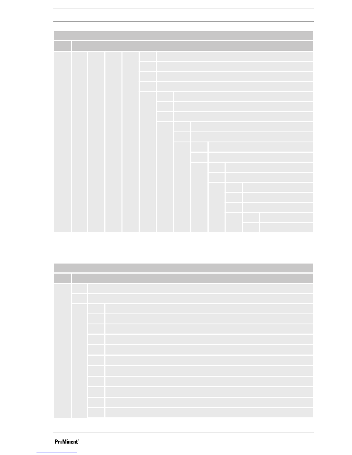
1.6
Identcode DULCO
®
flex DFCa 060
Identcode
DFCa
DULCO
®
flex DFCa 060
Type
060 DFCa 060, 3.12 l/revolution
Drive
000 Pump without drive
Step-down gears / 3 x 230 / 400 VAC
D11
2.20 kW, 18 1/min, 3.3 m3/h, 8 bar
D12
2.20 kW, 21 1/min, 3.9 m3/h, 8 bar
D13
3.00 kW, 27 1/min, 5.0 m3/h, 8 bar
D14
3.00 kW, 33 1/min, 6.1 m3/h, 4 bar
D15
3.00 kW, 42 1/min, 7.8 m3/h, 4 bar
D16
3.00 kW, 47 1/min, 8.7 m3/h, 2 bar
D17
3.00 kW, 57 1/min, 10.6 m3/h, 2 bar
Manual adjustment gears / 3 x 230 / 400 VAC
Introduction
11
Page 12
Identcode
DFCa
DULCO
®
flex DFCa 060
D21
4.0 kW, 8-49 1/min,1.4-9.1 m3/h, 2 bar
Adjustment gears with integrated frequency converter / 1x 230 VAC
D31
3.0 kW, 7-25 1/min, 1.3-4.6 m3/h, 8 bar
D32
4.0 kW, 15-53 1/min, 2.8-9.9 m3/h, 2 bar
Hose material
0 NR
B NBR
E EPDM
R NR-A
A NBR-A
H Hypalon
Hydraulic connection
I DIN Flange, VA, DN50
G Tri-Clamp, VA, 2 1/2"
H DIN 11851, VA, NW50
K DIN flange VA, Halar coated + PVDF inserts, DN50
L ANSI flange VA DN50
M ANSI flange PP, DN50
N ANSI flange VA, Halar coated + PVDF inserts, DN50
Base plate
0 Base plate, lacquered steel
1 Base plate, stainless steel
2 Portable unit + lacquered steel base plate
3 Portable unit + stainless steel base plate
Leakage sensor
0 without leakage sensor
L with leakage sensor
Rotor
0 Rotor with 2 rollers
Batch control
0 without batch control
C with batch control
Special version
0 Standard
Vacuum system
0 none
Introduction
12
Page 13

Identcode
DFCa
DULCO
®
flex DFCa 060
V with vacuum system
Certification
01 CE mark
1.7
Identcode DULCO
®
flex DFCa 070
Identcode
DFCa
DULCO
®
flex DFCa 070
Type
070 DFCa 070, 8.05 l/revolution
Drive
000 Pump without drive
Step-down gears / 3 x 230 / 400 VAC
E11
2.20 kW, 14 1/min, 6.7 m3/h, 8 bar
E12
3.0 kW, 21 1/min, 10.1 m3/h, 8 bar
E13
4.0 kW, 26 1/min, 12.5 m3/h, 4 bar
E14
4.0 kW, 32 1/min, 15.4 m3/h, 4 bar
E15
5.5 kW, 37 1/min, 17.8 m3/h, 4 bar
E16
5.5 kW, 46 1/min, 22.2 m3/h, 2 bar
E17
5.5 kW, 54 1/min, 26.0 m3/h, 2 bar
Adjustment gears with integrated frequency converter / 1x 230 VAC
E31
5.5 kW, 9-23 1/min, 4.3-15.4 m3/h, 4 bar
E32
7.5 kW, 14-47 1/min, 6.7-22.7 m3/h, 2 bar
Hose material
0 NR
B NBR
E EPDM
R NR-A
A NBR-A
H Hypalon
Hydraulic connection
I DIN flange VA, DN65
G Tri-Clamp, VA, 3"
H DIN 11851, VA, NW65
J DIN flange PP, DN65
L ANSI flange VA, DN65
Introduction
13
Page 14
Identcode
DFCa
DULCO
®
flex DFCa 070
M ANSI flange PP, DN65
Q DIN flange VA Halar coated, DN65
R ANSI flange VA Halar coated, DN65
Base plate
0 Base plate, lacquered steel
1 Base plate, stainless steel
2 Portable unit + lacquered steel base plate
3 Portable unit + stainless steel base plate
Leakage sensor
0 without leakage sensor
L with leakage sensor
Rotor
0 Rotor with 2 rollers
Batch control
0 without batch control
Special version
0 Standard
Vacuum system
0 none
V with vacuum system
Certification
01 CE mark
1.8
Identcode DULCO
®
flex DFCa 70D
Identcode
DFCa
DULCO
®
flex DFCa 70D
Type
70D DFCa 70D, 15.83 l/revolution, double head version
Drive
000 Pump without drive
Step-down gears / 3 x 230 / 400 VAC
F11
5.5 kW, 15 1/min, 14.2 m3/h, 4 bar
F12
7.5 kW, 22 1/min, 20.8 m3/h, 2 bar
F13
7.5 kW, 31 1/min, 29.4 m3/h, 2 bar
F14
9.2 kW, 40 1/min, 38.0 m3/h, 2 bar
Introduction
14
Page 15
Identcode
DFCa
DULCO
®
flex DFCa 70D
Hose material
0 NR
B NBR
E EPDM
R NR-A
A NBR-A
Hydraulic connection
I DIN Flange, VA, DN80
G Tri-Clamp, VA, 4"
H DIN 11851, VA, NW80
L ANSI flange, VA DN80
Base plate
0 Base plate, lacquered steel
1 Base plate, stainless steel
Leakage sensor
0 without leakage sensor
L with leakage sensor
Rotor
0 Rotor with 2 rollers
Batch control
0 without batch control
Special version
0 Standard
Vacuum system
0 none
Certification
01 CE mark
Introduction
15
Page 16
2 Safety and responsibility
2.1
General safety information
WARNING!
Live parts
Possible consequence: Fatal or very serious injuries
– Measure: The device must be disconnected from
the power supply before it is opened
–
Isolate damaged, faulty or manipulated devices
from the mains in order to de-energise.
WARNING!
Emergency stop switch
Possible consequence: Fatal or very serious injuries
An emergency stop switch is to be connected for the
entire plant. This should enable the entire plant to be
shut down in the event on an emergency in such a way
that the overall plant can be brought into a safe condi‐
tion.
WARNING!
Unauthorised access
Possible consequence: Fatal or very serious injuries
– Measure: Ensure that there can be no unauthor‐
ised access to the unit
WARNING!
Hazardous media / contamination of persons and
equipment
Possible consequence: Fatal or very serious injuries.
material damage
– Ensure that the pump hoses are resistance against
the media being conveyed
–
Always observe the the safety data sheets for the
media to be conveyed. The system operator must
ensure that these safety data sheets are available
and that they are kept up-to-date
– The safety data sheets for the media being
conveyed are always decisive for initiating counter
measures in the event of leakage to the media
being conveyed
– Observe the general restrictions in relation to
viscosity limits, chemical resistance and density
– Always switch the pump off before exchanging the
pump hose
Safety and responsibility
16
Page 17

WARNING!
Correct and proper use
Possible consequence: Fatal or very serious injuries
– The unit is not intended to convey or regulate
gaseous or solid media
–
Do not exceed the rated pressure, speed or
temperature for the pump
– The unit may only be used in accordance with the
technical data and specifications provided in these
operating instructions and in the operating instruc‐
tions for the individual components
– The system is not designed for use in areas at risk
from explosion
– Only switch the pump on if it has been properly
fastened to the floor
– Only switch the pump on if it the front cover has
been attached.
WARNING!
Operational lifetime of the pump hoses
Possible consequence: Fatal or very serious injuries
The operational lifetime of the pump hoses cannot be
precisely specified. For this reason, the possibility of
fracture and consequential leakage of liquids must be
accounted for. If the hose rupture alarm (optional) is
fitted, then the pump can be stopped and / or an elec‐
trical valve can be actuated.
In addition, you must avoid particles from untight
hoses being introduced into the media being
conveyeed. This can be achieved e.g. by means of
filtration, a hose rupture alarm or other means suitable
for the respective process.
CAUTION!
CIP cleaning
In the event of CIP cleaning, it is necessary to obtain
information from the manufacturer about correct instal‐
lation of the pump (a special installation is required),
as well as regarding the compatibility of the cleaning
agents with the pump hoses of the pump and the other
hydraulic connections.
Cleaning should be undertaken at the recommended
maximum temperature.
CAUTION!
Direction of rotation / flow direction
Possible consequence: Material damage right through
to destruction of the unit
– The pump's direction of rotation in relation to the
desired flow direction must be checked prior to
every start.
Safety and responsibility
17
Page 18

CAUTION!
Environmental influences
Possible consequence: Material damage right through
to destruction of the unit
– The device is not suitable for outdoor operation
–
Take suitable measures to protect the device from
environmental influences such as:
– UV rays
– Moisture
– Frost, etc.
Safety and responsibility
18
Page 19

3 Functional description
The package contents supplied with the DULCOflex® DFCa is
selectable via the identcode.
The DULCOflex® DFCa is a displacement pump. The feed chem‐
ical is transported by the rotor squeezing the hose in the direction
of flow. No valves are needed for this. This ensures gentle
handling of the metered media.
The DULCOflex® DFCa has been designed for safe and uncompli‐
cated operation, as well as straightforward maintenance.
The DULCOflex® DFCa can be used for many different media.
However, this pump type is often the optimal solution for abrasive,
shear-sensitive and viscose media.
Typical areas of use include processes where only a low discharge
pressure is required (max. 8 bar).
3.1
Construction
Main modules:
n Drive Unit
n Housing
n Base frame
The pump housing is closed off with a screwed front cover in order
to avoid the risk of injury.
The motor serves to drive the rotor. Two rollers at the ends of the
rotor serve to press the pump hose against the pump housing.
The rotary movement of the rotors alternately press and relax the
rollers in relation to the pump hose. This serves to suck the media
in and convey it into the metering line.
Brief functional description
Functional description
19
Page 20

3.2 Overview of the Device
P_DX_0017_SW
Fig. 1: Diagram of functional principle
1 Housing
2 Rotor
3 Rollers
4 Hose
Functional description
20
Page 21

4 Transport, storage, assembly and Installation
n User qualification, transport and storage: instructed persons,
see
Ä Chapter 1.2 “Users' qualifications” on page 5
n User qualification, assembly: trained qualified personnel, see
Ä Chapter 1.2 “Users' qualifications” on page 5
n User qualification, electrical installation: Qualified electrician,
see
Ä Chapter 1.2 “Users' qualifications” on page 5
WARNING!
Safety data sheet
Possible consequence: Fatal or very serious injuries
Always observe the corresponding data sheets for the
media when carrying out any tasks which involve
contact with the media that is to be conveyed.
4.1 Transport
Transport
n The pump is protected by means of cardboard packaging
n The packaging materials can be recycled
n For environmental conditions for storage and transportation
see
4.2 Storage
Storage
n The pump hose should be removed from the housing during
the duration of storage
n For storage durations longer than 60 days, the coupling
surfaces (terminals, reducing adaptors, motors) are to be
protected with suitable antioxidant agents
n For environmental conditions for storage and transportation
see
4.3 Assembly
CAUTION!
Possible consequence: Slight or minor injuries, mate‐
rial damage.
Carry out the assembly work before the electrical
installation is undertaken!
Observe the permissible environmental conditions!
Transport, storage, assembly and Installation
21
Page 22

4.3.1 Ambient conditions
NOTICE!
Ambient conditions
Possible consequence: Property damage and
increased wear and tear
Assembly is to be carried out in the following order. If
the must has to be installed outdoors, then it is to be
equipped with protection against sunlight and weather
influences.
When positioning the pump, ensure that sufficient
room for access is provided for all types of mainte‐
nance work.
There are limit values for temperature and pressure, depending on
the type of hose selected. These limit values are described in the
following section:
Limit values for hose temperature and pressure
Material
Hose
min. temp. (°C)
Feed chemical
max. temp. (°C)
Feed chemical
min. temp. (°C)
Environment
max. pressure (bar)
NR -20 80 -40 8
NBR -10 80 -40 8
EPDM -10 80 -40 8
NR-A -10 80 -40 8
NBR-A -10 80 -40 8
NORPREN -40 120 -40 2
Also observe the general safety information, see
Ä Chapter 2.1 “General safety information” on page 16
4.3.2 Alignment of the suction side
The pump is to be positioned as near as possible to the liquid
container, so that the suction side is kept as short and straight as
possible.
The suction line must be absolutely airtight and made of a suitable
material, so that it is not squeezed together under vacuum.
The diameter must correspond to the rated diameter of the pump
hose. A larger diameter is recommended in the event of viscose
liquids.
The pump is self-priming and does not require an admission valve.
The pump is reversible and the suction connection can therefore
comprise of one of two options. Normally the option is selected
which is best suited to the physical conditions of the installation.
It is recommended to use a flexible transition between two fixed
pipes and the hydraulic connection of the pump, in order to avoid
the transmission of vibrations.
Transport, storage, assembly and Installation
22
Page 23

4.3.3 Alignment of the discharge side
The discharge line is to be kept as straight and short as possible,
in order to avoid performance reduction.
The diameter must correspond to the rated diameter of the pump
hose. A larger diameter is recommended in the event of viscose
liquids.
It is recommended to use a flexible transition between two fixed
pipes and the hydraulic connection of the pump, in order to avoid
the transmission of vibrations.
4.3.4
Adjusting the roller pressure
The peristaltic pump is equipped with spacer plates (6), in order to
adjust the precise pressure distance to the roller (9) (dependent on
speed and operating pressure).
P_DX_0013_SW
Fig. 2: Space plates / roller
6 Spacer plates
9 Roller
Transport, storage, assembly and Installation
23
Page 24

1
23
4
P_DX_0021_SW
Fig. 3: Squeezing the hose
1 Hose in normal shape
2 Excessive squeezing (increased wear and tear
to pump and hose)
3 Perfect squeezing
4 Insufficient squeezing (backflowing media in the
cavity will destroy the hose within a short period
of time)
The spacer plates are fitted in the factory. You can adapt the
number of spacer plates to the actual operating conditions
according to the following table.
DFCa 030 / Number of spacer plates of 0.5 mm thickness (except
Norpren):
1/min 0-19 20-39 40-59 60-79 80-99
bar
0.5 2 2 1 1 1
2.0 2 2 2 2 2
4.0 * 3 2 2 2 2
6.0 3 3 3 2 -
8.0 4 3 3 - -
* Supplied state
DFCa 040 / Number of spacer plates of 1.0 mm thickness (except
Norpren):
1/min 0-19 20-39 40-59 60-79 80-99
bar
0.5 4 4 4 4 3
2.0 5 4 4 4 4
4.0 * 5 5 5 4 4
6.0 6 5 5 - -
8.0 6 6 - - -
* Supplied state
Transport, storage, assembly and Installation
24
Page 25

DFCa 040 / Number of spacer plates of 1.0 mm thickness (except
Norpren):
1/min 0-19 20-39 40-59 60-79 80-99
bar
0.5 14 14 14 14 14
2.0* 14 14 14 14 14
* Supplied state
DFCa 050 / Number of spacer plates of 1.0 mm thickness:
1/min 0-19 20-39 40-59 60-79 80-99
bar
0.5 1 1 1 0 0
2.0 2 1 1 1 1
4.0 * 2 2 2 2 2
6.0 3 3 3 3 -
8.0 4 3 - - -
* Supplied state
DFCa 060 / Number of spacer plates of 1.0 mm thickness:
1/min 0-19 20-39 40-59 60-79 80-99
bar
0.5 7 6 6 6 6
2.0 7 7 7 7 6
4.0 * 7 7 7 7 7
6.0 8 7 7 7 7
8.0 8 8 8 7 -
* Supplied state
DFCa 070 / Number of spacer plates of 1.0 mm thickness:
1/min 0-19 20-39 40-59 60-79 80-99
bar
0.5 1 1 0 0 0
2.0 1 1 1 0 0
4.0 * 2 2 2 1 1
6.0 3 3 2 - -
8.0 4 3 3 - -
* Supplied state
Transport, storage, assembly and Installation
25
Page 26

4.3.5 Performance curves
NOTICE!
Maximum pressure under continuous operation
The dotted line indicates the limit for maximum pres‐
sure under continuous operation
A0369
Fig. 4: DFCa 030
A0370
1/min
l /h
10 20 30 40 50 60 70 80
4400
3960
3520
3080
2640
2200
1760
1320
880
440
0
8 bar 4 bar 2 bar
Fig. 5: DFCa 040
Transport, storage, assembly and Installation
26
Page 27

A0371
Fig. 6: DFCa 050
A0372
Fig. 7: DFCa 060
Transport, storage, assembly and Installation
27
Page 28

A0373
1/min
m/h
30
27
24
21
18
15
12
9
6
3
0
10 2 0 30 40 50 60 70
3
Fig. 8: DFCa 070
Transport, storage, assembly and Installation
28
Page 29

5 Commissioning
n User qualification, commissioning: trained user, see
Ä Chapter
1.2 “Users' qualifications” on page 5
5.1 Testing prior to commissioning the pump
The following tests are to be carried out:
n Ensure that the pump has not been damaged during transpor‐
tation or storage. Immediately report any damage to the
supplier
n Check that the mains voltage is suitable for the motor
n Ensure that the hose is suitable for the fluid to be conveyed
and that it is not damaged
n Make sure that the temperature of the liquid does not exceed
the recommended temperature range
n Only switch the pump on if it the front cover has been properly
attached
n Check that the rollers are correctly fitted and fastened
n Check that the hose and rollers are sufficiently lubricated
n Check that the thermal overload protection (not included in the
delivery scope) corresponds to the value specified on the
motor type plate
n Check whether the direction of rotation is correctly adjusted
n Check that the optional electrical components are connected
and are working properly
n Install a manometer in the pressure line if the back-pressure
value is unknown
n Check the operating instructions in order to ensure that the
flow values, pressures and power consumption of the motor do
not exceed the rated values
n Install a pressure relief valve in the pressure line in order to
protect the pump in the event that a valve is unintentionally
closed off or the line is blocked in another way.
Commissioning
29
Page 30

6 Operation of the peristaltic pump
n User qualification, operation: instructed persons, see
Ä Chapter 1.2 “Users' qualifications” on page 5
The peristaltic pump is to be fully integrated into the customer's
designated plant and is then controlled by this plant. It is not
possible to operate the pump directly.
Operation of the peristaltic pump
30
Page 31

7 Maintenance, repair, malfunctions, disposal and spare parts
n User qualification, maintenance and disposal: instructed
persons, see
Ä Chapter 1.2 “Users' qualifications” on page 5
n User qualification, repair and malfunctions: trained user, see
Ä Chapter 1.2 “Users' qualifications” on page 5
7.1 Maintenance
CAUTION!
Disconnect the pump from the mains
Possible consequence: Personal injury
You may only carry out work on the pump after it has
previously been switched off and disconnected from
the mains.
Lubrication
n Check that the rollers and the hose are sufficiently lubricated
–
Check every 200 operating hours
n Check whether the oil level is correct for the step-down gears
– Exchange the oil at regular intervals in accordance with the
step-down gear maintenance manual.
7.2 Exchanging the pump hoses
1. Close off all valves, in order to prevent leakage of the feed
chemical
2. Dismantle the pump hoses from both discharge and suction
sides
3. Remove the front cover
4. Remove a roller incl. the spacer plate (the roller that is not
touching the pump hose)
5. Turn the rotor with the help of the motor so that the remaining
roller is not pressing against the pump hose
6. Remove the pressure flange from the pump housing
7. Remove the pump hose to be exchanged
8. Dismantle the hydraulic connections from both pump hose
ends
1. Clean the interior surfaces of the pump housing
2. Lubricate the internal surfaces of the pump housing at the
contact surfaces to the pump hose
3. Check the rollers. Ensure that the roller surfaces are not
damaged
4. Attach the hydraulic connections at both hose ends with the
help of the pressure flange
5. Lay the pump hose into the pump housing
6. Lubricate the pump hose and the rollers
7. Fasten the pressure flange to the pump casing
Exchanging the pump hoses dismantling
Exchanging the pump hoses - installa‐
tion
Maintenance, repair, malfunctions, disposal and spare parts
31
Page 32

8. Turn the rotor with the help of the motor so that the remaining
roller presses against the pump hose
9. Re-attach the second roller with spacer plates back onto the
rotor
10. Attach the front cover to the pump housing
11. Mount the pump hoses from both discharge and suction
sides
12. Open all of the valves
7.3
Troubleshooting
Problem Possible cause Solution
Increased pump temperature Pump hose has no lubricant Lubricate pump hose
Increased product temperature Reduce product temperature
Insufficient or poor suction condi‐
tions
Check suction line for blockages
Pump speed too high Reduce pump speed
Reduced flow or pressure Valves on discharge and or
suction side completely or partially
closed
Open valves
Pump hose insufficiently
compressed
Check roller fastening
Pump hose rupture (the product
leaks out into the housing)
Exchange pump hose
Partial blockage of the suction line Clean pipe
Insufficient product quantity in
storage container
Fill storage container or exchange
pump
Insufficient diameter on the
suction side
Increase the diameter on the
suctions side, as far as possible
Suction line too long Shorten the suction line, as far as
possible
High viscosity of medium Reduce viscosity, as far as
possible
Air introduction in the suction
connections
Check connections and accesso‐
ries for air tightness
Vibrations on pumps and pipelines The pipes are not correctly
fastened
Fasten pipes correctly (e.g. wall
brackets)
Pump speed too high Reduce pump speed
Insufficient nominal width of the
pipes
Increase nominal width
Pump base plate loose Fasten base plate
Pulsation dampers insufficient or
missing
Install pulsation dampers on
suction and / or discharge side.
Short operational lifetime of the
hoses
Chemical exposure Check the compatibility of the
hose with the liquid being
conveyed, the cleaning fluid and
the lubricant
Maintenance, repair, malfunctions, disposal and spare parts
32
Page 33

Problem Possible cause Solution
High pump speed Reduce pump speed
High conveying temperature Reduce product temperature
High operating pressure Reduce operating pressure
Pump cavitations Check the suction conditions
Pump hose pulled into the pump
housing
High inlet pressure (> 3 bar) Reduce inlet pressure
Pump hose filled with deposits Clean or replace the pump hose
Holder (pressure flange) insuffi‐
ciently tightened
Re-tighten holder (pressure
flange)
The pump does not start up Insufficient motor performance Check motor and replace if neces‐
sary
Insufficient output from frequency
converter
The frequency converter must
match the motor
Check voltage. Start occurs at
minimum 10 Hz
Blockage in the pump Check if the suction or discharge
side is blocked. Rectify blockage
Maintenance, repair, malfunctions, disposal and spare parts
33
Page 34

7.4 Disposal of Used Parts
WARNING!
Danger due to feed chemicals
Possible consequence: Fatal or serious injuries
In the event that damage to the pump hose causes the
pump to be contaminated with feed chemicals, then it
is to be decontaminated with suitable agents (refer to
the feed chemical safety data sheets).
NOTICE!
If no Declaration of Decontamination is affixed to the
delivery, acceptance of the devices will be refused.
(also available as download from: www.promi‐
nent.com)
A signed "Declaration of Decontamination" is required
by law and in order to protect our staff, before you
order can be processed.
Please ensure that this is attached to the outside of the
package. Otherwise we are unable to accept your
delivery.
NOTICE!
Regulations governing disposal of used parts
– Note the current national regulations and legal
standards which apply in your country
The pump hose is to be removed and disposed of on-site before
sending the pump to ProMinent Dosiertechnik GmbH, Heidelberg /
Germany.
ProMinent Dosiertechnik, Heidelberg/Germany is prepared to take
back clean used parts.
7.5 Spare parts
Maintenance, repair, malfunctions, disposal and spare parts
34
Page 35

20
10
11
7
8
5
6
9
24
15
27
4
16
12
13
14
28
1
3
22
26
2
18
25
22
17
19
21
A0364
Fig. 9: Spare parts exploded view DFCa 30
DFCa 030
refer to Fig. 9
Pos. Description Quantity Reference Part number
1 Pump housing 1 107.00.01
2 Ball bearing housing 1 107.00.03
3 Rotor shaft 1 107.00.04
4 Rotor 1 107.00.05
5 Roller holder 2 107.00.06
6 Spacer plate 107.00.07
7 Headless screw 2 107.00.08
8 Roller shaft 2 107.00.09
9 Roller 2 107.00.11
10 Metal cover 1 107.00.13
11 Front cover (polycarbonate) 1 107.00.14
12 Pressure flange, standard 2 107.00.15
13 Press ring 2 100.00.05
14 Connection VA 1 1/4" BSP 2 107.00.17
Connection VA 1 1/4" NPT 2 107.00.34
Connection DIN 11851 NW32 2 107.00.35
Connection TRI-CLAMP 2 107.00.36
Maintenance, repair, malfunctions, disposal and spare parts
35
Page 36

DFCa 030
refer to Fig. 9
Pos. Description Quantity Reference Part number
Connection DIN DN32 VA 2 107.00.37
Connection ANSI DN32 VA 2 107.00.38
Connection PP 1 1/4" BSP 2 107.00.39
15 Pump hose NR 1 1037183
Pump hose NR-A 1 1037186
Pump hose NBR 1 1037184
Pump hose NBR-A 1 1037187
Pump hose EPDM 1 1037185
Pump hose HYPALON 1 1037188
16 Cap 1 110.00.23
17 Base plate left 1 100.01.24
Base plate left, stainless steel 1 100.01.34
18 Base plate right 1 100.01.25
Base plate right, stainless steel 1 100.01.35
19 Base plate centre 2 100.01.26
Base plate centre, stainless steel 2 100.01.36
20 Stay bolts 2 102.00.14
21 Drive 1
22 Ball bearings 2 100.01.28
24 Ball bearings 4 107.00.30
25 Rotor washer 1 100.01.31
26 Seal 1 100.01.32
27 Seal 4 100.01.33
28 Lifting lug 1 106.00.40
29 Drain plug FMP 3 107.00.41
Maintenance, repair, malfunctions, disposal and spare parts
36
Page 37

20
10
11
7
8
5
6
9
24
15
27
4
16
12
13
14
28
1
3
22
26
2
18
25
23
17
19
21
A0365
Fig. 10: Spare parts exploded view DFCa 40
DFCa 040
refer to Fig. 10
Pos. Description Quantity Reference Part number
1 Pump housing 1 106.00.01
2 Ball bearing housing 1 106.00.03
3 Rotor shaft 1 106.00.04
4 Rotor 1 106.00.05
5 Roller holder 2 106.00.06
6 Spacer plate 1 mm 106.00.07
Spacer plate 4 mm 106.00.49
7 Headless screw 2 106.00.08
8 Roller shaft 2 106.00.09
9 Roller 2 106.00.11
10 Metal cover 1 106.00.13
Metal cover (vacuum version) 106.00.43
11 Front cover (polycarbonate) 1 106.00.14
12 Pressure flange, standard 2 106.00.15
13 Press ring 2 104.00.05
14 Connection VA 1 1/2" BSP 2 106.00.17
Connection VA 1 1/2" NPT 2 106.00.34
Maintenance, repair, malfunctions, disposal and spare parts
37
Page 38

DFCa 040
refer to Fig. 10
Pos. Description Quantity Reference Part number
Connection DIN 11851 NW40 2 106.00.35
Connection TRI-CLAMP 2 106.00.36
Connection DIN DN40 VA 2 106.00.37
Connection ANSI DN40 VA 2 106.00.38
Connection PP 1 1/2" BSP 2 106.00.39
Connection PVDF 1 1/2" BSP 2 106.00.41
Connection PP 1 1/2" NPT 2 106.00.47
Connection SMS-38 2 106.00.42
15 Pump hose NR 1 1037192
Pump hose NR-A 1 1037195
Pump hose NBR 1 1037193
Pump hose NBR-A 1 1037196
Pump hose EPDM 1 1037194
Pump hose HYPALON 1 1037197
Pump hose NORPRENE 1037198
16 Cap 1 110.00.23
17 Base plate left 1 106.00.24
Base plate left, stainless steel 1 106.00.44
18 Base plate right 1 106.00.25
Base plate right, stainless steel 1 106.00.45
19 Base plate centre 2 106.00.26
Base plate centre, stainless steel 2 106.00.46
20 Stay bolts 2 106.00.27
21 Drive 1
22 Ball bearings 1 106.00.28
23 Ball bearings 1 106.00.29
24 Ball bearings 4 106.00.30
25 Rotor washer 1 106.00.31
26 Seal 1 106.00.32
27 Seal 4 106.00.33
28 Lifting lug 1 106.00.40
29 Drain plug FMP 3 107.00.41
Maintenance, repair, malfunctions, disposal and spare parts
38
Page 39

20
10
11
7
8
5
6
9
24
15
27
4
16
12
13
14
28
1
3
22
26
2
18
25
23
17
19
21
A0366
Fig. 11: Spare parts exploded view DFCa 050
DFCa 050
refer to Fig. 11
Pos. Description Quantity Reference Part number
1 Pump housing 1 108.00.01
2 Ball bearing housing 1 108.00.02
3 Rotor shaft 1 108.00.03
4 Rotor 1 108.00.04
5 Roller holder 2 108.00.05
6 Spacer plate 108.00.06
7 Headless screw 2 108.00.07
8 Roller shaft 2 108.00.08
9 Roller 2 108.00.09
10 Metal cover 1 108.00.10
11 Front cover (polycarbonate) 1 108.00.39
12 Pressure flange, standard 2 108.00.11
13 Press ring 2 108.00.12
14 Connection VA DN50 2 108.00.13
Connection ANSI DN50 VA 2 108.00.14
Connection PP DN50 2 108.00.16
Maintenance, repair, malfunctions, disposal and spare parts
39
Page 40

DFCa 050
refer to Fig. 11
Pos. Description Quantity Reference Part number
Connection ANSI PP DN50 2 108.00.17
Connection PVDF DN50 2 108.00.18
Connection ANSI PVDF DN50 2 108.00.19
Connection DIN 11851 NW50 2 108.00.15
Connection TRI-CLAMP 2
15 Pump hose NR 1 1037199
Pump hose NR-A 1 1037203
Pump hose NBR 1 1037201
Pump hose NBR-A 1 1037204
Pump hose EPDM 1 1037202
Pump hose HYPALON 1 1037205
16 Cap 1
17 Base plate left 1 108.00.26
Base plate left, stainless steel 1 108.00.36
18 Base plate right 1 108.00.27
Base plate right, stainless steel 1 108.00.37
19 Base plate centre 2 108.00.28
Base plate centre, stainless steel 2 108.00.38
20 Stay bolts 2
21 Drive 1
22 Ball bearings 1 108.00.29
23 Ball bearings 1 108.00.30
24 Ball bearings 4 108.00.31
25 Rotor washer 1 108.00.32
26 Seal 1 108.00.33
27 Seal 4 108.00.34
28 Lifting lug 1
29 Drain plug FMP-50 3
30 O-ring front cover 1 108.00.35
31 Adapter rotor 2 108.00.44
Maintenance, repair, malfunctions, disposal and spare parts
40
Page 41

20
3
21 22
25
2729
1
35
15 16 1732
18
26 3029
4
12 13 14195
11
286
7 8
9
10
31
A0367
Fig. 12: Spare parts exploded view DFCa 060
DFCa 060
refer to Fig. 12
Pos. Description Quantity Reference Part number
1 Pump housing 1 110.00.01
3 Ball bearing housing 1 110.00.03
4 Rotor shaft 1 110.00.04
5 Rotor 1 110.00.05
6 Roller holder 2 110.00.06
7 Spacer plate 1 mm 110.00.07
Spacer plate 7 mm 110.00.55
Spacer plate 5mm 110.00.56
8 Headless screw 2 110.00.08
9 Roller shaft 2 110.00.09
10 Spacer 4 110.00.10
11 Roller 2 110.00.11
12 Adapter rotor 2 110.00.12
13 O-ring front cover 1 110.00.13
14 Front cover 1 110.00.14
15 Pressure flange, standard 2 110.00.15
Maintenance, repair, malfunctions, disposal and spare parts
41
Page 42

DFCa 060
refer to Fig. 12
Pos. Description Quantity Reference Part number
16 Insert VA 2 110.00.16
Insert PP 2 110.00.46
Insert PVDF 2 110.00.47
17 Connection DIN 2 110.00.17
Connection ANSI 2 110.00.41
Connection TRI-CLAMP 2 110.00.42
Connection DIN 11851 2 110.00.43
Connection DIN (HALAR) 2 110.00.44
Connection ANSI (HALAR) 2 110.00.45
18 Pump hose NR 1 1037206
Pump hose NR-A 1 1037210
Pump hose NBR 1 1037208
Pump hose NBR-A 1 1037211
Pump hose EPDM 1 1037209
Pump hose HYPALON 1 1037212
19 Cap 1 110.00.23
20 Base plate left 1 110.00.37
Base plate left, stainless steel 1 110.00.48
21 Base plate right 1 110.00.38
Base plate right, stainless steel 1 110.00.49
22 Base plate centre, 110 mm 2 110.00.39
Base plate centre, 110 mm, stainless
steel
2 110.00.50
23 Base plate centre, 60 mm 2 110.00.40
Base plate centre, 60 mm, stainless steel 2 110.00.51
24 Stay bolts 2 106.00.27
25 Drive 1
26 Ball bearings 1 110.00.26
27 Ball bearings 1 110.00.27
28 Ball bearings 4 110.00.28
29 Flexible o-ring for shaft 1 110.00.29
30 Seal 1 110.00.30
31 Seal 4 110.00.31
32 O-ring 1 110.00.32
34 O-ring 2 110.00.33
35 Lifting lug 1 110.00.34
Maintenance, repair, malfunctions, disposal and spare parts
42
Page 43

DFCa 060
refer to Fig. 12
Pos. Description Quantity Reference Part number
36 Nut 2 110.00.35
37 Nut 2 110.00.36
38 Drain plug FMP 3 107.00.41
39 Test valve 1 110.00.53
2
3
22
16
25
23
26
13
12
14
18
21
19
17
28
27
24
30
9
8
7
1
15
6
5
31
4
10
33
34
A0368
Fig. 13: Spare parts exploded view DFCa 070
DFCa 070
refer to Fig. 13
Pos. Description Quantity Reference Part number
1 Pump housing 1 112.00.01
2 Ball bearing housing 1 111.00.03
3 Rotor shaft 1 111.00.04
4 Rotor 1 112.00.05
5 Roller holder 2 112.00.03
6 Spacer plate 112.00.04
7 Headless screw 2 112.00.05
8 Roller shaft 2 112.00.06
9 Roller 2 112.00.07
10 Front cover 1 112.00.08
Maintenance, repair, malfunctions, disposal and spare parts
43
Page 44

DFCa 070
refer to Fig. 13
Pos. Description Quantity Reference Part number
12 Pressure flange, standard 2 112.00.09
13 Press ring 2 112.00.10
14 Connection DIN VA 2 112.00.11
Connection ANSI VA 2 112.00.12
Connection DIN 11851 NW65 2 112.00.13
Connection DIN PP 2 112.00.14
Connection ANSI PP 2 112.00.15
Connection DIN PVDF 2 112.00.16
Connection ANSI PVDF 2 112.00.17
Connection TRI-CLAMP 2 112.00.43
15 Pump hose NR 1 1037213
Pump hose NR-A 1 1037216
Pump hose NBR 1 1037214
Pump hose NBR-A 1 1037217
Pump hose EPDM 1 1037215
Pump hose HYPALON 1 1037218
16 Cap 1 111.00.08
17 Base plate left 1 112.00.24
Base plate left, stainless steel 1 112.00.36
18 Base plate right 1 112.00.25
Base plate right, stainless steel 1 112.00.37
19 Base plate centre 2 112.00.26
Base plate centre, stainless steel 2 112.00.38
20 Stay bolts 2 112.00.44
21 Drive 1
22 Ball bearings 1 111.00.28
23 Ball bearings 1 111.00.29
24 Ball bearings 4 112.00.27
25 Rotor washer 1 111.00.30
26 Seal 1 111.00.31
27 Seal 4 112.00.28
28 Lifting lug 1 112.00.29
29 Drain plug FMP-70 3 112.00.30
30 Spacer 1 112.00.31
31 Adapter rotor 2 112.00.32
32 Inspection window (fixed version) 2 112.00.33
Maintenance, repair, malfunctions, disposal and spare parts
44
Page 45

DFCa 070
refer to Fig. 13
Pos. Description Quantity Reference Part number
33 Inspection window (moveable version) 3 112.00.34
34 O-ring front cover 1 112.00.35
Lubricant
Pos. Description Quantity Reference Part number
1 0.5 kg silicone grease 1 1037255
2 1.0 kg silicone grease 1 1037256
Maintenance, repair, malfunctions, disposal and spare parts
45
Page 46

8 DFCa technical data
Type
DFCa
Feed rate
in l/U
P max.
in bar
Flow rate
at max.
pressure
in l/h
Rollers/
shoes
Shoes
Hose
interior
⌀ in mm
Solids
max.
⌀ in mm
Weight
without
drive
in kg
Connecto
r
030 0.43 8 700 Rollers 28 7.0 62 1 1/4"
040 0.81 8 1550 Rollers 35 8.8 89 1 1/2"
050 1.46 8 2400 Rollers 40 10.0 140 DN 40
060 3.12 8 6000 Rollers 55 13.8 235 DN 50
070 8.05 8 12000 Rollers 65 16.3 440 DN 65
70D 15.83 4 25000 Rollers 65 16.3 850 DN 80
DFCa technical data
46
Page 47

8.1 Dimensions DFCa 030
Fig. 14: Dimensions DFCa 030
A 127.5 mm
B *
C *
D 60 mm
E 425 mm
F 305 mm
G 471 mm
H 305 mm
I 160 mm
J 100 mm
K 262 mm
L 75 mm
M 1 1/4"
* Dependent on selected drive
DFCa technical data
47
Page 48

8.2 Dimensions DFCa 040
A0376
Fig. 15: Dimensions DFCa 040
A 135 mm
B *
C *
D 70 mm
E 613 mm
F 345 mm
G 552 mm
H 385 mm
I 170 mm
J 130 mm
K 330 mm
L 95 mm
M 1 1/2"
* Dependent on selected drive
DFCa technical data
48
Page 49

8.3 Dimensions DFCa 050
A0377
Fig. 16: Dimensions DFCa 050
A 151 mm
B *
C *
D 79 mm
E 645 mm
F 415 mm
G 633 mm
H 453 mm
I 200 mm
J 159 mm
K 412 mm
L 115 mm
* Dependent on selected drive
DFCa technical data
49
Page 50

8.4 Dimensions DFCa 060
A0378
Fig. 17: Dimensions DFCa 060
A 215 mm
B *
C *
D 111 mm
E 805 mm
F 740 mm
G 735 mm
H 500 mm
I 25 mm
J 210 mm
K 510 mm
L 25 mm
* Dependent on selected drive
DFCa technical data
50
Page 51

8.5 Dimensions DFCa 070
A0379
Fig. 18: Dimensions DFCa 070
A 215 mm
B *
C *
D 250 mm
E 1124 mm
F 1065 mm
G 1100 mm
H 790 mm
I 40 mm
J 240 mm
K 784 mm
L 40 mm
* Dependent on selected drive
DFCa technical data
51
Page 52

9 DFCa technical appendices
9.1
Declaration of Conformity
Fig. 19: EC Declaration of Conformity
DFCa technical appendices
52
Page 53

10 Index
B
Backflowing media............................................... 24
C
Correct and proper use........................................ 17
Counter measures
................................................ 17
D
Displacement pump............................................. 19
Disposal............................................................... 34
E
Emergency stop switch........................................ 16
F
Functional principle.............................................. 20
G
General non-discriminatory approach.................... 4
L
Live parts.............................................................. 16
N
Non-discriminatory approach................................. 4
R
Rollers.................................................................. 24
S
Safety data sheet................................................. 17
Safety information................................................ 16
Safety Information.................................................. 4
Spacer plates....................................................... 24
Squeezing the hose............................................. 24
U
Unauthorised access............................................ 16
Users' qualifications............................................... 5
Index
53
 Loading...