

Page 1
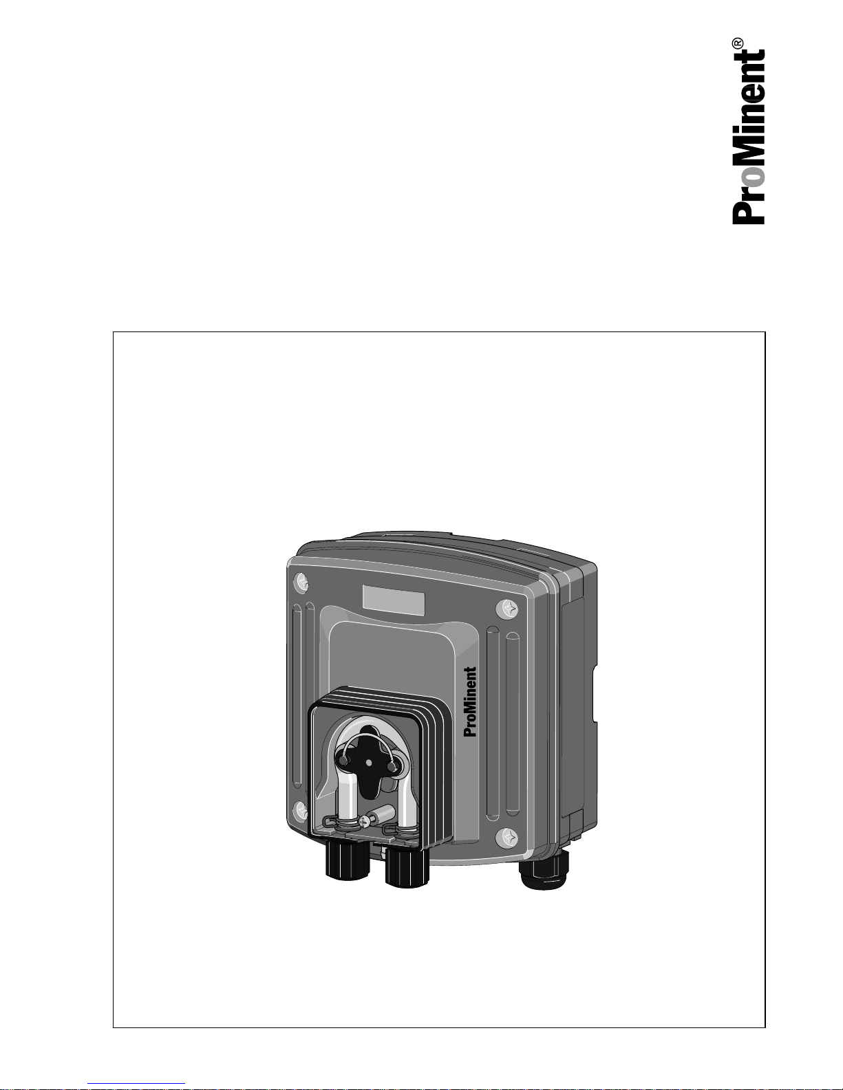
ProMinent® dulco®flex
DF2a
Assembly and operating instructions
A1666
A1666
EN
Original instructions (2006/42/EC)Part number 984881 BA DX 016 11/14 EN
Please carefully read these operating instructions before use. · Do not discard.
The operator shall be liable for any damage caused by installation or operating errors.
The latest version of the operating instructions are available on our homepage.
Page 2

General non-discriminatory approach
In order to make it easier to read, this
document uses the male form in
grammatical structures but with an
implied neutral sense. It is aimed
equally at both men and women. We
kindly ask female readers for their
understanding in this simplification of
the text.
Supplementary information
Read the following supplementary
information in its entirety!
The following are highlighted sepa‐
rately in the document:
n Enumerated lists
Instructions
ð
Results of the instructions
Information
This provides important informa‐
tion relating to the correct opera‐
tion of the system or is intended to
make your work easier.
Safety information
Safety information are provided with
detailed descriptions of the endan‐
gering situation, see
Ä Chapter 2.1
‘Explanation of the safety information’
on page 7
Supplemental instructions
2
Page 3

Table of contents
1 About this pump......................................................................................... 4
2 Safety and responsibility............................................................................ 7
2.1 Explanation of the safety information................................................. 7
2.2 Safety notes....................................................................................... 8
2.3 Intended use.................................................................................... 10
2.4 Users' qualifications......................................................................... 11
3 Storage and Transport............................................................................. 13
4 Overview of equipment / Functional description...................................... 14
5 Assembly and Installation........................................................................ 15
5.1 Assembling the peristaltic pump...................................................... 15
5.2 Installing hose lines......................................................................... 17
5.3 Electrical installation of the peristaltic pump.................................... 18
6 Start up.................................................................................................... 21
7 Maintenance, repair and faults ............................................................... 22
7.1 Maintenance.................................................................................... 22
7.2 Repair.............................................................................................. 23
7.3 Troubleshooting............................................................................... 24
8 Decommissioning and disposal............................................................... 25
8.1 Disposal of used parts..................................................................... 25
9 Technical data......................................................................................... 27
9.1 Accessories..................................................................................... 31
9.2 Dimension sheet.............................................................................. 31
10 EC Declaration of Conformity for Machinery........................................... 32
11 Index........................................................................................................ 34
Table of contents
3
Page 4

1 About this pump
ProMinent® dulco®flex peristaltic
pumps are designed for use in private
swimming pools and hotel swimming
pools.
About this pump
4
Page 5

Identity code
DF2adulco®flex, version a
Pump type:
02041.5 bar; 0.4 litres
02081.5 bar; 0.8 litres
02161.5 bar; 1.6 litres
02241.5 bar; 2.4 litres
Hose material:
P
PharMed
®
T
Tygon
®
Design:
0
With ProMinent® logo
1
Without ProMinent® logo
Hydraulic connector:
0 Standard
9 Special connector 10 x 4, discharge side
Electrical connection:
A 230 V, 50/60 Hz
B 115 V, 50/60 Hz
Cable and plug:
0 without cable
1 with cable 2.0 m; open end
About this pump
5
Page 6

DF2adulco®flex, version a
4 with cable 0.8 m; open end
Control:
0 Mains power supply ON/OFF
Mounting type:
W Wall mounting
Accessories:
0 No accessories
1 Metering valve and foot valve;
suction and discharge line
About this pump
6
Page 7
2 Safety and responsibility
2.1 Explanation of the safety
information
Introduction
These operating instructions provide
information on the technical data and
functions of the product. These oper‐
ating instructions provide detailed
safety information and are provided
as clear step-by-step instructions.
The safety information and notes are
categorised according to the following
scheme. A number of different sym‐
bols are used to denote different sit‐
uations. The symbols shown here
serve only as examples.
DANGER!
Nature and source of the danger
Consequence: Fatal or very
serious injuries.
Measure to be taken to avoid this
danger
Danger!
– Denotes an immediate threat‐
ening danger. If this is disre‐
garded, it will result in fatal or
very serious injuries.
WARNING!
Nature and source of the danger
Possible consequence: Fatal or
very serious injuries.
Measure to be taken to avoid this
danger
Warning!
– Denotes a possibly hazardous
situation. If this is disregarded,
it could result in fatal or very
serious injuries.
CAUTION!
Nature and source of the danger
Possible consequence: Slight or
minor injuries, material damage.
Measure to be taken to avoid this
danger
Caution!
– Denotes a possibly hazardous
situation. If this is disregarded,
it could result in slight or minor
injuries. May also be used as
a warning about material
damage.
Safety and responsibility
7
Page 8

NOTICE!
Nature and source of the danger
Damage to the product or its sur‐
roundings
Measure to be taken to avoid this
danger
Note!
– Denotes a possibly damaging
situation. If this is disregarded,
the product or an object in its
vicinity could be damaged.
Type of information
Hints on use and additional infor‐
mation
Source of the information, addi‐
tional measures
Information!
–
Denotes hints on use and
other useful information. It
does not indicate a hazardous
or damaging situation.
2.2 Safety notes
WARNING!
Danger from hazardous sub‐
stances!
Possible consequence: Fatal or
very serious injuries.
Please ensure when handling
hazardous substances that you
have read the latest safety data
sheets provided by the manufac‐
ture of the hazardous substance.
The actions required are
described in the safety data sheet.
Check the safety data sheet regu‐
larly and replace, if necessary, as
the hazard potential of a sub‐
stance can be re-evaluated at any
time based on new findings.
The system operator is respon‐
sible for ensuring that these safety
data sheets are available and that
they are kept up to date, as well
as for producing an associated
hazard assessment for the work‐
stations affected.
Safety and responsibility
8
Page 9
WARNING!
Danger of electric shock
Mains voltage may be present
inside the pump housing.
Immediately disconnect the pump
from the mains power supply if the
pump housing has been dam‐
aged. Only return the pump to
service after an authorised repair.
CAUTION!
Warning of feed chemical
spraying around
The metering pump can generate
a multiple of its rated pressure.
Hydraulic parts may burst if a dis‐
charge line is blocked. -
Correctly install a relief valve in
the discharge line downstream of
the metering pump.
CAUTION!
Warning of backflow
Metering pumps are not abso‐
lutely leak-tight shut-off devices.
Use a shut-off valve, a solenoid
valve or a vacuum breaker for this
purpose.
CAUTION!
Personnel injury and material
damage
The pump can start to pump, as
soon as it is connected to mains
voltage.
Install an emergency cut-off
switch in the pump power supply
line or integrate the pump in the
emergency cut-off management of
the system.
CAUTION!
Device starts immediately
The unit does not have an On/Of
switch and begins to work as soon
as it is connected to the mains
voltage.
Only connect the device to the
mains voltage when all installation
work has been completed and the
pumped chemicals can no longer
escape in an uncontrolled
manner.
CAUTION!
Contact with chemicals
De-pressurise, drain and rinse the
hydraulic part of the unit before
working on it.
Safety and responsibility
9
Page 10

Protective equipment
The transparent cover on the
liquid end serves to prevent direct
contact with the rotor and
escaping chemicals in the event
of a ruptured hose.
Information in the event of an emer‐
gency
In the event of an electrical accident,
disconnect the mains cable from the
mains power supply or press the
emergency cut-off switch fitted on the
side of the system. If feed chemical is
escaping, switch off the pump by
pressing
[Stop/Start]
. If necessary
ensure that the hydraulic system
around the pump is at atmospheric
pressure. Adhere to the safety data
sheet for the feed chemical.
2.3 Intended use
n Only use the unit to meter liquid
media.
n Only use the unit in accordance
with the technical data and speci‐
fications outlined in the operating
instructions.
n Any other uses or modifications to
the system are prohibited
n Do not use the unit to meter gas‐
eous media or solids.
n Do not use the unit to meter flam‐
mable media.
n Only use the unit with further pro‐
tection (exterior housing, weather‐
proof roof) for external use. The
housing can be affected by direct
sunlight
n Only allow adequately qualified
and technically expert personnel
to operate the unit
n Observe the general limitations
with regard to viscosity limits,
chemical resistance and density refer also to the ProMinent®
Resistance List in the Product
Catalogue or at www.promi‐
nent.com!
n The pump is not intended for ope‐
ration in areas at risk from explo‐
sion.
All other uses or modifications are
prohibited.
Safety and responsibility
10
Page 11

2.4 Users' qualifications
WARNING!
Danger of injury with inadequately qualified personnel!
The operator of the plant / device is responsible for ensuring that the qualifi‐
cations are fulfilled.
If inadequately qualified personnel work on the unit or loiter in the hazard
zone of the unit, this could result in dangers that could cause serious injuries
and material damage.
– All work on the unit should therefore only be conducted by qualified per‐
sonnel.
– Unqualified personnel should be kept away from the hazard zone
Training Definition
Instructed per‐
sonnel
An instructed person is deemed to be a person who has
been instructed and, if required, trained in the tasks
assigned to him/her and possible dangers that could
result from improper behaviour, as well as having been
instructed in the required protective equipment and pro‐
tective measures.
Trained user A trained user is a person who fulfils the requirements
made of an instructed person and who has also received
additional training specific to the system from ProMinent
or another authorised distribution partner.
Trained qualified
personnel
A qualified employee is deemed to be a person who is
able to assess the tasks assigned to him and recognize
possible hazards based on his/her training, knowledge
and experience, as well as knowledge of pertinent regu‐
lations. The assessment of a person's technical training
can also be based on several years of work in the rele‐
vant field.
Safety and responsibility
11
Page 12

Training Definition
Electrician Electricians are deemed to be people, who are able to
complete work on electrical systems and recognize and
avoid possible hazards independently based on his/her
technical training and experience, as well as knowledge
of pertinent standards and regulations.
Electricians should be specifically trained for the working
environment in which the are employed and know the
relevant standards and regulations.
Electricians must comply with the provisions of the appli‐
cable statutory directives on accident prevention.
Customer Service
department
Customer Service department refers to service techni‐
cians, who have received proven training and have been
authorised by ProMinent to work on the system.
Note for the system operator
The pertinent accident prevention regulations, as well as all other generally
acknowledged safety regulations, must be adhered to!
Safety and responsibility
12
Page 13

3 Storage and Transport
Store and transport the unit in its orig‐
inal packaging.
Protect the unit against moisture and
the effects of chemicals, even while
still packaged.
Ambient conditions for storage and
transport
Permissible ambient temperature:
-10 ... 45 °C
Permissible storage temperature:
-10 ... 55 °C
Permissible medium temperature:
-10 ... 45 °C
Humidity: None. Rain and condensa‐
tion not permitted.
Other: No dust, no direct sunlight.
Storage and Transport
13
Page 14

4 Overview of equipment / Functional description
Overview of equipment
2
11
1
A
B
3
12
5
2
108
4
7
9
6
A1630
Fig. 1: Overview of equipment
1. Rollers with tensioning springs
2. Dosing head
3. Rotor
4. Pump hose
5. Hose connector, suction side
6. Leakage fitting
7. Hose connector, discharge side
8. Threaded connector
9. Wall bracket
10. Rear section of housing, power
end
11. Upper section of housing, power
end
12. Transparent cover
A. Drive unit
B. Liquid end
Functional description
An electric motor drives a rotor.
Spring-mounted rollers are fitted to
the ends of the rotors, which press
the pump hose against the inner cur‐
vature of the dosing head.
The peristaltic pump operates by the
rollers driving the feed chemical
through the pump hose. The feet
chemical is primed by the pump hose
returning to its initial position.
Overview of equipment / Functional description
14
Page 15

5 Assembly and Installation
n User qualification, mechanical
installation: trained qualified per‐
sonnel, see
Ä Chapter 2.4 ‘Users'
qualifications’ on page 11
n User qualification, electrical instal‐
lation: Electrical technician, see
Ä Chapter 2.4 ‘Users' qualifica‐
tions’ on page 11
General information on
installation and assembly
The unit is resistant to normal
atmospheres in plant rooms.
Permissible ambient temperature:
-10 ... 45 °C
Permissible medium temperature:
-10 ... 45 °C
Humidity: None. Rain and con‐
densation not permitted.
Other: No dust, no direct sunlight.
Please observe the applicable
national regulations and guide‐
lines during installation!
5.1 Assembling the peristaltic
pump
Wall mounting
2
1
A0273
Fig. 2: Removing the wall/tube
retaining bracket
1. Remove the wall/tube retaining
bracket. Pull the two snaphooks (1) outwards and push
upwards
2. Fold out the wall/tube retaining
bracket (2) and pull out in a
downwards direction
3. Mark two drill holes diagonally
to each other, using the wall/
tube retaining bracket as a
drilling template
4. Drill holes: Ø 8 mm, d = 50 mm
Assembly and Installation
15
Page 16

A0274
Fig. 3: Screw the wall/tube retaining
bracket in place using the washers
5. Screw the wall/tube retaining
bracket in place using the
washers
6. Suspend the peristaltic pump at
the top of the wall/tube retaining
bracket and, using light pres‐
sure, press it against the wall/
tube retaining bracket at the
bottom. Then press upwards
until the peristaltic pump audibly
snaps into position.
Pipe assembly
Pipe diameter
Pipe diameter: 25 mm to 60 mm.
2
1
A0273
Fig. 4: Removing the wall/tube
retaining bracket
1. Remove the wall/tube retaining
bracket. Pull the two snaphooks (1) outwards and push
upwards
2. Fold out the wall/tube retaining
bracket (2) and pull out in a
downwards direction
3. Secure the wall/tube retaining
bracket to the pipe with cable
ties (or pipe clamps).
Assembly and Installation
16
Page 17

A0275
3
2
1
Fig. 5: Suspend the peristaltic pump
and fix in place
4. Suspend the peristaltic pump
(1) at the top of the wall/tube
retaining bracket and, using
light pressure, press it against
the wall/tube retaining bracket
at the bottom (2). Then press
upwards (3) until the peristaltic
pump audibly snaps into posi‐
tion.
5.2 Installing hose lines
Only use original hoses with the
specified hose dimensions 6 x 4
mm or 10 x 4 mm, otherwise the
durability of the connection cannot
be guaranteed.
Avoid reducing the hose sizes.
The hose lines used must be able
to withstand twice the operating
pressure of the peristaltic pump.
Assembly and Installation
17
Page 18

Assembling the suction and discharge
lines.
4
2
1
3
A1631
Fig. 6: Installation diagram
1. Peristaltic pump
2. Chemical tank
3. Foot valve or suction lance
4. Injection valve
1. Cut the end of the hose at right
angles.
2. Unscrew a union nut and slide
the union nut over the pump
hose.
3. Push the tube end over the
nozzle until it will go not further.
4. Connect the discharge line to
the right hose connector.
5. Connect the suction line to the
left hose connector.
6. Tighten the union nuts.
7. Shorten the free end of the suc‐
tion line so that the foot valve
hangs just above the base of
the tank. With feed chemicals
that can form sediment, ensure
that the foot valve is suspended
a minimum of 50 mm above the
base of the tank.
8. Guide a hose line into the
storage tank from the leakage
fitting.
5.3 Electrical installation of the
peristaltic pump
–
Only carry out the electrical
installation once the mechan‐
ical and hydraulic installations
have been completed.
–
During installation, ensure that
the mains cable is de-ener‐
gised and has been secured
to prevent it from being
switched on again.
–
Fit a short-circuit fuse during
installation.
–
Fit an Off switch for the mains
power supply during installa‐
tion.
Assembly and Installation
18
Page 19

Mains cable
Let the mains cable project from
the housing so that the front sec‐
tion of the housing can be
removed.
Remove around 120 mm from the
outer insulation of the mains
cable.
N
L
gelb/grün
yellow/green
A1632
Fig. 7: Terminal diagram
1. Loosen the four screws and
remove the upper part of the
housing
2. Break out the small bore hole at
the far right on the underside of
the housing
3. Screw the required threaded
connector in and tighten it prop‐
erly (not the clamping screw)
4. Insert the reducing insert into
the threaded connector
depending on the cable crosssection used
5. Guide the mains cable into the
threaded connector
6. Insulate the mains cable and
press on the corresponding
cable end sleeves
7. Connect the mains cable
accordingly, see Fig. 7 (protec‐
tive conductor connection)
Assembly and Installation
19
Page 20

8. Tighten the clamping nut of the
threaded connector so that they
are properly sealed
9. Place the front section of the
housing on the read section of
the housing
10.
Once again check that the
seal is seated properly. Pro‐
tection class IP 65 is only
achieved if it is correctly
assembled.
Manually tighten the four
housing screws
Assembly and Installation
20
Page 21

6 Start up
n User qualification: trained user,
see
Ä Chapter 2.4 ‘Users' qualifi‐
cations’ on page 11
WARNING!
Danger from hazardous sub‐
stances!
Possible consequence: Fatal or
very serious injuries.
Please ensure when handling
hazardous substances that you
have read the latest safety data
sheets provided by the manufac‐
ture of the hazardous substance.
The actions required are
described in the safety data sheet.
Check the safety data sheet regu‐
larly and replace, if necessary, as
the hazard potential of a sub‐
stance can be re-evaluated at any
time based on new findings.
The system operator is respon‐
sible for ensuring that these safety
data sheets are available and that
they are kept up to date, as well
as for producing an associated
hazard assessment for the work‐
stations affected.
Only operate the pump after
proper installation.
Only operate the pump once the
transparent cover has been
screwed on.
1. Disconnect the discharge hose
from the hose connector.
2. Allow the peristaltic pump to run
until the pump hose is filled.
3. Switch off the peristaltic pump
after the pump hose has been
filled
4. Re-connect the discharge hose
to the hose connector.
5. Allow the peristaltic pump to run
for a short time
ð
The peristaltic pump is now
ready for operation.
6. Check the threaded connectors
and pipe system for leak-tight‐
ness
Start up
21
Page 22

7 Maintenance, repair and faults
n User qualification: trained user,
see
Ä Chapter 2.4 ‘Users' qualifi‐
cations’ on page 11
WARNING!
Danger from hazardous sub‐
stances!
Possible consequence: Fatal or
very serious injuries.
Please ensure when handling
hazardous substances that you
have read the latest safety data
sheets provided by the manufac‐
ture of the hazardous substance.
The actions required are
described in the safety data sheet.
Check the safety data sheet regu‐
larly and replace, if necessary, as
the hazard potential of a sub‐
stance can be re-evaluated at any
time based on new findings.
The system operator is respon‐
sible for ensuring that these safety
data sheets are available and that
they are kept up to date, as well
as for producing an associated
hazard assessment for the work‐
stations affected.
7.1 Maintenance
After extended periods of idleness
If the peristaltic pump has not
pumped gaseous or adhesive feed
chemicals for a longer period of time,
checked whether the state of the
hoses permits reliable operation.
Approx. every six months
Checks:
n Visual control of the liquid end
n Check the pump hose for leak-
tightness
n Check the pump connectors for
leak-tightness
Shorter maintenance intervals may be
necessary depending on the feed
chemicals used and operating condi‐
tions.
Approx. annually
Replace the pump hose.
This can lead to a reduction in
pump capacity over time
depending on the operating condi‐
tions. Therefore replace the pump
hose earlier if necessary.
The power end is maintenance-free.
Maintenance, repair and faults
22
Page 23

7.2 Repair
Ensure that the system is at
atmospheric pressure.
Drain the pump hose and thor‐
oughly rinse it with a suitable
medium.
Only turn the rotor in a clockwise
direction.
Changing the pump hose
1. Loosen the suction hose and
the discharge hose from the
hose connectors
2. Loosen the fixing bolt on the
transparent cover and remove
the transparent cover
3. Remove the suction-side hose
connector (left) from its
mounting
4. Carefully pull the pump hose out
under the rollers
5.
When doing so, ensure that
the rounded sides of the
hose connectors are
pointing towards the unit.
Insert the two hose connectors
of the new pump hose into the
two mountings.
6. Briefly switch on the motor. The
pump hose moves into the cor‐
rect position under the rollers
7. Replace the transparent cover
on the housing and screw it into
place
8. Fix the suction hose and the
discharge hose to the hose con‐
nectors
Maintenance, repair and faults
23
Page 24

7.3 Troubleshooting
Fault Cause Remedy
The peristaltic pump no
longer reaches full
pump capacity
The pump hose has
lost its elasticity
Replace the pump hose,
see
Ä Chapter 7.2 ‘Repair’
on page 23
In all other cases, notify your service technician or your ProMinent branch.
Maintenance, repair and faults
24
Page 25

8 Decommissioning and disposal
n User qualification: instructed user,
see
Ä Chapter 2.4 ‘Users' qualifi‐
cations’ on page 11
WARNING!
Danger from hazardous sub‐
stances!
Possible consequence: Fatal or
very serious injuries.
Please ensure when handling
hazardous substances that you
have read the latest safety data
sheets provided by the manufac‐
ture of the hazardous substance.
The actions required are
described in the safety data sheet.
Check the safety data sheet regu‐
larly and replace, if necessary, as
the hazard potential of a sub‐
stance can be re-evaluated at any
time based on new findings.
The system operator is respon‐
sible for ensuring that these safety
data sheets are available and that
they are kept up to date, as well
as for producing an associated
hazard assessment for the work‐
stations affected.
De-energise the mains cable and
ensure that it cannot be switched
on again during decommissioning.
Thoroughly clean the housing and
especially the pump hose of
chemicals and dirt when decom‐
missioning the pump!
1. Disconnect the unit from the
mains power supply
2. Drain the pump hose and thor‐
oughly rinse it with a suitable
medium
Observe storage conditions for tem‐
porary decommissioning.
8.1 Disposal of used parts
n Users' qualification: instructed
persons, see
Ä Chapter 2.4
‘Users' qualifications’ on page 11
NOTICE!
Regulations governing disposal of
used parts
– Note the current national reg‐
ulations and legal standards
which apply in your country
Decommissioning and disposal
25
Page 26

ProMinent Dosiertechnik GmbH, Hei‐
delberg will take back decontami‐
nated used devices providing that
they are covered by adequate
postage.
Decommissioning and disposal
26
Page 27

9 Technical data
Pump
type
Max. pump capacity*
at maximum back pressure
Connector
size
Ø x Ø
Suct
ion
lift**
Pri‐
ming
lift**
Permis‐
sible
priming
pres‐
sure on
the suc‐
tion
side**
bar 50 Hz 60 Hz mm m m bar
l/h l/h
204 1,5 0,4 0,48 6 x 4, 10 x 4 4 2 0,5
208 1,5 0,8 0,96 6 x 4, 10 x 4 4 2 0,5
216 1,5 1,6 1,92 6 x 4, 10 x 4 4 2 0,5
224 1,5 2,4 2,88 6 x 4, 10 x 4 4 2 0,5
*depending on the back pressure.
** The values were determined with water.
Switching-on duration:
100 %
Precision
The starting precision of the pump
capacity is ± 10 %. The pump
capacity can fall during operation due
to damage to the elasticity of the
pump hose.
Technical data
27
Page 28

Materials specifications and resistance
Part Material
Pump hose
PharMed® or Tygon
®
Hose connectors PVC
Dosing head PPE
Transparent cover PC
Housing (power end) PPE-GF
Wall bracket PPE-GF
Housing seal Silicone
Housing screws M4 A2
Cable threaded connectors
Polyamide/Neoprene
®
Design for fragrance metering
Part Material
Pump hose FPM
Hose connectors PVC
Dosing head PA12
Transparent cover PA12
Housing (power end) PP+GF
Wall bracket PA+GF
Housing seal Silicone
Housing screws M4 A2
Cable threaded connectors
Polyamide/Neoprene
®
Technical data
28
Page 29

Chemical resistance
The unit is resistant to normal atmos‐
pheres in plant rooms.
Resistance to other chemicals, see
ProMinent Resistance List (home‐
page or Product Catalogue).
UV resistance
n Do not use the unit with direct UV
radiation.
Technical data
29
Page 30

No short-circuit fuse is fitted and needs to be taken into consideration in
installation.
Description Data
Dimensions and weights:
Dimensions: 126 x 136 x 105 mm (WxHxD)
PG 9 clamping range Ø 3.5 - Ø 8 mm, spanner
size 19.
Weight: Total weight (including installation material)
approx. 750 g
Total weight (net), approx. 600 g
Electrical data:
Connection voltage: 115 V ±10 % at 50/60 Hz
230 V ±10 % at 50/60 Hz
Power consumption: approx. 5 W
Switching-on duration: 100 %
Degree of protection: Degree of protection 1 - according to DIN EN
60335-1 (protective conductor connection
required)
Protection against accidental
contact and humidity:
IP 65
Temperature data: Permissible ambient temperature: -10 ... 45 °C
Permissible storage temperature: -10 ... 55 °C
Technical data
30
Page 31

Description Data
Permissible medium temperature: -10 ... 45 °C
Sound pressure level: < 30 dB (A) at maximum back pressure (water)
according to DIN EN 12639
9.1 Accessories
Description Order number
Installation material for dulco®flex, com‐
plete
1007297
Mains cable via identity code
Injection valve and foot valve via identity code
Suction lances see Product Catalogue
9.2 Dimension sheet
29
136
126
105
59.5
78
90
A1633
Fig. 8: Dimension sheet for DF2a
Technical data
31
Page 32

10 EC Declaration of Conformity for Machinery
In accordance with DIRECTIVE
2006/42/EC OF THE EUROPEAN
PARLIAMENT AND OF THE
COUNCIL, Appendix I, BASIC
HEALTH AND SAFETY REQUIRE‐
MENTS, section 1.7.4.2. C.
EC Declaration of Conformity for Machinery
32
Page 33

We,
n ProMinent Dosiertechnik GmbH
n Im Schuhmachergewann 5 - 11
n DE - 69123 Heidelberg,
hereby declares that the product specified in the following, complies with the rel‐
evant basic health and safety requirements of the EC Directive, on the basis of
its functional concept and design and in the version distributed by us. This dec‐
laration loses its validity in the event of a modification to the product not agreed
with us.
Designation of the
product:
Peristaltic pump DF2a
Serial number: refer to nameplate on the device
Relevant EC direc‐
tives:
EC Machinery Directive (2006/42/EC)
EC EMC Directive (2004/108/EC)
Compliance with the protection targets of the Low
Voltage Directive (2006/95/EC) according to
Appendix I, No. 1.5.1 of the Machinery Directive
2006/42/EC
Harmonised standards
applied, in particular:
EN 809
EN 60335-1
EN 60335-2-41
EN 61000-6-1
EN 61000-6-3
EN 61000-6-4
Date: 05/03/2012
EC Declaration of Conformity for Machinery
33
Page 34

11 Index
A
Ambient conditions ............13
Ambient temperature ..........13
Applied harmonised standards ...33
C
Changing the pump hose .......23
Components of the device ......14
D
Declaration of Conformity .......33
Designation of the product ......33
F
Fixing materials ...............15
Fragrance metering ............28
Functional description ..........14
G
General information on installation
and assembly ................15
General non-discriminatory
approach .....................2
I
Installation ..................15
M
Maintenance: After extended
periods of idleness ............22
Maintenance: approx. annually ...22
Maintenance: approx. every six
months .....................22
N
non-discriminatory approach ......2
P
Pipe assembly ...............16
Pipe diameter: 25 mm to 60 mm. . 16
Q
Question: Where do I find the
Declaration of Conformity? ......33
Question: Which standards are
complied with? ...............33
R
Relevant EC directives .........33
S
Safety information ..............7
Serial number ................33
Standards complied with ........33
T
Transparent cover .............21
U
Users' qualifications ...........11
W
Wall mounting ................15
Washer .....................15
Index
34
Page 35

35
Page 36

984881, 1, en_GB
© 2014
ProMinent GmbH
Im Schuhmachergewann 5 - 11
69123 Heidelberg
Germany
Telephone: +49 6221 842-0
Fax: +49 6221 842-419
Email: info@prominent.com
Internet: www.prominent.com
 Loading...