

Page 1
Assembly and operating instructions
A2700
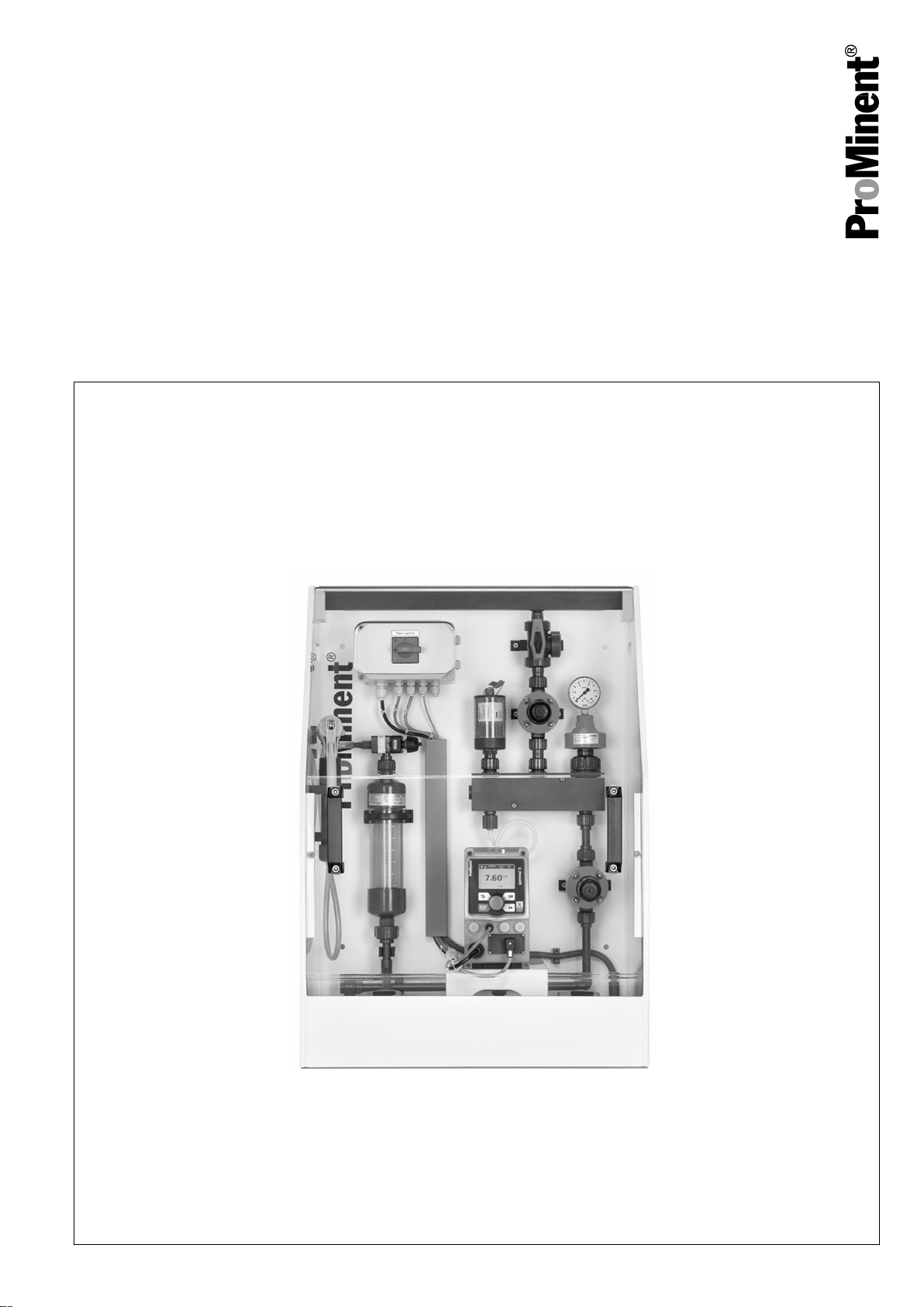
Universal Metering System DSUa Mini
Metering frame complete with all pipework
EN
Please carefully read these operating instructions before use. · Do not discard.
The operator shall be liable for any damage caused by installation or operating errors.
The latest version of the operating instructions are available on our homepage.
Original operating instructions (2006/42/EC)982011 Version: BA DST 012 02/19 EN
Page 2
Supplemental directives
General non-discriminatory approach
Supplementary information
In order to make it easier to read, this document uses the male
form in grammatical structures but with an implied neutral sense. It
is aimed equally at both men and women. We kindly ask female
readers for their understanding in this simplification of the text.
Please read the supplementary information in its entirety.
Information
This provides important information relating to the
correct operation of the unit or is intended to make
your work easier.
Warning information
Warning information includes detailed descriptions of the haz‐
ardous situation, see
tion’ on page 14
Ä Chapter 2.2 ‘Labelling of Warning Informa‐
.
The following symbols are used to highlight instructions, links, lists,
results and other elements in this document:
Tab. 1: More symbols
Symbol Description
Action, step by step.
⇨ Outcome of an action.
Links to elements or sections of these instructions or other applicable documents.
n
[Button]
List without set order.
Display element (e.g. indicators).
Operating element (e.g. button, switch).
‘Display /GUI’
CODE
Screen elements (e.g. buttons, assignment of function keys).
Presentation of software elements and/or texts.
2
Page 3

Table of contents
Table of contents
1 About this product................................................................. 4
1.1 Technical details........................................................... 4
1.2 Identity code................................................................. 5
1.3 Metering system, 1 pump, 1 point of injection.............. 9
1.4 Metering system, 2 pumps, 1 point of injection........... 10
1.5 Metering system, 2 pumps, 2 points of injection......... 11
2 Safety and responsibility..................................................... 13
2.1 User qualification........................................................ 13
2.2 Labelling of Warning Information................................ 14
2.3 General safety notes................................................... 15
2.4 Intended Use.............................................................. 18
3 Storage and Transport........................................................ 19
4 Assembly and installation................................................... 20
4.1 General....................................................................... 20
4.2 Installation on the floor................................................ 21
4.3 Installation with stainless steel bracket....................... 22
4.4 Installation on the wall................................................ 22
4.5 Connect the suction lance level gauge....................... 23
5 Commissioning................................................................... 24
5.1 Leaks and Emissions.................................................. 24
5.2 Personal Protective Equipment (PPE)........................ 25
5.3 Commissioning Test Run............................................ 25
5.4 Connecting the Chemical Tank for Commissioning.... 26
6 Operation of the Metering System...................................... 27
7 Maintenance and Troubleshooting...................................... 28
7.1 Maintenance............................................................... 29
7.2 Troubleshooting.......................................................... 31
8 Decommissioning and disposal.......................................... 33
8.1 Disposal of used parts................................................ 34
9 Technical data..................................................................... 35
10 Drawings............................................................................. 37
10.1 Metering system, 1 pump, 1 point of injection.......... 37
10.2 Metering system, 2 pumps, 1 point of injection......... 38
10.3 Metering system, 2 pumps, 2 points of injection....... 39
11 Flow diagram of DSUa mini (PID)....................................... 40
11.1 Legend for flow diagrams......................................... 40
11.2 Flow diagram of DSUa mini 1 (PID).......................... 41
11.3 Flow diagram of DSUa mini 2 (PID).......................... 42
11.4 Flow diagram of DSUa mini 3 (PID).......................... 43
12 Electrical wiring diagram..................................................... 44
12.1 Electrical Wiring Diagram, 1062129, 1 Pump........... 44
12.2 Electrical wiring diagram, 2 pumps........................... 46
13 Declaration of Conformity for Machinery............................. 48
14 Index................................................................................... 49
3
Page 4
A2355
About this product
1 About this product
1.1 Technical details
The metering system DULCODOS® universal combines standard
components with the solenoid-driven metering pump you have
selected. For the reliable metering of liquid chemicals.
Technical details:
n Solenoid-driven metering pumps Beta® 4/5
n delta
®
n gamma/ X
n Dimensions: 850x580x410 mm or 1000x680x410 mm (H x W x
D)
n Material combinations: PP/FKM or PVC/EPDM. Pay attention
to compatibility with the feed chemical.
n Relief valves to protect the pipework
n Manometer
n Collecting pan with leak sensor
n Flushing connectors
n Terminal box with master switch
n The assembly frame is available in 6 standard colours
Nameplate
WARNING!
Danger from hazardous substances!
Possible consequence: Fatal or very serious inju‐
ries.
Please ensure when handling hazardous sub‐
stances that you have read the latest safety data
sheets provided by the manufacture of the haz‐
ardous substance. The actions required are
described in the safety data sheet. Check the
safety data sheet regularly and replace, if neces‐
sary, as the hazard potential of a substance can be
re-evaluated at any time based on new findings.
The system operator is responsible for ensuring
that these safety data sheets are available and that
they are kept up to date, as well as for producing
an associated hazard assessment for the worksta‐
tions affected.
Field of application
Fig. 1: Nameplate
Metering of liquid chemicals, e.g.
n Cooling water treatment
n Waste water and process water treatment
n Paper industry
4
Page 5
1.2 Identity code
DSUa DULCODOS universal mini
Pipework / Seal / Function
A PVC, EPDM, for 1 pump and 1 point of injection
B PVC, EPDM, for 2 pumps and 1 point of injection
C PVC, EPDM, for 2 pumps and 2 points of injection
D PP, FKM, for 1 pump and 1 point of injection
E PP, FKM, for 2 pumps and 1 point of injection
F PP, FKM, for 2 pumps and 2 points of injection
Assembly frame
A PP, white, 850x580x410 mm (HxWxD) for (A/D)
B PP, white, 1000x680x410 mm (HxWxD) for (B/E)
C PP, white, 850x880x410 mm (HxWxD) for (C/F)
Design
About this product
00 with ProMinent logo
01 without ProMinent logo
Pulsation damper
0 none
1 1 x pulsation damper PVC/ EPDM
2 1 x pulsation damper PP/FKM
3 2 x pulsation damper PVC/ EPDM
4 2 x pulsation dampers PP/FKM
Hydraulic connectors
0 Insert
1 Hose nipple 6x4
2 Hose nipple 8x5
3 Hose nipple 12x9
4 Pressure hose nozzle DN10
5 Pressure hose nozzle 1/2" NPT
Flushing connectors
0 closed
1 Pressure hose nozzle DN10
2
Gardena
®
3 Pressure hose nozzle 1/2" NPT
Splash guard
0 none
A Splash guard for (A/D)
B Splash guard for (B/E)
5
Page 6

About this product
DSUa DULCODOS universal mini
C Splash guard for (C/F)
Stainless steel bracket
D No stainless steel bracket
A Stainless steel bracket (H= 150 mm) + machine feet for (A/D)
B Stainless steel bracket (H= 150 mm) + machine feet for (B/E)
C Stainless steel bracket (H= 150 mm) + machine feet for (C/F)
Pump 1
00 no pump
Beta® 4
41 10 bar / 0.74 l/h, BT4b 1000 PVT, 6x4
42 16 bar / 2.2 l/h, BT4b 1602 PVT, 6x4
43 16 bar / 3.60 l/h, BT4b 1604 PVT, 6x4
44 7 bar / 7.10 l/h, BT4b 0708 PVT, 8x5
45 4 bar / 12.30 l/h, BT4b 0413 PVT, 8x5
46 2 bar / 19.00 l/h, BT4b 0220 PVT, 12x9
Beta® 5
51 10 bar / 6.80 l/h, BT5b 1008 PVT, 8x5
52 7 bar / 11.0 l/h, BT5b 0713 PVT, 8x5
53 4 bar / 17.10 l/h, BT5b 0420 PVT, 12x9
54 2 bar / 32.00 l/h, BT5b 0232 NPE, 12x9
delta®:
D1 16 bar / 11.3 l/h, DLTa 1612 PVT, 8x5
D2 10 bar / 19.1 l/h, DLTa 1020 PVT, 12x9
D3 7 bar / 29.2 l/h, DLTa 0730 PVT, 12x9
D4 4 bar / 49.0 l/h, DLTa 0450 PVT, DN10
D5 2 bar / 75.0 l/h, DLTa 0280 PVT, DN10
gamma/ X®:
X1 16 bar / 3.6 l/h, GMXa 1604 PVT, 6x4
X2 7 bar / 7.6 l/h, GMXa 0708 PVT, 8x5
X3 10 bar / 9.0 l/h, GMXa 1009 PVT, 8x5
X4 4 bar / 13.5 l/h, GMXa 0414 PVT 8x5
X5 7 bar / 14.5 l/h, GMXa 0715 PVT, 8x5
X6 2 bar / 19.7 l/h, GMXa 0220 PVT, 12x9
X7 4 bar / 24.0 l/h, GMXa 0424 PVT, 12x9
X8 2 bar / 45.0 l/h, GMXa 0245 PVT, 12x9
Pump 2
00 no pump
6
Page 7
DSUa DULCODOS universal mini
About this product
Beta® 4
41 10 bar / 0.74 l/h, BT4b 1000 PVT, 6x4
42 16 bar / 2.2 l/h, BT4b 1602 PVT, 6x4
43 16 bar / 3.60 l/h, BT4b 1604 PVT, 6x4
44 7 bar / 7.10 l/h, BT4b 0708 PVT, 8x5
45 4 bar / 12.30 l/h, BT4b 0413 PVT, 8x5
46 2 bar / 19.00 l/h, BT4b 0220 PVT, 12x9
Beta® 5
51 10 bar / 6.80 l/h, BT5b 1008 PVT, 8x5
52 7 bar / 11.0 l/h, BT5b 0713 PVT, 8x5
53 4 bar / 17.10 l/h, BT5b 0420 PVT, 12x9
54 2 bar / 32.00 l/h, BT5b 0232 NPE, 12x9
delta®:
D1 16 bar / 11.3 l/h, DLTa 1612 PVT, 8x5
D2 10 bar / 19.1 l/h, DLTa 1020 PVT, 12x9
D3 7 bar / 29.2 l/h, DLTa 0730 PVT, 12x9
D4 4 bar / 49.0 l/h, DLTa 0450 PVT, N10
D5 2 bar / 75.0 l/h, DLTa 0280 PVT, DN10
gamma/ X®:
X1 16 bar / 3.6 l/h, GMXa 1604 PVT, 6x4
X2 7 bar / 7.6 l/h, GMXa 0708 PVT, 8x5
X3 10 bar / 9.0 l/h, GMXa 1009 PVT, 8x5
X4 4 bar / 13.5 l/h, GMXa 0414 PVT, 8x5
X5 7 bar / 14.5 l/h, GMXa 0715 PVT, 8x5
X6 2 bar / 19.7 l/h, GMXa 0220 PVT, 12x9
X7 4 bar / 24.0 l/h, GMXa 0424 PVT, 12x9
X8 2 bar / 45.0 l/h, GMXa 0245 PVT, 12x9
Operating instructions
CS Czech
EN German
EN English
ES Spanish
FR French
IT Italian
PT Portuguese
All other languages are available on request.
7
Page 8

About this product
DSUa DULCODOS universal mini
Certification
01 CE certification
8
Page 9
1.3 Metering system, 1 pump, 1 point of injection
600
1
2
13
4
5
6
7
8
13
10
A
C
B
11
410
10
58010
320
300
12
9
63 40
127
52
850
110
150
A2699
About this product
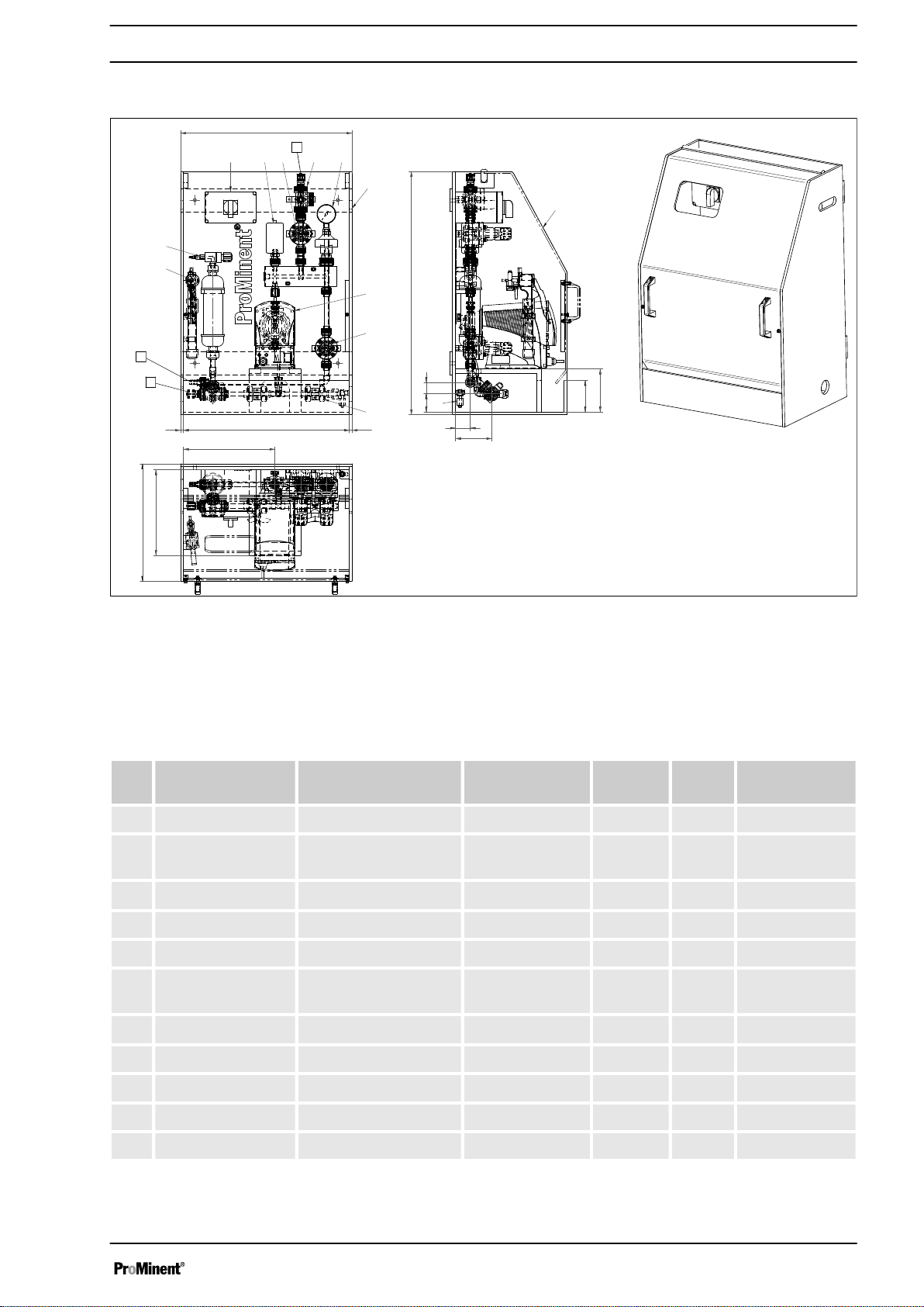
Fig. 2: Metering system, 1 pump, 1 point of injection, all dimensions in mm
A Feed
B Outlet
C Drain
Not shown Connecting parts for flushing pipe DN10,
2 no.
# Name Material/type Dimension Material Quan‐
Part number
tity
1 Assembly frame - 600x850x400 PP 1 -
2 Metering pump To be selected by the
3 Pulsation damper
customer.
Hidracar® U001
- - 1 -
0.09 litres PVC-U 1 1057944
4 Manometer MDM902 d25 / G1/4" PVC-U 1 1030362
5 DHV DHV-U DN10 PVC-U 1 1037765
6 Back pressure
valve
7 Vacuum pump
DHV-U DN10 PVC-U 1 1037765
Hubinont
®
MI8121 - 1 1031565
8 Vacuum cylinder - DN10 PVC-U 1 1025699
9 Ball valve 546 DN10 PVC-U 2 1024538
10 Level switch PP1/PE - - 1 142086
11 Splash guard PVC glass - - 1 -
9
Page 10
700
10 680
10
1000
63 40
110
150
52
126
410
300
90210
360
410 180
1
2
3
4
5
6
7
8
9
10
11
12 13
14
A
C
B
46
A2701
About this product
# Name Material/type Dimension Material Quan‐
Part number
tity
12 Terminal box - 180x110x90 mm - 1 1036995
13 3-way ball valve 543 DN10 PVC-U 2 1043568
1.4 Metering system, 2 pumps, 1 point of injection
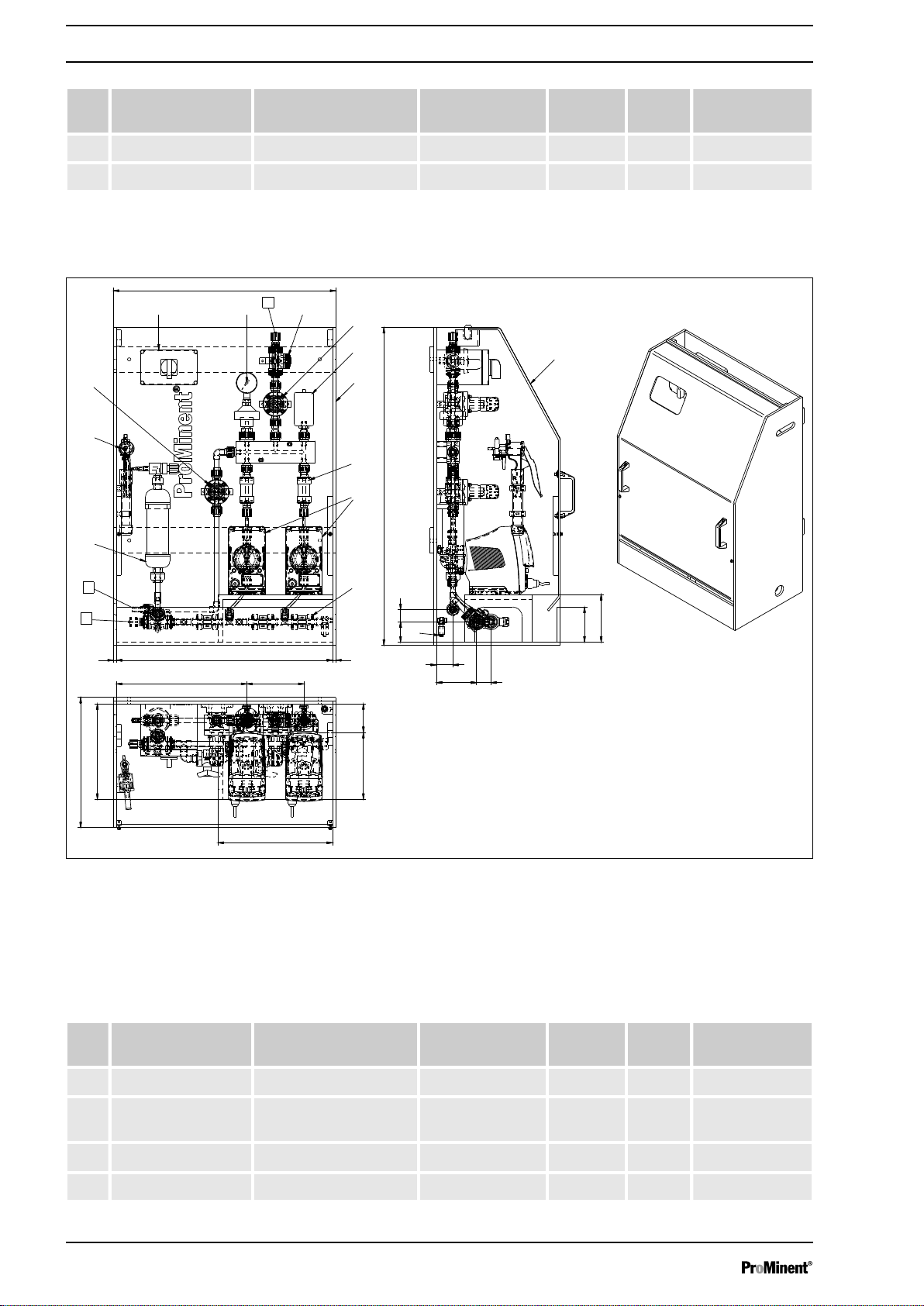
Fig. 3: Metering system, 2 pumps, 1 point of injection
A Feed
B Outlet
C Drain
Not shown Connecting parts for flushing pipe DN10,
# Name Material/type Dimension Material Quan‐
1 Assembly frame - 700x1000x400 PP 1 -
2 Metering pump To be selected by the
3 Pulsation damper
4 Manometer MDM902 d25 / G1/4" PVC-U 1 1030362
2 no.
Part number
tity
customer.
Hidracar® U001
- - 2 -
0.09 litres PVC-U 1 1057944
10
Page 11
900
880
10
10
850
63
40
52
127
46
110
150
412
300
460 290
A
C
B
B
1
2
3
4
5
6
7
8
9
10
11
12
13
A2702
About this product
# Name Material/type Dimension Material Quan‐
Part number
tity
5 DHV DHV-U DN10 PVC-U 1 1037765
6 Back pressure
DHV-U DN10 PVC-U 1 1037765
valve
7 Vacuum pump
Hubinont
®
MI8121 - 1 1031565
8 Vacuum cylinder - DN10 PVC-U 1 1025699
9 Ball valve 546 DN10 PVC-U 3 1024538
10 Level switch PP1/PE - - 1 142086
11 Splash guard PVC glass - - 1 -
12 Terminal box - 180x110x90 mm - 1 1036995
13 3-way ball valve 543 DN10 PVC-U 2 1043568
14 Non-return valve 360 ND10 PVC-U 2 -
1.5 Metering system, 2 pumps, 2 points of injection
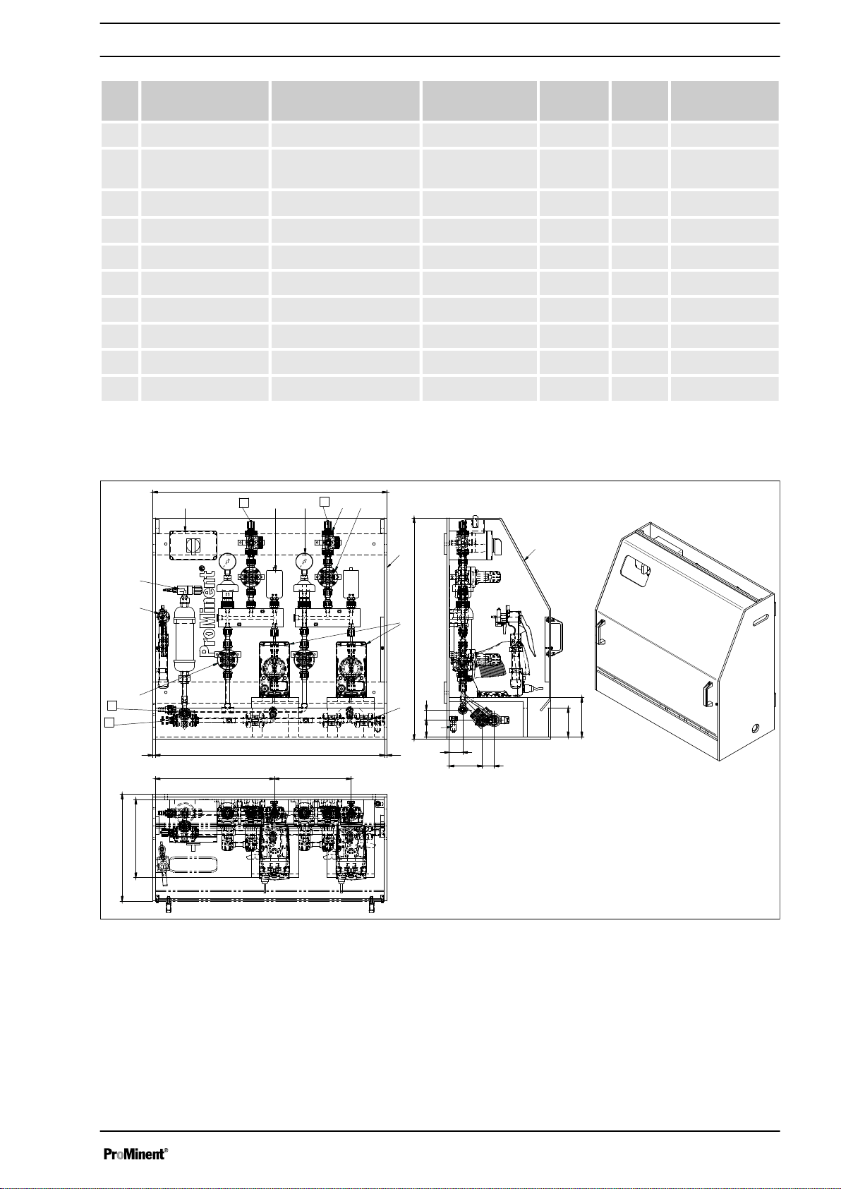
Fig. 4: Metering system, 2 pumps, 2 points of injection
A Feed
B Outlet
C Drain
Not shown Connecting parts for flushing pipe DN10,
2 no.
11
Page 12

About this product
# Name Material/type Dimension Material Quan‐
Part number
tity
1 Assembly frame - 700x1000x400 PP 1 -
2 Metering pump To be selected by the
- - 2 -
customer.
3 Pulsation damper
Hidracar® U001
0.09 litres PVC-U 2 1057944
4 Manometer MDM902 d25 / G1/4" PVC-U 2 1030362
5 DHV DHV-U DN10 PVC-U 2 1037765
6 Back pressure
DHV-U DN10 PVC-U 2 1037765
valve
7 Vacuum pump
Hubinont
®
MI8121 - 1 1031565
8 Vacuum cylinder - DN10 PVC-U 1 1025699
9 Ball valve 546 DN10 PVC-U 3 1024538
10 Level switch PP1/PE - - 1 142086
11 Splash guard PVC glass - - 1 -
12 Terminal box - 180x110x90 mm - 1 1036995
13 3-way ball valve 543 DN10 PVC-U 3 1043568
12
Page 13
2 Safety and responsibility
2.1 User qualification
Safety and responsibility
WARNING!
Danger of injury with inadequately qualified per‐
sonnel
The operator of the system / equipment is respon‐
sible for ensuring that the qualifications are ful‐
filled.
If inadequately qualified personnel work on the unit
or loiter in the hazard zone of the unit, this could
result in dangers that could cause serious injuries
and material damage.
– All work on the unit should therefore only be
conducted by qualified personnel.
– Unqualified personnel should be kept away
from the hazard zone.
The pertinent accident prevention regulations, as
well as all other generally acknowledged safety
regulations, must be adhered to.
Training Definition
Instructed personnel An instructed person is deemed to be a person who has been instructed and,
if required, trained in the tasks assigned to him and possible dangers that
could result from improper behaviour, as well as having been instructed in the
required protective equipment and protective measures.
Trained user A trained user is a person who fulfils the requirements made of an instructed
person and who has also received additional training specific to the system
from the manufacturer or another authorised distribution partner.
Trained, qualified per‐
sonnel
Electrical technician An electrical technician is able to complete work on electrical systems and rec‐
A trained, qualified employee is deemed to be a person who is able to assess
the tasks assigned to him and recognize possible hazards based on his
training, knowledge and experience, as well as knowledge of pertinent regula‐
tions. A trained, qualified employee must be able to perform the tasks
assigned to him independently with the assistance of drawing documentation
and parts lists. The assessment of a person's technical training can also be
based on several years of work in the relevant field.
ognise and avoid possible dangers independently based on his technical
training and experience as well as knowledge of pertinent standards and regu‐
lations. An electrical technician must be able to perform the tasks assigned to
him independently with the assistance of drawing documentation, parts lists,
terminal and circuit diagrams. The electrical technician must be specifically
trained for the working environment in which the electrical technician is
employed and be conversant with the relevant standards and regulations.
Service The Service department refers to service technicians, who have received
proven training and have been authorised by the manufacturer to work on the
system.
13
Page 14
Safety and responsibility
2.2 Labelling of Warning Information
Introduction
These operating instructions provide information on the technical
data and functions of the product. These operating instructions pro‐
vide detailed warning information and are provided as clear stepby-step instructions.
The warning information and notes are categorised according to
the following scheme. A number of different symbols are used to
denote different situations. The symbols shown here serve only as
examples.
DANGER!
Nature and source of the danger
Consequence: Fatal or very serious injuries.
Measure to be taken to avoid this danger.
Description of hazard
– Denotes an immediate threatening danger. If
the situation is disregarded, it will result in fatal
or very serious injuries.
WARNING!
Nature and source of the danger
Possible consequence: Fatal or very serious inju‐
ries.
Measure to be taken to avoid this danger.
– Denotes a possibly hazardous situation. If the
situation is disregarded, it could result in fatal
or very serious injuries.
CAUTION!
Nature and source of the danger
Possible consequence: Slight or minor injuries.
Material damage.
Measure to be taken to avoid this danger.
– Denotes a possibly hazardous situation. If the
situation is disregarded, it could result in slight
or minor injuries. May also be used as a
warning about material damage.
NOTICE!
Nature and source of the danger
Damage to the product or its surroundings.
Measure to be taken to avoid this danger.
– Denotes a possibly damaging situation. If the
situation is disregarded, the product or an
object in its vicinity could be damaged.
14
Page 15
2.3 General safety notes
Safety and responsibility
Type of information
Hints on use and additional information.
Source of the information. Additional measures.
–
Denotes hints on use and other useful informa‐
tion. It does not indicate a hazardous or dam‐
aging situation.
WARNING!
Danger from hazardous substances!
Possible consequence: Fatal or very serious inju‐
ries.
Please ensure when handling hazardous sub‐
stances that you have read the latest safety data
sheets provided by the manufacture of the haz‐
ardous substance. The actions required are
described in the safety data sheet. Check the
safety data sheet regularly and replace, if neces‐
sary, as the hazard potential of a substance can be
re-evaluated at any time based on new findings.
The system operator is responsible for ensuring
that these safety data sheets are available and that
they are kept up to date, as well as for producing
an associated hazard assessment for the worksta‐
tions affected.
WARNING!
Live parts
Possible consequence: Fatal or very serious inju‐
ries
– Measure: Disconnect the mains plug prior to
opening the housing
– De-energise damaged, defective or manipu‐
lated units by disconnecting the mains plug
Immediately disconnect the pump from the
mains/power supply if the pump housing has
been damaged. Only start up the pump again
after it has been repaired by authorised per‐
sonnel.
15
Page 16
Safety and responsibility
WARNING!
Operating error / Unauthorised access
Possible consequence: Fatal or very serious inju‐
ries.
– Measure: Ensure that there can be no unau‐
thorised access to the device
– Ensure that the device is only operated by ade‐
quately qualified and technically expert per‐
sonnel
– Please also observe the operating instructions
for controllers and fittings and any other units,
such as sensors, sample water pumps ...
– The operator is responsible for ensuring that
personnel are qualified
WARNING!
Use of the unit in areas at risk from explosion
Possible consequence: Fatal or very serious inju‐
ries.
Operating the unit in areas at risk from explosion.
The unit is not approved to pump media at risk
from explosion.
WARNING!
Pumping flammable media
Possible consequence: Fatal or very serious inju‐
ries.
Take appropriate safety precautions when
pumping flammable media. Observe the safety
data sheet for the medium.
CAUTION!
Securing the unit
Only operate the unit when fixed to a wall or sim‐
ilar.
CAUTION!
Caution: feed chemical spraying around
The metering pump can generate a multiple of its
rated pressure. Hydraulic parts can burst if a dis‐
charge line is blocked.
Fit a relief valve in the discharge line.
16
Page 17

Safety and responsibility
CAUTION!
Caution: backflow
Metering pumps are not absolutely leak-tight shut-
off devices.
Use a shut-off valve, a solenoid valve or a vacuum
breaker as an absolutely leak-tight shut-off device.
CAUTION!
Personnel injury and material damage / Unit starts
immediately
The pump can start to pump as soon as it is con‐
nected to mains voltage.
Only connect the device to the mains voltage when
all installation work has been completed and the
pumped chemicals can no longer escape in an
uncontrolled manner.
Install an emergency cut-off switch in the pump
power supply line or integrate the pump in the
emergency cut-off management of the system.
Information in the event of an emer‐
gency
CAUTION!
Contact with chemicals
De-pressurise, drain and rinse the hydraulic part of
the unit before working on it.
Flushing connections
Both flushing connections can always remain
closed in normal mode.
In the event of an electrical accident, disconnect the mains cable
from the mains/power supply or press the emergency cut-off switch
fitted on the side of the system. If feed chemical is escaping, switch
off the pump by pressing
[Stop/Start]
. If necessary ensure that the
hydraulic system around the pump is at atmospheric pressure.
Adhere to the safety data sheet for the feed chemical.
17
Page 18

Safety and responsibility
2.4 Intended Use
Intended Use
Only use the metering system to meter liquid feed
chemicals into hydraulic systems.
The metering system is not intended for the
metering of gaseous or solid media.
Only use the metering system in accordance with
the technical data and specifications provided in
these operating instructions and in the operating
instructions for the individual components (such as
sensors, fittings, calibration devices, metering
pumps etc.).
The metering system is designed for installation
indoors. Operation outdoors is not permitted.
Do not operate the metering system under condi‐
tions other than those described in the technical
data.
Only allow technically expert personnel to operate
the metering system.
All other uses or modifications are prohibited.
18
Page 19

3 Storage and Transport
Storage and Transport
n User qualification: instructed user, see
qualification’ on page 13
WARNING!
Danger from hazardous substances!
Possible consequence: Fatal or very serious inju‐
ries.
Please ensure when handling hazardous sub‐
stances that you have read the latest safety data
sheets provided by the manufacture of the haz‐
ardous substance. The actions required are
described in the safety data sheet. Check the
safety data sheet regularly and replace, if neces‐
sary, as the hazard potential of a substance can be
re-evaluated at any time based on new findings.
The system operator is responsible for ensuring
that these safety data sheets are available and that
they are kept up to date, as well as for producing
an associated hazard assessment for the worksta‐
tions affected.
Hazardous feed chemicals (hazardous sub‐
stances)
Prior to storage or transportation, make sure that
the metering system is free from hazardous feed
chemicals.
Ä Chapter 2.1 ‘User
Immediately check the goods on receipt of delivery. Identify any
damage caused by transportation as well as missing parts or incor‐
rect delivery. Immediately notify us of defects in writing upon
receipt of the goods.
Only transport the metering system standing and secured with ten‐
sioning straps.
Only transport the metering system on a pallet.
The metering system cannot be stacked.
Suitable hoisting and lifting equipment must be used for loading
and unloading packed machine components. Make sure that the
lifting equipment and means of transportation have sufficient loadbearing capacity.
When using forklifts, the forks must be sufficiently long to reach
beyond the overall depth of the packaging and the spacing
between the forks must also be sufficient.
Store and transport the metering system in an environment free
from dust.
Do not expose the metering system to direct sunlight of UV radia‐
tion.
Storage and transport temperature of the metering system: -5 °C ...
+50 °C
Maximum air humidity *: 92 % relative air humidity
19
Page 20

Assembly and installation
4 Assembly and installation
4.1 General
n User qualification, mechanical installation: trained and qualified
personnel
n User qualification, electrical installation: electrical technician
Ä Chapter 2.1 ‘User qualification’ on page 13
Installation work:
Ä Chapter 2.1 ‘User qualification’ on page 13
Intended use
The metering system is designed for installation
indoors. Operation outdoors is not permitted.
Do not operate the metering system under condi‐
tions other than those described in the technical
data.
Only allow adequately qualified and technically
expert personnel to operate the metering system.
All other uses or modifications are prohibited.
Hydraulic installation:
1. Only fix the metering system on the feet intended for this pur‐
pose or as a wall panel on the wall.
2. Ensure that the fixing surface is level (e.g. DIN 18202).
3. Tighten all connectors (threaded connectors, flange connec‐
tors ...).
1. When installing the metering system, always make sure that
the connectors on site are connected to the metering system
free of tension.
2. Only use materials that comply with the provisions and speci‐
fications of the ProMinent resistance list.
20
Page 21

A2703
Electrical installation:
Assembly and installation
WARNING!
Live parts
Cause: All work or installation work performed can
lead to danger from electrical current.
Possible consequence: Fatal or very serious inju‐
ries.
Measure: Carry out all work in line with the appli‐
cable national and international statutory regula‐
tions, laws and standards. The system operator is
responsible for compliance and implementation.
We fundamentally recommend the use of appro‐
priate residual current circuit breakers (RCCB) or
other residual current devices (RCD) providing
they can be installed sensibly and professionally
within the electrical installation. Please adhere to
all national standards and regulations.
1. The transition point for the electrical system is a terminal box
attached on the wall mounting plate with a master switch, to
which all signals and the power supply to the pumps and the
power supply to the controller are connected.
2. Connect the metering system in accordance with the terminal
diagram supplied to the on-site electrical installation.
4.2 Installation on the floor
Fig. 5: Installation on the floor. No special fixing is required.
21
Page 22

A2353
A2704
Assembly and installation
4.3 Installation with stainless steel bracket
4 x M8 machine feet with fixing hole Ø15 mm
n 1 x stainless steel bracket 1190x600x100 mm (LxHxW)
n 4 x M8 fixing bolts (bracket – mounting frame)
Fig. 6: Installation with stainless steel bracket
4.4 Installation on the wall
Fig. 7: Installation on the wall
n 4 x M8 bolts
22
Page 23

4.5 Connect the suction lance level gauge
Model: 1 pump, 1 point of injection
n Connect the level switch to the pump.
Model: 2 pumps, 1 point of injection
n Connect the level switch to the active pump.
Model: 2 pumps, 2 points of injection
n Connect the level switch to the terminal box.
n Empty signal prompt by a higher-level control (by the cus‐
tomer).
n The pumps are switched off possibly by the Pause input (by
the customer).
Assembly and installation
23
Page 24

Commissioning
5 Commissioning
5.1 Leaks and Emissions
n User qualification: trained user, see
fication’ on page 13
Prerequisite for commissioning:
All installation and assembly work has been per‐
formed by qualified personnel.
The system operator has produced system-specific
operating guidelines and has trained the operating
personnel on the basis of these operating guide‐
lines.
If necessary, the metering system has been
checked, handed over and approved for operation
in line with national standards and regulations.
WARNING!
Danger from hazardous substances!
Possible consequence: Fatal or very serious inju‐
ries.
Please ensure when handling hazardous sub‐
stances that you have read the latest safety data
sheets provided by the manufacture of the haz‐
ardous substance. The actions required are
described in the safety data sheet. Check the
safety data sheet regularly and replace, if neces‐
sary, as the hazard potential of a substance can be
re-evaluated at any time based on new findings.
The system operator is responsible for ensuring
that these safety data sheets are available and that
they are kept up to date, as well as for producing
an associated hazard assessment for the worksta‐
tions affected.
Ä Chapter 2.1 ‘User quali‐
The continuous sound pressure level emitted by the metering
system is max. 70 ±5 dB(A) in accordance with DIN EN ISO
3743-1.
24
Page 25

5.2 Personal Protective Equipment (PPE)
WARNING!
Danger from hazardous substances!
Possible consequence: Fatal or very serious inju‐
ries.
Please ensure when handling hazardous sub‐
stances that you have read the latest safety data
sheets provided by the manufacture of the haz‐
ardous substance. The actions required are
described in the safety data sheet. Check the
safety data sheet regularly and replace, if neces‐
sary, as the hazard potential of a substance can be
re-evaluated at any time based on new findings.
The system operator is responsible for ensuring
that these safety data sheets are available and that
they are kept up to date, as well as for producing
an associated hazard assessment for the worksta‐
tions affected.
Always wear the necessary personal protective equipment
(PPE) in accordance with the material safety data sheet for
the feed chemical and the internal procedural instructions
issued by the operator of the metering system.
Commissioning
5.3 Commissioning Test Run
Test run of the metering pump
Faults during the test run
Should you identify a fault during the test run, first
remedy this fault. Only approve the metering
system after a further test run with distilled water
providing this test run is fault-free.
Details on the set up of the individual components
can be found in the corresponding operating
instructions for the respective components.
Start-up the respective metering pump with a
100% stroke. The stroke length settings are not
pre-set.
1. Make sure that all fittings are in the operating position and
the overflow connector on the multifunctional valve/back
pressure valve is connected and the overflow connector is
led back into a tank.
2. First, fill the two tanks provided on site with water for the test
run.
3. Guide the suction lance correctly into the tank filled with
water and check the discharge side connector to the injection
point.
4. Start the test run of the metering pump (left line) and check
all fittings and connections have the correct operating setting.
5. Counting the pump strokes enables you to identify the quan‐
tity removed.
25
Page 26

Commissioning
6. Run the metering pump for a few minutes to allow all air bub‐
bles to escape from the metering system. Set the pump to
the required metering volume. You can adjust the pump
output by changing the stroke rate and stroke length.
If the discharge line is routed into a collecting tank, you
ð
can measure the metered volume to determine a
metering volume. Switch off the metering pump again
afterwards.
Draining the metering system
7. Drain the metering system and fully remove water and con‐
taminants from the metering system. The metering system
can be drained by blowing compressed air through the lines.
Do not allow the air pressure to exceed the metering sys‐
tem's permissible operating pressure.
5.4 Connecting the Chemical Tank for Commissioning
WARNING!
Danger from hazardous substances!
Possible consequence: Fatal or very serious inju‐
ries.
Please ensure when handling hazardous sub‐
stances that you have read the latest safety data
sheets provided by the manufacture of the haz‐
ardous substance. The actions required are
described in the safety data sheet. Check the
safety data sheet regularly and replace, if neces‐
sary, as the hazard potential of a substance can be
re-evaluated at any time based on new findings.
The system operator is responsible for ensuring
that these safety data sheets are available and that
they are kept up to date, as well as for producing
an associated hazard assessment for the worksta‐
tions affected.
Pay attention to the information in the operating
instructions for the respective metering pumps.
The metering pumps are self-priming and prime
the feed chemical into the metering line on the dis‐
charge side.
Fully bleed the metering line for trouble-free
metering and fill with feed chemical.
Following a successful test run with distilled water, reinstall
all connectors as they need to be for normal operation. Fully
remove any temporary installations, if any are fitted. Set up
the installations for proper operation.
26
Page 27

6 Operation of the Metering System
Operation of the Metering System
n User qualification: instructed user, see
Ä Chapter 2.1 ‘User
qualification’ on page 13
WARNING!
Danger from hazardous substances!
Possible consequence: Fatal or very serious inju‐
ries.
Please ensure when handling hazardous sub‐
stances that you have read the latest safety data
sheets provided by the manufacture of the haz‐
ardous substance. The actions required are
described in the safety data sheet. Check the
safety data sheet regularly and replace, if neces‐
sary, as the hazard potential of a substance can be
re-evaluated at any time based on new findings.
The system operator is responsible for ensuring
that these safety data sheets are available and that
they are kept up to date, as well as for producing
an associated hazard assessment for the worksta‐
tions affected.
During operation, perform daily checks to ensure the proper condi‐
tion of the metering system. Information on this can be found in the
operator's maintenance schedule and in the operating instructions
for the components.
Keep all shut-off valves in the
flushing connectors.
‘Open’
operating positions. Close all
27
Page 28

Maintenance and Troubleshooting
7 Maintenance and Troubleshooting
n User qualification: trained user, see
fication’ on page 13
WARNING!
Danger from hazardous substances!
Possible consequence: Fatal or very serious inju‐
ries.
Please ensure when handling hazardous sub‐
stances that you have read the latest safety data
sheets provided by the manufacture of the haz‐
ardous substance. The actions required are
described in the safety data sheet. Check the
safety data sheet regularly and replace, if neces‐
sary, as the hazard potential of a substance can be
re-evaluated at any time based on new findings.
The system operator is responsible for ensuring
that these safety data sheets are available and that
they are kept up to date, as well as for producing
an associated hazard assessment for the worksta‐
tions affected.
WARNING!
Live parts
Cause: Incorrectly performed installation work can
lead to danger from electrical power.
Possible consequence: Fatal or very serious inju‐
ries.
Measure: Make sure that the mains power supply
is disconnected during all maintenance and repair
work. Regularly check the continuity of the earth
line by taking measurements. Carry out all work in
line with the applicable national and international
statutory regulations, laws and standards. The
system operator is responsible for ensuring compli‐
ance and implementation.
Ä Chapter 2.1 ‘User quali‐
CAUTION!
Warning of feed chemical spraying around
Feed chemical can spray out of the hydraulic com‐
ponents if they are manipulated or opened due to
pressure in the liquid end and adjacent parts of the
system.
– Disconnect the pump from the mains power
supply and ensure that it cannot be switched
on again by unauthorised persons.
– Depressurise the system before commencing
any work on hydraulic parts.
1. Drain and flush dosing heads, pulsation dampers, valves and
pipework.
2. Keep key spare parts near the metering system, including
spare parts and wear parts sets for the pumps and spare
parts for other system parts.
28
Page 29

7.1 Maintenance
Maintenance and Troubleshooting
Maintenance intervals
Maintenance intervals strongly depend on the feed
chemical, the hydraulic conditions and the effective
run-time of the components. No general statement
on maintenance intervals can therefore be pro‐
vided. The maintenance intervals recommended
and specified in the operating instructions are
based on many years of experience. However, the
maintenance intervals may alter due to the pre‐
vailing operating conditions.
Carry out regular checks on the metering system. Pay attention to
the operating instructions for the components:
n Tightness, visible damage and signs of corrosion
n Check the tightness of the seat of all components of the
metering system
n Remove deposits of dust and soiling
n Check the capacities
n Check the charging pressure of the pulsation damper (bladder
damper) – pay particular attention to the filling medium.
n Check the settings of the back pressure and relief valves,
especially when changing the capacity
n Check and maintain the metering pumps in line with the corre‐
sponding operating instructions
n Check any flow meter equipment and flow displays fitted
Regularly replace wear parts, especially in the pump heads. If the
wear parts are not regularly replaced, it can lead to damage or
excessive noise emission levels.
Annually check all fittings for correct function and leak-tightness.
Replace the seals, O-rings, diaphragms or all fittings etc., if
required.
Following any maintenance work, check the functionality and leaktightness of the metering system.
29
Page 30

Maintenance and Troubleshooting
Tab. 2: "Maintenance" schedule for the metering system.
What? Where? Where described?
Metering pumps
Functional test Daily inspection Pump operating instruc‐
Inspection of the electrical connec‐
tions, mechanical intactness, secure
fixing and corrosion damage
Quarterly inspection
tions
Metering system operating
instructions
Check the starting torques of the
fixing bolts on the dosing head
24 hours after initial commissioning,
then quarterly or when the diaphragm
is replaced
Check and, if required, replace suc‐
tion and discharge valves
After 5,000 hours and/or as per the
information in the operating instruc‐
tions for the pump
Check and, if required, replace the
metering diaphragm
After 10,000 hours and/or as per the
information in the operating instruc‐
tions for the pump
Back pressure / relief valves
Functional test & diaphragm
replacement
Annually or in the event of a fault Metering system operating
instructions
Multifunctional valve oper‐
ating instructions
Functional test Weekly inspection Metering system operating
instructions
Drip tray
Visual inspection for leak-tightness
and damage
Weekly inspection Metering system operating
instructions
Leakage sensor (drip tray level switch)
Functional test Annually and/or in line with the specifi‐
cations of the competent authority
Threaded connectors and hose connectors
Check for secure fixing and leak-
Monthly inspection Metering system operating
tightness, tighten if required
Pipework and hose lines
Visual inspection for leak-tightness
Monthly inspection Metering system operating
and damage / brittleness
Metering system operating
instructions
instructions
instructions
30
Page 31

Maintenance and Troubleshooting
7.2 Troubleshooting
Fault Possible cause Remedy
Suction line contains gas
bubbles
Metering pump is not
pumping or indicates
decreased capacity
Priming lift too high, operating condi‐
tions too close to the vapour pressure
Reduce priming lift, use automatic
gas release, reduce temperature
of the medium
Suction line leaks and is drawing air Check negative pressure tightness
and connections, bleed line
Medium tends to be gaseous Automatic gas release at the highest
point and in the dosing head, always
lay suction lines at a continuous
incline, avoid higher temperatures
and UV radiation, flush suction con‐
nector
Suction line contains gas bubbles See separate fault indication
Suction line is blocked Remove blockage / dirt
Suction pressure required is too high Modify suction line, use a wider
cross-section and/or use a priming
pulsation damper
Suction line contains gas bubbles Bleed at the highest point, lay suction
line with a continuous incline
Flushing or drain open on the suction
side
Shut-off valve on the evacuation tank
not closed
Close flushing or drain tap on the
suction side
Close fitting and, if required, re-evac‐
uate the suction line
Tank and/or priming lift too high Use priming aid
Empty alert and/or low flow contact trig‐
gered
Top up chemicals into the storage
tank: make sure that the level sensor
is immersed in the medium
Ball jammed/stuck in the metering
pump suction or discharge valve
Ball dissolved in the suction or dis‐
Dismantle, clean and, if required,
replace valve
Replace valve and check resistance
charge valve
Diaphragm tear / diaphragm rupture
Replace diaphragm and sealing set
sensor activated
Opening pressure of the relief valve /
Correctly set the opening pressure
safety valve too low
Open flushing and drainage connection
on the discharge side
Close flushing and drainage connec‐
tion
Air in the discharge line Bleed metering line at the highest
points
Metering line ruptured Correctly repair the metering line
Shut-off valve closed (discharge side) Open shut-off valve
Metering line blocked Rectify blockage, check opening
pressure of the relief valve and/or
safety valve
The table does not claim to be complete.
Further reasons for failure and detailed information on the causes of faults can be found in the operating
instructions for the individual components.
31
Page 32

Maintenance and Troubleshooting
Fault Possible cause Remedy
Display on the pressure
manometer pulsates
Back pressure too high at the injection
point
Reduce back pressure or replace
pump with a higher capacity
Injection point blocked Clean injection point
Voltage drop or failure Reconnect the power supply
Cable for power supply is not correctly
connected
Ensure correct power supply through
measurement
Control failure, no control signal Ensure correct control signal through
measurement
Cable for control is loose or incorrectly
connected
Check connector and, if required,
rewire the signal cable
Stroke rate or stroke length set to "0" Set the stroke rate / stroke length to
the desired value
Pump is set to standby mode or pause Check the control or pause signal
Faulty operation of the pump/metering
Train operating staff
system
Electrical connection malfunctioning Check the contacts for corrosion and
secure fixing
Pulsation damper pre-load is incorrect Check the setting of the pulsation
damper
Retrofit pulsation damper if neces‐
sary
Discharge line displays
strong vibrations or starts
"pulsating'
Pressure peaks too high Check the setting of the pulsation
damper
Retrofit pulsation damper if neces‐
sary
Suction line displays
strong vibrations or starts
"pulsating'
Pressure peaks too high Check the setting of the pulsation
damper
Retrofit pulsation damper if neces‐
sary
Fluid is leaking from the
backplate of the metering
pump
Liquid end not tight Tighten the screws on the dosing
head crosswise to the correct tight‐
ening torque
Replace diaphragm/sealing set
The table does not claim to be complete.
Further reasons for failure and detailed information on the causes of faults can be found in the operating
instructions for the individual components.
32
Page 33

8 Decommissioning and disposal
Decommissioning and disposal
n User qualification: instructed user, see
qualification’ on page 13
WARNING!
Danger from hazardous substances!
Possible consequence: Fatal or very serious inju‐
ries.
Please ensure when handling hazardous sub‐
stances that you have read the latest safety data
sheets provided by the manufacture of the haz‐
ardous substance. The actions required are
described in the safety data sheet. Check the
safety data sheet regularly and replace, if neces‐
sary, as the hazard potential of a substance can be
re-evaluated at any time based on new findings.
The system operator is responsible for ensuring
that these safety data sheets are available and that
they are kept up to date, as well as for producing
an associated hazard assessment for the worksta‐
tions affected.
During decommissioning, de-energise the mains
cable and ensure that it cannot be switched on
again.
Thoroughly clean the metering system of chemi‐
cals and dirt when decommissioning it.
Ä Chapter 2.1 ‘User
If the metering system is idle for a long period of time, thoroughly
rinse, clean and then drain all pipework, fittings, metering pump
and all other wetted parts. If possible, dry/flush the pipework with
compressed air. Compressed air can pressurise residue out of the
lines. When doing so, pay attention to the maximum permissible
pressure of the metering system.
Secure the metering system against unauthorised intervention.
Ensure that suitable barriers, such as flexible protective grating or
barrier tape, are in place.
1. Disconnect the metering system from the mains power
supply.
2. Depressurise all components of the metering system.
3. Drain the metering system and thoroughly rinse it with a suit‐
able medium.
4.
Also read the operating instructions for the
individual components used.
Comply with the storage conditions for temporary decommis‐
sioning.
33
Page 34

Decommissioning and disposal
8.1 Disposal of used parts
Sign indicating EU collection system
n User qualification: instructed user, see
Ä Chapter 2.1 ‘User
qualification’ on page 13
NOTICE!
Regulations governing the disposal of used parts
– Note the national regulations and legal stand‐
ards that currently apply in your country
The manufacturer will take back decontaminated used devices pro‐
viding they are covered by adequate postage.
Decontaminate the device before returning it for repair. To do so,
remove all traces of hazardous substances. Refer to the Material
Safety Data Sheet for your feed chemical.
A current Declaration of Decontamination is available to download
on the ProMinent website.
In accordance with the European Directive 2012/19/EU on waste
electrical and electronic equipment, this device features the symbol
showing a waste bin with a line through it. The device must not be
disposed of along with domestic waste. To return the device, use
the return and collection systems available and observe the local
legal requirements.
34
Page 35

Technical data
9 Technical data
DSUa: 1 pump, 1 point of injection 2 pumps, 1 point of injection
Dimensions HxWxD (mm) 850x600x410 1000x700x410
Weight without pump(s) 30 kg 45 kg
Weight with pump(s) 45 kg 65 kg
Storage and transport temperature 0 °C ... +50 °C 0 °C ... +50°C
Operation temperature 0 °C ... +40 °C 0 °C ... +40°C
Installation site Indoors Indoors
Maximum relative air humidity < 92%, non-condensing < 92%, non-condensing
Sound pressure level < 70 dB (A) < 70 dB (A)
Max. operating pressure (25 °C) 10 bar 10 bar
Max. operating pressure (40 °C) 6 bar 6 bar
Pulsation damper Inline, 50 ml Inline, 50 ml
Volume of vacuum cylinder 0.5 l 0.5 l
Metering pump 1 BT4a, BT5a, DLTa, GMXa BT4a, BT5a, DLTa, GMXa
Metering pump 2 - BT4a, BT5a, DLTa, GMXa
Maximum capacity 75 l/h, 2 bar 75 l/h, 2 bar
Nominal width of pipework DN 10 DN 10
Nominal width of flushing connector DN 10 DN 10
Nominal width of return line DN 10 DN 10
Output 6x4, 8x5, 12x9, DN10 nozzle 6x4, 8x5, 12x9, DN10 nozzle
Input 6x4, 8x5, 12x9, DN10 nozzle 6x4, 8x5, 12x9, DN10 nozzle
35
Page 36

Technical data
DSUa: 2 pumps, 2 points of injection
Dimensions HxWxD (mm) 850x900x410
Weight without pumps 50 kg
Weight with pumps 70 kg
Storage and transport temperature 0 °C ... +50 °C
Operation temperature 0 °C ... +40 °C
Installation site Indoors
Maximum relative air humidity < 92%, non-condensing
Sound pressure level < 70 dB (A)
Max. operating pressure (25 °C) 10 bar
Max. operating pressure (40 °C) 6 bar
Pulsation damper Inline, 50 ml
Volume of vacuum cylinder 0.5 l
Metering pump 1 BT4a, BT5a, DLTa, GMXa
Metering pump 2 BT4a, BT5a, DLTa, GMXa
Maximum capacity 2 x 75 l/h, 2 bar
Nominal width of pipework DN 10
Nominal width of flushing connector DN 10
Nominal width of return line DN 10
Output 6x4, 8x5, 12x9, DN10 nozzle
Input 6x4, 8x5, 12x9, DN10 nozzle
36
Page 37

10 Drawings
600
1
2
13
4
5
6
7
8
13
10
11
410
10
58010
320
300
12
9
63 40
127
52
850
110
150
A2708
10.1 Metering system, 1 pump, 1 point of injection
Drawings
Fig. 8: Metering system, 1 pump, 1 point of injection
37
Page 38

700
10 680
10
1000
63 40
110
150
52
126
410
300
90210
360
410 180
1
2
3
4
5
6
7
8
9
10
11
12 13
14
46
A2709
Drawings
10.2 Metering system, 2 pumps, 1 point of injection
Fig. 9: Metering system, 2 pumps, 1 point of injection
38
Page 39

10.3 Metering system, 2 pumps, 2 points of injection
Drawings
Fig. 10: Metering system, 2 pumps, 2 points of injection
39
Page 40

Symbols Process line symbols
Ball valve
Main process line
Back pressure valve
Pulsation damper
Calibration pot
Pressure display
Metering pump
A2428
Test valve
Flow diagram of DSUa mini (PID)
11 Flow diagram of DSUa mini (PID)
11.1 Legend for flow diagrams
Fig. 11: Legend for flow diagrams
40
Page 41

11.2 Flow diagram of DSUa mini 1 (PID)
A2705
Flow diagram of DSUa mini (PID)
Fig. 12: Flow diagram of DSUa mini 1 (PID)
41
Page 42

A2706
Flow diagram of DSUa mini (PID)
11.3 Flow diagram of DSUa mini 2 (PID)
Fig. 13: Flow diagram of DSUa mini 2 (PID)
42
Page 43

11.4 Flow diagram of DSUa mini 3 (PID)
A2707
Flow diagram of DSUa mini (PID)
Fig. 14: Flow diagram of DSUa mini 3 (PID)
43
Page 44

A2443
Electrical wiring diagram
12 Electrical wiring diagram
12.1 Electrical Wiring Diagram, 1062129, 1 Pump
Fig. 15: BT4b, BT5b
44
Page 45

A2444
Electrical wiring diagram
Fig. 16: DLTa, GMXa
45
Page 46

A2711
Electrical wiring diagram
12.2 Electrical wiring diagram, 2 pumps
Fig. 17: Electrical wiring diagram, 2 pumps
46
Page 47

A2712
Electrical wiring diagram
Fig. 18: Electrical wiring diagram, 2 pumps
47
Page 48

Declaration of Conformity for Machinery
13 Declaration of Conformity for Machinery
In accordance with DIRECTIVE 2006/42/EC OF THE EUROPEAN
PARLIAMENT AND OF THE COUNCIL, Appendix I, BASIC
HEALTH AND SAFETY REQUIREMENTS, section 1.7.4.2. C.
We,
n ProMinent Systems s.r.o.
n Fügnerova ul. 567
n CZ- 336 01 Blovice, Czech Republic
n IČ: 48363448
hereby declare that the product specified in the following, complies
with the relevant basic health and safety requirements of the EU
Directive, on the basis of its functional concept and design and in
the version distributed by us. Any modification to the product not
approved by us will invalidate this declaration.
Tab. 3: Extract from the Declaration of Conformity
Designation of the product: Panel-mounted metering system DULCODOS universal
Product type: DSUa
Serial number: see nameplate on the device
Relevant EC directives: EC Machinery Directive (2006/42/EC)
EMC Directive (2014/30/EU)
Compliance with the protection targets of the Low Voltage Directive
2006/95/EC according to Appendix I, No. 1.5.1 of the Machinery Direc‐
tive 2014/35/EU.
Harmonised standards applied,
in particular:
Place/Date: Blovice, 09.02.2017
ČSN EN ISO 12100:2011
ČSN EN 60204-1, 2:2007
ČSN EN 60439-1, 2:2010
ČSN EN 61140, 2:2003
ČSN EN 61000-2-4, 2:2003
ČSN EN 61000-6-2, 3:2006
ČSN EN 60529 + A2:2014
The Declaration of Conformity is available to download on our
homepage.
48
Page 49

14 Index
Index
A
Action, step by step ........................2
Applied harmonised standards .............. 48
C
Causes of faults ......................... 32
CE ................................... 48
Collecting pan ............................ 4
Continuous sound pressure level ............ 24
D
Declaration of Conformity .................. 48
Designation of the product ................. 48
E
Electrical installation ...................... 21
F
Faults during the test run ...................25
Field of application ........................ 4
P
Personal protective equipment (PPE) ......... 25
Prerequisite for commissioning .............. 24
Pumping flammable media ................. 16
Q
Question: How should I dispose of the device? .. 33
Question: Is the unit approved for areas at risk
from explosion? ..........................16
Question: Where do I find the safety informa‐
tion? .................................. 15
R
Relevant EU directives .................... 48
S
Securing the unit ......................... 16
Serial number ........................... 48
System-specific operating guidelines ......... 24
T
G
General non-discriminatory approach .......... 2
H
Hydraulic installation ...................... 20
I
Information in the event of an emergency ...... 17
Installation work ......................... 20
L
Leak sensor ............................. 4
Links to elements or sections of these instruc‐
tions or other applicable documents ........... 2
Live parts .............................. 15
M
More symbols ............................ 2
N
Nameplate .............................. 4
Noise level ............................. 24
Non-discriminatory approach ................ 2
Troubleshooting ......................... 31
U
Use of the unit in areas at risk from explosion ... 16
User qualification .........................13
W
Wall mounting plate ........................4
Warning information ...................... 14
O
Operating error / Unauthorised access ........ 16
49
Page 50

50
Page 51

51
Page 52

ProMinent GmbH
Im Schuhmachergewann 5 - 11
69123 Heidelberg, Germany
Telephone: +49 6221 842-0
Fax: +49 6221 842-419
Email: info@prominent.com
Internet: www.prominent.com
982011, 1, en_GB
© 2019
 Loading...