

Page 1
Operating instructions
P_HYD_0001_SW
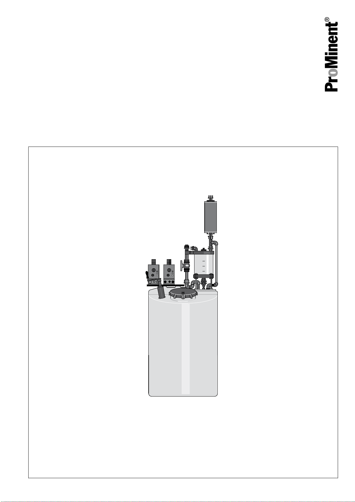
Hydrazine metering systems
DULCODOS® Hydrazin
EN
Please carefully read these operating instructions before use. · Do not discard.
The operator shall be liable for any damage caused by installation or operating errors.
The latest version of the operating instructions are available on our homepage.
Original operating instructions (2006/42/EC)Part no. 986548 BA DD 036 08/18 EN
Page 2
Supplemental directives
Supplementary information
Fig. 1: Please read!
Read the following supplementary information in its entirety! You will ben‐
efit more from using the operating instructions should you already know
this information.
The following are highlighted separately in the document:
n Enumerated lists
Instructions
Information
This provides important information relating to the cor‐
rect operation of the unit or is intended to make your
work easier.
Safety information
Safety information is identified by pictograms - see "Safety Chapter".
Notes for the system operator
This document includes notes and quotes from German guidelines relating
to the system operator's scope of responsibility. This information does not
discharge the operator from his responsibility as an operator and is
intended only to remind him or make him aware of specific problem areas.
This information does not lay claim to being complete, nor applicable to
every country and every type of application, nor to being unconditionally
up-to-date.
2
Page 3

Table of contents
Table of contents
List of other applicable documents.................................................. 4
1
2 Type list with performance data....................................................... 5
3 About the product............................................................................ 6
4 Safety chapter................................................................................. 7
5 Storage, transport, unpacking....................................................... 11
6 Overview of equipment and control elements............................... 12
7 Functional description.................................................................... 13
8 Assembly....................................................................................... 14
9 Installation..................................................................................... 15
9.1 Installation, hydraulic............................................................. 15
9.2 Installation, electrical............................................................. 17
10 Adjustment..................................................................................... 18
Start up.......................................................................................... 19
11
12 Operation....................................................................................... 23
13 Maintenance.................................................................................. 25
14 Repair and troubleshooting........................................................... 27
15 Decommissioning and disposal..................................................... 28
16 Technical data............................................................................... 30
16.1 Technical data for the complete system.............................. 30
16.2 Materials and properties of the components....................... 31
17 Spare parts and accessories......................................................... 33
17.1 Spare parts.......................................................................... 33
17.2 Accessories......................................................................... 34
18 Appendix........................................................................................ 35
18.1 Dimension sheets................................................................ 35
18.2 EC Declaration of Conformity.............................................. 36
18.3 Declaration of Decontamination.......................................... 36
18.4 Acceptance test certificate.................................................. 37
18.5 Technical data for hydrazine / levoxine 15%....................... 38
3
Page 4

List of other applicable documents
1 List of other applicable documents
Dependent on your order, you will find the
following applicable documents in the
appendix to these operating instructions:
Title
Operating Instructions Beta® b BT4b and BT5b Solenoid Metering Pump
4
Page 5

2 Type list with performance data
Hydrazine metering systems DUL‐
CODOS® Hydrazin
Pump data
Type list with performance data
Dosing tank volume Metering pump
capacity
l l / h bar l / h
140 7.1 7.0 approx. 17 913018
250 11.0 7.0 approx. 32 913019
Back pressure, max. Transfer pump capacity Order no.
5
Page 6

About the product
3 About the product
The Hydrazine metering systems DULCODOS® Hydrazin are used for the
manual batching and automatic metering of diluted hydrazine solution.
They are closed hydrazine systems. Hydrazine is used as an oxygen
binding agent to prevent corrosion in hot water and steam generators.
6
Page 7
4 Safety chapter
Safety chapter
Labelling of safety information
Signal word Meaning
WARNING Denotes a possibly hazardous situation. If this is disre‐
CAUTION Denotes a possibly hazardous situation. If this is disre‐
Warning symbols denoting different types
of danger
The following signal words are used in these operating instructions to
denote different levels of danger:
garded, your life is at risk or you are at risk of severe inju‐
ries.
garded, it could result in slight or minor injuries or material
damage.
The following warning symbols are used in these operating instructions to
denote different types of danger:
Warning signs Type of danger
Warning – toxic substances.
Warning – danger zone.
Intended use
Qualification of personnel
Task Qualification
Storage, transport, unpacking Technical personnel
Assembly, installation of the hydraulic system Technical personnel
n The systems are only intended for the batching of hydrazine-water
solutions and for metering as corrosion inhibitors in water-steam cir‐
cuits or steam and condensate systems.
n The systems may only be started up after correct installation and com‐
missioning - in accordance with the technical data and specifications
detailed in these operating instructions and the operating instructions
for the individual components.
n All other uses or a modification of the system are only permitted with
the written authorisation of ProMinent, Heidelberg.
n The systems are not intended for operation in areas at risk from explo‐
sion.
n The systems are not intended for the metering of gaseous or solid
media or other liquid media.
n The systems are not intended for use outdoors.
n You are obliged to observe the information contained in the operating
instructions at the different phases of the unit’s service life (such as
assembly, installation etc.).
n Make sure that the metering systems are only operated by trained and
authorised personnel, see table.
Electrical installation Technical personnel, electrical technician recommended
Start up Technical experts or authorised technical personnel
Operation Instructed person
Maintenance Technical personnel and instructed personnel, depending
on task
7
Page 8

Safety chapter
Task Qualification
Repair Technical personnel
Troubleshooting Technical personnel
Decommissioning / Disposal Technical personnel
Technical personnel
A qualified employee is deemed to be a person who is able to assess the
tasks assigned to him and recognise possible dangers based on his/her
technical training, knowledge and experience, as well as knowledge of
pertinent regulations.
Technical expert
A technical expert is deemed to be a person who is able to assess the
tasks assigned to him and recognise possible dangers based on his/her
technical training and experience, as well as knowledge of applicable reg‐
ulations.
Instructed person
An instructed person is deemed to be a person who has been instructed
and, if required, trained in the tasks assigned to him/her and possible dan‐
gers that could result from improper behaviour, as well as having been
instructed in the required protective equipment and protective measures.
Sound pressure level
Safety information
Electrical technician
An electrical technician is able to complete work on electrical systems and
recognise and avoid possible dangers independently based on his tech‐
nical training and experience as well as knowledge of pertinent standards
and regulations.
The electrical technician must be specifically trained for the working envi‐
ronment in which he is employed and be conversant with the relevant
standards and regulations.
The electrical technician must comply with the provisions of the applicable
statutory directives on accident prevention.
The sound pressure level is < 70 dB (A)
According to DIN EN ISO 3743-1
Operator’s obligations!
The operator of the system has a duty to operate the
system in such a way that there is no risk from the
system. It is the responsibility of the operator to provide
appropriate personnel and ensure the correct qualifica‐
tion of personnel.
8
Page 9
Safety chapter
WARNING!
Danger from hazardous substances!
Possible consequence: Fatal or very serious injuries.
Please ensure when handling hazardous substances
that you have read the latest safety data sheets provided
by the manufacture of the hazardous substance. The
actions required are described in the safety data sheet.
Check the safety data sheet regularly and replace, if
necessary, as the hazard potential of a substance can
be re-evaluated at any time based on new findings.
The system operator is responsible for ensuring that
these safety data sheets are available and that they are
kept up to date, as well as for producing an associated
hazard assessment for the workstations affected.
CAUTION!
Danger due to insufficient information
Disregarding the operating instructions for the metering
pump and other possible units can lead to potentially
hazardous situations.
Please observe the operating instructions for the
metering pumps and any other units which may be fitted.
Safety equipment
Information in the event of an emergency
Personal protective equipment
Health hazards
First aid instructions
NOTICE!
Warning of illegal operation
Observe the regulations that apply where the device is
installed.
The safety equipment available and instructions for testing are contained
in the "Start up" chapter.
Disconnect the system from the mains/power supply in the event of an
electrical emergency or if the solution leaks from the system during
pumping.
Refer to the material safety data sheet for hydrazine / levoxine in the event
of any accidents with hydrazine / levoxine.
Refer to the safety data sheet for hydrazine / levoxine.
- refer to the material safety data sheet for hydrazine / levoxine.
Note for the system operator
Keywords when searching for the necessary regulations:
n Hydrazine systems
n Hydrazine
n Storage
n Hazardous substances
n Personal protective equipment
n Water protection
n Air protection
9
Page 10

Safety chapter
Labelling
The operator must classify and label all storage tanks according to the
concentration of hydrazine contained in them.
10
Page 11
5 Storage, transport, unpacking
Safety information for hydrazine
WARNING!
Danger from hazardous substances!
Possible consequence: Fatal or very serious injuries.
Please ensure when handling hazardous substances
that you have read the latest safety data sheets provided
by the manufacture of the hazardous substance. The
actions required are described in the safety data sheet.
Check the safety data sheet regularly and replace, if
necessary, as the hazard potential of a substance can
be re-evaluated at any time based on new findings.
The system operator is responsible for ensuring that
these safety data sheets are available and that they are
kept up to date, as well as for producing an associated
hazard assessment for the workstations affected.
WARNING!
Only return metering pumps for repair in a cleaned state
and with a flushed liquid end - refer to "Decommis‐
sioning!
Only return metering pumps with a completed Decon‐
tamination Declaration form. The Decontamination Dec‐
laration constitutes an integral part of an inspection /
repair order. A unit can only be inspected or repaired
when a Declaration of Decontamination Form is sub‐
mitted that has been completed correctly and in full by
an authorised and qualified person on behalf of the
pump operator.
The "Decontamination Declaration Form" can be found
on our homepage.
Storage, transport, unpacking
NOTICE!
Danger of material damage
The device can be damaged by incorrect or improper
storage or transportation!
– The device should only be stored or transported in a
well packaged state - preferably in its original pack‐
aging.
–
The packaged unit should also only be stored or
transported in accordance with the stipulated
storage conditions.
– The packaged unit should be protected from mois‐
ture and the ingress of chemicals.
Ambient conditions
n Storage and transport temperature +5 ... +50 °C.
n Air humidity, max. 92% relative humidity, non-condensing.
11
Page 12
P_HYD_0020_SW
Overview of equipment and control elements
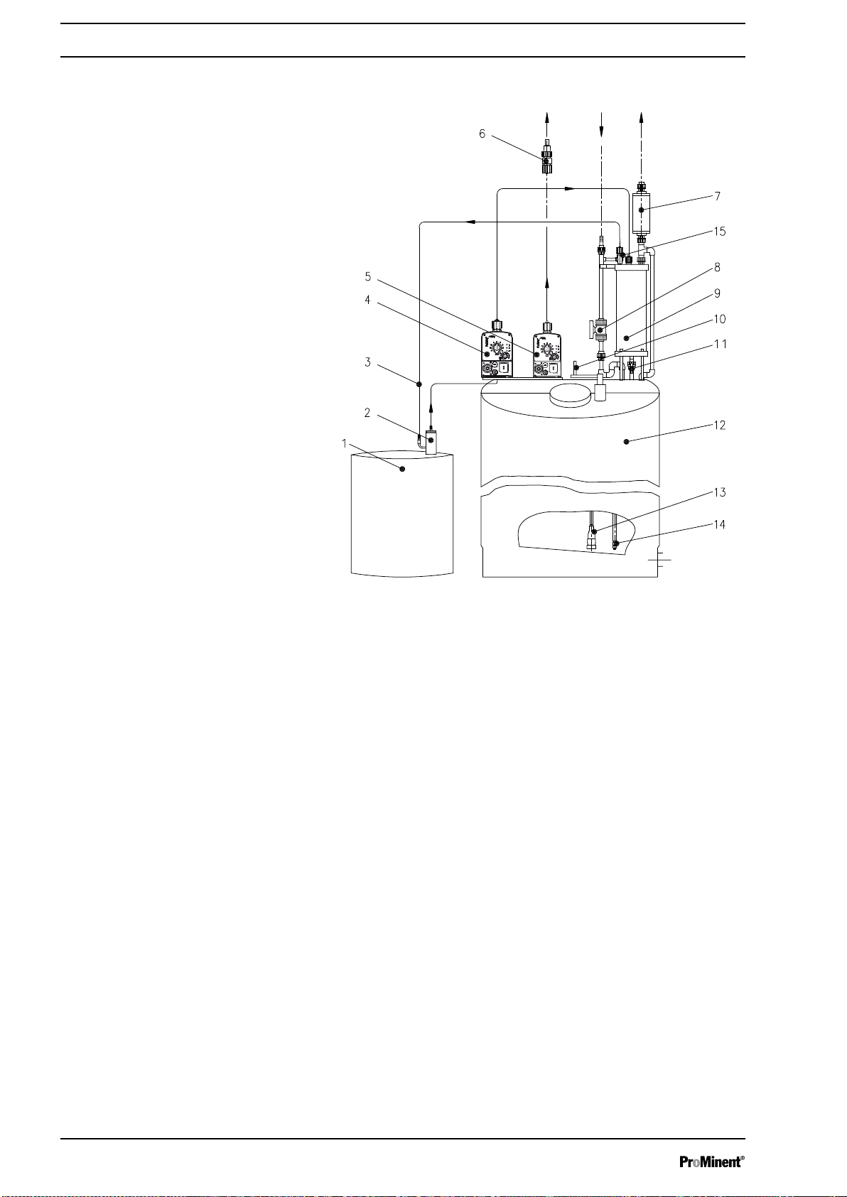
6 Overview of equipment and control elements
Fig. 2: Overview of equipment metering system DULCODOS® Hydrazin
1 Storage tank with connector for coupling (accessories)
2 Coupling (accessories)
3 Vapour recovery line
4 Decanting pump (with control elements)
5 Metering pump for metering (with control elements
6 Injection valve
7 Vent filter
8 Stopcock 1 (for diluting water)
9 Metering container with level switch
10 Manual stirrer
11 Stopcock 2 (for hydrazine in metering container)
12 Chemical feed container with sprinkler
13 Suction assembly
14 Chemical feed container level switch
Not shown in
figure
Not shown in
figure
Collecting pan
Flushing equipment (accessories. connector for cou‐
pling)
12
Page 13

7 Functional description
The hydrazine solution is batched semi-automatically. The operating per‐
sonnel use the manual stirrer to create a homogeneous solution.
The metering pump meters the hydrazine solution via the injection valve
into the desired pipework. Metering can be precisely controlled via the
external control of the metering pump.
The vapour recovery line permits transfer within a closed system. The dis‐
charge air filter breaks down escaping hydrazine into ammonia. A bleed
line transports the ammonia out of the building.
The operator of the system must use a collecting pan or other suitable
measure to prevent hydrazine from discharging into the environment in the
event of a leak. The operator of the system may wish to attach a leak
probe etc. to the collecting pan to trigger an alarm.
Functional description
WARNING!
Danger from hazardous substances!
Possible consequence: Fatal or very serious injuries.
Please ensure when handling hazardous substances
that you have read the latest safety data sheets provided
by the manufacture of the hazardous substance. The
actions required are described in the safety data sheet.
Check the safety data sheet regularly and replace, if
necessary, as the hazard potential of a substance can
be re-evaluated at any time based on new findings.
The system operator is responsible for ensuring that
these safety data sheets are available and that they are
kept up to date, as well as for producing an associated
hazard assessment for the workstations affected.
13
Page 14

Assembly
8 Assembly
WARNING!
Danger from hazardous substances!
Possible consequence: Fatal or very serious injuries.
Please ensure when handling hazardous substances
that you have read the latest safety data sheets provided
by the manufacture of the hazardous substance. The
actions required are described in the safety data sheet.
Check the safety data sheet regularly and replace, if
necessary, as the hazard potential of a substance can
be re-evaluated at any time based on new findings.
The system operator is responsible for ensuring that
these safety data sheets are available and that they are
kept up to date, as well as for producing an associated
hazard assessment for the workstations affected.
Requirements for the installation site
The operator must provide the following at the installation site:
1 - Water connection with eye bath
1 - Water connection for deionised water (diluting water and rinsing
water)
2 - Mains power sockets for both metering pumps
1 - Leak-tight pan provided by the customer around the installation loca‐
tion and suitable for hydrazine or a collecting pan - see "Accessories"
chapter.
The following parameters serve as a guideline for the operator, although
other or supplementary measures may be needed depending on the
installation site:
n The installation location must be in a closed room with good ventila‐
tion.
n The site of the hydrazine system must be protected against sun, frost-
proof and well ventilated.
n The exhaust air must be able to rise upwards and outside or into a
bleed line.
n It must be possible to fit the flushing adapter.
n A horizontal, smooth and stable surface must be available for the
installation.
n It must be possible to fasten the system to prevent if from toppling
over.
n The operator must ensure that the system cannot be damaged
mechanically from internal traffic
plate.
n The operator must ensure that the system cannot be flooded at the
installation site.
etc. If necessary, mount a guard
14
Page 15

9 Installation
P_HYD_0021_SW
A B
Installation, hydraulic
9.1
Installation
Fig. 3: A. Screw parts together, B. make the internal piping connections
1. Assemble the supplied parts of the hydrazine dosing system and
screw together with the connectors of the chemical feed container to
form a tight fit - see
1. - Decanting pump
2. - Metering pump.
3. - Diluting water feed
4. - Activate carbon filter. Also secure using the metal angle!
5. - Hand crank
2. Make the internal piping connections - see
1. - Decanting pump suction line for the storage tank. Use hose
clips as necessary!
2. - Vapour recovery line from the dosing tank for the storage tank.
Use hose clips as necessary!
3. - Decanting line from the decanting pump to the metering con‐
tainer
4. - Suction line of the metering pump
Fig. 3 A.
Fig. 3 B.
15
Page 16

P_HYD_0022_SW
Installation
Fig. 4: Make external piping connections
3. Make the external piping connections - see
WARNING!
Warning of toxic hydrazine
The system can overflow in the event of backflow
from the main line.
– Install an injection valve or vacuum breaker.
WARNING!
Warning of toxic hydrazine vapour
Hydrazine vapour can escape in the event of a
problem with the active carbon filter at the installa‐
tion site.
– Lay an exhaust line leading outdoors from the
active carbon filter.
–
The exit point of the exhaust air line is to be
aligned so that it is not directly accessible and
so that foreign bodies cannot penetrate
inside.
– The exhaust air line must be subsequently
accessible for inspection.
Fig. 4.
1. - Metering line from the metering pump to the installed injection
valve
2. - Diluting water line of the diluting water supply to the water line
3. - Exhaust line leading outdoors from the active carbon filter
4. - Flushing water line for the flushing adapter to the water supply
(not illustrated)
16
Page 17

9.2 Installation, electrical
P_HYD_0026_SW
4 3 4 1 2
A B
Installation
4. Install the flushing adapter.
n Mount the flushing adapter to the wall.
n Connect the flushing adapter to the diluting water stopcock.
Fig. 5: Undertake the electrical installation for (A) the transfer pump and (B) metering pump
Make the electrical cabling connections - see Fig. 5.
1. - Insert the plug of the suction lance level switch (chemical feed
container) in the "Level switch connector" at the metering
pump.
2. - Plug the signal cable from a control into the "External oper‐
ating modes connection" at the metering pump.
3. - Insert the plug of the decanting vessel level switch in the
"Level switch connector" at the decanting pump.
4. - Only for collecting pan with leakage probe: Undertake the
electrical installation for the leakage probe so that an alarm is
triggered in the event of a leak.
5. - Install an emergency cut-off switch for both pumps.
6. - Connect both mains cables to the mains outlets.
17
Page 18

1
2
P_HYD_0027_SW
Adjustment
10 Adjustment
1. Set the transfer pump to 100% stroke length - while it is running and to 100% stroke rate (multifunctional switch).
2. Adapt the “metering pump” using the stroke length and the stroke
rate (multifunctional switch) to the conditions of your process - see
also "Operating instructions for metering pumps Beta BT4 and BT5".
Fig. 6: Pump adjustment
1 Stroke length adjustment button
2 Multifunctional switch
18
Page 19

11 Start up
Safety information
Start up
WARNING!
Danger from hazardous substances!
Possible consequence: Fatal or very serious injuries.
Please ensure when handling hazardous substances
that you have read the latest safety data sheets provided
by the manufacture of the hazardous substance. The
actions required are described in the safety data sheet.
Check the safety data sheet regularly and replace, if
necessary, as the hazard potential of a substance can
be re-evaluated at any time based on new findings.
The system operator is responsible for ensuring that
these safety data sheets are available and that they are
kept up to date, as well as for producing an associated
hazard assessment for the workstations affected.
WARNING!
Hydrazine can escape
Hydrazine can escape if the system is not handled cor‐
rectly.
– Only allow technical experts or authorised technical
personnel to start up the system!
– The accepting technical expert or authorised tech‐
nical personnel must verify acceptance of the hydra‐
zine metering system for the operator by means of
the "Acceptance test certificate" - see appendix for
copy.
List of safety equipment
Safety equipment test
The following parameters serve as a guideline for the operator, although
other or supplementary measures may be needed depending on the
installation site:
n Coupling for storage tank (e.g. Micro-Matic coupling) and flushing
adapter
n Vapour recovery line
n Active carbon filter with exhaust air line to be provided on site
n Tank cover with seal
n Labels on tank cover
n Injection valve or vacuum breaker (the latter to be provided on site)
n Collecting pan (to be provided on site), leak sensor recommended
n Guard plate (optional, to be provided on site)
n Emergency stop switch (to be provided on site)
Flush the system before undertaking the test.
Most of the safety equipment is tested in
on page 19
n Tank cover seal
n Labels on tank cover
n Active carbon filter
and
Ä Chapter 11 ‘Start up’ on page 19
Test: Is the seal intact and firmly screwed to the storage tank lid?
Test: Is the label still attached, up-to-date and easily legible?
Test: Not possible. Replace every 6 months.
Ä Chapter 11 ‘Start up’
. In addition:
19
Page 20

Start up
Checking for cleanliness
n Injection valve or vacuum breaker
Test: Loosen the discharge line on the metering pump and observe if
liquid is forced back.
n Collecting pan (to be provided on site)
Test: Fill with water and check for water tightness. Then remove the
water again.
n Guard plate (optional)
Test: Check to ensure it is still sufficiently sturdy.
n Emergency stop switch (to be provided on site)
Test: Press the emergency stop switch while the pump is in operation.
The pump must come to a standstill.
CAUTION!
Warning catalytic decomposition
Dirt can trigger catalytic decomposition with hydrazine.
– Check that the system is free of dirt and contamina‐
tion.
Check that the system is free of dirt and contamination.
Perform initial commissioning
Checking for leak-tightness
The following parameters serve as a
guideline for the operator, although other
or supplementary measures may be
needed depending on the installation site:
Initial commissioning together with the acceptance test is under‐
taken in Germany in accordance with the principles set out in
"Admission of closed decanting and metering systems for aqueous
solutions of hydrazine", according to BBG-907/1999.
1. If hydrazine has already been present in the system, flush it out see chapter "Decommissioning".
2. Carefully meter the resulting solution into the application.
3. Close the active carbon filter with a blanking cap.
4. Close the screw lid on the dosing tank.
5. Open the stopcock on the metering vessel.
6. Close the stopcock for diluting water.
7. Remove the threaded connector on the diluting water connection.
8. Screw the T-piece with manometer and compressed air connector
on to the diluting water connector of the hydrazine metering system.
9. Adjust the pressure reduction valve of the compressed air supply to
a test pressure of 80 mbar.
10. Open the diluting water stopcock and fill the complete hydrazine
metering system with compressed air until the manometer displays
a constant 80 mbar. Close the stopcock on the testing fitting. The
test duration is 5 minutes.
11. Check the closed screw lid of the storage tank of the hydrazine
metering system as well as the stirrer and its storage tank opening
for leaks (leak spray).
12. Check the fastening points for the foot valve support pipe and the
level switch as well as the openings for the suction lines and the
level switch cable for leaks.
13. Check the flange of the storage tank flange for the metering vessel,
the fixing bolts, all openings for the diluting water lines, the aerating
and bleed lines and the filling line (with stopcock) for leak-tightness.
14. Check the complete top part of the storage tank and the fastening
points of the fastening plate of the metering and transfer pumps for
leak-tightness.
20
Page 21

Start up
15. Check the storage tank and storage tank base for cracks or other
damage and leak-tightness.
16. Check all adhesion points for leak-tightness, all pipework, threaded
connectors and pipe connections on the metering vessel.
17. Check all threaded connectors for leak-tightness:
n on the stopcocks
n on the stopcock
n on the diluting water line
n on the active carbon filter
n on the metering vessel, as well as the float plugs of the level
switches
18. Check the housing of the active carbon filter for leak-tightness.
19. Check the vapour recovery line for leak-tightness at the connectors,
the metering tank and the suction line of the transfer pump as well
as the test tank connection.
20. The pressure must not have fallen by more than
duration of 5 minutes has expired.
21. Remove the blind cap on the active carbon filter and hook up the
exhaust air line again.
10 mbar after a test
Operational test using diluting water
The following parameters serve as a
guideline for the operator, although other
or supplementary measures may be
needed depending on the installation site:
1. Close the bottom stopcock on the metering vessel and connect the
diluting water line.
2. Fill the dosing tank through the diluting water line up to the max‐
imum level (140 l or 250 l marking) depending on the size of the
tank.
3. Close the stopcock on the diluting water line.
4. Completely fill the test tank (empty hydrazine storage tank) with
rinsing water, e.g. condensate or deionised water.
5. Check the operation of the transfer pump and also check that the
transfer pump is switched off by the level switch in the metering
vessel:
Switch on the transfer pump and fill the metering vessel until the
level switch is triggered and the transfer pump stops. Simultane‐
ously check the parts, such as the transfer pump, suction line, the
line to the metering vessel and the metering vessel itself for leaktightness. Finally close the stopcock once more.
6. Functional test of the metering pump for metering: Switch on the
metering pump and bleed the liquid end (see "Operating instructions
for solenoid metering pump Beta® BT4 and BT5"). While doing this,
check the metering pump, metering line and the injection valve and
its fastening point for leaks. Finally switch off the metering pump.
7. Replace the test tank with a storage tank, once the Micro-Matic cou‐
pling has been removed. When doing so and prior to placing the
coupling on the storage tank, ensure that the suction line and the
vapour recovery line are fastened to the coupling with hose clips.
Ensure the line connectors are securely seated and check for leaks.
8. After commissioning the hydrazine metering system, carry out one
more complete visual inspection to ensure ultimate safety.
Acceptance test certificate
The accepting personnel (technical expert or authorised technical
personnel) must verify acceptance of the hydrazine metering system
for the operator by means of the "Acceptance test certificate" (see
appendix for "Acceptance test certificate" template).
21
Page 22

Start up
The hydrazine metering system can be released for operation if all of the
points detailed in the acceptance test are fulfilled during initial commis‐
sioning.
22
Page 23

12 Operation
Batching hydrazine solution
Operation
WARNING!
Danger from hazardous substances!
Possible consequence: Fatal or very serious injuries.
Please ensure when handling hazardous substances
that you have read the latest safety data sheets provided
by the manufacture of the hazardous substance. The
actions required are described in the safety data sheet.
Check the safety data sheet regularly and replace, if
necessary, as the hazard potential of a substance can
be re-evaluated at any time based on new findings.
The system operator is responsible for ensuring that
these safety data sheets are available and that they are
kept up to date, as well as for producing an associated
hazard assessment for the workstations affected.
WARNING!
Hydrazine solution can escape
If hydrazine solution is batched without supervision,
hydrazine solution can be forced out of the system under
pressure.
– As batching is done in manual mode, it must be
monitored from start to finish.
WARNING!
Hydrazine vapours can escape
Hydrazine vapours will escape if the lid of the dosing
tank is open.
– The lid of the dosing tank must not and may not be
opened.
1. Open the stopcock 1 (2) for diluting water and initially fill the dosing
tank a third full.
2. Using the multifunctional switch (1), switch the transfer pump from
"stop" to "100", so that hydrazine is pumped from the storage tank
into the metering vessel (3). When the maximum liquid level is
reached, the level switch turns the transfer pump off.
3. Using the multifunctional switch (2), switch the transfer pump from
"100" to "stop" so that the transfer pump does not meter unwanted
hydrazine as soon as the level switch drops when emptying the
metering vessel (3).
4. Simultaneously open the stopcock 2 (5) at the bottom of the
metering storage tank and stopcock 1 (2) for diluting water – hydra‐
zine flows into the dosing tank and, at the same time, a mist of
diluting water condenses evaporated hydrazine.
5. Close both stopcocks as soon as the maximum filling level has been
reached (marking 140 l or 250 l depending on the size of tank).
6. Use the manual stirrer (4) to stir for approximately 15 seconds to
ensure a homogeneous solution.
The metering pump can now meter the hydrazine solution into
ð
the application.
Adjusting the capacity
The capacity can be adjusted using both the stroke rate (multifunctional
switch) and the stroke length (see the attached "Operating instructions for
solenoid metering pump Beta®
23
BT4 and BT5").
Page 24

Operation
Replacing the storage tank
WARNING!
Danger from hazardous substances!
Possible consequence: Fatal or very serious injuries.
Please ensure when handling hazardous substances
that you have read the latest safety data sheets provided
by the manufacture of the hazardous substance. The
actions required are described in the safety data sheet.
Check the safety data sheet regularly and replace, if
necessary, as the hazard potential of a substance can
be re-evaluated at any time based on new findings.
The system operator is responsible for ensuring that
these safety data sheets are available and that they are
kept up to date, as well as for producing an associated
hazard assessment for the workstations affected.
WARNING!
Droplets of hydrazine could be released
When replacing the storage tank, it is possible that drop‐
lets of hydrazine are spilt.
– Wear tightly fitting safety glasses and suitable safety
gloves when working on the system!
WARNING!
Hydrazine can escape
Hydrazine can escape if the storage tank is not handled
correctly.
– Return any empty re-usable containers to the sup‐
plier.
–
Dispose of any unrinsed single-use drums correctly.
As soon as the storage tank is empty, replace it with a full storage tank.
Replacement of the storage tank is described for a Micro-Matic coupling:
1. Unscrew the protective cap from the new storage tank.
2. Push up the release handle on the Micro-Matic coupling on the old
storage tank.
3. Unscrew the Micro-Matic coupling in an anticlockwise direction from
the valve on the connecting piece.
4. Place the Micro-Matic coupling with the 3 cams on the valve on the
connecting piece and turn clockwise until it engages and stops.
5. Press the handle of the Micro-Matic coupling downwards so that the
spring steel bracket on the coupling engages. The valve is now
opened.
6. Seal the suction connection on the empty storage tank with the pro‐
tective cap.
7. Return the empty storage tank to the supplier or a waste manage‐
ment firm.
24
Page 25

13 Maintenance
Safety information
Maintenance
WARNING!
It is mandatory that you read the safety information and
specifications in the "Storage, Transport and Unpacking"
chapter prior to shipping the pump.
WARNING!
Danger from hazardous substances!
Possible consequence: Fatal or very serious injuries.
Please ensure when handling hazardous substances
that you have read the latest safety data sheets provided
by the manufacture of the hazardous substance. The
actions required are described in the safety data sheet.
Check the safety data sheet regularly and replace, if
necessary, as the hazard potential of a substance can
be re-evaluated at any time based on new findings.
The system operator is responsible for ensuring that
these safety data sheets are available and that they are
kept up to date, as well as for producing an associated
hazard assessment for the workstations affected.
WARNING!
Hydrazine can escape
Hydrazine may escape when carrying out the work listed
below.
– Wear tightly fitting safety glasses and suitable safety
gloves when working on the system!
WARNING!
Hydrazine vapours can escape
Hydrazine vapours will escape if the dosing tank or the
storage tank needs to be opened.
– Refer to the material safety data sheet provided by
the chemical supplier.
Maintenance work
Interval Maintenance work Personnel
annually Check the hydrazine metering system to ensure it is in good working order. Technical personnel
Check the hydrazine metering system for leak-tightness - see chapter
"Start up".
Technical personnel
Replace the diaphragms of the metering and transfer pumps. Technical personnel
Perform an acceptance test for the hydrazine metering system. This must
be verified by the "Acceptance test certificate" - see "Appendix".
daily Check the hydrazine metering system to ensure that it is in good working
order (visual inspection).
Check the hydrazine metering system for leaks (visual inspection). Instructed personnel
25
Technical personnel
Instructed personnel
Page 26

Maintenance
Interval Maintenance work Personnel
every 6 months Replace the active carbon filter - see section "Maintenance of active
carbon filter" below.
every two years Replace the relief valve diaphragm - see operating instructions for the relief
valve.
Maintenance of the active carbon filter
WARNING!
Hydrazine can escape
Hydrazine may escape when carrying out the work listed
below.
– Therefore always flush the system - see chapter
"Decommissioning and disposal"!
Refit the new active carbon filter to the metal bracket
–
so that it cannot break off!
– Properly dispose of the active carbon filter!
1. Flush the hydrazine metering system - see chapter "Decommis‐
sioning and disposal".
2. Dismantle the used active carbon filter.
3. Fit the new active carbon filter.
4. Refit the new active carbon filter to the metal bracket so that it
cannot break off.
5. Re-connect the exhaust air line to the active carbon filter
6. Properly dispose of the used active carbon filter.
Technical personnel
Technical personnel
26
Page 27

14 Repair and troubleshooting
WARNING!
It is mandatory that you read the safety information and
specifications in the "Storage, Transport and Unpacking"
chapter prior to shipping the pump.
WARNING!
Danger from hazardous substances!
Possible consequence: Fatal or very serious injuries.
Please ensure when handling hazardous substances
that you have read the latest safety data sheets provided
by the manufacture of the hazardous substance. The
actions required are described in the safety data sheet.
Check the safety data sheet regularly and replace, if
necessary, as the hazard potential of a substance can
be re-evaluated at any time based on new findings.
The system operator is responsible for ensuring that
these safety data sheets are available and that they are
kept up to date, as well as for producing an associated
hazard assessment for the workstations affected.
Repair and troubleshooting
WARNING!
Hydrazine / levoxine can escape
Hydrazine / levoxine may escape when carrying out the
work listed below.
– Therefore always flush the system - see chapter
"Decommissioning and disposal"!
–
Take the safety measures recommended in the
material safety data sheets when working on the
system.
– Refer to the material safety data sheet provided by
the chemical supplier if the dosing tank or the
storage tank needs to be opened.
– Only use the correct spare parts.
– On completion of the work, check the system for
leak-tightness and record the results.
If necessary refer to the operating instructions for the metering pumps and
the relief valve when troubleshooting.
27
Page 28

Decommissioning and disposal
15 Decommissioning and disposal
Decommissioning
WARNING!
Danger from hazardous substances!
Possible consequence: Fatal or very serious injuries.
Please ensure when handling hazardous substances
that you have read the latest safety data sheets provided
by the manufacture of the hazardous substance. The
actions required are described in the safety data sheet.
Check the safety data sheet regularly and replace, if
necessary, as the hazard potential of a substance can
be re-evaluated at any time based on new findings.
The system operator is responsible for ensuring that
these safety data sheets are available and that they are
kept up to date, as well as for producing an associated
hazard assessment for the workstations affected.
WARNING!
Toxic hydrazine / levoxine can escape
The hydrazine metering system still contains residue of
hydrazine / levoxine.
– Flush the system with diluting water - see "Flushing
the system".
– Take appropriate protective measures, referring to
the material safety data sheet provided by the chem‐
ical supplier.
Flushing the system
Fig. 7: Flushing the system
1 Stopcock (rinsing water)
2 Pressure reducer (max. 2 bar)
3 Flushing adapter
4 Micro-Matic coupling
5 Hydrazine system
1. First remove the Micro-Matic coupling from the vessel and place it
on the flushing adapter.
2. Completely fill the metering vessel with water at least twice and
drain into the dosing tank through the ball valve.
3. Carefully meter the resulting solution into the process.
The transfer pump could be removed after
28
this.
Page 29

Disposal
Decommissioning and disposal
WARNING!
Hydrazine / levoxine can escape
The hydrazine metering system contains at the very
least the residue of hydrazine / levoxine.
– Flush the system with diluting water - see
Ä ‘Decommissioning’ on page 28
– Correctly dispose of the diluting water.
– Wear protective equipment, as outlined in the mate‐
rial safety data sheet provided by the chemical sup‐
plier.
– Refer to the material safety data sheet provided by
the chemical supplier if the dosing tank or the
storage tank needs to be opened.
CAUTION!
Warning about non-compliance with disposal regulations
– Note the pertinent regulations currently applicable in
your country.
–
Also refer to the operating instructions for the
metering pumps and relief valves.
.
29
Page 30

Technical data
16 Technical data
Safety information
CAUTION!
Warning about operation with insufficient technical data
Incomplete technical data could result in problems
occurring during operation of the hydrazine metering
system!
– Also observe the operating instructions for "Solenoid
metering pumps Beta® BT4 and BT5".
16.1 Technical data for the complete system
Dimensions and weights, metering system
with 140 l
Data Value Unit
Width 520 mm
Height 1,650 mm
Depth 600 mm
Dimensions and weights, metering system
with 250 l
Ambient conditions
Net weight, approx. 23 kg
Gross weight, approx. 160 kg
Diluting water connector, hose nozzle DN10
Max. operating pressure of diluting water 3 bar
Data Value Unit
Width: 650 mm
Height: 2,120 mm
Depth 650 mm
Net weight, approx.: 35 kg
Gross weight, approx.: 280 kg
Diluting water connector, hose nozzle: DN10
Max. operating pressure of diluting water: 3 bar
Data Value Unit
Storage and transport temperature: +5 ... +50 °C
Pump data
Ambient temperature during operation: +5 ... +40 °C
Feed chemical temperature: +5 ... +35 °C
Maximum air humidity*: 92 % relative
humidity
* non-condensing
30
Page 31

Technical data
Dosing tank volume Metering pump
l l / h bar l / h
140 7.1 7.0 approx. 17 913018
250 11.0 7.0 approx. 32 913019
Degree of protection
Sound pressure level
16.2
Hydrazine metering system, 140 l
Materials and properties of the components
capacity
Back pressure, max. Transfer pump capacity Order no.
Protection against contact and moisture:
IP 65 in accordance with IEC 529, EN 60529, DIN VDE 0470 Part 1
The sound pressure level is < 70 dB (A)
According to DIN EN ISO 3743-1
1 - Metering pump Beta®
at max. back pressure 7.0 bar. You can find more detailed information
in your operating instructions.
1 - Metering pump Beta® BT5b0420NPE0000UA004100, used as a
transfer pump, pump capacity 17.1 l/h
You can find more detailed information in your operating instructions.
1 - PE dosing tank, volume 140 l, with litre scale and closable screw lid,
"gas-tight version"
1 - Complete PVC suction assembly, "gas-tight version" (installed in the
dosing tank)
1 - Electrical level switch with support pipe (installed in the dosing tank)
1 - PVC manual stirrer, "gas-tight version"
1 - Fastening plate for mounting the metering pumps on the storage tank
1 - Metering vessel, transparent PVC, volume 2 l, with electrical level
switch for switching off the transfer pump on reaching a high level, as
well as the necessary hoses
1 - Active carbon filter
1 - PVC ball valve, d16, NW10 with pipework
1 - 1.4571 stainless steel injection valve , connector 8 mm-1/2“
1 - Metering line PTFE , 11 bar, 12 x 9 mm
1 - Micro-Matic coupling with flushing adapter (optional)
1 - Suction line PVC 12 x 9 mm, 1.5 m
1 - Vapour recovery line PVC 8 x 5 mm, 1.5 m
BT4b0708NPE0000UA004100, capacity 7.1 l/h
at max. back pressure 4 bar.
31
Page 32

Technical data
Hydrazine metering system, 250 l
1 - Metering pump Beta® BT5b0713NPE0000UA004100, capacity
11.0 l/h at max. back pressure 7.0 bar. You can find more detailed
information in your operating instructions.
1 - Metering pump Beta®
BT5b0232NPE0000UA004100, used as a
transfer pump, pump capacity 32.0 l/h at max. back pressure 2 bar.
You can find more detailed information in your operating instructions.
1 - PE dosing tank, volume 250 l, with litre scale and closable screw lid,
"gas-tight version"
1 - Complete PVC suction assembly, "gas-tight version" (installed in the
dosing tank)
1 - Electrical level switch with support pipe (installed in the dosing tank)
1 - PVC manual stirrer, "gas-tight version"
1 - Fastening plate for mounting the metering pumps on the storage tank
1 - Metering vessel, transparent PVC, volume 5 l, with electrical level
switch for switching off the transfer pump on reaching a high level, as
well as the necessary hoses
1 - Active carbon filter
1 - PVC ball valve, d16, NW10 with pipework
1 - 1.4571 stainless steel injection valve , connector 12 mm-1/2“
1 - Metering line PTFE, 11 bar 8x5 mm, 5 m
1 - Micro-Matic coupling with flushing adapter (optional)
1 - Suction line PVC 12 x 9 mm, 1.5 m
1 - Vapour recovery line PVC 8 x 5 mm, 1.5 m
Dosing tank, complete
Injection valve
Coupling for the storage tank (e.g. MicroMatic)
PE dosing tank, gas-tight screw lid, gas-tight PVC manual stirrer, trans‐
parent PVC metering vessel with drain tap, connectors for filling line,
vapour recovery line, aeration and bleeding, with active carbon filter 1.0 l,
diluting water line with stopcock, all connectors PVC gas-tight, water line
connector R 1/2".
1.4571 stainless steel injection valve, with support insert for connection to
a stainless steel line:
n 8 mm - for
140 l system
n 12 mm - for 250 l system
The injection valve is equipped with a 1/2" nipple for fixing to the point of
injection.
The coupling has hose nozzles for the transfer pump and the vapour
recovery line.
32
Page 33

17 Spare parts and accessories
Spare parts and accessories
17.1
Metering system 140 l (part no. 913018)
Tab. 1: For metering pump Beta® BT4b0708NPT0000UA004100:
Description Order no.
Beta® BT4b0708NPT0000UA004100 without bleed valve
Dosing head with suction/pressure connectors, without diaphragm, without connector kit 1034458
Connector kit 8x5 1035641
Diaphragms 46.0x21.5 1000248
Discharge valve, complete 9.2-2 PCE 1021690
Suction valve, complete 9.2-2 PCE 1021677
Tab. 2: For transfer pump Beta® BT5b0420NPT0000UA004100:
Description Order no.
Beta® BT5b0420NPT0000UA004100 without bleed valve
Dosing head with suction/pressure connectors, without diaphragm, without connector kit 1034460
Connector kit 12x9 1035642
Metering diaphragm 70.0x33.5 1000250
Spare parts
1036869
1036868
Discharge valve, complete 9.2-2 PCE 1021690
Suction valve, complete 9.2-2 PCE 1021677
Tab. 3: Miscellaneous parts:
Description Order no.
Active carbon filter (including 500202) 809819
Metering vessel, 2 l 809860
Manual stirrer, 140 l 809803
Micro-Matic coupling 1003964
33
Page 34

Spare parts and accessories
Metering system 250 l (part no. 913019)
Tab. 4: For metering pump Beta® BT5b0713NPT0000UA004100:
Description Order no.
Beta® BT5b0713NPT0000UA004100 without bleed valve
Dosing head with suction/pressure connectors, without diaphragm, without connector kit 1034461
Connector kit 8x5 1035642
Metering diaphragm 55.0x26.0 1000249
Discharge valve, complete 9.2-2 PCE 1021690
Suction valve, complete 9.2-2 PCE 1021677
1037109
Tab. 5: For transfer pump Beta® BT5b0232NPT0000UA004100:
Description Order no.
Beta® BT5b0232NPT0000UA004100 without bleed valve
Dosing head with suction/pressure connectors, without diaphragm, without connector kit 1034461
Connector kit 12x9 1035642
Metering diaphragm 91.0x46.0 1000251
Discharge valve, complete 9.2-2 PCE 1021690
Suction valve, complete 9.2-2 PCE 1021677
1037108
Tab. 6: Miscellaneous parts:
Description Order no.
Active carbon filter (including 500202) 809819
Metering vessel, 5 l 809861
Manual stirrer, 250 l 809813
Micro-Matic coupling 1003964
17.2 Accessories
Tab. 7: For all metering systems
Description Order no.
Stainless steel extraction kit 1003964
Collecting pan 200 l with design certification and galvanised grid on request
Collecting pan 1000 l with design certification and galvanized grid on request
34
Page 35

18 Appendix
P_HYD_0023_SW
P_HYD_0024_SW
Appendix
18.1
DULCODOS® Hydrazin 140 l
Dimension sheets
DULCODOS® Hydrazin 250 l
Fig. 8: Dimensional drawing Hydrazin 140 l (dimensions in mm)
Fig. 9: Dimensional drawing Hydrazin 250 l (dimensions in mm)
35
Page 36

Appendix
18.2 EC Declaration of Conformity
In accordance with DIRECTIVE 2006/42/EC OF THE EUROPEAN PAR‐
LIAMENT AND OF THE COUNCIL, Appendix II 1.A.
We,
n ProMinent GmbH
n Im Schuhmachergewann 5 - 11
n D - 69123 Heidelberg, Germany,
hereby declare that the product specified in the following complies with the
relevant basic health and safety rules of the EC Directive, on the basis of
its functional concept and design and in the version marketed by us.
Tab. 8: Excerpt from the Declaration of Conformity
Designation of the product:
Product type: Hydrazine metering system
Material numbers: 913018
Serial number: see nameplate on the unit
DULCODOS® Hydrazin
913019
Relevant EC directives: EC Machinery Directive (2006/42/EC)
EC EMC Directive (2014/30/EC)
Compliance with the protection targets of the Low Voltage Directive 2014/35/EU
according to Appendix I, No. 1.5.1 of the Machinery Directive 2006/42/EC
Harmonised standards applied, in
particular:
Date: 09.04.2018
EN ISO 12100:2010
EN 60204-1:2006/A1:2009
EN 809:1998+-a1:2009+AC:2010
EN 14123-1:2015
You can download the Declaration of Conformity at www.prominent.com.
18.3 Declaration of Decontamination
You will find the current Declaration of Decontamination to download on
the manufacturer's homepage.
36
Page 37

18.4 Acceptance test certificate
DULCODOS® Hydrazin
ACCEPTANCE TEST CERTIFICATE
Serial number
Project number / customer order
Custom
(Tick where applicable)
Initial commissioning in accordance with BBG-907, updated version 1999
Cyclic testing in accordance with BBG-907, updated version 1999
Layout and installation of the hydrazine metering system corresponds to BBG-907 /1999?
yes
no
Does the installation of the hydrazine metering system correspond to the current state of the art?
yes
no
Does the labelling of the hydrazine metering system correspond to BGI-567 and M 011?
yes
no
Does the function of the hydrazine metering system correspond to BGI-907 /1999?
yes
no Does the leak test for the hydrazine metering system correspond to BGI-907 /1999?
yes
no
Is the operator of the hydrazine metering system in possession of a set of operating instructions?
yes
no
Can the hydrazine metering system be started?
yes
no
Can the hydrazine metering system remain in normal operation?
yes
no
Remarks:
Operator:
Date:
Plac
Signature operator:
Signature technical expert:
Original for operator / carbon copy for ProMinent Dosiertechnik GmbH
Notice: 10068/001 created:
Bannas
tested:
Bannas
changed: Page 1 of 1
Document: 82 05-401 00 07-TB A 1D-01 (AbnahmeDrkoll deu Hvdrazin) Date: 2010-06-02 Time: 10:24
ProMinent Dosiertechnik GmbH, P.O. Box 10 17 60, D-69007 Heidel berg - Germany
Appendix
37
Page 38

Appendix
18.5 Technical data for hydrazine / levoxine 15%
WARNING!
Danger from hazardous substances!
Possible consequence: Fatal or very serious injuries.
Please ensure when handling hazardous substances
that you have read the latest safety data sheets provided
by the manufacture of the hazardous substance. The
actions required are described in the safety data sheet.
Check the safety data sheet regularly and replace, if
necessary, as the hazard potential of a substance can
be re-evaluated at any time based on new findings.
The system operator is responsible for ensuring that
these safety data sheets are available and that they are
kept up to date, as well as for producing an associated
hazard assessment for the workstations affected.
38
Page 39

39
Page 40

ProMinent GmbH
Im Schuhmachergewann 5-11
69123 Heidelberg
Germany
Telephone: +49 6221 842-0
Fax: +49 6221 842-419
Email: info@prominent.com
Internet: www.prominent.com
986548, 2, en_GB
© 2007
 Loading...