

Page 1
Operating instructions
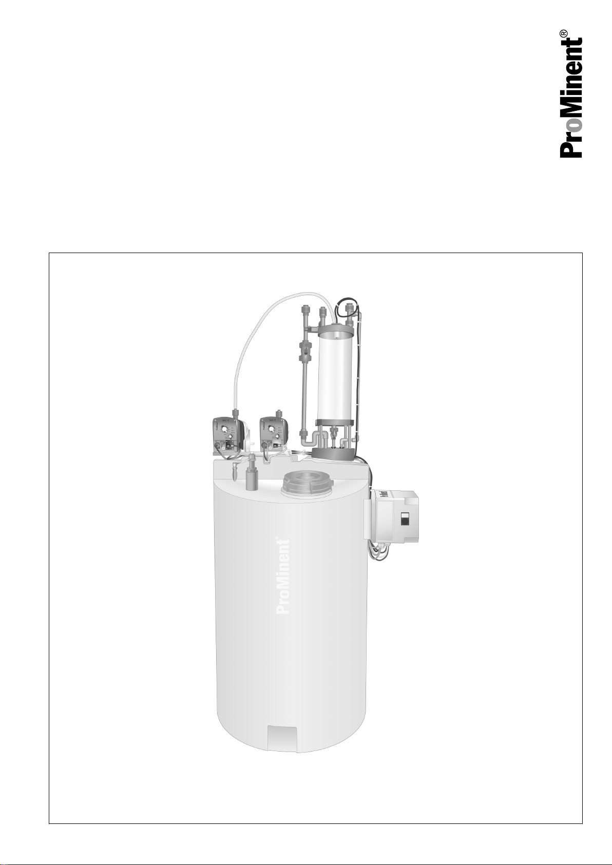
Ammonia water dilution and metering system
DULCODOS® Ammonia
EN
Please carefully read these operating instructions before use. · Do not discard.
The operator shall be liable for any damage caused by installation or operating errors.
The latest version of the operating instructions are available on our homepage.
Original operating instructions (2006/42/EC)981962 BA DD 037 02/19 EN
Page 2
Supplemental directives
Supplementary information
Read the following supplementary information in its entirety! You
will benefit more from using the operating instructions should you
already know this information.
The following are highlighted separately in the document:
Fig. 1: Please read!
Validity
Notes for the system operator
n Enumerated lists
Instructions
Information
This provides important information relating to the
correct operation of the unit or is intended to make
your work easier.
Safety information
Safety information is identified by pictograms - see "Safety
Chapter".
These operating instructions conform to current EU regulations
applicable at the time of publication.
This document includes notes and quotes from German guidelines
relating to the system operator's scope of responsibility. This infor‐
mation does not discharge the operator from his responsibility as
an operator and is intended only to remind him or make him aware
of specific problem areas. This information does not lay claim to
being complete, nor applicable to every country and every type of
application, nor to being unconditionally up-to-date.
2
Page 3

Table of contents
Table of contents
List of other applicable documents....................................... 4
1
2 Type list with performance data............................................ 5
3 About the product.................................................................. 6
4 Safety chapter....................................................................... 7
5 Storage, transport, unpacking............................................. 12
6 Overview of equipment and control elements..................... 14
7 Functional description......................................................... 16
8 Assembly............................................................................ 17
9 Installation........................................................................... 19
9.1 Installation, hydraulic.................................................. 19
9.2 Installation, electrical.................................................. 21
10 Start up............................................................................... 23
10.1 Checking for leak-tightness...................................... 23
10.2 Setting....................................................................... 24
10.3 Functional test with dilution water............................. 25
11 Operation............................................................................ 27
Maintenance....................................................................... 33
12
13 Repair................................................................................. 35
14 Troubleshooting.................................................................. 37
15 Decommissioning and disposal.......................................... 38
15.1 Decommissioning..................................................... 38
15.2 Disposal.................................................................... 38
16 Technical data..................................................................... 40
16.1 Technical data for the complete system................... 40
16.2 Materials and properties of the components............. 42
17 Spare parts and accessories.............................................. 44
17.1 Spare parts............................................................... 44
17.2 Accessories.............................................................. 45
18 Dimensional drawings......................................................... 46
19 Declaration of Conformity for Machinery............................. 48
20 Index................................................................................... 49
3
Page 4

List of other applicable documents
1 List of other applicable documents
Dependent on your order, you will find
the following applicable documents in
the appendix to these operating
instructions:
Title
Operating Instructions for Solenoid Metering Pump Beta® b BT4b
and BT5b
Wiring diagram for the terminal box for ammonia water with up to
25% w/w:
Document no. 82_05-401_00_05-44
4
Page 5

Type list with performance data
2 Type list with performance data
Ammonia water metering systems
DULCODOS® Ammonia
Tab. 1
Dosing tank
volume, nom‐
inal
l l l l / h bar l / h
130 120 2 7 4 approx. 15 1039192
250 250 5 7 2 approx. 36 1039193
Dosing tank
volume,
usable
Metering
vessel, usable
Metering
pump
Capacity
Transfer
pump
Delivery
height
Transfer
pump
Pump
capacity
Order no.
5
Page 6

About the product
3 About the product
The metering system DULCODOS® Ammonia is used for the gastight transfer and dilution of ammonia water to common metering
concentrations and for automatic metering into the feed water.
Ammonia (NH3), or diluted in water: Ammonium hydroxide
(NH4OH) is used for the alkalising and binding of free carbonic acid
in boiler water and condensate.
Common stock solutions: from 5% to 25% NH3 (% w/w) (ammonia
water).
The usual metering concentration is 0.1% ... 2.5% NH3 (% w/w).
6
Page 7
4 Safety chapter
Safety chapter
Labelling of safety information
Warning symbols denoting different
types of danger
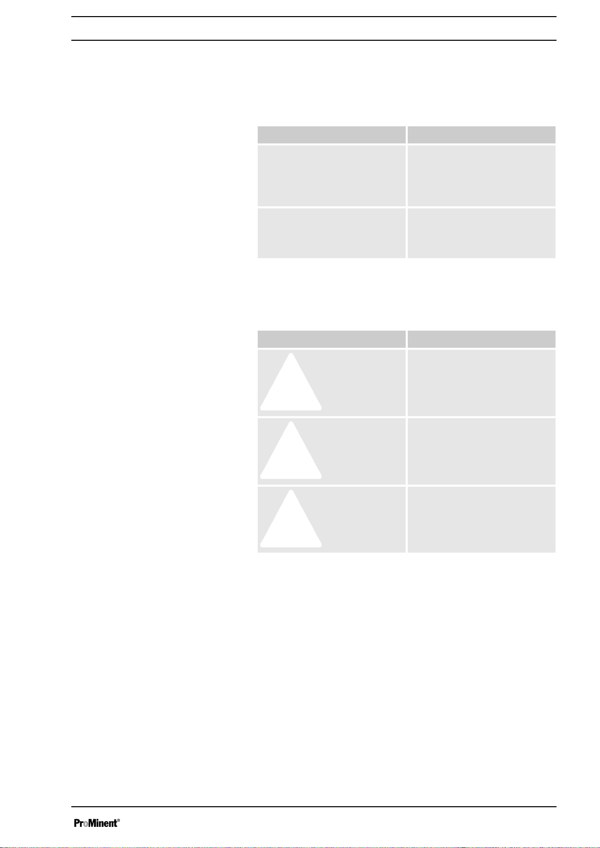
The following signal words are used in these operating instructions
to denote different levels of danger:
Signal word Meaning
WARNING Denotes a possibly hazardous
situation. If this is disregarded,
you are in a life-threatening sit‐
uation and this can result in
serious injuries.
CAUTION Denotes a possibly hazardous
situation. If this is disregarded,
it could result in slight or minor
injuries or material damage.
The following warning symbols are used in these operating instruc‐
tions to denote different types of danger:
Warning symbol Type of danger
Warning of a dangerous area.
Intended use
Warning of hazardous electrical
voltage.
Warning of a risk of explosion
n The metering system DULCODOS® Ammonia is only intended
for batching ammonia water in common concentrations of up to
max. 25% into standard solutions of 0.1% to max. 2.5% and
metering this into water-steam circuits or into steam and con‐
densate systems.
n The metering system DULCODOS®
used after correct installation and start up - according to the
technical data and specifications outlined in these operating
instructions and the operating instructions for the individual
components.
n The metering system DULCODOS® Ammonia is not intended
for other uses.
n In the event of a modification, the operator or the contractor he
has appointed becomes the manufacturer of the modified
system in accordance with EC Regulation 2006/42/EC – with
the corresponding obligations.
Ammonia may only be
7
Page 8

Safety chapter
n The metering system DULCODOS® Ammonia is not intended
for metering other chemicals, such as sodium hydroxide solu‐
tion.
n The metering system DULCODOS® Ammonia is not intended
for the metering of gaseous or solid media or other liquid
media.
n You are obliged to observe the information contained in the
operating instructions at the different phases of the unit’s
service life (such as assembly, installation etc.).
n These operating instructions contain a summary of the impor‐
tant functions of each of the components used.
The technical information and operating instructions for the
components used form an integral part of the entire operating
instructions and must be observed.
n Make sure that the metering systems are only operated by
trained and authorised personnel, see table.
Qualification of personnel
Task Qualification
Storage, transport, unpacking Technical personnel
Assembly, installation of the
Technical personnel
hydraulic system
Electrical installation Technical personnel, electrical
technician recommended
Start up Authorised technical personnel
Operation Instructed person
Maintenance Technical personnel
Repair Authorised skilled personnel
proven to have been trained by
ProMinent
Troubleshooting Technical personnel
Decommissioning / Disposal Technical personnel
Electrician
Electricians are deemed to be people, who are able to complete
work on electrical systems and recognise and avoid possible haz‐
ards independently based on his/her technical training and experi‐
ence, as well as knowledge of pertinent standards and regulations.
Electricians should be specifically trained for the working environ‐
ment in which the are employed and know the relevant standards
and regulations.
Electricians must comply with the provisions of the applicable stat‐
utory directives on accident prevention.
Instructed personnel
The instructed personnel have been instructed by the operator in a
training session about the tasks allocated to them and potential
hazards with incorrect and improper conduct.
Technical personnel
Technical personnel are deemed to be people, who are able to
complete the tasks allocated to them and recognise and avoid haz‐
ards independently based on his/her technical training and experi‐
ence, as well as knowledge of pertinent regulations.
8
Page 9
Safety information
Safety chapter
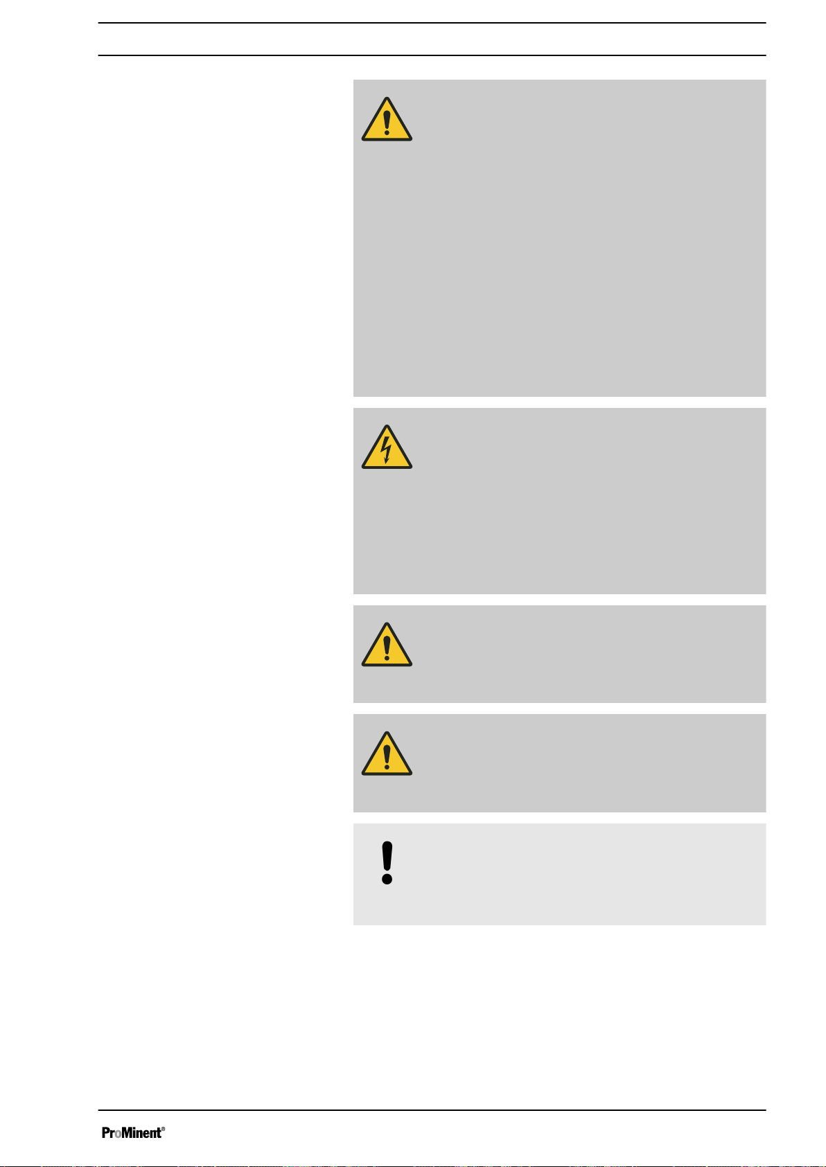
WARNING!
Danger from hazardous substances!
Possible consequence: Fatal or very serious inju‐
ries.
Please ensure when handling hazardous sub‐
stances that you have read the latest safety data
sheets provided by the manufacture of the haz‐
ardous substance. The actions required are
described in the safety data sheet. Check the
safety data sheet regularly and replace, if neces‐
sary, as the hazard potential of a substance can be
re-evaluated at any time based on new findings.
The system operator is responsible for ensuring
that these safety data sheets are available and that
they are kept up to date, as well as for producing
an associated hazard assessment for the worksta‐
tions affected.
WARNING!
Danger of electric shock
Mains voltage may be present inside the pump
housing and the switch cabinet.
– Immediately disconnect the system from the
mains power supply if the pump housing or
switch cabinet has been damaged. Only return
the pump to service after it has been repaired
by authorised personnel.
Potential danger from the system
CAUTION!
Please also observe the operating instructions for
the metering pump and any other units which may
be fitted.
CAUTION!
Do not climb onto the system or parts thereof - the
metering station cannot support the load, could
leak or topple over.
NOTICE!
Warning of illegal operation
Observe the regulations that apply where the
device is installed.
The following dangers could arise if incorrectly operated or mis‐
used:
Water pollution and damage to health
n Water pollution and damage to health due to escaping liquids.
n Damage to health from the inhalation of ammonia vapours.
n Dangerous reactions due to contact with other chemicals.
9
Page 10

Safety chapter
Take special precautions with storage and metering. The specific
potential danger and resulting hazards should be taken from the
current material safety data sheet for the substance used.
Danger of explosion
n Risk of explosion due to trapped ammonia-air mixtures.
A potentially explosive ammonia-air mixture (lower explosion limit
15.4 vol.%, upper explosion limit 33.6 vol.%) can form in the inte‐
rior of the metering vessel and also in the interior of the supply
drum via the liquid phase depending on the temperature and con‐
centration of the commercial ammonia water product.
The built-in level switch in the metering vessel is therefore
designed to be intrinsically safe “i” with an explosion-proof design.
Pay attention to any static charge when connecting or replacing a
supply drum!
Information in the event of an emer‐
gency
Health hazards
First aid instructions
Note for the system operator
Turn the Emergency Stop switch to “0” in the event of an emer‐
gency or if liquid escapes from the system during pumping.
Refer to the material safety data sheet for ammonia water supplied
by the chemical supplier in the event of any accidents with
ammonia water.
If ammonia water escapes, evacuate the room, put on protective
equipment, seal the leak and, if necessary, collect the escaped sol‐
ution and dispose of!
Refer to the material safety data sheet for ammonia water provided
by the chemical supplier.
Refer to the material safety data sheet for ammonia water provided
by the chemical supplier.
Keywords when searching for the necessary regulations:
n Ammonia water systems
n Ammonia water
n Storage
n Hazardous substances
n Personal protective equipment
n Water protection
n Air protection
n ...
The “GESTIS Substance Database” published by the IFA Institute
for Occupational Health and Safety of the German Social Accident
Insurance provides valuable information.
Emissions
Direct contact with ammonia water may occur when changing over
the supply drum and during maintenance work. Observe the
instructions.
Emissions of ammonia gas are not expected due to the gas-tight
design of the storage tanks and the downstream exhaust air
adsorber. This is the case providing the adsorber is regularly
changed.
10
Page 11

Sound pressure level
Safety chapter
Sound pressure level LpA < 70 dB according to EN 3746
Protective equipment
Warning labels
The system is provided with the following protection equipment,
which prevents large quantities of ammonia from escaping, or the
resulting ignition of an ammonia water-air mixture:
n The level switch in the metering vessel prevents overflowing.
n The system is designed so that the transfer from the storage
tank to the metering vessel is via a vapour recovery line.
n The aeration and venting of the system is through an active
carbon filter, which absorbs the escaping ammonia gas.
n The lid of the dosing tank protects the user from ammonia gas.
It needs to be secured by a seal when operating with ammonia.
n The level switches in the metering vessel and in the dosing
tank are designed to be explosion-proof and intrinsically safe “i”
with an appropriate explosion-proof intrinsically safe “i” switch
amplifier.
Further recommendations, the implementation of which is however
outside our area of responsibility:
n Place the dosing tank in a collecting pan.
Affix workplace labels in line with the current regulations.
They might look like this in accordance with the German regula‐
tions governing printing of the operating instructions:
Warning of caustic substances
Use eye protection
Use safety gloves
Ensure that the warning label is always fitted and legible.
11
Page 12
Storage, transport, unpacking
5 Storage, transport, unpacking
Safety information
WARNING!
Warning of hazardous ammonia
Ammonia can escape in the event of damage.
– Make sure that the metering system is free
–
WARNING!
Only return metering pumps for repair in a cleaned
state and with a flushed liquid end - refer to
"Decommissioning!
Only return metering pumps with a completed
Decontamination Declaration form. The Declara‐
tion of Decontamination constitutes an integral part
of an inspection/repair order. A unit can only be
inspected or repaired when a Declaration of
Decontamination Form is submitted that has been
completed correctly and in full by an authorised
and qualified person on behalf of the pump oper‐
ator.
The "Declaration of Decontamination” form can be
found at www.prominent.com.
from ammonia prior to storage or transport.
Carefully protect the metering system against
mechanical damage, so that no one can be
endangered by escaping caustic ammonia
during subsequent operation.
WARNING!
Danger of leakage
The device can be damaged or leak by incorrect or
improper storage or transportation!
– Only store or transport the unit in its original
packaging.
–
The packaged device should also only be
stored or transported in accordance with the
stipulated storage conditions.
– The packaged device should be protected from
moisture and the ingress of chemicals.
CAUTION!
Danger of material damage
The device is top-heavy as long as the dosing tank
is empty.
– Bear this in mind when transporting it.
12
Page 13

Storage, transport, unpacking
Ambient conditions
Parameter Value
Minimum storage and transport temperature: 0 °C
Maximum storage and transport temperature: +50 °C
Minimum ambient temperature during operation: 0 °C
Maximum ambient temperature during operation*
at up to 15% ammonia water:
at up to 20% ammonia water:
at up to 25% ammonia water:
35°C
30°C
25°C
Max. temperature of the dilution water: 20°C
Maximum air humidity**: 92% relative humidity
* The higher the starting concentration, the lower the temperature
needs to be.
** non-condensing
Do not allow to stand in direct sunlight.
13
Page 14
P_HYD_0011_SW.svg
Overview of equipment and control elements
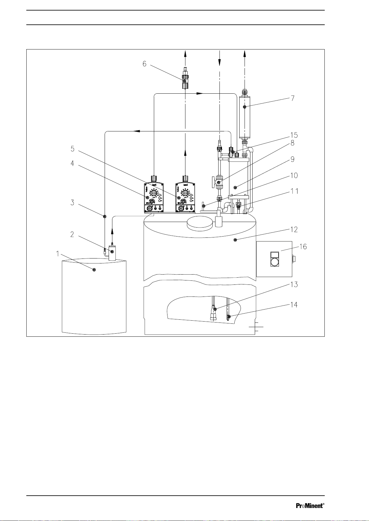
6 Overview of equipment and control elements
Fig. 2: Overview of equipment: metering system DULCODOS® Ammonia
1 Supply drum (not in the scope of
delivery)
2 Suction lance with gas recovery (acces‐
sory)
3 Vapour recovery line
4 Transfer pump (with control elements)
5 Metering pump (for metering; with con‐
trol elements)
6 Injection valve
7 Chemical vapour lock
8 Stopcock (dilution water)
9 Metering vessel with level switch
10 Manual stirrer
11 Stopcock (metering vessel drainage)
12 Dosing tank with sprinkler
13 Suction assembly
14 Dosing tank level switch
15 Stopcock (rinsing water metering vessel)
16 Switch cabinet - see also Fig. 3
Not shown Collecting pan (accessory)
14
Page 15
1
2
P_HYD_0029_SW
Overview of equipment and control elements
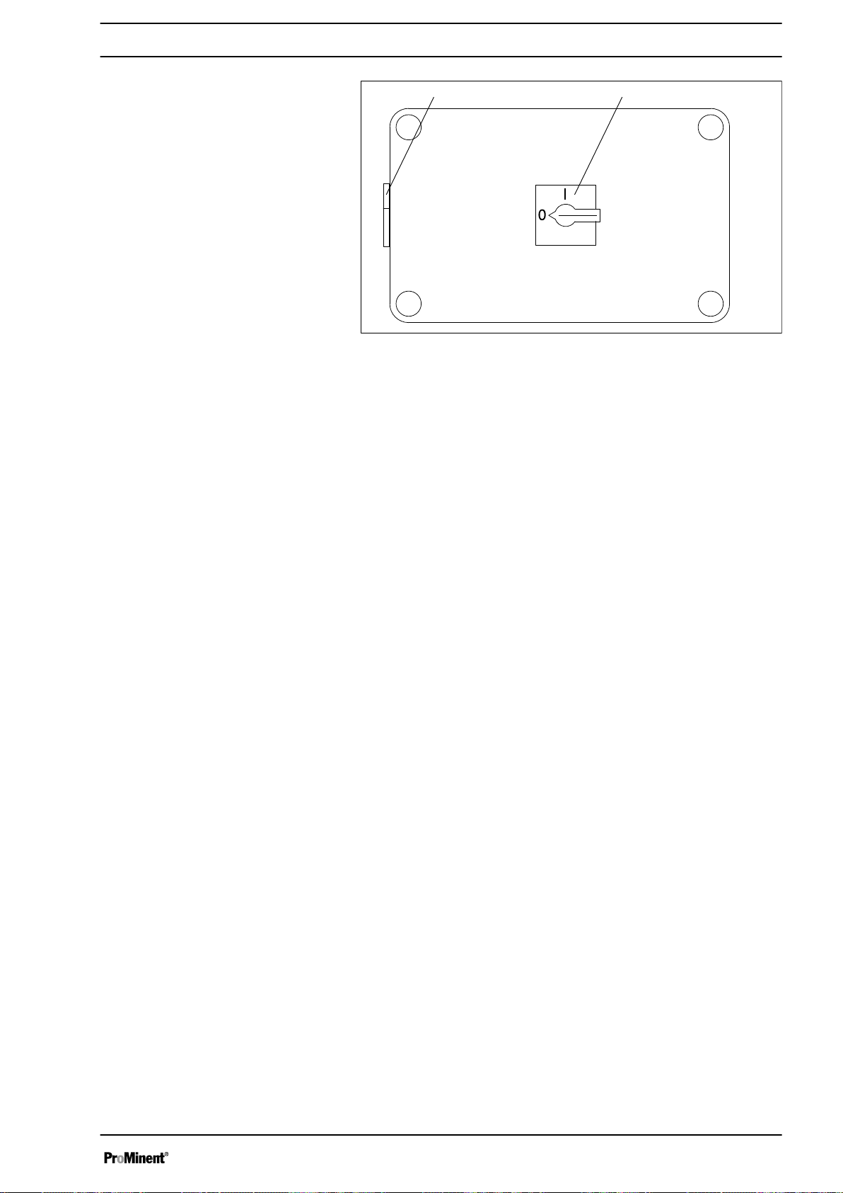
Fig. 3: Switch cabinet control elements(on the side of the system)
1 Main switch with Emergency Stop function
2 “Start filling metering vessel” key
15
Page 16

Functional description
7 Functional description
The DULCODOS® Ammonia system is used for the gas-tight
transfer and dilution to usual metering concentrations and then
automatic metering into the feed water.
The dosing tank (12) needs to be filled with de-ionised water to
batch a diluted usable ammonia water solution. The transfer pump
(4) semi-automatically fills concentrated ammonia water solution
(max. 25%) from the supply drum (1) into a metering vessel (9). An
appropriate amount of this concentrated solution from this metering
vessel needs to be left in the dosing tank to obtain a final concen‐
tration of between 0.1% ... 2.5%.
The manual stirrer (10) mixes the solution until it is homogeneous.
A chemical vapour lock (adsorber) (7) is fitted on the metering
vessel to prevent ammonia vapours from escaping into the envi‐
ronment.
The metering pump (5) meters the ready-to-use ammonia solution
from the dosing tank at the corresponding point of injection (6).
Metering can be provided on-demand using external control of the
metering pump.
Optional fault indicating relays on the pumps can report faults on a
control panel.
16
Page 17

8 Assembly
Safety information
Assembly
WARNING!
Warning of hazardous ammonia
Ammonia can escape if the system is not handled
correctly.
– Store and transport the metering system in its
original packaging. Take special precautions to
ensure that the metering system is protected
against mechanical damage
Select a suitable installation site for the
–
ammonia water metering system.
WARNING!
Danger of severe eye injuries
Immediately rinse the eyes in the event of
ammonia coming into contact with them.
– Provide an eye shower (with water connection)
directly adjacent to the installation site.
Requirements for the installation site
WARNING!
Warning of explosive atmospheres
An explosive air-ammonia mixture can form with
high concentrations of ammonia water – particu‐
larly above 15% w/w – or also at high ambient tem‐
peratures (at over 30 °C above 10% w/w).
– Note the current regulations and technical reg‐
ulations dealing with ammonia and ensure ade‐
quate ventilation.
CAUTION!
Observe the material safety data sheet
Observe the current material safety data sheet for
ammonia water.
The following must be available at the installation site:
n Water connector with eye shower (refer to the material safety
data sheet)
n Water connector for deionised water (dilution water and rinsing
water). Properties - refer to "Technical data" chapter
n Prevent the installation site from unauthorised access.
n Mains connection 230 V / 50 Hz for the system.
n An appropriate exhaust air duct for an exhaust air line from the
chemical vapour lock.
n Recommendation: There needs to be a gas detector fitted
n brick or masonry, leak-tight tray provided on site around the
installation site or a collecting pan with ribs on the inside (on
request).
n A horizontal, level and stable surface must be available for the
installation.
17
Page 18

Assembly
n The system must be secured against possible damage from
people, objects and mobile equipment, such as fork-lifts or
pallet trucks.
n There needs to be 1 metre clearance around the system for
maintenance purposes.
n The installation site must have continuous effective ventilation.
n Depending on the actual conditions on site, the installation site
for the system and supply drum may need to fulfil other
requirements in line with the applicable regulations and tech‐
nical rules!
n Take appropriate measures if any of the following chemicals
are stored at the installation site: phosphorus oxides, acids,
oxygen bottles, hydrogen sulphide (H2S), strong oxidising
agents, hydrogen peroxide (H2O2), zinc, nitric acid, ethylene
oxide, strong alkalis, chlorates, mercury, silver or hydrogen
bromide (HBr).
18
Page 19

9 Installation
P_HYD_0012_SW
1
2
3
Installation, hydraulic
9.1
Installation
WARNING!
Warning of hazardous ammonia solution
Ammonia solution will escape if the metering line
comes off or tears.
– Only fit lines of sufficient strength.
Note the resistance of the line material.
–
– Prevent the metering line from coming off
caused by back pressure or tearing. You may
wish to install a relief valve.
WARNING!
Warning of hazardous ammonia solution
Liquid from the application could press back
through the metering pump.
– Use an injection valve or vacuum breaker.
Personnel:
1.
Technical personnel
n
Screw together the units supplied for the metering system
DULCODOS® Ammonia as shown - see A:
1. - Chemical vapour lock
2. - Fastening bracket. Use it to screw the chemical vapour
lock to the metering vessel.
3. - Hand crank
19
Page 20

P_HYD_0033_SW
2
3
1
5
4
f
d
Installation
2. Make the internal piping connections - see B:
1. - “Transfer pump” (f) suction line to the suction lance for
the storage tank. Use hose clips!
2. - Vapour recovery line from the metering vessel to the
suction lance for the storage tank. Use hose clips!
3. Make the external pipe connections - see
Fig. 4:
1. - “Metering pump” (d) metering line to the installed injec‐
tion valve
2. - De-ionised water feed connector to fill the dosing tank
3. - Chemical vapour lock exhaust air line to the respective
exhaust air duct
20
Page 21

P_HYD_0013_SW_2
f
d
Installation
Fig. 4: External pipe connections
Note for the operator
An explosive atmosphere can form in the supply
drum with concentrations of over 15% w/w and/or
high ambient and media temperatures. If a spark
jumps as the suction lance is approaching the
open opening of the supply drum, it could cause
this atmosphere to explode.
Therefore take appropriate measures, such as the
following:
–
Use an earthing cable to ensure that the suc‐
tion lance and storage tank have the same
potential just before inserting the suction lance
into the storage tank.
–
Use suction lances with a level switch with
explosion protection for Zone 0.
–
Only connect the ammonia water to the system
in its original drum or in an electrically con‐
ducting vessel.
9.2 Installation, electrical
CAUTION!
The pump can start up again after a mains failure
– The operator needs to take appropriate meas‐
ures to rule out hazards that could arise during
this process when integrating the ammonia
metering system into a higher-level system.
21
Page 22

1
2
P_HYD_0029_SW
Installation
Personnel:
Electrician
n
1. Check whether the mains voltage is switched off!
2. Possibly: Connect a fault signalling alarm.
3. A remote demand can be connected to the metering pump
for metering the diluted ammonia solution into your process refer to “Operating instructions for solenoid metering pump
Beta b, BT4b and BT5b" and wiring diagram
"82_05-401_00_05-44".
4. Connect a mains cable from the switch cabinet (terminal strip
X0) to the mains voltage.
Fig. 5: Switch cabinet control elements(on the side of the system)
1 Main switch with Emergency Stop function
2 “Start filling metering vessel” key
22
Page 23

10 Start up
Safety information
10.1 Checking for leak-tightness
Materials required:
n Compressed air generator
n Leak spray
1. Fill the dosing tank using the dilution water tap.
2. Use a blanking cap to close the chemical vapour lock.
3. Open the bottom stopcock on the metering vessel.
4. Close the stopcock for dilution water.
5. Remove the threaded connector on the dilution water con‐
6. Screw the T-piece with manometer and compressed air con‐
7. Adjust the pressure reduction valve of the compressed air
8. Open the dilution water stopcock and fill the complete
9. Check the closed lid of the storage tank of the ammonia
10. Check the fastening points of the foot valve support pipe and
11. Check the tank flange for the metering vessel at the flange
12. Check the complete top part of the storage tank and the fas‐
13. Check the storage tank and storage tank base for cracks or
14. Check all adhesion points for leak-tightness on the complete
Start up
WARNING!
Hazardous ammonia water may escape
Hazardous ammonia water can escape from it if
the system is not operated correctly.
– Only allow authorised technical personnel to
start up the system!
nection.
nector onto the dilution water connector of the ammonia
water metering system.
supply to a test pressure of 80 mbar.
ammonia water metering system with compressed air until
the manometer displays a constant
cock on the test fitting. The test takes 5 minutes.
water metering system and the stirrer and its tank opening for
leaks (leak spray).
the level switch as well as the openings for the suction lines
and the level switch cable for leaks.
and the fixing bolts for leak-tightness as well as the openings
for the dilution water lines, the aerating and vent lines and
the filling line (with stopcock).
tening points of the fastening plate for the metering and
transfer pumps for leak-tightness.
other damage and leak-tightness.
pipework, on the threaded connectors and pipe connections,
on the metering vessel.
80 mbar. Close the stop‐
23
Page 24

A
P_HYD_0016_SW
f
d
Start up
15. Check all threaded connectors for leak-tightness:
n on the stopcocks
n on the dosing tank
n on the stopcock
n on the dilution water line
n on the chemical vapour lock
n on the metering vessel, as well as the float plug of the
level switch
16. Check that the housing of the chemical vapour lock is leaktight.
17. Check the vapour recovery line for leak-tightness at the con‐
nectors, the metering vessel and the suction line of the
transfer pump and on the test tank connection.
18. The pressure should not fall by more than
10 mbar after a
test time of 5 minutes.
19. The system can be started up if these conditions are met:
Remove the blanking cap on the chemical vapour lock again.
Re-connect the chemical vapour lock to the exhaust air duct.
20. Do not operate the system if the pressure falls by more than
10 mbar
!
Call ProMinent Service to rectify the leak.
10.2 Setting
1. Set the master switch on the terminal box to “I”.
2. If there is no voltage: Arrange for an electrical technician to
activate the automatic circuit breakers in the terminal box refer to the wiring diagram.
3. Set the “transfer pump” (f) to 100% stroke rate (multifunc‐
tional switch) and - while it is running - to 100% stroke length.
4. Use the stroke length and the stroke rate (multifunctional
switch) to adapt the “metering pump” (d) to the conditions of
your process - see also "Operating instructions for metering
pumps Beta BT4 and BT5".
Fig. 6: Operating elements
24
Page 25

1
2
P_HYD_0032_SW
Start up
Fig. 7: Adjusting the pump
1 Stroke length adjustment knob
2 Multifunctional switch
10.3 Functional test with dilution water
Note for the operator
An explosive atmosphere can form in the supply
drum with concentrations of over 15% w/w and/or
high ambient and media temperatures. If a spark
jumps as the suction lance is approaching the
open opening of the supply drum, it could cause
this atmosphere to explode.
Therefore take appropriate measures, such as the
following:
–
Use an earthing cable to ensure that the suc‐
tion lance and storage tank have the same
potential just before inserting the suction lance
into the storage tank.
–
Use suction lances with a level switch with
explosion protection for Zone 0.
–
Only connect the ammonia water to the system
in its original drum or in an electrically con‐
ducting vessel.
1. Close the bottom stopcock on the metering vessel and con‐
nect the dilution water line.
2. Fill the dosing tank through the dilution water line up to the
maximum level - 120 l or 250 l marking, dependent on the
tank size.
3. Close the stopcock on the dilution water line.
4. Completely fill the test tank (empty ammonia water supply
drum) with rinsing water, e.g. condensate or deionised water.
25
Page 26

Start up
5. Check the operation of the “transfer pump” and check that it
switches off via the level switch in the metering vessel: Start
up the “transfer pump” using the green key
[Start filling metering vessel]
(is the multifunctional switch
turned to “External”?) and fill the metering vessel until the
level switch is triggered and the “transfer pump” stops. At the
same time, check the parts, such as the “transfer pump”, suc‐
tion line, the line to the metering vessel and the metering
vessel itself for leak-tightness. Finally close the stopcock
once more.
6. Functional test of the “metering pump": Switch on the
“metering pump” at the multifunctional switch and bleed the
liquid end - see "Operating instructions for solenoid metering
pump Beta® BT4b and BT5b". Check the leak-tightness of
the “metering pump”, metering line and injection valve and
their threads. Finally switch off the “metering pump”.
7. Check whether the suction line and the vapour recovery line
are fastened to the suction lance with hose clips. Ensure the
line connectors are securely seated and check for leaks.
8. Only with concentrations above 15% w/w: Take appropriate
measures to prevent a spark jumping to ignite the ammoniaair atmosphere when attaching the suction lance to the
storage tank.
9. Replace the test tank with a storage tank.
10. After commissioning the ammonia water metering system,
carry out one more complete visual inspection to ensure its
final safety.
The ammonia water metering system can now be handed over for
operation.
26
Page 27

11 Operation
Batching ammonia water solution
Operation
WARNING!
Hazardous ammonia water solution may escape
If ammonia water solution is batched without
supervision, ammonia water solution can be
pressed out of the system.
– As batching is done in manual mode, the entire
process must be monitored from start to finish.
WARNING!
Hazardous ammonia vapours may escape.
Ammonia vapours will escape if the lid of the
dosing tank is open.
– The lid of the dosing tank must not and may
not be opened.
– The system must be shut down immediately
should the seal be missing on the lid and the
seal must be replaced by an authorised techni‐
cian.
CAUTION!
Only particle-free commercial ammonia water may
be used for batching.
Note for the operator
An explosive atmosphere can form in the supply
drum with concentrations of over 15% w/w and/or
high ambient and media temperatures. If a spark
jumps as the suction lance is approaching the
open opening of the supply drum, it could cause
this atmosphere to explode.
Therefore take appropriate measures, such as the
following:
–
Use an earthing cable to ensure that the suc‐
tion lance and storage tank have the same
potential just before inserting the suction lance
into the storage tank.
–
Use suction lances with a level switch with
explosion protection for Zone 0.
–
Only connect the ammonia water to the system
in its original drum or in an electrically con‐
ducting vessel.
Personal protective equipment
- always refer to the chemical supplier’s latest hazardous sub‐
stance data sheet and the latest regulations and materials safety
data sheets issued by the statutory accident prevention authorities.
27
Page 28

A
P_HYD_0016_SW
f
d
Operation
Eye protection:
Adequate eye protection must be worn. Wear goggles. Use a protective shield if the face
is also compromised.
Hand protection:
Use safety gloves. The glove material must be sufficiently impermeable and resistant to
the substance used.
Protective clothing:
Depending on the level of risk, wear a sufficiently long apron and boots or an appropriate
protective chemical suit.
Respiratory protection:
Wear respiratory protection in exceptional situations (e.g. in the event of accidental
release of the substance, exceeding of the occupational exposure limit): Gas filter K,
green colour code (Germany). Note the limits on time of wearing!
Use an isolation unit with concentrations above the application limit of filter equipment,
with oxygen contents bellow 17 vol% or in the event of unclear conditions!
Fig. 8: Operating elements
1 Multifunctional switch
2 Stopcock (dilution water)
3 Metering vessel
4 Manual stirrer
5 Stopcock (metering vessel drainage)
A Flushing connector - see next figure
Personnel:
Instructed personnel
n
1. Check whether the “metering pump” (d) is set to “Stop".
2. Check whether the “transfer pump” (f) is set to “100”.
3. Set the main switch to "I".
28
Page 29

6
2
5
P_HYD_0030_SW
Operation
Fig. 9: Detail A: Flushing connector and stopcocks
2 Stopcock (dilution water)
5 Stopcock (metering vessel drainage)
6 Stopcock (rinsing water metering vessel)
4. Open the dilution water stopcock (2) and fill the dosing tank
until half full.
WARNING!
The dosing tank needs to be filled with dilu‐
tion water to at least halfway – due to the
system’s internal explosion protection.
5. Open the bottom stopcock (5) on the metering vessel. Drain
any remains in the metering vessel through this stopcock into
the dosing tank.
The ammonia passes into the dosing tank through a pipe
ð
below the water level.
6. Start the “transfer pump” using the “Start filling metering
vessel” key.
It pumps ammonia water from the supply drum into the
ð
metering vessel (3).
The transfer pump level switch is triggered when the
maximum liquid level is reached**.
29
Page 30

Operation
7. Open the bottom stopcock (5) on the dilution water metering
vessel.
The ammonia passes into the dosing tank through a pipe
ð
below the water level.
Steps 5 and 6 can be repeated several
times if the required final concentration
needs several top-ups of the metering
vessel.
WARNING!
Note the following to ensure that the
ammonia concentration in the dosing
tank remains below the explosion limit:
– With starting solutions of 25% w/w
ammonia in water:
A maximum of 6 top-ups of the
metering vessel can be added to the
“120 l” dosing tank.
A maximum of 5 top-ups of the
metering vessel can be added to the
“250 l” dosing tank.
This ensures that the maximum per‐
mitted metering solution of 2.5% w/w
is not exceeded. Correspondingly
more top-ups are needed with lower
starting solutions.
8. Open the stopcock (6) – briefly flush the metering vessel with
the dilution water and re-close the stopcock (6).
9. Wait until the metering vessel has emptied and then close
the stopcock (5).
10. Open the stopcock (2) for dilution water and allow as much
water to flow into the dosing tank until the required concen‐
tration has been reached.
WARNING!
Hazardous ammonia water solution may
escape
Overfilling can cause hazardous ammonia
water solution to escape.
– Fill the dosing tank at most up to the top
marking (120 l or 250 l marking)
11. Use the manual stirrer (4) to stir for approximately 15 s to
obtain a homogeneous solution.
12. Set the multifunctional switch on the “metering pump” to the
required frequency or to “External”.
The “metering pump” can now meter the diluted ammonia
ð
water into the application.
30
Page 31

Tab. 2: **
Dosing tank
Volume, nominal
Dosing tank
Volume, usable
l l l
130 120 2
250 250 5
Operation
Metering vessel
Volume, usable
Adjusting the capacity
Replacing the storage tank
The capacity can be adjusted using both the stroke rate (multifunc‐
tional switch) and the stroke length - see the attached "Operating
instructions for solenoid metering pump Beta® BT4 and BT5".
WARNING!
Drops of hazardous ammonia water could be
released
Drops of ammonia water can spill when changing
the supply drum.
– Take appropriate protective measures as out‐
lined in the material safety data sheet when
working on the system.
WARNING!
Hazardous ammonia water can escape
Ammonia water can escape if the supply drum is
not handled correctly.
WARNING!
Warning of explosive atmospheres
An explosive air-ammonia mixture can form with
high concentrations of ammonia water – particu‐
larly above 15% w/w – or also at high ambient tem‐
peratures (at over 30 °C above 10% w/w).
– Note the current regulations and technical reg‐
ulations dealing with ammonia and ensure ade‐
quate ventilation.
31
Page 32

Operation
Note for the operator
An explosive atmosphere can form in the supply
drum with concentrations of over 15% w/w and/or
high ambient and media temperatures. If a spark
jumps as the suction lance is approaching the
open opening of the supply drum, it could cause
this atmosphere to explode.
Therefore take appropriate measures, such as the
following:
–
Use an earthing cable to ensure that the suc‐
tion lance and storage tank have the same
potential just before inserting the suction lance
into the storage tank.
–
Use suction lances with a level switch with
explosion protection for Zone 0.
–
Only connect the ammonia water to the system
in its original drum or in an electrically con‐
ducting vessel.
As soon as the supply drum is empty, replace it with a full
original supply drum.
32
Page 33

12 Maintenance
Safety information
Maintenance
WARNING!
It is mandatory that you read the safety information
and specifications in the "Storage, Transport and
Unpacking" chapter prior to shipping the pump.
WARNING!
Warning of explosive atmospheres
An explosive air-ammonia mixture can form with
high concentrations of ammonia water – particu‐
larly above 15% w/w – or also at high ambient tem‐
peratures (at over 30 °C above 10% w/w).
– Note the current regulations and technical reg‐
ulations dealing with ammonia and ensure ade‐
quate ventilation.
WARNING!
Hazardous ammonia vapours or ammonia water
may escape
Hazardous ammonia vapours will escape if the
dosing tank or the supply drum need to be opened.
– Wear suitable personal protective equipment -
see below.
Personal protective equipment
Eye protection:
Adequate eye protection must be worn. Wear goggles. Use a protective shield if the face
is also compromised.
Hand protection:
Use safety gloves. The glove material must be sufficiently impermeable and resistant to
the substance used.
Protective clothing:
Depending on the level of risk, wear a sufficiently long apron and boots or an appropriate
protective chemical suit.
Respiratory protection:
Wear respiratory protection in exceptional situations (e.g. in the event of accidental
release of the substance, exceeding of the occupational exposure limit): Gas filter K,
green colour code (Germany). Note the limits on time of wearing!
- always refer to the chemical supplier’s latest hazardous sub‐
stance data sheet and the latest regulations and materials safety
data sheets issued by the statutory accident prevention authorities.
Use an isolation unit with concentrations above the application limit of filter equipment,
with oxygen contents bellow 17 vol% or in the event of unclear conditions!
33
Page 34

Maintenance
Daily inspections
Inspection point Personnel
Check the surroundings of the system for the smell of ammonia. Technical personnel
Inspect the system for damage. Technical personnel
Check whether the seal on the dosing tank is damaged. Technical personnel
Stop the system and immediately have it repaired if one of these
points applies!
Maintenance work
Interval Maintenance work Personnel
monthly Check the ammonia water metering system to ensure it is in cor‐
rect working order.
Check whether the lines to the ammonia water metering system
and downstream of it are brittle or worn.
Visually check whether the electrical insulation of all cables to
the metering system and the supply lines are intact.
annually Replace the pump diaphragms - see "Operating instructions for
solenoid metering pump Beta BT4 and BT5".
quarterly Check the pump diaphragms for damage and replace if neces‐
sary - see "Operating instructions for solenoid metering pump
Beta BT4 and BT5".
every six months
Replace the chemical vapour lock - refer to
chemical vapour lock’ on page 34
.
Ä ‘Replacing the
Check the ammonia water metering system for leak-tightness
Ä Chapter 10.1 ‘Checking for leak-tightness’ on page 23
see
.
Record the result of the leak tightness test. Technical personnel
Replacing the chemical vapour lock
WARNING!
Hazardous ammonia water may escape
Ammonia water may escape when carrying out the
work listed below.
– Therefore always flush the system first, see
Ä Chapter 15 ‘Decommissioning and disposal’
on page 38
!
– Refit the new chemical vapour lock to the metal
bracket so that it cannot break off!
– Properly dispose of the chemical vapour lock!
Technical personnel
Technical personnel
Electrician
Technical personnel
Technical personnel
Technical personnel
Technical personnel
1.
Flush the ammonia water metering system see
‘Decommissioning and disposal’ on page 38
Ä Chapter 15
.
2. Dismantle the old chemical vapour lock.
3. Fit the new chemical vapour lock.
4. Refit the new chemical vapour lock to the metal bracket so
that it cannot break off!
5. Properly dispose of the chemical vapour lock!
34
Page 35

13 Repair
Repair
WARNING!
It is mandatory that you read the safety information
and specifications in the "Storage, Transport and
Unpacking" chapter prior to shipping the pump.
WARNING!
Hazardous ammonia water may escape
Ammonia water may escape when working on the
system.
– Therefore always flush the system first, see
Ä Further information on page 38
– Wear tightly fitting safety goggles and suitable
safety gloves when working on the system!
– Wear respiratory protection in exceptional sit‐
uations (e.g. in the event of accidental release
of the substance, exceeding of the occupa‐
tional exposure limit): Gas filter K, green colour
code (Germany). Note the limits on time of
wearing!
Use an isolation unit with concentrations above
the application limit of filter equipment, with
oxygen contents bellow 17 vol% or in the event
of unclear conditions!
– Only use the correct, high quality original spare
parts!
– On completion of the work, check the system
for leak-tightness!
!
WARNING!
Warning of explosive atmospheres
An explosive air-ammonia mixture can form with
high concentrations of ammonia water – particu‐
larly above 15% w/w – or also at high ambient tem‐
peratures (at over 30 °C above 10% w/w).
– Note the current regulations and technical reg‐
ulations dealing with ammonia and ensure ade‐
quate ventilation.
WARNING!
Warning of explosive atmospheres
Only allow an electrical technician qualified in
ATEX explosion protection to carry out tests and
repairs on the level switches and switch amplifiers
used here.
35
Page 36

Repair
Flushing the system
WARNING!
Hazardous ammonia water may escape
The ammonia water metering system contains the
remains of ammonia water.
– Wear suitable protective equipment - refer to
the chemical supplier’s material safety data
sheet.
1. Replace an ammonia supply drum with one that is filled with
water.
2. Completely fill the metering vessel with water at least twice
and drain into the dosing tank through the ball valve.
36
Page 37

14 Troubleshooting
Troubleshooting
WARNING!
It is mandatory that you read the safety information
and specifications in the "Storage, Transport and
Unpacking" chapter prior to shipping the pump.
WARNING!
Hazardous ammonia water may escape
Ammonia water may escape when working on the
system.
– Therefore always flush the system first, see
Ä Further information on page 38
– Wear tightly fitting safety goggles and suitable
safety gloves when working on the system!
– Wear respiratory protection in exceptional sit‐
uations (e.g. in the event of accidental release
of the substance, exceeding of the occupa‐
tional exposure limit): Gas filter K, green colour
code (Germany). Note the limits on time of
wearing!
Use an isolation unit with concentrations above
the application limit of filter equipment, with
oxygen contents bellow 17 vol% or in the event
of unclear conditions!
– Only use the correct, high quality original spare
parts!
– On completion of the work, check the system
for leak-tightness!
!
WARNING!
Warning of explosive atmospheres
An explosive air-ammonia mixture can form with
high concentrations of ammonia water – particu‐
larly above 15% w/w – or also at high ambient tem‐
peratures (at over 30 °C above 10% w/w).
– Note the current regulations and technical reg‐
ulations dealing with ammonia and ensure ade‐
quate ventilation.
WARNING!
Warning of explosive atmospheres
Only allow an electrical technician qualified in
ATEX explosion protection to carry out tests and
repairs on the level switches and switch amplifiers
used here.
If necessary, refer to the operating instructions for the
metering pumps when troubleshooting.
37
Page 38

Decommissioning and disposal
15 Decommissioning and disposal
15.1
Flushing the system
15.2
Decommissioning
Disposal
WARNING!
Hazardous ammonia water may escape
The ammonia water metering system contains the
remains of ammonia water.
– Flush the system with dilution water - see
"Flushing the system".
Wear suitable protective equipment - refer to
–
the chemical supplier’s material safety data
sheet.
1. Replace an ammonia supply drum with one that is filled with
water.
2. Completely fill the metering vessel with water at least twice
and drain into the dosing tank through the ball valve.
The “transfer pump”, for instance, could then be removed.
WARNING!
Hazardous ammonia water may escape
The ammonia water metering system contains the
remains of ammonia water.
– Flush the system with dilution water - see
Ä Further information on page 38
– Correctly dispose of the dilution water.
– Wear tightly fitting safety goggles and suitable
safety gloves!
– Wear respiratory protection in exceptional sit‐
uations (e.g. in the event of accidental release
of the substance, exceeding of the occupa‐
tional exposure limit): Gas filter K, green colour
code (Germany). Note the limits on time of
wearing!
Use an isolation unit with concentrations above
the application limit of filter equipment, with
oxygen contents bellow 17 vol% or in the event
of unclear conditions!
CAUTION!
Warning about non-compliance with disposal regu‐
lations
Non-observation of disposal regulations can lead
to environmental damage or problems with the
authorities.
– Note the pertinent regulations currently appli‐
cable in your country!
.
38
Page 39

Decommissioning and disposal
CAUTION!
Warning against incorrect disposal
Incorrect disposal can lead to environmental
damage or problems with the authorities.
– Please also observe the information in the
operating instructions for the metering pumps!
WARNING!
Warning of explosive atmospheres
An explosive air-ammonia mixture can form with
high concentrations of ammonia water – particu‐
larly above 15% w/w – or also at high ambient tem‐
peratures (at over 30 °C above 10% w/w).
– Note the current regulations and technical reg‐
ulations dealing with ammonia and ensure ade‐
quate ventilation.
39
Page 40

Technical data
16 Technical data
CAUTION!
Warning about operation without reference to the
technical data
Failure to observe the technical data could lead to
problems with the ammonia water metering
system!
– Refer to the technical data on the ammonia
water metering system.
Observe the information in the operating
–
instructions for the metering pumps.
16.1 Technical data for the complete system
Ammonia water metering systems
DULCODOS® Ammonia
Tab. 3
Dosing tank
volume, nom‐
inal
Dosing tank
volume,
usable
Metering
vessel, usable
Metering
pump
Capacity
Transfer
pump
Delivery
height
Transfer
pump
Pump
capacity
Order no.
l l l l / h bar l / h
130 120 2 7 4 approx. 15 1039192
250 250 5 7 2 approx. 36 1039193
Dimensions and weights, metering
system with 130 l
Dimensions and weights, metering
system with 250 l
Data Value Unit
Width 520 mm
Height 1,650 mm
Depth 600 mm
Net weight, approx. 23 kg
Gross weight, approx. 160 kg
Diluting water connector, hose nozzle DN10
Max. operating pressure of dilution
water
Filling capacity, max. 1 m³/h
Data Value Unit
Width: 650 mm
3 bar
Height: 2,120 mm
Depth 650 mm
Net weight, approx.: 35 kg
Gross weight, approx.: 280 kg
40
Page 41

Technical data
Data Value Unit
Diluting water connector, hose nozzle: DN10
Max. operating pressure of dilution
3 bar
water:
Filling capacity, max. 2 m³/h
Ambient conditions
Parameter Value
Minimum storage and transport temperature: 0 °C
Maximum storage and transport temperature: +50 °C
Minimum ambient temperature during operation: 0 °C
Maximum ambient temperature during operation*
at up to 15% ammonia water:
at up to 20% ammonia water:
at up to 25% ammonia water:
35°C
30°C
25°C
Max. temperature of the dilution water: 20°C
Maximum air humidity**: 92% relative humidity
* The higher the starting concentration, the lower the temperature
needs to be.
** non-condensing
Do not allow to stand in direct sunlight.
Degree of protection
Sound pressure level
Protection against contact and moisture:
IP 54 according to IEC 60529:1989 + A1:1999 + A2:2013
Sound pressure level LpA < 70 dB according to EN 3746
41
Page 42

Technical data
16.2 Materials and properties of the components
Ammonia water metering system, 130
l
1x - Metering pump Beta® BT4B0708NPE0000UA104H00,
capacity 7.1 l/h at max. back pressure 7.0 bar. Find more
detailed information in your operating instructions.
1x - Metering pump Beta® BT5B0420NPE0000UA104H00, used
as a transfer pump, pump capacity
17.1 l/h at max. back
pressure 4 bar. Find more detailed information in your oper‐
ating instructions.
1x - PE dosing tank, volume 130 l, with litre scale and lockable
screw lid, "gas-tight version"
1x - Complete PVC suction assembly, "gas-tight version"
(installed in the dosing tank)
1x - Electrical level switch with support pipe (installed in the
dosing tank)
1x - PVC manual stirrer, "gas-tight version"
1x - Fastening plate for mounting the metering pumps on the
storage tank
1x - Metering vessel, transparent PVC, volume 2 l, with electrical
level switch for switching off the transfer pump when it rea‐
ches a high level, as well as the necessary hoses
1x - Chemical vapour lock
1x - PVC ball valve, d16, NW10 with pipework
1x - 1.4571 stainless steel injection valve , connector 8 mm-1/2“
1x - Metering line PE 8/5 mm, 5 m
1x - Suction lance with vapour recovery
1x - Suction line PVC 12 x 9 mm, 1.5 m
1x - Vapour recovery line PVC 8 x 5 mm, 1,5 m
1x - Switch amplifier
1x - Metering vessel level switch, intrinsically safe “i”
1x - Dosing tank level switch, intrinsically safe “i”
42
Page 43

Ammonia water metering system, 250
l
Technical data
1x - Metering pump Beta® BT5B0713NPE0300UA104H00,
capacity 11.0 l/h at max. back pressure 7.0 bar. Find more
detailed information in your operating instructions.
1x - Metering pump Beta®
BT5B0232NPE0000UA104H00, used
as a transfer pump, pump capacity 32.0 l/h at max. back
pressure 2 bar. Find more detailed information in your oper‐
ating instructions.
1x - PE dosing tank, volume 250 l, with litre scale and lockable
screw lid, "gas-tight version"
1x - Complete PVC suction assembly, "gas-tight version"
(installed in the dosing tank)
1x - Electrical level switch with support pipe (installed in the
dosing tank)
1x - PVC manual stirrer, "gas-tight version"
1x - Fastening plate for mounting the metering pumps on the
storage tank
1x - Metering vessel, transparent PVC, volume 5 l, with electrical
level switch for switching off the transfer pump when it rea‐
ches a high level, as well as the necessary hoses
1x - Chemical vapour lock
1x - PVC ball valve, d16, NW10 with pipework
1x - 1.4571 stainless steel injection valve , connector 12 mm-1/2“
1x - Metering line PE 12/9 mm, 5 m
1x - Suction lance with vapour recovery (optional)
1x - Suction line PVC 12 x 9 mm, 1.5 m
1x - Vapour recovery line PVC 8 x 5 mm, 1,5 m
1x - Switch amplifier
1x - Metering vessel level switch, intrinsically safe “i”
1x - Dosing tank level switch, intrinsically safe “i”
Dosing tank, assembled
Injection valve
PE dosing tank, gas-tight screw lid, gas-tight PVC manual stirrer,
transparent PVC metering container with drain tap, connectors for
filling line, vapour recovery line, vent and bleed valve, with chem‐
ical vapour lock, dilution water line with stopcock, all connectors
PVC gas-tight, water line connector R 1/2".
1.4571 stainless steel injection valve with support insert for con‐
nection to a plastic line:
n 8 mm - for
130 l system
n 12 mm - for 250 l system
The injection valve is equipped with a 1/2" nipple for fixing to the
point of injection.
43
Page 44

Spare parts and accessories
17 Spare parts and accessories
17.1
Metering system, 130 l
Spare parts
Tab. 4: For “metering pump” Beta® BT4b 0708 NPE0000UA104H00:
Description Order no.
Beta® BT4b 0708 NPE0000UA104H00 without bleed valve
Dosing head with suction/pressure connector, without diaphragm,
without connector kit
Connector kit 8x5 817048
Metering diaphragm 46.0x21.5 1000248
Pressure connector M20x1.5 1000500
Suction connector M20x1.5 1000498
1036869
1000481
Tab. 5: For “transfer pump” Beta® BT4b 0420 NPE0000UA104H00:
Description Order no.
Beta® BT5b 0420 NPE0000UA104H00 without bleed valve
Dosing head with suction/pressure connector, without diaphragm,
without connector kit
1036868
1000483
Connector kit 12x9 817049
Metering diaphragm 70.0x33.5 1000250
Pressure connector M20x1.5 1000500
Suction connector M20x1.5 1000498
Tab. 6: Miscellaneous parts:
Description Order no.
Chemical vapour lock 1039761
Metering vessel, 2 l 809860
Manual stirrer, 130 l 809803
Suction lance with vapour recovery on request
Switch amplifier 1039412
Metering vessel level switch, intrinsically safe “i” 1022183
Dosing tank level switch, intrinsically safe “i” 1040746
44
Page 45

Spare parts and accessories
Metering system, 250 l
Tab. 7: For “metering pump” Beta® BT5b 0713 NPE0300UA104H00:
Description Order no.
Beta® BT5b 0713 NPE0300UA104H00 without bleed valve
Dosing head with suction/pressure connector, without diaphragm, without
1037109
1000482
connector kit
Connector kit 8x5 817048
Metering diaphragm 55.0x26.0 1000249
Pressure connector M20x1.5 1000500
Suction connector M20x1.5 1000498
Tab. 8: For “transfer pump” Beta® BT4b 0232 NPE0000UA104H00:
Description Order no.
Beta® BT5b 0232 NPE0000UA104H00 without bleed valve
Dosing head with suction/pressure connector, without diaphragm, without
1037108
1000484
connector kit
Connector kit 12x9 817049
Metering diaphragm 91.0x46.0 1000251
Pressure connector M20x1.5 1000500
Suction connector M20x1.5 1000498
Tab. 9: Miscellaneous parts:
Description Order no.
Chemical vapour lock 1039761
Metering vessel, 5 l 809861
Manual stirrer, 250 l 809813
Suction lance with vapour recovery on request
Switch amplifier 1039412
Metering vessel level switch, intrinsically safe “i” 1022183
Dosing tank level switch, intrinsically safe “i” 1040746
17.2 Accessories
Description Order no.
Collecting pan 200 l with design certification and grid on request
Collecting pan 1000 l with design certification and grid on request
45
Page 46

P_HYD_0014_SW-2
500
860
Ø 500
520
1650
230
200
Dimensional drawings
18 Dimensional drawings
DULCODOS® Ammonia 130 l
CAUTION!
There needs to be 1 metre clearance around the
system for maintenance purposes.
Fig. 10: Dimensional drawing of DULCODOS® Ammonia 130 l (dimensions in mm)
* Storage tank, to be provided by the customer
46
Page 47

P_HYD_0015_SW-2
750
1100
2120
230
200
Ø 650
DULCODOS® Ammonia 250 l
Dimensional drawings
Fig. 11: Dimensional drawing of DULCODOS® Ammonia 250 l (dimensions in mm)
* Storage tank, to be provided by the customer
47
Page 48

Declaration of Conformity for Machinery
19 Declaration of Conformity for Machinery
In accordance with DIRECTIVE 2006/42/EC OF THE EUROPEAN
PARLIAMENT AND OF THE COUNCIL, Appendix I, BASIC
HEALTH AND SAFETY REQUIREMENTS, section 1.7.4.2. C.
We hereby declare
n ProMinent GmbH
n Im Schuhmachergewann 5 - 11
n D - 69123 Heidelberg, Germany,
hereby declare that the product specified below complies with the
relevant basic health and safety requirements of the EC Directive
on the basis of its functional concept and design and in the version
marketed by us.
Tab. 10: Excerpt from the Declaration of Conformity
Designation of the product:
Product type: Metering system for ammonia water
DULCODOS® Ammonia
Material numbers: 1039192, 1039193
Serial number: see nameplate on the unit
Relevant directives: Machinery Directive (2006/42/EC)
EMC Directive (2014/30/EC)
Compliance with the protection targets of the Low Voltage Directive
2014/35/EU according to Appendix I, No. 1.5.1 of the Machinery Direc‐
tive 2006/42/EC
Applied harmonised standards:
EN ISO 12100:201
EN 60204-1:2006/A1:2009
EN 809:1998 + A1:2009 +
AC:2010
EN ISO 14123-1:2015
Date: 12.06.2018
Safety of machinery - general design principles- risk assessment and risk
minimisation
Safety of machinery - electrical equipment of machines - Part 1: General
requirements (IEC 60204- 1:2005 (modified))
Pumps and pump units for liquids - General safety requirements
Safety of machinery - Reduction of risks to health resulting from haz‐
ardous substances emitted by machinery -- Part 1: Principles and specifi‐
cations for machinery manufacturers
You can download the Declaration of Conformity at www.promi‐
nent.com.
48
Page 49

20 Index
Index
A
About the product ......................... 6
Accessories .............................44
Adjusting the capacity ..................... 31
Ambient conditions .................... 13, 41
Appendix ...............................46
Assembly .............................. 17
B
Batching ............................... 27
Batching ammonia water solution ............ 27
C
Checking for leak-tightness ................. 23
Chemical vapour lock ..................... 14
Collecting pan ........................... 45
Control elements .........................14
D
Declaration of Conformity .................. 48
Declaration of Decontamination ............. 12
Decommissioning ........................ 38
Degree of protection ...................... 41
Dimensional drawings ..................... 46
Dimensions .......................... 40,
Disposal ............................... 38
Dosing tank .......................... 14, 43
Drum adapter ........................... 14
46
E
Emergency ............................. 10
Emergency stop switch .................... 14
Emissions .............................. 10
EU Declaration of Conformity ............... 48
F
Filling the metering vessel ..................14
First Aid ................................10
Flushing the system ...................... 38
Functional description ..................... 16
H
Health hazards .......................... 10
I
Information .............................. 2
Information in the event of an emergency ...... 10
Injection valve ........................ 14, 43
Installation site .......................... 17
Installation, electrical ......................21
Installation, hydraulic ......................19
Instructions .............................. 2
Intended use ............................. 7
IP .................................... 41
L
Labelling of safety information ................7
Leak-tightness ...........................23
Level switch ............................ 14
M
Maintenance ............................ 33
Manual stirrer ........................... 14
Materials and properties ................... 42
Metering pump .......................... 14
Metering vessel ..........................14
N
Notes for the system operator ................ 2
O
On/Off switch ........................... 14
Operation .............................. 27
Overview of equipment .................... 14
P
Performance data ...................... 5, 40
Potential danger from this system ............. 9
Protection against contact and moisture ....... 41
Protective equipment ..................... 11
Q
Qualification of personnel ................... 8
R
Repair ................................. 35
Replacing the storage tank ................. 31
Requirements for the installation site ..........17
Rinsing ................................ 38
S
Safety chapter ............................7
Setting .................................24
Sound pressure level ...................11, 41
49
Page 50

Index
Spare parts ............................. 44
Start filling metering vessel ................. 14
Start up ................................ 23
Stopcock ............................... 14
Storage ................................ 12
Suction assembly ........................ 14
Supplementary information .................. 2
Supply drum ............................ 14
T
Technical data ...........................40
Transport .............................. 12
Troubleshooting ......................... 37
Type list ..............................5
, 40
V
Vapour recovery line ...................... 14
W
Warning symbol .......................... 7
Weight .................................40
50
Page 51

51
Page 52

ProMinent GmbH
Im Schuhmachergewann 5-11
69123 Heidelberg
Germany
Telephone: +49 6221 842-0
Fax: +49 6221 842-419
Email: info@prominent.com
Internet: www.prominent.com
981962, 2, en_GB
© 2019
 Loading...