

Page 1
DULCODOS® Pool
DSPa, R01, C01, V01, B01
Assembly and operating instructions
A1114
Original Operating Instructions (2006/42/EC)Part number 985541 BA DD 020 05/12 EN
Please carefully read these operating instructions before use! · Do not discard!
The operator shall be liable for any damage caused by installation or operating errors!
Technical changes reserved.
Page 2

985541, 1, en_GB
© 2012
ProMinent Dosiertechnik GmbH
Im Schuhmachergewann 5 - 11
69123 Heidelberg
Telephone: +49 6221 842-0
Fax: +49 6221 842-419
email: info@prominent.de
Internet: www.prominent.com
2
Page 3

In order to make it easier to read, this document uses the male
form in grammatical structures but with an implied neutral sense. It
is aimed equally at both men and women. We kindly ask female
readers for their understanding in this simplification of the text.
Read the following supplementary information in its entirety!
The following are highlighted separately in the document:
n Enumerated lists
Instructions
ð
Results of the instructions
Information
This provides important information relating to the cor‐
rect operation of the system or is intended to make
your work easier.
Safety information
Safety information are provided with detailed descriptions of the
endangering situation, see
Ä Chapter 3.2 ‘Explanation of the
safety information’ on page 10
General non-discriminatory approach
Supplementary information
Supplemental instructions
3
Page 4

Table of contents
1
Identity code.......................................................................... 5
2 About this product................................................................. 7
2.1 Overview of equipment................................................. 7
3 Safety and responsibility....................................................... 9
3.1 Users' qualifications...................................................... 9
3.2 Explanation of the safety information.......................... 10
3.3 General Safety Information......................................... 11
3.4 Correct and proper use............................................... 12
4 Storage and transport......................................................... 14
5
Assembly............................................................................ 15
5.1 Wall mounting............................................................. 15
5.2 Fit the antikink device for the bleed line...................... 16
5.3 Hydraulic installation................................................... 17
5.3.1 Metering system...................................................... 18
5.3.2 Sensors.................................................................... 20
5.4 Electrical installation................................................... 21
6 Start up............................................................................... 22
6.1 Priming and bleeding.................................................. 23
6.2 Adjust the flow sensor switching point........................ 23
6.3 Calibration................................................................... 23
7 Maintenance....................................................................... 29
7.1 Maintenance work....................................................... 29
7.2 Troubleshooting.......................................................... 31
7.3 Disposal of used parts................................................ 31
8 Technical data..................................................................... 32
9 Systems.............................................................................. 34
9.1 Spare parts and accessories...................................... 34
9.2 EC Declaration of Conformity..................................... 35
10 Index................................................................................... 37
Table of contents
4
Page 5

1
Identity code
DSPa
DULCODOS® Pool
Measured variable:
R01 Redox (D1C)
C01 Free chlorine (D1C)
V01 Total chlorine (D1C)
B01 Bromine (D1C)
Hardware auxiliary functions:
0 Standard
Software auxiliary functions:
0 none
Communication interfaces:
0 none
Electrical connection:
A 230 V, 50/60 Hz, European standard plug
B 230 V, 50/60 Hz, Swiss plug
Sensor equipment:
0 with sensors
2 Measured variable R01 without sensors
3 Measured variable C01 without sensors
4 Measured variable V01 without sensors
5 Measured variable B01 without sensors
Version:
0 with logo
1 without logo
Language**:
A Swedish H Swiss
D German I Italian
E English N Dutch
F French P Polish
G Czech S Spanish
Metering pumps for acid / alkali:
0 without metering pumps
Multifunctional valve for acid/alkali pump:
0 none
1
with MFV (only for Beta®)
Metering pumps for disinfection:
0 without metering pumps
Identity code
5
Page 6
DSPa
DULCODOS® Pool
1
0.8 l/h DULCO®flex for up to 45/10
m3/h circulation HB/FB*
2
1.6 l/h DULCO®flex for up to
100/20 m3/h circulation HB/FB*
3
2.4 l/h DULCO®flex for up to
140/30 m3/h circulation HB/FB*
4
1.8 l/h alpha for up to 100/20 m3/h
circulation HB/FB*
5
3.5 l/h alpha for up to 200/40 m3/h
circulation HB/FB*
6
0.9 l/h Beta®flex for up to 50/10
m3/h circulation HB/FB*
7
2.1 l/h Beta®flex for up to 125/25
m3/h circulation HB/FB*
8
3.9 l/h Beta®flex for up to 225/45
m3/h circulation HB/FB*
Multifunctional valve for disinfec‐
tion pump
0 none
1
with MFV (only for Beta® and
alpha)
Assembly
0 supplied loose without
assembly plate
1 assembled on a base plate
Certification
0 with CE mark
* Calculated for 12 % sodium-calcium hypochlorite:
n HB = Indoor swimming pool
n FB = Outdoor swimming pool
** Other languages upon request
Identity code
6
Page 7
2
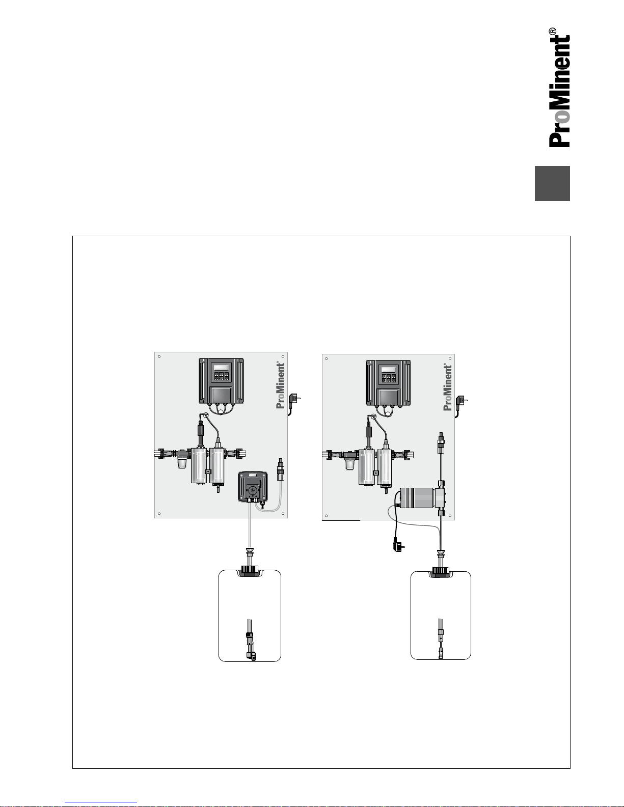
About this product
DULCODOS®
Pool metering systems are specifically designed for
the treatment of swimming pool water. Ready mounted, fully-wired
and ready for use, they provide disinfection using chlorine or bro‐
mine.
DULCODOS® Pool metering systems are equipped with all neces‐
sary components mounted on a plate.
n Sensors
n Controller
n Metering pumps
2.1
Overview of equipment
A1115
13.
12.
11.
10.
9.
8.
7.
6.
5.
4.
3.
2.
1.
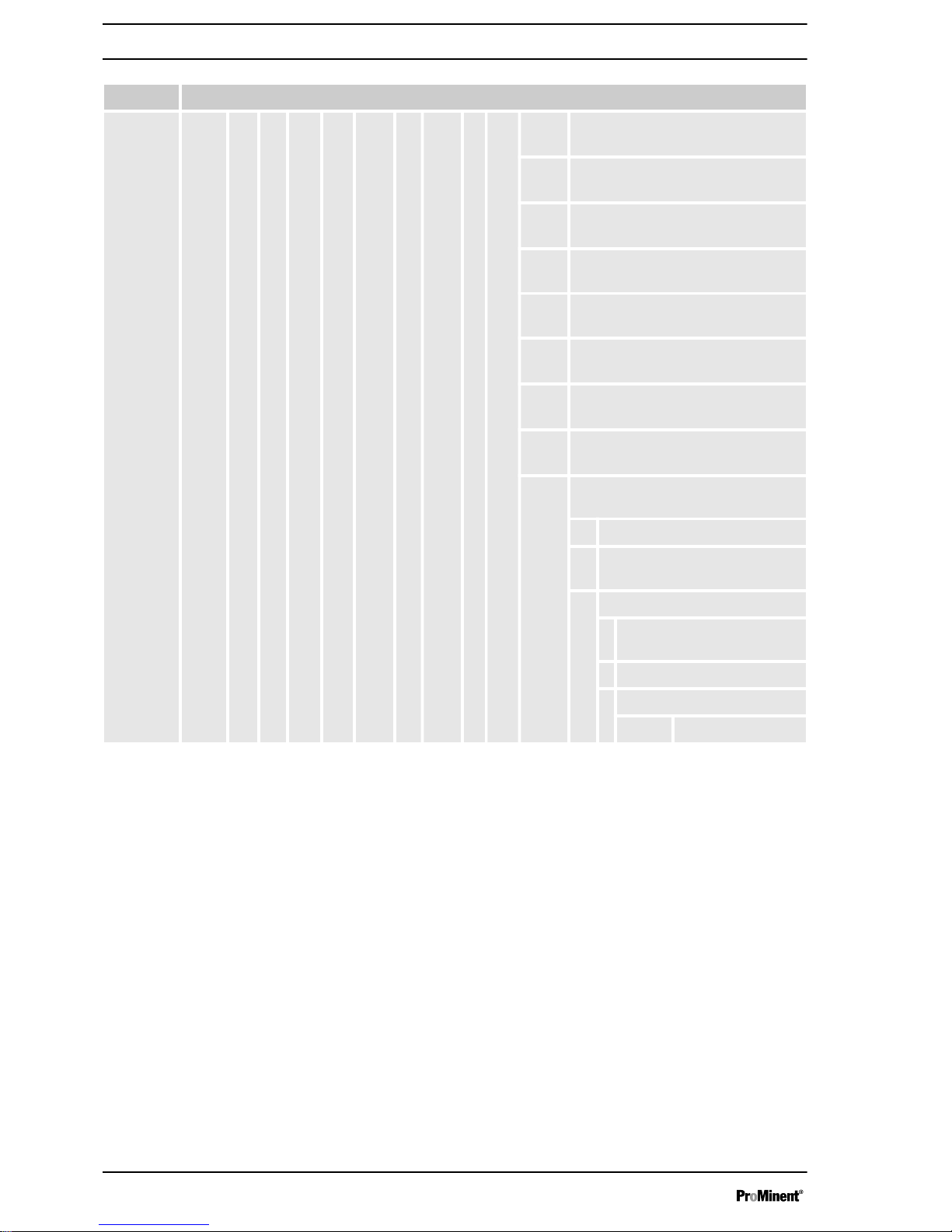
Fig. 1: Overview of equipment based on the example DULCODOS® Pool metering system R01 (with all
options and metering pump Beta® or DF2a)
1. Redox controller
2. Flow sensor
3. Redox sensor*
4. Flow module with flow sensor
5. Ball valve, inlet side
6. Disinfectant injection valve
7. Sampling tap
8.
Metering pump Beta® disinfectant
9 Cable disinfectant level switch (only
with metering pump )
10. Suction assembly disinfectant
11. Metering pump DF2a disinfectant
12. Dirt filter
13. Ball valve, outlet side
Not shown
in figure
Disinfectant multifunctional valve
* To be fitted by the customer. These
components are ready for subsequent
installation, but are supplied sepa‐
rately to avoid damage in transit.
Components P01
About this product
7
Page 8
2.
1.
4.
A1116
3.
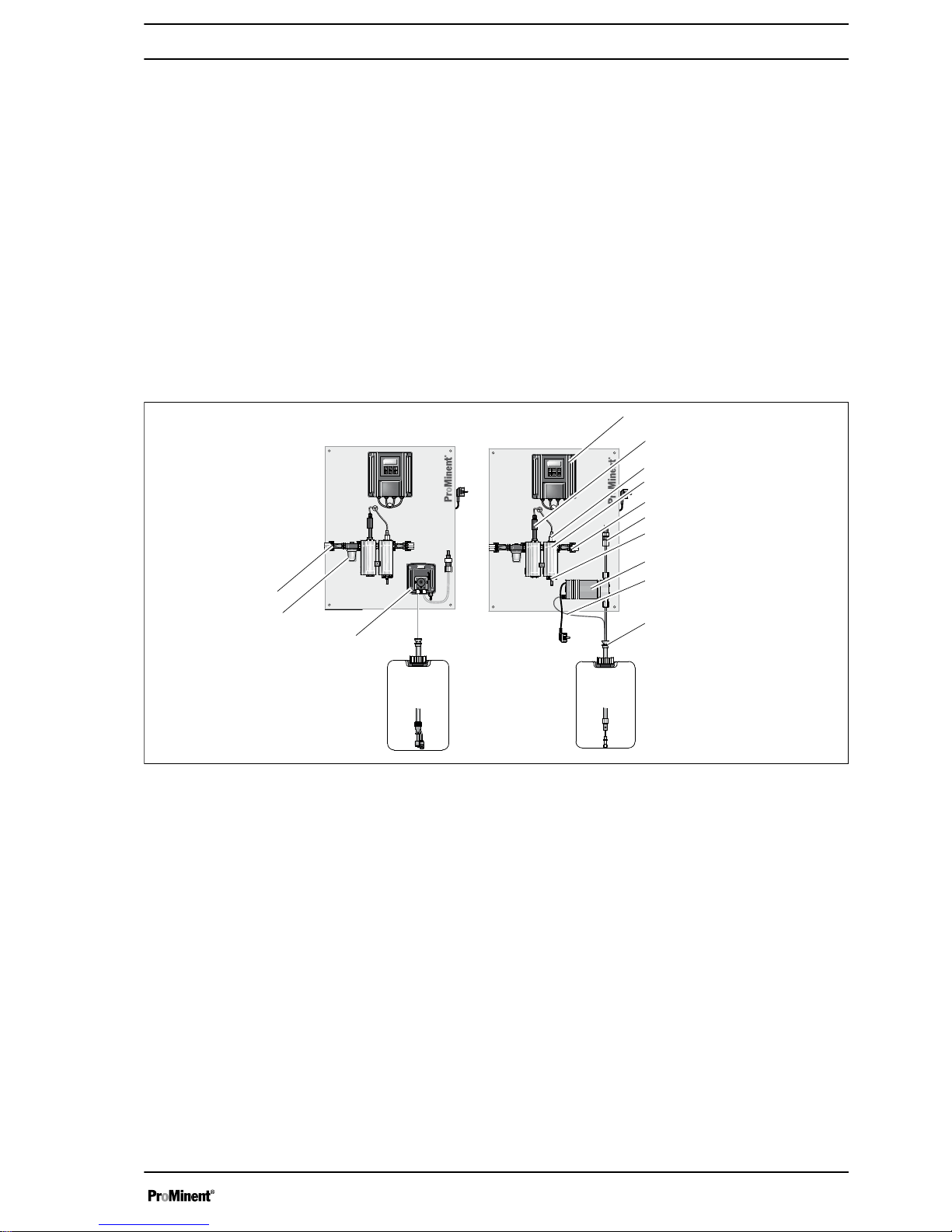
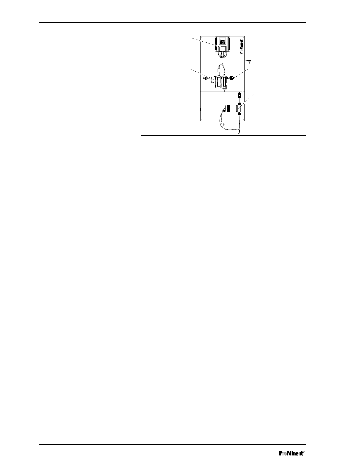
Fig. 2: Control elements for the example DULCODOS® Pool
metering system R01 (with all options and metering pumps Beta®)
The following are used as control elements:
1. Controller keys and display
2. Flow meter (by scale)
3 Stroke adjustment dial of the metering pump (con‐
cealed with the alpha pump)
4. Ball valve, in-line probe housing, inlet side
(Not shown in
figure)
Multifunctional valve
Control elements e.g. R01
About this product
8
Page 9

3
Safety and responsibility
3.1
Users' qualifications
WARNING!
Danger of injury with inadequately qualified personnel!
The operator of the plant / device is responsible for
ensuring that the qualifications are fulfilled.
If inadequately qualified personnel work on the unit or
loiter in the hazard zone of the unit, this could result in
dangers that could cause serious injuries and material
damage.
– All work on the unit should therefore only be con‐
ducted by qualified personnel.
–
Unqualified personnel should be kept away from
the hazard zone
Training Definition
Instructed personnel An instructed person is deemed to be a person who has been instructed and,
if required, trained in the tasks assigned to him/her and possible dangers that
could result from improper behaviour, as well as having been instructed in the
required protective equipment and protective measures.
Trained user A trained user is a person who fulfils the requirements made of an instructed
person and who has also received additional training specific to the system
from ProMinent or another authorised distribution partner.
Trained qualified per‐
sonnel
A qualified employee is deemed to be a person who is able to assess the
tasks assigned to him and recognize possible hazards based on his/her
training, knowledge and experience, as well as knowledge of pertinent regula‐
tions. The assessment of a person's technical training can also be based on
several years of work in the relevant field.
Electrician Electricians are deemed to be people, who are able to complete work on elec‐
trical systems and recognize and avoid possible hazards independently based
on his/her technical training and experience, as well as knowledge of pertinent
standards and regulations.
Electricians should be specifically trained for the working environment in
which the are employed and know the relevant standards and regulations.
Electricians must comply with the provisions of the applicable statutory direc‐
tives on accident prevention.
Customer Service depart‐
ment
Customer Service department refers to service technicians, who have
received proven training and have been authorised by ProMinent to work on
the system.
Note for the system operator
The pertinent accident prevention regulations, as well
as all other generally acknowledged safety regulations,
must be adhered to!
Safety and responsibility
9
Page 10
3.2
Explanation of the safety information
These operating instructions provide information on the technical
data and functions of the product. These operating instructions pro‐
vide detailed safety information and are provided as clear step-bystep instructions.
The safety information and notes are categorised according to the
following scheme. A number of different symbols are used to
denote different situations. The symbols shown here serve only as
examples.
DANGER!
Nature and source of the danger
Consequence: Fatal or very serious injuries.
Measure to be taken to avoid this danger
Danger!
–
Denotes an immediate threatening danger. If this is
disregarded, it will result in fatal or very serious
injuries.
WARNING!
Nature and source of the danger
Possible consequence: Fatal or very serious injuries.
Measure to be taken to avoid this danger
Warning!
–
Denotes a possibly hazardous situation. If this is
disregarded, it could result in fatal or very serious
injuries.
CAUTION!
Nature and source of the danger
Possible consequence: Slight or minor injuries, mate‐
rial damage.
Measure to be taken to avoid this danger
Caution!
–
Denotes a possibly hazardous situation. If this is
disregarded, it could result in slight or minor inju‐
ries. May also be used as a warning about material
damage.
NOTICE!
Nature and source of the danger
Damage to the product or its surroundings
Measure to be taken to avoid this danger
Note!
–
Denotes a possibly damaging situation. If this is
disregarded, the product or an object in its vicinity
could be damaged.
Introduction
Safety and responsibility
10
Page 11
Type of information
Hints on use and additional information
Source of the information, additional measures
Information!
–
Denotes hints on use and other useful information.
It does not indicate a hazardous or damaging sit‐
uation.
3.3
General Safety Information
WARNING!
Live parts!
Possible consequence: Fatal or very serious injuries
– Measure: Disconnect the mains power supply prior
to opening the housing
–
De-energise damaged, defective or manipulated
units by disconnecting the mains plug
WARNING!
Unauthorised access!
Possible consequence: Fatal or very serious injuries
– Measure: Ensure that there can be no unauthor‐
ised access to the unit
WARNING!
Operating errors!
Possible consequence: Fatal or very serious injuries
– The unit should only be operated by adequately
qualified and technically expert personnel
–
Please also observe the operating instructions for
controllers and fittings and any other component
groups, such as sensors, measuring water
pumps ...
– The operator is responsible for ensuring that per‐
sonnel are qualified
CAUTION!
Electronic malfunctions
Possible consequence: Material damage to destruction
of the unit
– The mains connection cable and data cable should
not be laid together with cables that are prone to
interference
–
Measure: Take appropriate interference suppres‐
sion measures
Safety and responsibility
11
Page 12

NOTICE!
Correct and proper use
Damage to the product or its surroundings
– The unit is not intended to measure or regulate
gaseous or solid media
–
The unit may only be used in accordance with the
technical details and specifications provided in
these operating instructions and in the operating
instructions for the individual components
NOTICE!
Correct sensor operation / Run-in time
Damage to the product or its surroundings
– Correct measuring and dosing is only possible if
the sensor is working perfectly
– It is imperative that the run-in times of the sensors
are adhered to
– The run-in times should be allowed for when plan‐
ning initial operation
– It may take a whole working day to run-in the
sensor
– Please read the operating instructions for the
sensor
NOTICE!
Correct sensor operation
Damage to the product or its surroundings
– Correct measuring and dosing is only possible if
the sensor is working perfectly
–
Check and calibrate the sensor regularly
NOTICE!
Compensation of control deviations
Damage to the product or its surroundings
– This controller cannot be used in control circuits
which require rapid compensation (< 30 s)
3.4
Correct and proper use
NOTICE!
Compensation for control deviations
Damage to the product or its surroundings
– The controller can be used in processes, which
require compensation of > 30 seconds
Safety and responsibility
12
Page 13

NOTICE!
Correct and proper use
The unit is intended to measure and regulate liquid
media. The marking of the measured variables is
located on the controller and is absolutely binding.
The unit may only be used in accordance with the
technical details and specifications provided in this
operating manual and in the operating manuals for the
individual components (such as, for example, sensors,
fittings, calibration devices, metering pumps etc.).
Any other uses or modifications are prohibited.
Safety and responsibility
13
Page 14

4
Storage and transport
CAUTION!
– Prior to storage or transport, the
DULCODOS® Pool metering systems
must be free
from feed chemicals and water
– Rinse out the media carrying parts, including the
tubes using clean, pure water
– Transport and store the DULCODOS® Pool
metering systems in their original packaging
– Also protect the packaged DULCODOS® Pool
metering systems against damp, exposure to
chemicals and mechanical effects
– Please also observe the operating instructions for
controllers and fittings and other units, such as
sensors, filters, metering pumps ...
Storage temperature: 0 ... 50 °C
Air humidity: < 95% relative air humidity, non-condensing
NOTICE!
If the DULCODOS® Pool metering systems are stored
as an assembly with the sensors, then the storage and
transport conditions must be appropriate for the com‐
ponent with the least resistance to external influences.
Ambient conditions for storage and
transport without sensors
Storage and transport
14
Page 15

5
Assembly
Cleaning the injection valve
Localised increases in pH can occur through the
metering of chlorine into the swimming pool water.
This can result in limescale forming in the injection
valve.
Regularly check, clean and descale the injection valve.
The frequency of this work depends on the usage and
ambient parameters of your system and must be deter‐
mined during operation.
To avoid bursting of the metering hose, with metering
pumps of type alpha and Beta®, a multifunctional
valve, identity code characteristic "Multifunctional valve
disinfection pump", must be fitted in the metering line.
5.1
Wall mounting
Secure the metering system perpendicular and upright
on a wall or a stable mounting system.
The metering system should be freely accessible.
Select the mounting height you require so that:
n The controller's display can be easily read
n the controller lid can still be parked in the
[Park position]
(150
mm)
n There is still space for maintenance work beneath the in-line
probe housing (100 mm)
n There is still room for the chemical storage tank (600 mm)
n The fluid level of the full chemical storage tanks is below the
metering pumps
n The maximum priming lift of the metering pumps is not
exceeded.
Assembly
15
Page 16

10 mm
A0924
1
2
3
4
Fig. 3: Hanger bolt
1 Rawlplug (type dependent on substrate and according to stipu‐
lations of the rawlplug manufacturer)
2 Hanger bolt
3 U-washer
4 Hexagon nut
5.2
Fit the antikink device for the bleed line
A0965
4.
3.
2.
1.
Fig. 4: Fit the antikink device for the bleed line (only SEK liquid
end)
1. Bleed valve for the return line in the storage tank, 6/4 mm
2. Red sleeve
3. Discharge valve for discharge line to injection point, 6/4 - 12/9
mm
4. Suction valve for suction line in storage tank, 6/4 - 12/9 mm
1. Fit the antikink device for the bleed line on the upper valve
(red sleeve)
2. route the bleed hose in the gutter of the antikink device
3. Pull the bleed hose downwards
ð
The bleed hose engages in the antikink device.
Only SEK liquid end (metering pump
Beta® for disinfection, right side):
Assembly
16
Page 17

5.3
Hydraulic installation
A1117
Fig. 5: Indoor swimming pool: hydraulic connection of the swimming pool metering system to the swimming
pool installation
Advantage: "Direct" measured values without depletion
Disadvantage: In-line probe housing can become dirty
Assembly
17
Page 18

A1118
Fig. 6: Outdoor swimming pool: hydraulic connection of the swimming pool metering system to the swimming
pool installation
Advantage: In-line probe housing cannot become dirty
Disadvantage: Measured values with depletion
5.3.1
Metering system
NOTICE!
Maximum permissible operating pressure of in-line
probe housing
Limit the pressure to a maximum of 2 bar (at 30 °C)
directly at the sample water extraction point using a
pressure reducer, otherwise the maximum permissible
operating pressure of the in-line probe housing will be
exceeded.
Do not allow a back pressure of more than 2 bar
(at 30 °C) to build up at the outlet, otherwise the max‐
imum permissible operating pressure of the in-line
probe housing will be exceeded.
1. With flow sensor: Push the flow sensor into the in-line probe
housing and tighten the reducing nipple and the mounting
clip
2. Route the sample water feed via a ball valve from the filter
circuit to the in-line probe housing, see figures above
3. Route the sample water feed via a ball valve from the filtra‐
tion circuit to the in-line probe housing, see figures above
4. Install a 1/2" straight union on the filtration circuit pipe for
each injection valve
Assembly
18
Page 19

5. Screw the injection valves into a straight union of the filtration
circuit pipe
1
2
3
4
5
6
A0929
Fig. 7: Connect the tube using the connector kit
1. Valve
2. O-ring
3. Nozzle
4. Clamp ring
5. Union nut
6. Hose
6. Connect the suction hose of the suction assembly to the con‐
nector kit on the liquid end
7. Connect the pressure hose to the pressure connector using
the connector kit
8. Connect the pressure hose to the injection valve using the
connector kit
To ensure reliable measuring and control, the sample
water must be free from air bubbles.
1. Set a flow of 20 ... 60 l/h using the stopcock (read-off at the
top edge of the float).
2. Check the hydraulic leak-tightness of the system (escaping
liquid, continuous air bubbles in the in-line probe housing, ...)
ð
Tighten the threaded connectors if necessary.
1.
Have a collecting vessel at the ready
Open the sampling tap
Testing the hydraulic installation of
the metering system:
Check the system for negative pres‐
sure
Assembly
19
Page 20

2. If water flows out of the sampling tap, the system is not under
negative pressure and is working correctly
If air is drawn in, this means that there is nega‐
tive pressure in the system. In this case, throttle
the valve at the point at which the sample water
pipe enters the filtration circuit - the pressure
should not exceed 2 bar.
3. Use the stopcock on the sample water drain to finely adjust
the system
5.3.2
Sensors
Observe the operating instructions for the sensors.
1. Close the shut-off valves upstream and downstream of the
in-line probe housing
2. Remove the transparent protective cap from the ball-shaped
end of the redox sensor
3. Manually screw the redox sensors into separate threaded
holes on the in-line probe housing. Then carefully tighten
using an SW 17 open-ended spanner until the threaded con‐
nector is tight
4. Testing the sensors' hydraulic installation: Adjust the flow
using the shut-off valve to 20... 60 l/h
ð
Check whether the threaded connectors on the in-line
probe housing are tight.
Redox sensor installation
Assembly
20
Page 21

If there is already sample water in the in-line probe
housing
Slowly lower the sensor into the in-line probe housing.
Otherwise the diaphragm of the sensor is over‐
stretched and the sensor delivers incorrect values.
1. Remove the securing bolt (1) using a 35 mm ring spanner
2. Fit the sensor with electrolyte as described in the sensor
operating instructions
3. Push the O-ring (4), then the assembly washer (5) onto the
sensor (3) from below
ð
The components must lie against the clamp disc (2)
4. Then push the securing bolt (1) from above onto the sensor
(3)
5. Carefully push the sensor (3) into the module (6) of the in-line
probe housing
6. Tighten the securing bolt (1) using a 35 mm ring spanner
7. Testing the sensors' hydraulic installation: Adjust the flow
using the shut-off valve to 20... 60 l/h
ð
Check whether the threaded connectors on the in-line
probe housing are tight.
5.4
Electrical installation
If power sockets are provided on the metering system,
then the socket on the side of the metering pump
should always be used. The power socket is controlled
so that it switches the pump which is installed on the
same side as it.
1. Screw the orange-coloured SN6 plugs onto the sensors
2. With level switch: Plug the plug of the level sensor cable into
the
[level]
socket of the metering pump
Installing a chlorine or bromine sen‐
sors
A0968
1.
2.
3.
4.
5.
6.
Fig. 8: Assembling the sensor
Assembly
21
Page 22

6
Start up
WARNING!
Danger from hazardous substances!
Possible consequence: Fatal or very serious injuries.
Please ensure when handling hazardous substances
that you have read the latest safety data sheets pro‐
vided by the manufacture of the hazardous substance.
The actions required are described in the safety data
sheet. Check the safety data sheet regularly and
replace, if necessary, as the hazard potential of a sub‐
stance can be re-evaluated at any time based on new
findings.
The system operator is responsible for ensuring that
these safety data sheets are available and that they
are kept up to date, as well as for producing an associ‐
ated hazard assessment for the workstations affected.
CAUTION!
Wear suitable protective equipment (gloves, protective
goggles,...) when commissioning.
Refer to the latest safety data sheets on the feed
chemicals.
NOTICE!
The sampling tap must be closed otherwise sample
water will escape.
The service technician is responsible for instructing the
operating and maintenance personnel during commis‐
sioning.
If power sockets are provided on the metering system,
then the socket on the side of the metering pump
should always be used. The power socket is controlled
so that it switches the pump which is installed on the
same side as it.
Maximum permissible operating pressure:
In the sample water line:
–
2 bar at 30 °C (sample water)
1. Tighten all threaded connectors prior to initial commissioning
2. Open the shut-off valves downstream of the metering pumps,
in the sample water line and also the shut-off valves in your
system
3. Insert the suction lances into the relevant chemical storage
tanks for disinfectant
Preparation:
Start up
22
Page 23

4. Plug the mains plug into the socket and switch on the mains
voltage
6.1
Priming and bleeding
Start the control process, if correctly installed, the lines bleed them‐
selves.
6.2
Adjust the flow sensor switching point
Sample water may escape.
1. Adjust the flow to 50 l/h using the ball valve
2. Hold the flow sensor in place and loosen the mounting clip a
little
3. Press the float to 40 l/h using the flow sensor
ð
The error message should disappear.
4. Hold the flow sensor in this position and tighten the mounting
clip
5. Then re-adjust the flow required using the ball valve
6. Acknowledge any error message that occurs
7. Reset any possible consequences of this in the overall instal‐
lation
8. Check the threaded connector for leak-tightness
6.3
Calibration
You have to regularly calibrate the sensor during ope‐
ration. That means: 24 hours after initial calibration
and then weekly thereafter.
Please take into account any differing national regula‐
tions.
The flow sensor should switch when
the flow falls (flow sensor is con‐
nected as an NC).
Start up
23
Page 24

WARNING!
Danger from hazardous substances!
Possible consequence: Fatal or very serious injuries.
Please ensure when handling hazardous substances
that you have read the latest safety data sheets pro‐
vided by the manufacture of the hazardous substance.
The actions required are described in the safety data
sheet. Check the safety data sheet regularly and
replace, if necessary, as the hazard potential of a sub‐
stance can be re-evaluated at any time based on new
findings.
The system operator is responsible for ensuring that
these safety data sheets are available and that they
are kept up to date, as well as for producing an associ‐
ated hazard assessment for the workstations affected.
There must be a chlorine or bromine concentration of approx.
0.5 ... 0.8 mg/l in the pool to be able to calibrate the sensors.
Example (without depletion losses): A swimming pool contains 60
m3, by way of example. To obtain a chlorine concentration of 0.5 ...
0.8 mg/l in this swimming pool, requires 0.20 ... 0.32 litres of 12 %
sodium-calcium hypochlorite (density (
ρ) 1.22 ± 0.02).
Meter in the required quantity of sodium-calcium hypochlorite
into the filtration circuit, either using the chlorine metering
pump or evenly distribute the quantity of sodium-calcium
hypochlorite needed into the swimming pool using a meas‐
uring cup.
ð
An even concentration can be expected once the reac‐
tion time has elapsed:
reaction time [h] = cup contents [m3] / circulation capacity
[m3/h]
Preparing the filtration circuit
Start up
24
Page 25

calibration
zero p.:
take over value?
4.00 mA
calibration
DPD-value
1.55 ppm
calibration
zero p.: 4.00 mA
slope
6.50 mA/ppm
calibration
zero p.: 4.00 mA
slope
6.50 mA/ppm
calibration
Zeropoint
4.00 mA
calibration
DPD-value
01.55 ppm
A0018_GB
14.00 mA
Fig. 9: Calibration of All Amperometric Measured Variables
Fault message Condition Remarks *
Calibration not possible!
Slope too low
Slope too low
(< 20 % of standard slope)
Repeat calibration
Calibration not possible!
Slope too high
Slope too high
(> 300 % of standard slope)
Repeat calibration
DPD value too low
DPD > x.xx ppm
DPD < 2 % of measuring range Repeat calibration after addition of
metering medium or fit sensor
suitable for the process
Calibration not possible!
Zero point low
< 3 mA
(only with 4 - 20 mA sensors)
Check sensor/cable
Repeat calibration in water without
metering medium
Calibration not possible!
Zero point high
> 5 mA
> 6 mA for 0.5 ppm chlorite
Check sensor/cable
Repeat calibration in water without
metering medium
* Please also note the operation manual for the respective sensor
Only the slope can be calibrated in the restricted operating menu of
the DULCOMETER®
D1Cb / D1Cc.
Both the zero point and the slope can be calibrated in the complete
operating menu of the DULCOMETER® D1Cb / D1Cc.
CAUTION!
Correct sensor operation / Run-in time
Damage to the product or its surroundings
– Correct measuring and dosing is only possible if
the sensor is working perfectly
–
Please read the operating manual for the sensor
– Please also read the operating manuals for the fit‐
tings and other components used
– It is imperative that the run in periods of the sen‐
sors are adhered to
– The run in periods should be allowed for when
planning commissioning
– It may take a whole working day to run-in the
sensor
Testing the sensor
Start up
25
Page 26

Necessity of calibrating the zero point
Calibration of the zero point is not generally necessary.
Calibration of the zero point is only necessary if the
sensor is operated at the lower limit of the measuring
range or if the 0.5 ppm sensor version is used.
During the calibration, the DULCOMETER® D1Cb / D1Cc sets the
control outputs to "0". Exception: a basic load or a manual control
value has been set, this remains active. The mA standard signal
outputs are frozen. The measured value frozen at the start of cali‐
bration is suggested as a DPD value. The DPD value can be set
using the arrow keys. Calibration is only possible if the DPD value
is ≥ 2 % of the measuring range of the sensor.
NOTICE!
Prerequisites for correct calibration of the sensor slope
– The DPD method required by the feed chemical
employed will be used
–
The run in period for the sensor has been adhered
to
– There is permitted and constant flow at the in-line
probe housing
– There is temperature equalisation between the
sensor and the sample water
– There is a constant pH value in the permitted
range
The sensor is fitted, flushed with sample water and connected
electrically to the DULCOMETER® D1Cb / D1Cc and run-in.
There has to be adequate feed chemical in the sample water for
calibration (> 2% of the measuring range of the sensor).
Remove sample water directly at the measuring point and deter‐
mine the content of metering medium in the sample water in "ppm"
using an appropriate reference method (e.g. DPD, titration etc.).
Enter this value as follows at the DULCOMETER® D1Cb / D1Cc:
1.
Select Calibration menu. Then press
ð
The current measured value will now be frozen.
2. Take a sample of water and perform a reference measure‐
ment within 15 minutes
3.
Select "DPD value" of unit to be calibrated using the key
4.
Continue with
5. If necessary, match the flashing ppm value to the value
determined with the measurement using the keys,
, and
ð
The mA value of the sensor shown in this display now
corresponds to the measured value in "ppm".
6.
Then press the following key twice
ð
The display now shows the value determined for the zero
point and slope. Refer to the Error Message table should
an error be displayed.
Calibration of amperometric sensors:
slope (in the reduced and complete
operating menu)
Start up
26
Page 27

Necessity of calibrating the zero point
Calibration of the zero point is not generally necessary.
Calibration of the zero point is only necessary if the
sensor is operated at the lower limit of the measuring
range or if the 0.5 ppm sensor version is used.
A container with water, which is free of additives that could falsify
the measured result, is needed for calibration. Immerse the dis‐
mounted, but still electrically connected to the
DULCOMETER® D1Cb / D1Cc, sensor in this water. Use the
sensor to stir the water for approx. 5 minutes until the measured
value displayed at the DULCOMETER® D1Cb / D1Cc is steady
and close to "0".
1.
Select Calibration menu. Then press
2.
Select "Zero point" of unit to be calibrated using the key
3.
Continue with
ð
A prompt is shown in the display
4.
Confirm prompt with the key
5.
Continue with
6. Apply the "zero point" displayed during calibration using the
key
7.
Then press
ð
Display shows the values determined.
8.
Then press
ð
Refer to the Error Message table should an error be dis‐
played.
NOTICE!
Then definitively calibrate the slope with a suitable ref‐
erence method (e.g. DPD. titration etc.).
Calibration of amperometric sensors:
Zero point (only in the complete oper‐
ating menu)
Start up
27
Page 28

NOTICE!
Testing the ORP Sensor
With ORP measured variables, the sensor is not cali‐
brated but tested according to its design
– Observe any notification of abnormal behaviour
when testing the ORP sensor
–
Should the test not be successful, replace the ORP
sensor
= automatic timing
check sensor
ORP
check sensor
ORP
sensor in buffer r
460 mV
check sensor
measuremactive
please wait!
check sensor
ORP
mea. val
buffer
460 mV
465 mV
permanent display 1
A0064_GB
460 m
V
Fig. 10: Testing ORP sensors
A container with a ORP buffer solution (e.g. 465 mV) is needed for
testing.
1.
Select the Test menu
2. Immerse ORP sensor in the ORP buffer solution containing
test container (e.g. 465 mV)
3.
Start test with
ð
Test is running.
A buffer value is suggested once the waiting time has
expired.
4.
Using keys , and adjust the displayed "buffer"
(flashing) value to the mV value of the ORP buffer solution in
the test container. Confirm the value with
.
ð
The D1Cb displays the status message of the ORP
sensor in plain text. If the ORP sensor is functioning cor‐
rectly, continuous display 1 will be displayed directly
5. If the ORP sensor is unclean or defective, the ORP sensor
should be cleaned, as described in the ORP sensor oper‐
ating instructions, or alternatively replaced
Should the result of the calibration lie outside of the specified error
limits, an error message will appear, see
Testing the ORP Sensor
Description of the Testing of ORP
Sensors
Start up
28
Page 29

7
Maintenance
WARNING!
Danger from hazardous substances!
Possible consequence: Fatal or very serious injuries.
Please ensure when handling hazardous substances
that you have read the latest safety data sheets pro‐
vided by the manufacture of the hazardous substance.
The actions required are described in the safety data
sheet. Check the safety data sheet regularly and
replace, if necessary, as the hazard potential of a sub‐
stance can be re-evaluated at any time based on new
findings.
The system operator is responsible for ensuring that
these safety data sheets are available and that they
are kept up to date, as well as for producing an associ‐
ated hazard assessment for the workstations affected.
Observe the operating instructions for the metering
pump (option), the in-line probe housing, the sensors,
dirt filter and multifunctional valve (optional).
Thoroughly flush the metering system with water
before carrying out maintenance.
You must now calibrate the sensors regularly. That
means: 24 hours after initial calibration and then
weekly thereafter. Take into account any differing
national regulations.
7.1
Maintenance work
An overview of maintenance work
Maintenance interval Maintenance task
daily Check swimming pool water values
weekly Visual inspection of metering system (flow meter)
Only with metering pump Beta®
Metering pump LEDs
Check storage tank liquid/powder levels
Check sensors
6 months Clean valves
Maintenance
29
Page 30

You must check the actual swimming pool water
values daily to guarantee the safe operation of your
swimming pool system.
1. Check the chlorine concentration using the DPD test (refer to
the operating instructions for the test kit)
2. Check the pH value using the phenol red test (refer to the
operating instructions for the test kit)
ð
If the swimming pool water values lie outside the toler‐
ance limits, then conduct additional tests, as described in
Ä ‘An overview of maintenance work’ Table on page 29
.
1. Regularly conduct a visual inspection of the metering system,
specifically the sensors and the flow meter with flow sensor
for:
n Air bubbles in the sample water
n The state of the sensors
n Leakages
n Correct flow values
n To ascertain whether the flow sensor is fastened correctly
onto the flow meter
n To ascertain whether the float is moving easily within the
flow meter: To do so, note down the flow value and then
change the flow value - the float should change position
ð
Call Customer service if one of these points is not cor‐
rect.
2.
Only with metering pump Beta®
Check the LEDs at the
metering pumps. Call service if:
n the red LED illuminates
n the yellow LED illuminates
n the green LED does not illuminate and the circulating
pump is running
3. Check the liquid/powder levels in the storage tanks
ð
Pour in feed chemical if the liquid/powder level has fallen
below 10 cm.
4. Check the sensors by calibrating them
1. Close the stopcocks upstream and downstream of the in-line
probe housing
2. Unscrew the filter bowl
3. Remove the filter insert and clean it without detergent
4. Insert the filter insert into the housing
5. Check the sealing ring and the sealing surfaces for cleanli‐
ness, and clean if necessary
6. Screw the filter bowl until tight
7. Open the stopcocks on the in-line probe housing
Maintenance interval:daily
Maintenance interval: weekly
Maintenance interval: 6 months
Clean dirt filter regularly:
Maintenance
30
Page 31

7.2
Troubleshooting
Use the operating instructions for controllers, sensors, in-line probe
housings, metering pumps and multifunctional valves (optional) to
eliminate functional faults or call Customer service.
7.3
Disposal of used parts
n Users' qualification: instructed persons, see
Ä Chapter 3.1
‘Users' qualifications’ on page 9
NOTICE!
Regulations governing disposal of used parts
– Note the current national regulations and legal
standards which apply in your country
ProMinent Dosiertechnik GmbH, Heidelberg will take back decon‐
taminated used devices providing that they are covered by ade‐
quate postage.
Maintenance
31
Page 32

8
Technical data
Refer to the product-specific operating instructions for
technical data on the controller, sensors, in-line probe
housing, metering pump and multifunctional valve.
Cleaning the injection valve
Localised increases in pH can occur through the
metering of chlorine into the swimming pool water.
This can result in limescale forming in the injection
valve.
Regularly check, clean and descale the injection valve.
The frequency of this work depends on the usage and
ambient parameters of your system and must be deter‐
mined during operation.
To avoid bursting of the metering hose, with metering
pumps of type alpha and Beta®, a multifunctional
valve, identity code characteristic "Multifunctional valve
disinfection pump", must be fitted in the metering line.
Maximum permissible operating pressure
n In the sample water line:
– without chlorine or bromine sensor: 2 bar at 30 °C (sample
water)
– with chlorine or bromine sensor: 1 bar at 30 °C (sample
water)
Sample water line connector
n 8x5 mm PE tube
Sample water filter element
n 300 µm
Weights
n with pumps: approx. 10 kg
n without pumps: approx. 5 kg
Materials
n Plate material: PP
n Materials, wetted: The wetted materials are resistant to the
media commonly used in swimming pools. Consult the oper‐
ating instructions for the individual components with other
media.
n Sample water filter: polypropylene, nylon, nitrile rubber, stain‐
less steel
Dimensions sheet
Technical data
32
Page 33

745
595
min. 150
min. 600
400
A1119
Fig. 11: Dimensions sheet. All dimensions in mm. Depth 150 mm
Technical data
33
Page 34

9
Systems
9.1
Spare parts and accessories
Spare parts
Spare parts Part no.
Chlorine sensor CLE 3-mA-2 ppm (for free chlorine) 792920
Spare diaphragm cap for CLE 3 815073
Electrolyte solution for chlorine sensor for CLE, 100ml506270
Chlorine sensor CLE 2-mA-2ppm (for organically
bound chlorine)
792843
Spare diaphragm cap for CGE 2 792862
Electrolyte solution for chlorine sensor for CGE, 50ml792892
Redox sensor RHES-Pt-SE 150703
Buffer solution 465 mV, 50 ml 506240
Chlorine metering pump spare parts kit (clear
acrylic):
BT4a 0401 NPB .... 1001666
BT4a 0402 NPB .... 1001667
BT4a 0404 NPB .... 1035334
Chlorine metering pump spare parts kit (clear
acrylic):
ALPc 1002 NPB ... 1001724
ALPc 1004 NPB ... 1001724
Spare tube, complete, PharMed® for DULCO® flex
1009480
Filter element 300 µm, stainless steel 1038867
Spare parts kits for metering pumps Beta® comprising:
n 1 x metering diaphragm
n 1 x suction valve, complete
n 1 x discharge valve, complete
n 2 x valve balls
n 1 x set of seals
n 1 x connector kit
Accessories
Accessories Part no.
Photometer: To detect chlorine and bromine 1039315
Systems
34
Page 35

9.2
EC Declaration of Conformity
We,
ProMinent Dosiertechnik GmbH
Im Schuhmachergewann 5 - 11
D - 69123 Heidelberg
hereby declare that the product identifiedbelowconformstothe basichealthand
safety
requirementsof the ECDirective,by virtue of its design and construction, and inthe configuration
placed on the market by us.
This declaration isno longer applicableifchangesare made tothe product without our authorisation.
Product description:
DULCODOS POOL swimming pool dosing system
Product type:
DSPa _ _ _ _ _ _ _ _ _ _ 0 _ 0 _ 1_
i.e. for installed systems without factory-fitted dosing pumps
Serialno.:
see type plate on the unit
Applicable
EC Low Voltage Directive (2006/95/EC)
EC Directives:
EC EMC Directive (2004/108/EC)
Applied harmonised standards,
EN 61010 - 1, EN 60335 -1,
especially:
EN 61000 -6 -1/2/3/4
Date/ Manufacturersignature:
09.03.2012
Name/ positionof the signatory:
Joachim Schall, Manager Innovation and Technology
EC Declaration of Conformity for Machinery
Fig. 12: EC Declaration of Conformity
Systems
35
Page 36

- Original -
We,
ProMinent Dosiertechnik GmbH
Im Schuhmachergewann 5 - 11
D - 69123 Heidelberg
hereby declare that the product identified below conforms to the basic health and safety
requirements of the EC Directive, by virtue of its design and construction,and in the configuration
placed on the market by us.
This declaration is no longer applicable if changes are made to the product without our authorisation.
Product description:
DULCODOS POOL swimming pool dosing system
Product type:
DSPa _ _ _ _ _ _ _ _ _ _ X _ X _ 1_
and X >
0
i.e. for installed systems with factory-fitted dosing pump
s
Serial no.:
see type plate on the unit
Applicable
EC Machinery Directive (2006/42/EC)
EC Directives:
EC EMC Directive (2004/108/EC)
The safety objectives of the Low Voltage Directive 2006/95/E
C
were complied with in accordance with Appendix 1, No. 1.5.
1
of the Machinery Directive 2006/42/E
C
Applied harmonised standards,
EN ISO 12100, EN 809
especially:
EN 61010 - 1, EN 60335 -1,
EN 61000 -6 -1/2/3/
4
Technical documentation was
Dr. Johannes Hartfiel
compiled by the authorised
Im Schuhmachergewann 5-11
representative for documentation:
D - 69123 Heidelberg
Date / Manufacturer signature:
09.03.2012
Name / position of the signatory:
Joachim Schall, Manager Innovation and Technology
EC Declaration of Conformity for Machinery
Fig. 13: EC Declaration of Conformity
Systems
36
Page 37

10
Index
A
Actuating outputs................................................. 26
Ambient conditions............................................... 14
C
Calibration............................................................ 25
Cleaning the injection valve................................. 32
D
Descaling the injection valve................................ 32
G
General non-discriminatory approach.................... 3
N
non-discriminatory approach.................................. 3
Q
Question: Can the injection valve become
blocked?............................................................... 32
Question: How and why must I calibrate the
product?............................................................... 23
Question: How can I store and transport the
product?............................................................... 14
Question: How do I calibrate the ORP sensor?... 28
Question: How do I calibrate the sensor?............ 25
Question: How do I eliminate functional faults?... 31
Question: How is the product hydraulically
connected and what connection versions are
available?............................................................. 17
Question: What ambient conditions need to
be taken into consideration?................................ 14
Question: What components does the product
include?.................................................................. 7
Question: What do I need to consider when
operating the product for the first time?............... 22
Question: What is the purpose of this product?..... 7
Question: What should I consider when
mounting the product on the wall?....................... 15
Question: What type of buffer solutions do I
need?................................................................... 28
R
Run-in times......................................................... 26
S
Safety information................................................ 10
Sensor function.................................................... 26
Standard signal outputs....................................... 26
Storage.................................................................
14
T
Transport.............................................................. 14
U
Users' qualifications............................................... 9
Z
Zero point calibration............................................ 26
Index
37
 Loading...