

Page 1

Supplementary instructions: PROFINET
A2666
®
DULCOMETER
®
Multi-parameter Controller diaLog DACb
EN
Please carefully read these operating instructions before use. · Do not discard.
The operator shall be liable for any damage caused by installation or operating errors.
The latest version of the operating instructions are available on our homepage.
Target group: trained electronics technicians982194 Version: BA DM 228 08/18 EN
Page 2

Supplemental directives
General non-discriminatory approach
Supplementary information
In order to make it easier to read, this document uses the male
form in grammatical structures but with an implied neutral sense. It
is aimed equally at both men and women. We kindly ask female
readers for their understanding in this simplification of the text.
Please read the supplementary information in its entirety.
Information
This provides important information relating to the
correct operation of the unit or is intended to make
your work easier.
Warning information
Warning information include detailed descriptions of the hazardous
situation.
The following symbols are used to highlight instructions, links, lists,
results and other elements in this document:
Tab. 1: More symbols
Symbol Description
Action, step by step.
⇨ Outcome of an action.
Links to elements or sections of these instructions or other applicable documents.
n
[Button]
List without set order.
Display element (e.g. indicators).
Operating element (e.g. button, switch).
‘Display /GUI’
CODE
Screen elements (e.g. buttons, assignment of function keys).
Presentation of software elements and/or texts.
2
Page 3

Table of contents
Table of contents
1
Supplementary Instructions for PROFINET®........................ 4
1.1 Prerequisites................................................................. 4
1.2 Terminal diagram for the DAC communication unit...... 4
1.3 Adjusting the Controller................................................ 4
1.3.1 General...................................................................... 4
1.3.2
1.4
1.4.1 General...................................................................... 6
1.4.2 Display....................................................................... 6
1.4.3
1.5 Installation..................................................................... 7
1.6 Operation...................................................................... 7
1.6.1 General...................................................................... 7
1.6.2 GSDML file................................................................ 7
1.6.3 Description of the DACa data objects........................ 8
1.7 Bit field definitions....................................................... 14
1.7.1 Status of the channel............................................... 14
1.7.2 Error of the channel................................................. 16
1.7.3 Warning of the channel............................................ 17
1.7.4 Potential-free relay................................................... 18
1.7.5 Settings of the channel configuration....................... 19
1.8 Diagnostic messages.................................................. 20
1.9 PLC Programmable Logic Controller error message
Configuring PROFINET®........................................... 4
Special Features in Active PROFINET® Mode............. 6
LEDs on the PROFINET® DP module....................... 6
and controller behaviour............................................. 20
3
Page 4
A1173
Communication
Communication
external connector
Socket M12x1 female
4-pin (D-coded)
green (A)
red (B)
green (A)
red (B)
external
communication
Plug M8x1
ext. connector
2x socket M12x1
Female 4-pin
(D-coded)
Switch
alternative
ext. WLAN router
e.g. TP link
TL-WR702N
Communication
2 x plugs
M8x1 (male)
Supplementary Instructions for PROFINET
1
Supplementary Instructions for PROFINET
1.1 Prerequisites
Personnel must be familiar with the contents of the "Assembly and
Operating Instructions for DULCOMETER® Multi-parameter Con‐
troller diaLog DACa".
The controller must have a PROFINET® module.
®
®
Validity of the supplementary instruc‐
tions
These supplementary instructions are only valid when used in con‐
junction with the operating instructions for the Multi-parameter
Controller diaLog DACb.
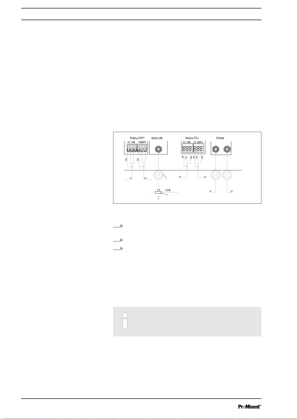
1.2 Terminal diagram for the DAC communication unit
Fig. 1: Terminal diagram for the DAC communication unit (module
B, optional)
1.
Connect the PROFINET® to the DAC communication unit,
Fig. 1.
2. Slot 1 is the left-hand
3. Slot 2 is the right-hand
[IN]
connector.
[OUT]
connector.
1.3 Adjusting the Controller
1.3.1 General
1.3.2
Configuring PROFINET
The controller with PROFINET® functionality is adjusted in the
same way as the standard controller, with the addition of the bus
functionality.
Adjustment process cancelled
The adjustment process is cancelled in the event
of a pause longer than 60 seconds.
®
Remote configuration needs to be enabled to be able to configure
and control the controller via the PROFINET®. The PROFINET® is
always enabled but it does not accept external commands if
remote configuration has not been enabled.
4
Page 5

Supplementary Instructions for PROFINET
All external inputs also work while the PROFINET® is enabled. The
external inputs lead to the expected reactions, as in the case of a
controller without PROFINET® functionality (see controller oper‐
ating instructions). The controller sends corresponding information
via the PROFINET® to the master (PLC Programmable Logic Con‐
troller, PC etc.).
Even if the remote configuration is set to inactive, the master is
able to read-access the controller data defined in the GSDML file.
If the remote configuration is inactive or switched to inactive, then
the settings for the operating mode selected prior to "inactive"
status are reloaded in the controller.
If the controller is switched to another operating mode, it stops and
can only be restarted using the
1. To access the
2. Use the arrow keys to select the menu item
firm with
The
ð
‘Menu’
[OK]
‘Device setup’
[Stop/Start]
: press the
menu appears.
[Menu]
key.
key
‘Setup’
and con‐
®
3. Use the arrow keys to select the menu item
configuration’
ð
In the
4.
n
n DHCP
n
n
n
n
n
The
‘Configuration’
‘Remote configuration’
– Switch remote configuration on or off.
– Switch DHCP on or off.
‘IP address’
– You can set the IP address here at which the con‐
‘Subnet’
– You can set the address of the subnet here.
‘Gateway’
– You can set the address of the gateway here.
‘DNS’
– You can set the address of the DNS here.
‘Station name’
– You can set the station name as an actual word e.g.
and confirm with
‘Configuration’
troller can be accessed.
"daca" or "daisy", using lower case letters only.
menu appears.
menu, you can:
[OK]
‘Bus
Origin of the designations
The different names and/or addresses represent
user-specific information and are the responsibility
of the system operator.
5
Page 6
Supplementary Instructions for PROFINET
1.4
Special Features in Active PROFINET® Mode
®
1.4.1 General
Setting or programming
In PROFINET® mode, the controller cannot be
manually set or programmed. Switch off remote
configuration to set or program the controller.
1.4.2 Display
1.4.3
LEDs on the PROFINET® DP module
n The settings from the last operating mode without PROFINET
are carried over when switching to PROFINET® mode. By con‐
trast, the settings made via the PROFINET® are not saved.
They only apply as long as the controller is linked to the PRO‐
FINET®.
n The controller stops if it is set to PROFINET® mode. The con‐
troller can be controlled again by pressing the
key. The start command is given via the PROFINET®.
When PROFINET® mode is running there are further identifiers in
the operating indicator.
[Stop/Start]
Common identifiers
The common identifiers are described in the con‐
troller operating instructions.
®
LED 1 (left) - module operating status
Signal Cause
Off The module has no supply voltage or connection.
Green The module and the master are exchanging information.
Green flashing The module has been initialised.
LED 2 (right) - module status
Signal Cause
Off The module has not been initialised.
Green The module has been initialised/normal mode
Green flashing, single flash The module has been initialised and there are diagnostic mes‐
sages.
Green flashing, 1 Hz DCP flash
Red Serious exception error
Red, single flash Configuration error
Red, double flash IP address error
6
Page 7
A1173
Communication
Communication
external connector
Socket M12x1 female
4-pin (D-coded)
green (A)
red (B)
green (A)
red (B)
external
communication
Plug M8x1
ext. connector
2x socket M12x1
Female 4-pin
(D-coded)
Switch
alternative
ext. WLAN router
e.g. TP link
TL-WR702N
Communication
2 x plugs
M8x1 (male)
Supplementary Instructions for PROFINET
Signal Cause
Red, triple flash Station name error
Red, quadruple flash Internal error
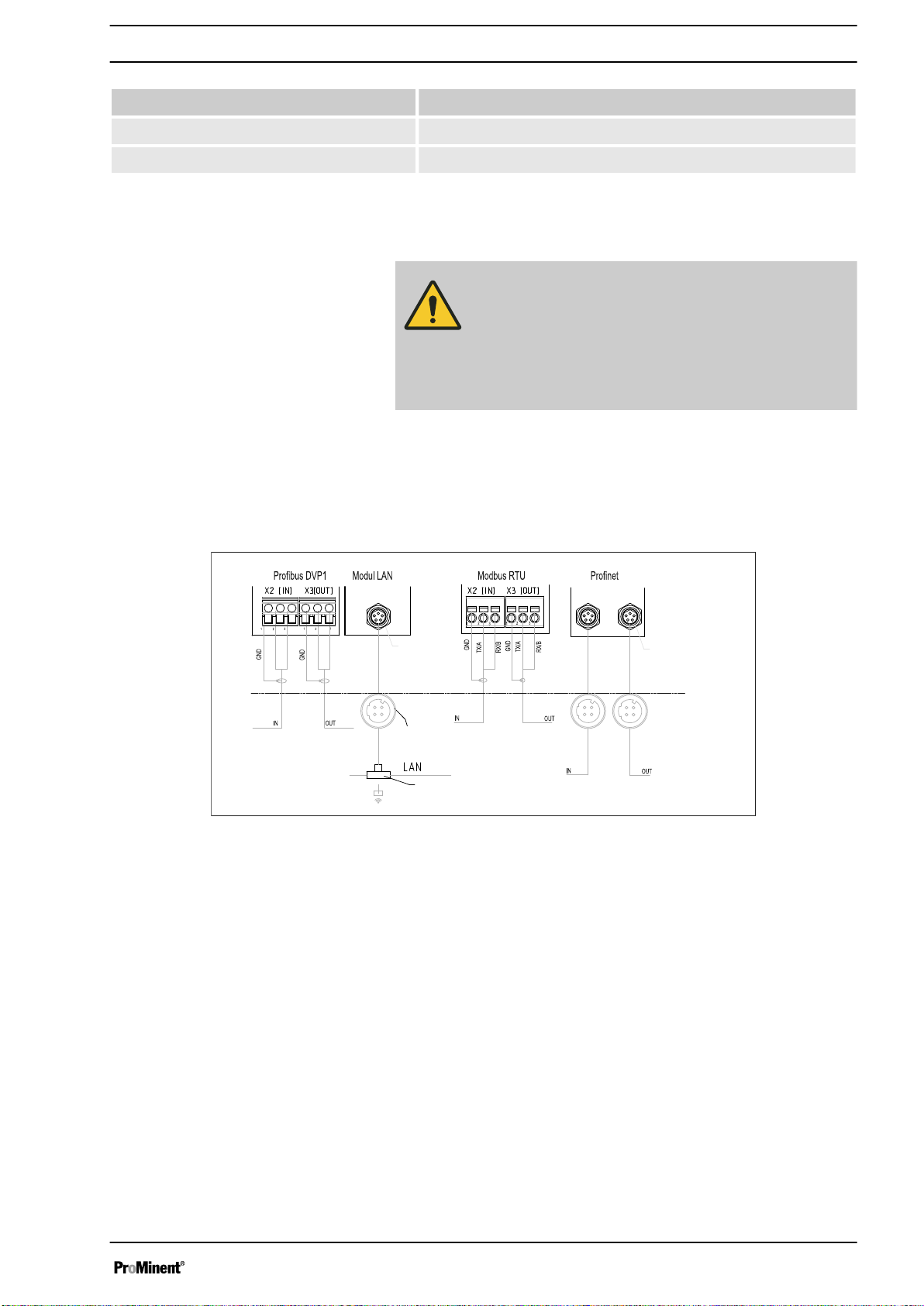
1.5 Installation
Bus installation
CAUTION!
Degree of protection IP 67
– IP 67 degree of protection only applies if the
appropriate assembly accessories (cable pas‐
sages etc.) have been correctly installed (see
controller assembly and operating instructions).
The connection to the existing LAN infrastructure is provided by a
suitable LAN cable, e.g. twisted pair cable (CAT5 or higher) to
comply with IP 67 with a screwed M12x1 plug, 4-pin, D-coded to
IEC 61076-2-101. Complies with IEEE 802.3.
Mains extension:
®
n Copper-based twisted pair cable (TP) maximum 100 metres.
Fig. 2: Terminal diagram of the communication modules
1.6 Operation
1.6.1 General
When the
PROFINET® represents a subscriber with slave functionality.
PROFINET®
module is connected, the controller in the
1.6.2 GSDML file
Use the GSDML file to configure the master. The GSDML file
describes all the features of the controller in PROFINET® mode
(keywords, diagnosis, modules, sub-modules). The GSDML file
can be downloaded from the PROFINET® website and from the
ProMinent website. The file name is clearly indicated: GSDMLV2.32-Prominent-DACa-PRT2P-20150721.xml .
7
Page 8

Supplementary Instructions for PROFINET
®
1.6.3 Description of the DACa data objects
Tab. 2: Output data
Slot Index Name Module name Data type Byte
count
Output data
Total:
Channel 1
1 2 Measured
1 3 Controller
1 4 Temperature INT16 2 0.1 °C
1 5 Setpoint FLOAT 4
1 6 Channel
‘Channel 1’
FLOAT 4
value
INT16 2
control vari‐
able
UINT16 2
status
Ä Chapter 1.7.1
‘Status of the
channel’
on page 14
1 7 Warnings UINT16 2
Ä Chapter 1.7.3
‘Warning of the
channel’
on page 17
Channel 2
2 2 Measured
‘Channel 2’
FLOAT 4
value
2 3 Controller
control vari‐
able
2 4 Temperature INT16 2 0.1 °C
2 5 Setpoint FLOAT 4
2 6 Channel
status
INT16 2
UINT16 2
Ä Chapter 1.7.1
‘Status of the
channel’
on page 14
2 7 Warnings UINT16 2
Ä Chapter 1.7.3
‘Warning of the
channel’
on page 17
Channel 3
3 2 Measured
3 3 Controller
‘Channel 3’
FLOAT 4
value
INT16 2
control vari‐
able
8
Page 9

Supplementary Instructions for PROFINET
®
Slot Index Name Module name Data type Byte
count
3 4 Temperature INT16 2 0.1 °C
3 5 Setpoint FLOAT 4
3 6 Channel
status
UINT16 2
Total:
Ä Chapter 1.7.1
‘Status of the
channel’
on page 14
3 7 Warnings UINT16 2
Ä Chapter 1.7.3
‘Warning of the
channel’
on page 17
Channel 4
(differential
channel)
4 1 Measured
4 2 Channel
‘Channel 4’
FLOAT 4
value
UINT16 2
status
Ä Chapter 1.7.1
‘Status of the
channel’
on page 14
4 3 Warnings UINT16 2
Ä Chapter 1.7.3
‘Warning of the
channel’
on page 17
Digital out‐
puts
5 1 Relay UINT16 2
‘digital output’
Ä Chapter 1.7.4
‘Potential-free
relay’
on page 18
5 2 MosFET 1 UINT16 2 Frequency
5 3 MosFET 2 UINT16 2 Frequency
5 4 MosFET 3 UINT16 2 Frequency
5 5 MosFET 4 UINT16 2 Frequency
Error
‘errors’
9
Page 10

Supplementary Instructions for PROFINET
®
Slot Index Name Module name Data type Byte
count
6 1 Error
channel 1
6 2 Error
channel 2
6 3 Error
channel 3
6 4 Error
channel 4
UINT32 4
UINT32 4
UINT32 4
UINT16 2
Total:
Ä Chapter 1.7.2
‘Error of the
channel’
on page 16
Ä Chapter 1.7.2
‘Error of the
channel’
on page 16
Ä Chapter 1.7.2
‘Error of the
channel’
on page 16
Ä Chapter 1.7.2
‘Error of the
channel’
on page 16
10
Page 11

Supplementary Instructions for PROFINET
Tab. 3: Input data
Slot Index Name Module name Data type Byte
count
Input data
®
Total:
Stop / Pause
(belongs to
the
‘Channel1/
Channel2’
module)
1 1
2 1
3 1
Controller
channel 1
‘Channel 1’
Stop / Pause
UINT8 1 Bit 7 = Stop
channel 1
‘Channel 2’
Stop / Pause
UINT8 1 Bit 7 = Stop
channel 2
‘Channel 3’
Stop / Pause
UINT8 1 Bit 7 = Stop
channel 3
‘controller
channel 1’
Bit 1 = Pause/
HOLD
Bit 0 = Pause
Bit 1 = Pause/
HOLD
Bit 0 = Pause
Bit 1 = Pause/
HOLD
Bit 0 = Pause
7 1 Configuration UINT16 2
7 2 Limit value 1
FLOAT 4
value
7 3 Limit value 2
FLOAT 4
value
7 4 Setpoint 1 FLOAT 4
7 5 Xp FLOAT 4
Controller
channel 2
‘controller
channel 2’
Ä Chapter
1.7.5 ‘Settings
of the channel
configuration’
on page 19
(Parameter
via bus,
mode, limit
value direc‐
tion, control
time)
11
Page 12

Supplementary Instructions for PROFINET
®
Slot Index Name Module name Data type Byte
count
8 1 Configuration UINT16 2
8 2 Limit value 1
value
8 3 Limit value 2
value
8 4 Setpoint 1 FLOAT 4
8 5 Xp FLOAT 4
Controller
channel 3
‘controller
channel 3’
FLOAT 4
FLOAT 4
Total:
Ä Chapter
1.7.5 ‘Settings
of the channel
configuration’
on page 19
(Parameter
via bus,
mode, limit
value direc‐
tion, control
time)
9 1 Configuration UINT16 2
9 2 Limit value 1
value
9 3 Limit value 2
value
9 4 Setpoint 1 FLOAT 4
9 5 Xp FLOAT 4
Error confir‐
mation
10 1 Error
‘error
confirmation’
channel 1
FLOAT 4
FLOAT 4
UINT32 4
Ä Chapter
1.7.5 ‘Settings
of the channel
configuration’
on page 19
(Parameter
via bus,
mode, limit
value direc‐
tion, control
time)
0xFFFFFFFF
*
=> all pending
errors have
been con‐
firmed
Ä Chapter
1.7.2 ‘Error of
the channel’
on page 16
12
Page 13

Supplementary Instructions for PROFINET
®
Slot Index Name Module name Data type Byte
count
10 2 Error
channel 2
10 3 Error
channel 3
10 4 Error
channel 4
UINT32 4
UINT32 4
UINT16 2
Total:
0xFFFFFFFF
*
=> all pending
errors have
been con‐
firmed
Ä Chapter
1.7.2 ‘Error of
the channel’
on page 16
0xFFFFFFFF
*
=> all pending
errors have
been con‐
firmed
Ä Chapter
1.7.2 ‘Error of
the channel’
on page 16
0xFFFF *
=> all pending
errors have
been con‐
firmed
Ä Chapter
1.7.2 ‘Error of
the channel’
on page 16
* These errors can also be deleted/acknowledged individually.
Controller
parameter
channel 1
11 1 Additive
11 2 Control vari‐
11 3 Delay after
11 4 Delay after
11 5 Setpoint 2 FLOAT 4 only with neu‐
‘controller
parameter ch1’
INT16 2
basic load
UINT16 2
able limit
UINT16 2
stop
UINT16 2
restart
tral zone con‐
trol
Controller
parameter
channel 2
‘controller
parameter ch2’
13
Page 14

Supplementary Instructions for PROFINET
®
Slot Index Name Module name Data type Byte
Total:
count
12 1 Additive
INT16 2
basic load
12 2 Control vari‐
UINT16 2
able limit
12 3 Delay after
UINT16 2
stop
12 4 Delay after
UINT16 2
restart
12 5 Setpoint 2 FLOAT 4 only with neu‐
tral zone con‐
trol
Controller
parameter
‘controller
parameter ch3’
channel 3
13 1 Additive
INT16 2
basic load
13 2 Control vari‐
UINT16 2
able limit
13 3 Delay after
UINT16 2
stop
13 4 Delay after
UINT16 2
restart
13 5 Setpoint 2 FLOAT 4 only with neu‐
tral zone con‐
trol
1.7 Bit field definitions
1.7.1 Status of the channel
Bit Description
15 1 = channel uses bus control parameters; 0 = channel uses internal parameters
14
13 1 = error exists; 0 = no error
12 1 = warning exists; 0 = no warning
11 1 = SD card full; 0 = SD card not full
10 1 = SD card free < 20%; 0 = SD card free ≧ 20%
9 1 = SD card exists; 0 = no SD card
8 1 = local control rate 2 active; 0 = local control rate 1 active
7
6
5
4
14
Page 15

Supplementary Instructions for PROFINET
Bit Description
3
2
1 1 = local stop active; 0 = no local stop active
0 1 = channel active; 0 = channel inactive (or cannot be connected)
®
15
Page 16

Supplementary Instructions for PROFINET
1.7.2 Error of the channel
Bit Description
®
31 Error 99: There is a system error;
30
29
28
27
26
25
24
23
22
21
20 Error 88: The connection to the extension module is faulty;
[A system error exists]
[The connection to the expansion module is faulty ]
19 Error 34: Incorrect correction variable;
18 Error 19: The liquid level in storage tank 3 is too low;
17 Error 18: The liquid level in storage tank 2 is too low;
[Incorrect correction variable ]
[The level in tank 3 is too low ]
[The level in tank 2 is too low ]
16 Error 17: The liquid level in storage tank 1 is too low;
15 Error 16: The mA input is overloaded;
14 Error 15: The mA input supply is overloaded;
13 Error 14: The status of the controller is pause / hold
[The mA input is overloaded]
[The mA input supply is overloaded]
[The level in tank 1 is too low ]
[PAUSE / HOLD]
;
[The controller is in the state PAUSE / HOLD]
12 Error 13: The status of the controller is pause
11 Error 12: There is a sample water fault e.g. no flow;
10 Error 11: After elapse of the delay period, a limit value error still exists;
[PAUSE]; [The controller is in the state PAUSE]
[Error sample water exists, e. g. no flow]
[After elapsing of the delay time a limit error still exists]
9 Error 10: The mA input current is less than 4 mA;
8 Error 9: The mA input current is greater than 20 mA;
[The mA input current is less than 4 mA ]
[The mA input current is greater than 20 mA ]
7 Error 8: The check time was infringed;
6 Error 7: Check the mechanical condition (glass breakage) of the sensor;
[The checkout time was infringed]
[Check the mechanical status of the sensor Glass break is possible]
5 Error 6: No sensor available;
4 Error 5: Calibration error exists;
3 Error 4: The temperature is too high;
[No sensor is available ]
[A calibration error exists]
[The temperature is too high]
2 Error 3: The temperature is too low;
1 Error 2: The mV input voltage is too high;
0 Error 1: The mV input voltage is too low;
[The temperature is too low ]
[The mV input voltage is too high ]
[The mV input voltage is too low ]
16
Page 17

1.7.3 Warning of the channel
Bit Description
15
14
13
12
11
10
9
8
7
Supplementary Instructions for PROFINET
®
6 Warning 73: The fan has a fault;
5 Warning 72 The time must be checked;
4 Warning 71 The battery needs to be replaced;
[The fan has an error]
[The time must be checked]
[The battery must be replace]
3 Warning 4 The measuring channel is not yet calibrated;
[The measuring channel is not yet calibrated]
2 Warning 3 The wash timer has timed out. Maintenance is required;
[The wash timer has timed out. Maintenance is necessary]
1 Warning 2 The limit value was exceeded;
0 Warning 1 The limit value was not reached;
[The limit was exceeded ]
[The limit was undershot]
17
Page 18

Supplementary Instructions for PROFINET
1.7.4 Potential-free relay
If relay output is active, then according bit is used.
Bit Description
15
14
13
12
11
10
9
8
7
6
®
5
4
3
2 Configuring alarm relay (XR3)
1 Relay 2 (XR2)
0 Relay 1 (XR1)
18
Page 19

Supplementary Instructions for PROFINET
1.7.5 Settings of the channel configuration
Bit Description
15 1 = Channel uses remote control parameters; 0 = Channel uses internal parameters;
[1 = Channel uses remote control parameters; 0 = Channel uses internal parameters]
14 1 = Channel uses internal set 2; 0 = Channel uses internal set 1;
[1 = Use internal parameter set 2; 0 = Use internal parameter set 1]
13
12
11
10
9
8 1 = Limit value 2 configuration on; 0 = limit value 2 configuration off
[1 = limit 2 configuration on; 0 = limit 2 configuration off]
7 1 = Limit value 1 configuration on; 0 = limit value 1 configuration off
[1 = limit 1 configuration on; 0 = limit1 configuration off]
®
6 0 = Control off;
[0 = Control off]
5
3 = P (1 way, decrease);
4
[3 = P (1 way, decrease)]
3
6 = PID (1 way, increase)
[6 = PID (1 way, increase) ]
9 = PID (2 way, dead zone)
1 = manual
[1 = manual]
4 = P (2 way, standard)
[ 4 = P (2 way, standard)]
7 = PID (1 way, decrease);
[7 = PID (1 way, decrease)]
[9 = PID (2 way, deadzone)]
2
1 1 = Limit value 2 configuration high; 0 = limit value 2 configuration low;
[1 = limit 2 configuration high; 0 = limit 2 configuration off]
0 1 = Limit value 1 configuration high; 0 = limit value 1 configuration low;
[1 = limit 1 configuration high; 0 = limit 1 configuration off ]
n Bit 14 is only valid if bit 15 = 0
n Bit 3, 4, 5, 6 are only valid if bit 15 = 1
n Bit 3, 4, 5, 6, 14, 15 only exists on channels 1 and 2
2 = P (1 way, increase)
[2 = P (1 way, increase)]
5 = P (2 way, dead zone)
[5 = P (2 way, deadzone)]
8 = PID (2 way, standard)
[ 8 = PID (2way, standard)]
19
Page 20

Supplementary Instructions for PROFINET
®
1.8 Diagnostic messages
The diagnostic messages are shown in plain text in the PLC Pro‐
grammable Logic Controller.
Error type Diagnostic messages
12755 Limit error when writing
12773 Limit error when reading
13011 Protected value
13029 Protected value
13267 Device not in remote mode
13285 Device not in remote mode
13523 Option not installed
13541 Option not installed
13779 Service not defined
13797 Service not defined
14035 Value cannot be changed
14053 Value cannot be changed
1.9 PLC Programmable Logic Controller error message and controller behaviour
PLC Programmable Logic Controller error message Controller behaviour
IOPS = bad stopped
Disconnected connection stopped
Mains power On stopped
20
Page 21

21
Page 22

22
Page 23

23
Page 24

ProMinent GmbH
Im Schuhmachergewann 5 - 11
69123 Heidelberg
Germany
Telephone: +49 6221 842-0
Fax: +49 6221 842-419
Email: info@prominent.com
Internet: www.prominent.com
982194, 1, en_GB
© 2018
 Loading...