

Page 1
Assembly and operating instructions
A2543
Universal relief valve
Universelles Überströmventil
DHV-UR
EN/DE
Please carefully read these operating instructions before use. · Do not discard.
The operator shall be liable for any damage caused by installation or operating errors.
The latest version of the operating instructions are available on our homepage.
Target group: trained users983439 Version: BA MOZ 042 03/18 DE
Page 2

Overall Table of Contents
Overall Table of Con‐
tents
EN Universal relief valve DHV-UR..... 4
1 About this product................... 9
1.1 Nameplate.......................... 10
1.2 Versions............................. 11
2 Safety chapter....................... 15
2.1 Labelling of Warning Infor‐
mation................................ 15
2.2 User qualification............... 17
2.3 General safety informa‐
tion..................................... 19
2.4 Intended use...................... 22
3 Storage and transport........... 23
3.1 Storage.............................. 23
3.2 Transport............................ 23
3.3 Packaging material............ 23
4 Assembly.............................. 24
4.1 Assembling the relief
valve................................... 24
4.2 Fitting a manometer
(optional)............................ 29
5 Commissioning..................... 30
5.1 Pressure/temperature dia‐
gram................................... 31
5.2 Initial commissioning.......... 32
5.3 Releasing pressure from
the relief valve.................... 33
5.4 Setting the relief valve........ 34
5.5 Setting the process pres‐
sure.................................... 36
6 Maintenance......................... 37
7 Repair................................... 38
7.1 Dismantling the relief
valve................................... 40
7.2 Inspecting and replacing
the parts............................. 45
7.3 Assembling the relief
valve................................... 47
8 Troubleshooting.................... 49
9 Use Parts Disposal/Declara‐
tion of Decontamination........ 51
10 Technical data..................... 52
10.1 Applied standards............ 59
11 DHV-UR spare parts........... 60
12 Exploded view drawing....... 62
12.1 Exploded view drawing of
DHV-UR PP_, PC_, PV_.. 62
12.2 Exploded view drawing of
DHV-UR SS..................... 63
12.3 Parts list........................... 64
13 Dimensional drawing........... 65
13.1 Dimensional drawing of
DHV-UR PVC, PP,
PVDF............................... 65
13.2 Dimensional drawing of
DHV-UR SS..................... 67
DE Universelles Überströmventil
DHV-UR..................................... 72
1 Über dieses Produkt............. 77
1.1 Typenschild........................ 78
1.2 Ausführungen..................... 79
2 Sicherheitskapitel.................. 83
2.1 Kennzeichnung der Warn‐
hinweise............................. 83
2.2 Benutzer-Qualifikation........ 85
2.3 Allgemeine Sicherheitshin‐
weise.................................. 87
2.4 Bestimmungsgemäße Ver‐
wendung............................ 90
3 Lagern und transportieren .... 91
3.1 Lagern................................ 91
3.2 Transport............................ 91
3.3 Verpackungsmaterial......... 91
4 Montieren.............................. 92
2
Page 3

4.1 Das Überströmventil mon‐
tieren.................................. 92
4.2 Ein Manometer montieren
(Option).............................. 97
5 Inbetriebnahme..................... 98
5.1 Druck-Temperatur-Dia‐
gramm................................ 99
5.2 Erstinbetriebnahme.......... 100
5.3 Druckentlasten des Über‐
strömventils...................... 101
5.4 Überströmventil einstellen 102
5.5 Prozessdruck einstellen... 104
6 Wartung.............................. 105
7 Reparieren.......................... 106
7.1 Überströmventil zerlegen 108
7.2 Teile untersuchen und aus‐
tauschen.......................... 113
7.3 Überströmventil zusam‐
mensetzen....................... 115
8 Funktionsstörungen
beheben.............................. 117
9 Altteileentsorgung/Dekonta‐
minationserklärung.............. 119
10 Technische Daten............. 120
10.1 Angewandte Normen..... 127
11 Ersatzteile DHV-UR.......... 128
12 Explosionszeichnung........ 130
12.1 Explosionszeichnung
DHV-UR PP_, PC_ und
PV_ ............................... 130
12.2 Explosionszeichnung
DHV-UR SS................... 131
12.3 Stückliste........................ 132
13 Maßblatt............................ 133
13.1 Maßblatt DHV-UR PVC-
U, PP, PVDF ................. 133
13.2 Maßblatt DHV-UR SS.... 135
Overall Table of Contents
3
Page 4
Assembly and operating instructions
A2543
Universal relief valve
DHV-UR
EN
Please carefully read these operating instructions before use. · Do not discard.
The operator shall be liable for any damage caused by installation or operating errors.
The latest version of the operating instructions are available on our homepage.
Target group: trained usersPart number 983439 Version: BA MOZ 042 03/18 EN
Page 5
Supplemental directives
General non-discriminatory approach In order to make it easier to read, this
document uses the male form in grammat‐
ical structures but with an implied neutral
sense. It is aimed equally at both men and
women. We kindly ask female readers for
their understanding in this simplification of
the text.
Supplementary information
Please read the supplementary information in its entirety.
Information
This provides important information relating to the correct operation of the unit or
is intended to make your work easier.
Warning information
Warning information includes detailed descriptions of the hazardous situation, see
Ä Chapter 2.1 ‘Labelling of Warning Information’ on page 15
.
The following symbols are used to highlight instructions, links, lists, results and other ele‐
ments in this document:
Tab. 1: More symbols
Symbol Description
Action, step by step.
⇨ Outcome of an action.
Links to elements or sections of these instructions or other applicable
documents.
n
[Button]
List without set order.
Display element (e.g. indicators).
Operating element (e.g. button, switch).
5
Page 6

Supplemental directives
Symbol Description
‘Display /GUI’
CODE
Screen elements (e.g. buttons, assignment of function keys).
Presentation of software elements and/or texts.
6
Page 7

Table of contents
Table of contents
1 About this product................................................................................................... 9
1.1 Nameplate.................................................................................................... 10
1.2 Versions....................................................................................................... 11
1.2.1 Design of the standard version.................................................................. 11
1.2.2 Design with FDA approval......................................................................... 12
1.2.3 Version configured for manometer............................................................ 13
2 Safety chapter....................................................................................................... 15
2.1 Labelling of Warning Information.................................................................. 15
2.2 User qualification.......................................................................................... 17
2.3 General safety information........................................................................... 19
2.3.1 Information in the event of an emergency................................................. 21
2.4 Intended use................................................................................................. 22
3 Storage and transport........................................................................................... 23
3.1 Storage......................................................................................................... 23
3.2 Transport...................................................................................................... 23
3.3 Packaging material....................................................................................... 23
4 Assembly.............................................................................................................. 24
4.1 Assembling the relief valve........................................................................... 24
4.1.1 Installation examples................................................................................. 28
4.2 Fitting a manometer (optional)..................................................................... 29
5 Commissioning..................................................................................................... 30
Pressure/temperature diagram..................................................................... 31
5.1
5.2 Initial commissioning.................................................................................... 32
5.3 Releasing pressure from the relief valve...................................................... 33
5.4 Setting the relief valve.................................................................................. 34
5.5 Setting the process pressure........................................................................ 36
6 Maintenance......................................................................................................... 37
7 Repair................................................................................................................... 38
Dismantling the relief valve.......................................................................... 40
7.1
7.2 Inspecting and replacing the parts............................................................... 45
7.3 Assembling the relief valve........................................................................... 47
8 Troubleshooting.................................................................................................... 49
7
Page 8

Table of contents
9 Use Parts Disposal/Declaration of Decontamination............................................ 51
10 Technical data...................................................................................................... 52
10.1 Applied standards....................................................................................... 59
11 DHV-UR spare parts............................................................................................. 60
12 Exploded view drawing......................................................................................... 62
12.1 Exploded view drawing of DHV-UR PP_, PC_, PV_................................... 62
12.2 Exploded view drawing of DHV-UR SS...................................................... 63
12.3 Parts list...................................................................................................... 64
13 Dimensional drawing............................................................................................ 65
13.1 Dimensional drawing of DHV-UR PVC, PP, PVDF.................................... 65
13.2 Dimensional drawing of DHV-UR SS......................................................... 67
14 Index..................................................................................................................... 69
8
Page 9
A2538
About this product
1 About this product
The relief valve protects pumps from impermissible overpressure caused by operational
faults or blockages.
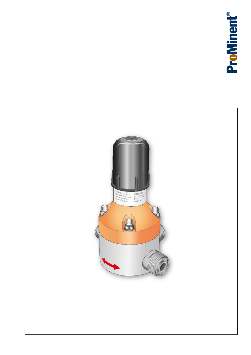
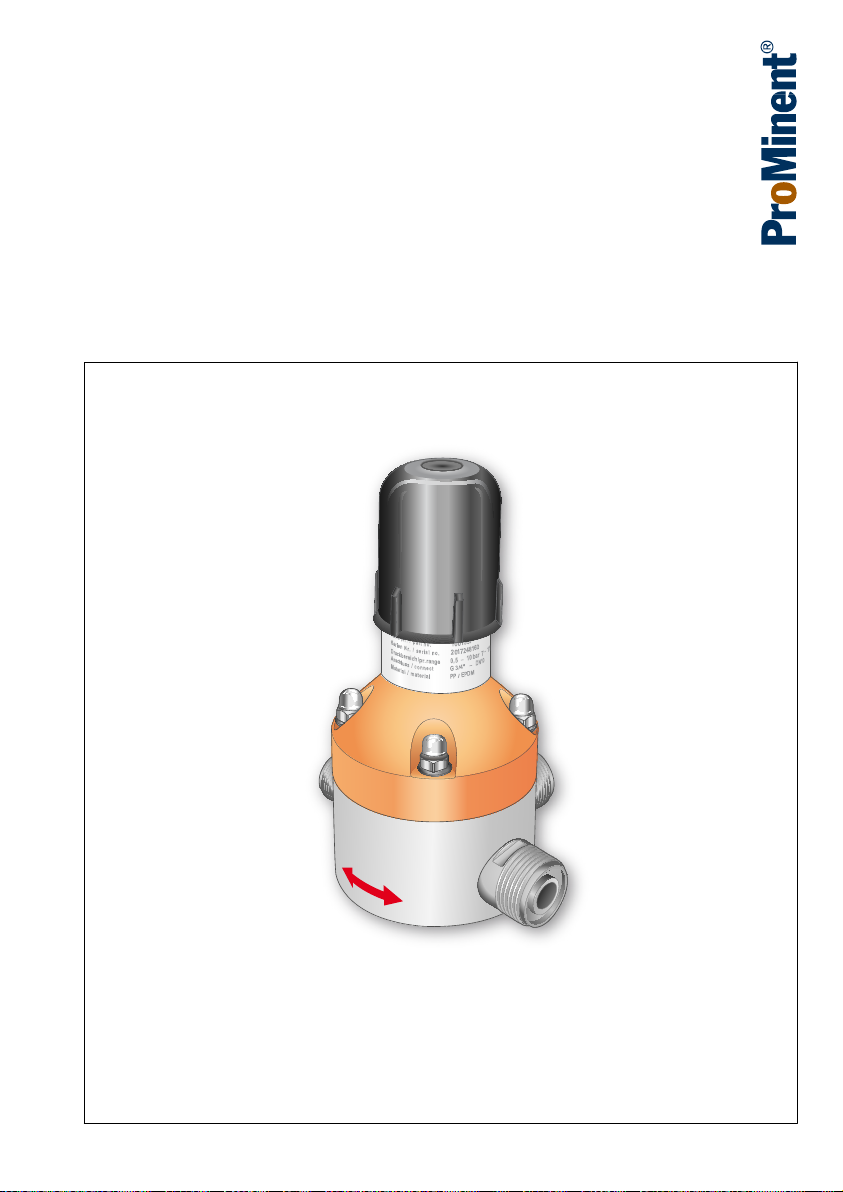
The universal relief valve type DHV-UR is a continuously adjustable plunger diaphragm
valve with an internal flow. In the event of impermissible overpressure, the internal
plunger diaphragm opens the second outlet line, the relief outlet. The relief valve can be
installed at any location in the pipework system. There are only very low pressure losses
due to the virtually free pipe cross-section.
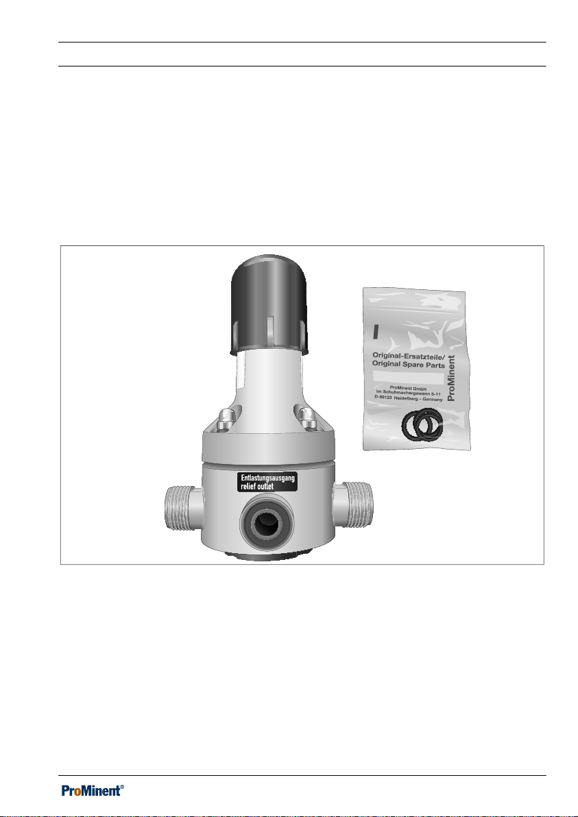
Fig. 1: Scope of delivery: relief valve with seals for the connector.
A manometer can also be installed on the “M” version of the relief valve DHV-UR.
The relief valve is also available as an FDA-approved version.
9
Page 10
A2539
About this product
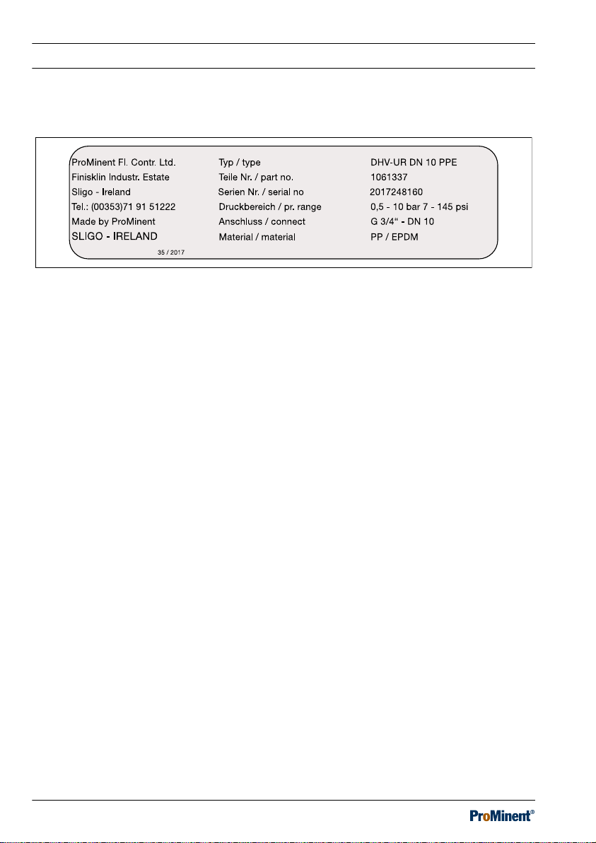
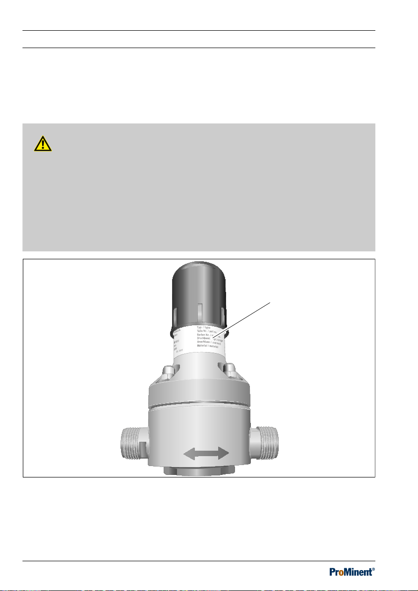
1.1 Nameplate
Fig. 2: Nameplate
The nameplate provides information on:
n Manufacturer with address and phone number
n Place and country of origin,
n Manufacturing data –– week / year
n Type of device with diameter and material version
n Part number
n Serial number
n Pressure range in bar und psi
n Connector size in inches and millimetres
n Material version
[Teile Nr. / part no.]
[Serien Nr. / serial no.]
[Druckbereich / pr. range]
[Material / material]
,
[Anschluss / connect]
.
[Typ / type]
,
,
10
Page 11
About this product
1.2 Versions
1.2.1 Design of the standard version
Tab. 2: Design: standard
Design Nominal width Thread in inches Order number
PPE DN 10 3/4 1061337
PPB DN 10 3/4 1061341
PCE DN 10 3/4 1061339
PCB DN 10 3/4 1061343
PVT DN 10 3/4 1061365
SST DN 10 3/4 1061550
PPE DN 15 1 1061336
PPB DN 15 1 1061340
PCE DN 15 1 1061338
PCB DN 15 1 1061342
PVT DN 15 1 1061364
SST DN 15 1 1061551
PPE DN 20 1 1/4 1061367
PPB DN 20 1 1/4 1061371
PCE DN 20 1 1/4 1061369
PCB DN 20 1 1/4 1061373
PVT DN 20 1 1/4 1061375
SST DN 20 1 1/4 1061569
PPE DN 25 1 1/2 1061366
PPB DN 25 1 1/2 1061370
PCE DN 25 1 1/2 1061368
PCB DN 25 1 1/2 1061372
11
Page 12
About this product
Design Nominal width Thread in inches Order number
PVT DN 25 1 1/2 1061374
SST DN 25 1 1/2 1061570
1.2.2 Design with FDA approval
Tab. 3: Design: FDA
Design Nominal width Thread in inches Order number
PPE DN 10 3/4 1075828
PVT DN 10 3/4 1075830
SST DN 10 3/4 1075847
PPE DN 15 1 1075827
PVT DN 15 1 1075829
SST DN 15 1 1075846
PPE DN 20 1 1/4 1075833
PVT DN 20 1 1/4 1075845
SST DN 20 1 1/4 1075849
PPE DN 25 1 1/2 1075832
PVT DN 25 1 1/2 1075844
SST DN 25 1 1/2 1075848
All wetted materials in the "Physiologically safe (FDA) in respect of wetted materials"
design comply with the following FDA guidelines:
FDA guidelines for the materials:
n PTFE: 21CFR177.1510,
n PVDF: 21CFR177.2510,
n PP: 21CFR177.1520,
n EPDM/FKM: 21CFR177.2600.
12
Page 13
About this product
1.2.3 Version configured for manometer
The “M” version of relief valve DHV-UR is configured with an opening in the housing for
installation of a manometer. Manometers with a G 1/4“ (ISO 228) threaded socket can be
fitted directly by the customer.
Tab. 4: Design: relief valve type DHV-UR M configured for manometer
Design Nominal width Thread in inches Order number
PPE DN 10 3/4 1077221
PPB DN 10 3/4 1077259
PCE DN 10 3/4 1077255
PCB DN 10 3/4 1077263
PVT DN 10 3/4 1077267
PPE DN 15 1 1077220
PPB DN 15 1 1077258
PCE DN 15 1 1077254
PCB DN 15 1 1077262
PVT DN 15 1 1077266
PPE DN 20 1 1/4 1077219
PPB DN 20 1 1/4 1077257
PCE DN 20 1 1/4 1077223
PCB DN 20 1 1/4 1077261
PVT DN 20 1 1/4 1077265
PPE DN 25 1 1/2 1077218
PPB DN 25 1 1/2 1077256
PCE DN 25 1 1/2 1077222
PCB DN 25 1 1/2 1077260
PVT DN 25 1 1/2 1077264
13
Page 14

About this product
14
Page 15
2 Safety chapter
A2540
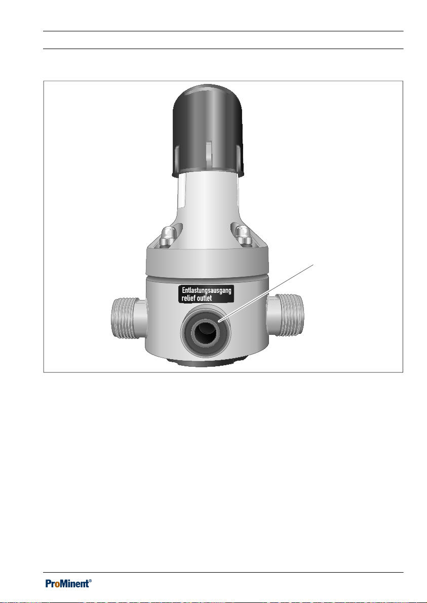
The adhesive labels and signs on the device e.g.:
Fig. 3: Relief outlet [Entlastungsausgang/relief outlet] / Flow direction
n Labels for fluid connectors,
n Direction of flow arrow,
n Nameplate,
must be observed and maintained in a fully legible condition.
2.1 Labelling of Warning Infor‐
mation
Introduction
These operating instructions provide infor‐
mation on the technical data and functions
of the product. These operating instruc‐
tions provide detailed warning information
and are provided as clear step-by-step
instructions.
The warning information and notes are
categorised according to the following
scheme. A number of different symbols
are used to denote different situations.
The symbols shown here serve only as
examples.
DANGER!
Nature and source of the danger
Consequence: Fatal or very
serious injuries.
Measure to be taken to avoid this
danger.
Description of hazard
– Denotes an immediate threat‐
ening danger. If the situation is
disregarded, it will result in
fatal or very serious injuries.
Safety chapter
15
Page 16

Safety chapter
WARNING!
Nature and source of the danger
Possible consequence: Fatal or
very serious injuries.
Measure to be taken to avoid this
danger.
– Denotes a possibly hazardous
situation. If the situation is dis‐
regarded, it could result in fatal
or very serious injuries.
CAUTION!
Nature and source of the danger
Possible consequence: Slight or
minor injuries. Material damage.
Measure to be taken to avoid this
danger.
– Denotes a possibly hazardous
situation. If the situation is dis‐
regarded, it could result in
slight or minor injuries. May
also be used as a warning
about material damage.
NOTICE!
Nature and source of the danger
Damage to the product or its sur‐
roundings.
Measure to be taken to avoid this
danger.
– Denotes a possibly damaging
situation. If the situation is dis‐
regarded, the product or an
object in its vicinity could be
damaged.
Type of information
Hints on use and additional infor‐
mation.
Source of the information. Addi‐
tional measures.
–
Denotes hints on use and
other useful information. It
does not indicate a hazardous
or damaging situation.
16
Page 17
Safety chapter
2.2 User qualification
WARNING!
Danger of injury with inadequately qualified personnel
The operator of the system / equipment is responsible for ensuring that the qualifi‐
cations are fulfilled.
If inadequately qualified personnel work on the unit or loiter in the hazard zone of
the unit, this could result in dangers that could cause serious injuries and material
damage.
– All work on the unit should therefore only be conducted by qualified per‐
sonnel.
– Unqualified personnel should be kept away from the hazard zone.
The pertinent accident prevention regulations, as well as all other generally
acknowledged safety regulations, must be adhered to.
Training Definition
Instructed personnel An instructed person is deemed to be a person who has been
instructed and, if required, trained in the tasks assigned to him
and possible dangers that could result from improper behav‐
iour, as well as having been instructed in the required protective
equipment and protective measures.
Trained user A trained user is a person who fulfils the requirements made of
an instructed person and who has also received additional
training specific to the system from the manufacturer or another
authorised distribution partner.
Trained, qualified
personnel
A trained, qualified employee is deemed to be a person who is
able to assess the tasks assigned to him and recognize pos‐
sible hazards based on his training, knowledge and experience,
as well as knowledge of pertinent regulations. A trained, quali‐
fied employee must be able to perform the tasks assigned to
him independently with the assistance of drawing documenta‐
tion and parts lists. The assessment of a person's technical
training can also be based on several years of work in the rele‐
vant field.
17
Page 18

Safety chapter
Training Definition
Electrical technician An electrical technician is able to complete work on electrical
systems and recognise and avoid possible dangers independ‐
ently based on his technical training and experience as well as
knowledge of pertinent standards and regulations. An electrical
technician must be able to perform the tasks assigned to him
independently with the assistance of drawing documentation,
parts lists, terminal and circuit diagrams. The electrical techni‐
cian must be specifically trained for the working environment in
which the electrical technician is employed and be conversant
with the relevant standards and regulations.
Service The Service department refers to service technicians, who have
received proven training and have been authorised by the man‐
ufacturer to work on the system.
18
Page 19
2.3 General safety information
WARNING!
Danger from hazardous sub‐
stances!
Possible consequence: Fatal or
very serious injuries.
Please ensure when handling haz‐
ardous substances that you have
read the latest safety data sheets
provided by the manufacture of the
hazardous substance. The actions
required are described in the
safety data sheet. Check the safety
data sheet regularly and replace, if
necessary, as the hazard potential
of a substance can be re-evaluated
at any time based on new findings.
The system operator is responsible
for ensuring that these safety data
sheets are available and that they
are kept up to date, as well as for
producing an associated hazard
assessment for the workstations
affected.
Safety chapter
WARNING!
Feed chemical can escape from
the DHV.
In the event of a diaphragm rupture
or insufficiently tightened housing
screws, feed chemical can escape
from between the housing parts or
through the adjusting screw.
Feed chemical can leak out from
insufficiently tightened sealing
stoppers or manometers.
– Produce an appropriate action
plan, based on these operating
instructions and the material
safety data sheet for your feed
chemical, to be used in the
event of uncontrolled leakage
of feed chemical.
CAUTION!
FDA valves only: problems with
hygiene are possible
The valves and the seals supplied
can become dirty from the pack‐
aging and shipment.
– Thoroughly clean the seals
supplied before use and flush
through the relief valve.
19
Page 20

Safety chapter
n Only the flow volume of the con‐
nected pump can be re-directed with
the DHV-UR.
n Take appropriate precautions on the
system when using as a relief valve
with sticky media, for example with
styrene: rinse the relief valve if it has
possibly reacted.
n Prior to installation, remove water
from the relief valve if it is to be used
together with media that may not
come into contact with water.
n The DHV-UR relief valve is not a
safety valve according to DIN EN ISO
4126-1.
n The DHV-UR relief valve is not
intended for use as a completely leaktight shut-off device.
n The DHV-UR relief valve is not
intended for use with gaseous media
or solids.
n Do not use the DHV-UR relief valve
with abrasive or crystallising media.
n Do not allow the DHV-UR relief valve
to come into contact with liquids,
which corrode the material of the
relief valve. This also applies to
cleaning agents and fats. Refer to the
ProMinent Resistance List in the
product catalogue or at www.promi‐
nent.com in this respect.
n Do not operate the relief valve outside
the ambient and operating conditions
specified in these operating instruc‐
tions.
n Only allow trained and authorised per‐
sonnel to operate the relief valve.
n You have a duty to observe the infor‐
mation contained in the operating
instructions during the different
phases of the system's service life.
20
Page 21
A2544
11
14
13
Safety chapter
2.3.1 Information in the event of an emergency
In the event that feed chemical escapes from the relief valve, depressurise the hydraulic
surroundings of the relief valve and refer to the material safety data sheet for the feed
chemical.
If you have to depressurise the relief valve in an emergency:
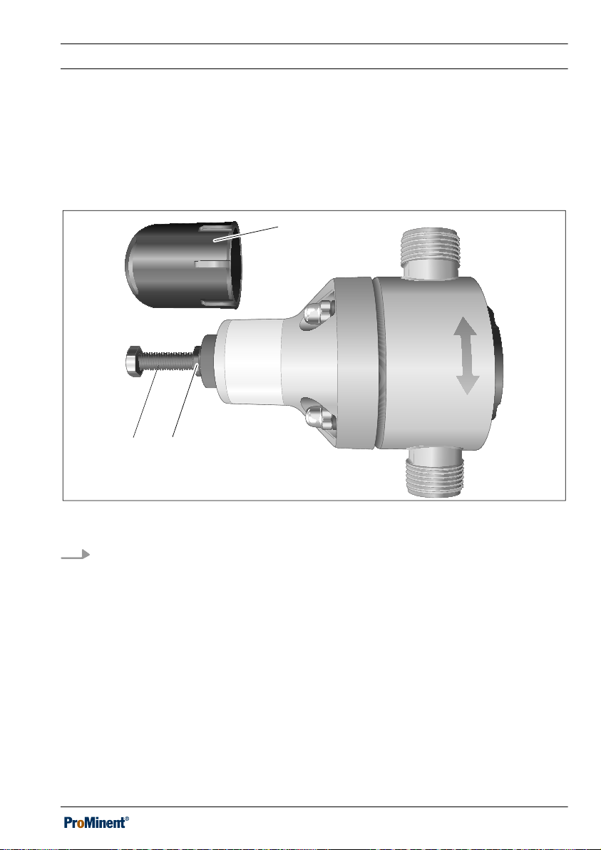
Fig. 4: Relieving pressure
Remove the cap (11). Loosen the locking nut (14) and unscrew the adjusting
screw (13).
The pressure now drops through the relief outlet.
ð
21
Page 22

Safety chapter
2.4 Intended use
n The relief valve DHV-UR is only
intended for use with liquids.
n When used correctly as a relief valve,
the relief valve DHV-UR limits the
operating pressure of the pumps and
protects pumps from overpressure
caused by operational faults or block‐
ages.
n The properties of the relief valve
DHV-UR can only be guaranteed
when used in conjunction with ProMi‐
nent pumps.
n All other uses or modifications are
prohibited.
22
Page 23

3 Storage and transport
User qualification: instructed user,
Ä Chapter 2.2 ‘User qualification’
on page 17
Original packaging
Damage to the product.
–
Transport, ship and store the
device in its original pack‐
aging.
–
Retain the packaging.
–
Please refer to the disposal
instructions should you need
to dispose of the packaging,
Ä Chapter 3.3 ‘Packaging
material’ on page 23
3.1 Storage
Permissible ambient temperature: +5
°C ... +50 °C.
Humidity: maximum 90% relative air
humidity, non-condensing.
Other ambient conditions: No dust, no
direct sunlight.
Storage and transport
3.3 Packaging material
Dispose of packaging material in an envi‐
ronmentally responsible way. All pack‐
aging components carry the corre‐
sponding recycling code
.
3.2 Transport
The sensor should be transported in its
original packaging and in compliance with
the permissible environmental conditions.
No further special conditions have to be
observed in relation to transport.
23
Page 24

Assembly
4 Assembly
4.1 Assembling the relief valve
n User qualification: trained qualified personnel,
on page 17
CAUTION!
Serious damage to the feeder assembly, relief line or pump is possible
The relief pipe for the relief valve must:
– Have an internal diameter greater than or equal to the internal diameter of the
relief outlet on the DHV-UR.
– End in an open or ventilated dosing tank.
– End above the maximum fill level of the dosing tank.
– Uninterruptedly run through the shut-off devices.
The relief valve can be installed in any fitting position.
Ä Chapter 2.2 ‘User qualification’
24
Page 25
A2550
1
Assembly
Fig. 5: The label [Entlastungsausgang/relief outlet] indicates the relief outlet (1).
If the relief line is pointing upwards, you will need to take appropriate measures,
for instance by installing a shut-off valve, to ensure that a filled relief line can be disman‐
tled.
25
Page 26
P_MOZ_0077_SW
Assembly
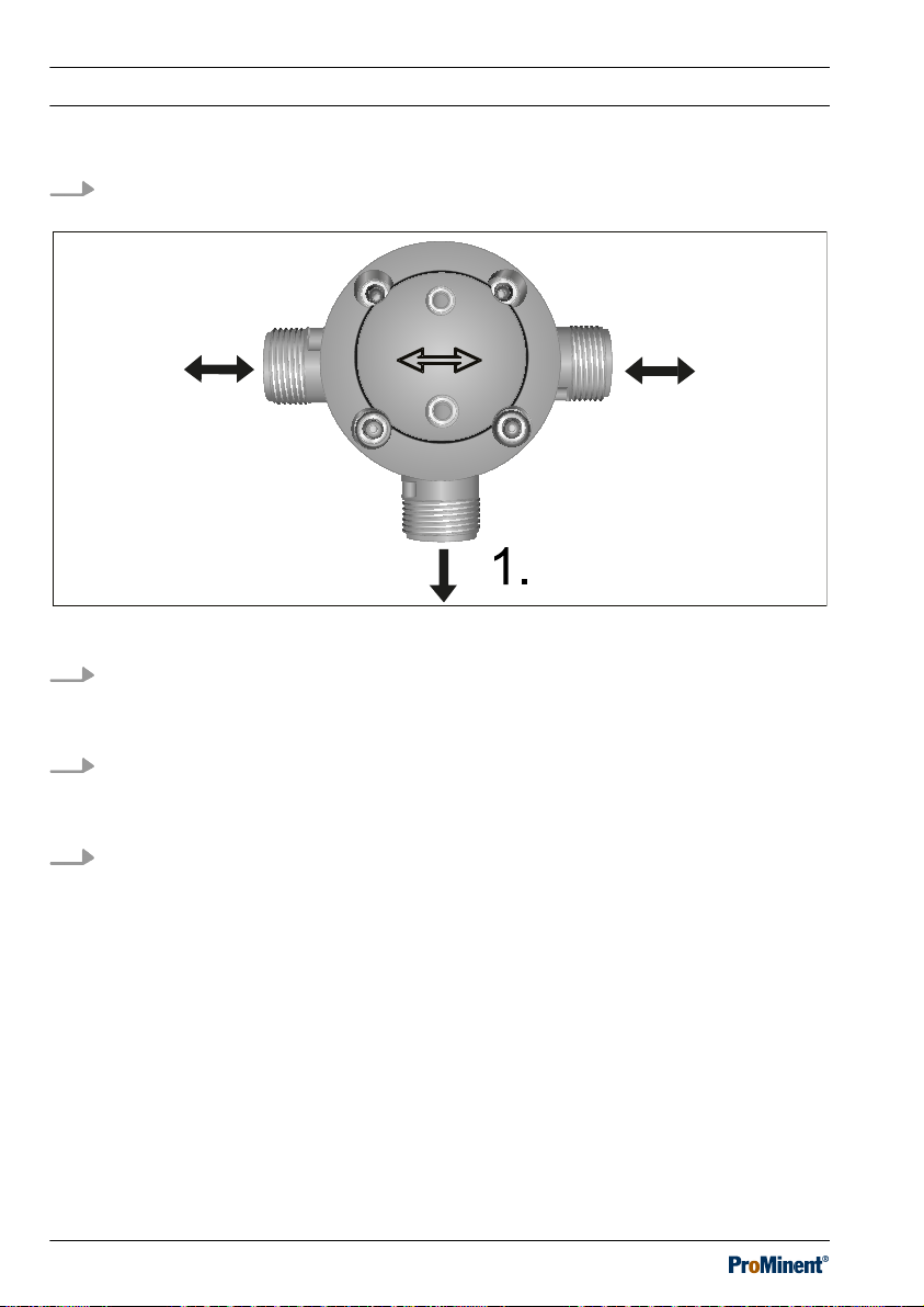
1. Prior to installation, remove water from the relief valve if it is to be used together
with media that may not come into contact with water.
Fig. 6: Directions of flow
2. Insert the relief valve into the pipework so that the directional arrows on the
housing of the relief valve point in the direction of flow.
The label
[Entlastungsausgang/relief outlet]
indicates the relief outlet (1).
3. Fit the relief valve so that it is not under mechanical tension, which could be
caused, among other things, by the pipework system.
Fit pipe compensators if required.
4. Tighten the threaded connectors.
26
Page 27
A2541
Assembly
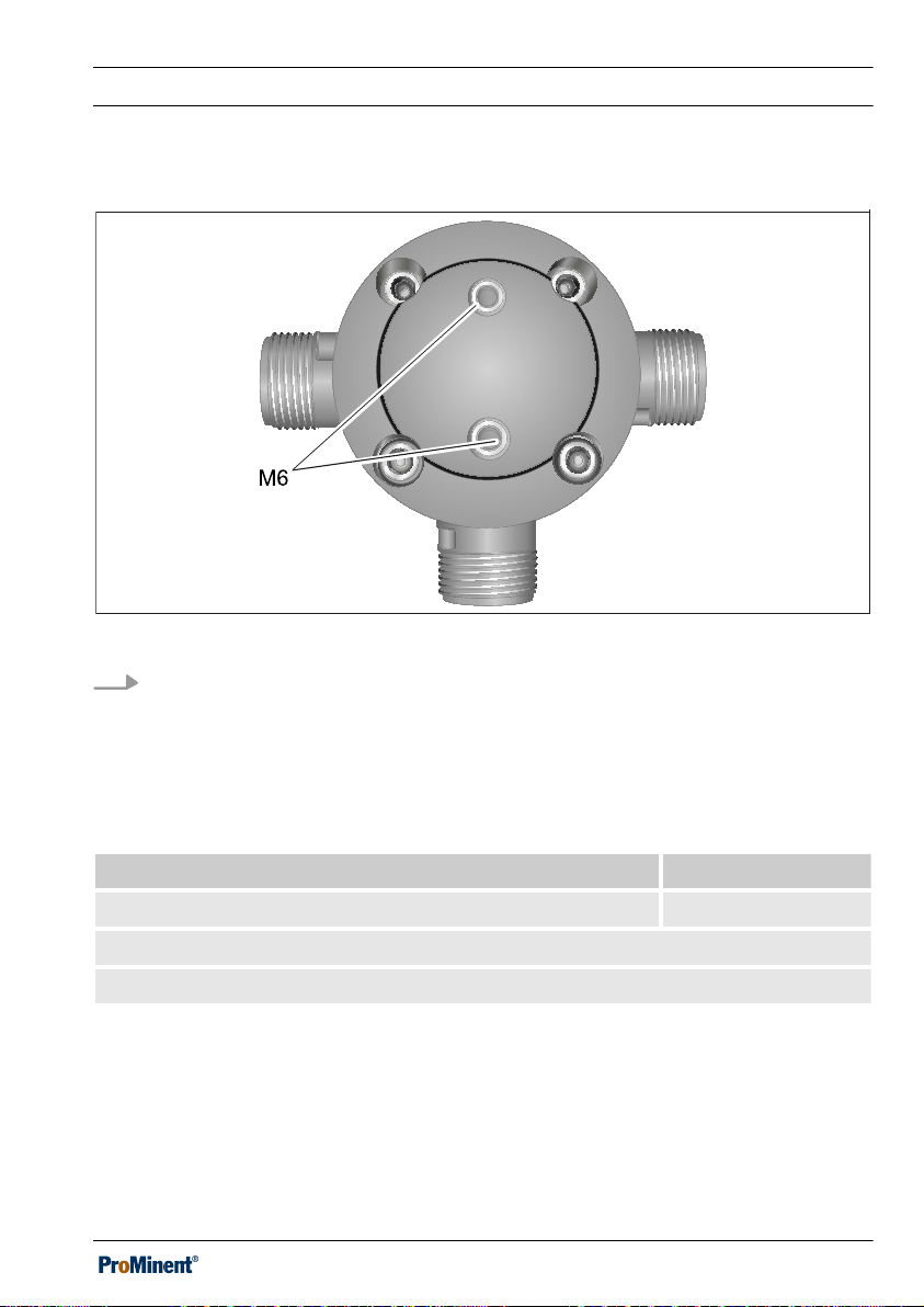
Optional: Installation on a mounting plate
Fig. 7: Holes for fixing bolts
5. 2 holes for M6 fixing bolts are located on the underside of the valve housing for
fixing it to a mounting plate.
Tightening torque for housing screws
Screw connection Value
Housing screws* DN10 / DN15 / DN20 / DN25 6 Nm
* greased
Check the tightening torque of the housing screws after 24 hours of operation.
27
Page 28
PD
P_MOZ_0061_SW
2.
1.
Assembly
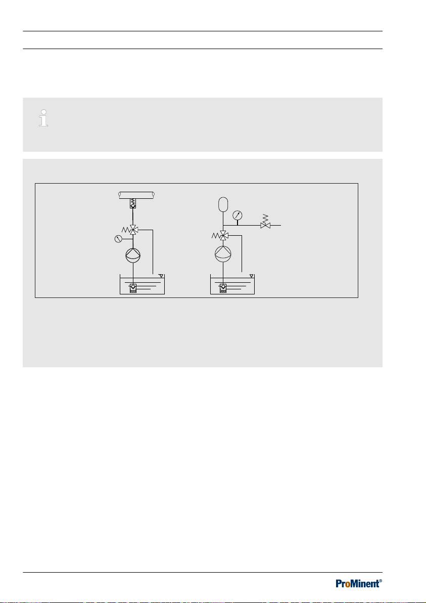
4.1.1 Installation examples
Read the operating instructions for your pump.
Installation examples
Fig. 8: Installation examples
1. - Use as a relief valve in the discharge line to protect the pump from
unauthorised over pressure
2. - Use together with a pulse damper to provide low-pulse metering
28
Page 29
Assembly
4.2 Fitting a manometer (optional)
Only with relief valve DHV-UR M (with manometer connection):
1. Screw the manometer into the hole in the housing of the relief valve using the flat
seal supplied in the packaging of the relief valve.
2. Check, when running, whether the connection between the valve body and the
manometer is tight.
Tab. 5: Maximum tightening torque of the screw connection.
Screw connection Value
Manometer 3 Nm
Plug 3 Nm
Store the plug supplied with its seal. You will need the plug if you dismantle the manom‐
eter.
29
Page 30
A2545
1
Commissioning
5 Commissioning
n User qualification: trained qualified personnel,
on page 17
CAUTION!
As supplied, the relief valve is set to 0 bar.
As the relief valve has not yet been set, there is a risk of hazardous situations
occurring when starting up the system or opening the shut-off devices, as the
relief valve is not yet capable of releasing impermissible overpressure.
– Take the necessary precautions.
– Refer to the material safety data sheet for the feed chemical.
– Please refer to the information on the nameplate (1).
Ä Chapter 2.2 ‘User qualification’
Fig. 9: Information on the nameplate (1).
30
Page 31

5.1 Pressure/temperature diagram
PVC-U
PP
PVDF, SS
10
9
8
7
6
5
4
3
2
1
-50 - 40 0-30 -20 -10 403010 5020 60 70 80 90 100 110
P [bar]
T [°C]
P_MAZ_0038_SW
Commissioning
Fig. 10: Pressure/temperature diagram
P Pressure in bar
T Temperature in °C
The pressure and temperature of your feed chemical must be below the corresponding
curve for the material of your relief valve.
The pressure/temperature diagram provides guideline values for the pressure and tem‐
perature resistance of the different material versions.
31
Page 32

A2544
11
14
13
Commissioning
5.2 Initial commissioning
1. Remove the cap (11).
2. Loosen the locking nut (14) and screw the adjusting screw (13) into the relief valve
as far as the stop.
3. Unscrew the adjusting screw (13) from the relief valve and tighten the locking nut
(14).
The relief valve is now activated.
ð
4. Replace the cap (11).
Fig. 11: Initial commissioning / Pressure relief
32
Page 33

5.3 Releasing pressure from the relief valve
1. Remove the cap (11).
2. Loosen the locking nut (14) and
unscrew the adjusting screw (13)
until the setting screw moves easily.
The pressure now drops
ð
through the relief outlet.
3. Subsequently reset the setting
pressure,
on page 34
Ä Further information
Commissioning
33
Page 34

Commissioning
5.4 Setting the relief valve
Set the relief valve under the same operating conditions as it will be subsequently used.
Never set the relief valve on a test rig and then install it in a system. Consider also the
viscosity of the feed chemical.
System components can burst if the pressure is set too high.
The set pressure PE at the relief valve should always be at least 1 bar lower than the
maximum permissible operating pressure PN of system components, such as the pulsa‐
tion damper, pump and piping system etc.
The set pressure PE at the relief valve must always be greater than the priming
pressure PV plus the differential pressure ΔP caused by mass deceleration.
PE > PV + ΔP
The priming pressure PV caused by the height h is:
PV = h x ρ where
PV is in bar, h in cm and ρ in kg/cm
ΔP is approx. 1.5 bar for standard piping up to approx. 3 m in length.
3
34
Page 35

A2544
11
14
13
Commissioning
Fig. 12: Setting the relief valve
Install a manometer in the discharge line or on the relief valve to set the adjustment pres‐
sure (e.g. 7 bar) more precisely.
1. Remove the cap (11).
2. Loosen the locking nut (14) and unscrew the adjusting screw (13) until the setting
screw moves easily.
3. Open the shut-off devices in the discharge line.
4. Switch on the metering pump.
5. Set the pressure as follows:
a. Fully screw in the adjusting screw (13) of the relief valve slowly.
b. Slowly screw in the adjusting screw of the back pressure valve in your installa‐
tion until the target operating pressure of +10% (e.g. 7.7 bar) is reached – and no
further!
c. Check whether the relief valve is correctly set at this pressure:
The setting is correct if feed chemical starts to drip out of the relief outlet.
n
n If no feed chemical drips out of the relief outlet, slowly open the adjusting
screw (13) until feed chemical starts to drip at the relief outlet – the setting is
then correct.
35
Page 36

Commissioning
n If feed chemical flows out of the relief outlet, slowly close the adjusting screw
(13) until no feed chemical escapes from the relief outlet.
Then check the operating pressure of the system (target operating pressure
+10% e.g 7.7 bar) at the manometer and adjust at the back pressure valve if
necessary.
Slowly open the adjusting screw (13) until feed chemical starts to drip out of
the relief outlet – the setting is then correct.
Please contact the manufacturer of the relief valve if you have unsuccessfully
performed this point in the setting instructions for the second time.
5.5 Setting the process pressure
1. Slowly unscrew the adjusting screw
of the back pressure valve until
normal target operating pressure
(e.g. 7 bar) is reached.
2. Check whether the set target oper‐
ating pressure remains constant
and whether the system’s threaded
connectors remain leak-tight.
3. Check that the relief valve does not
drip out of the relief outlet at normal
target operating pressure.
4. Secure the adjusting screws (13) of
the relief valve and the back pres‐
sure valve by tightening the locking
nuts (14).
5. Replace the cap (11).
6. Only with relief valve DHV-UR M
(with manometer connection):
Check whether the manometer con‐
nection is tightly sealed.
36
Page 37

Maintenance
6 Maintenance
n User qualification: trained user
CAUTION!
Elastomer seals can swell.
Hydrocarbon-based grease and cleaning agents can cause elastomer seals to
swell.
– Do not treat elastomer seals with cleaning agents.
– Only grease elastomer seals using silicone-based greases.
You may need to shorten the required maintenance intervals depending on the feed
chemicals used and operating conditions. Please take this into account when producing
your internal maintenance schedule.
Interval Maintenance work
Ä Chapter 2.2 ‘User qualification’ on page 17
bi-annually Check the interior parts of the relief valve and replace if necessary,
especially the diaphragm and the plunger seal.
To do this dismantle the relief valve – see
Ä Chapter 7 ‘Repair’
on page 38
In the event of a leak, tighten the connections or the manometer
connection, and check the tightening torque of the housing screws.
every 2 years Replace the diaphragm.
Tightening torque for housing screws
Screw connection Value
Housing screws* DN10 / DN15 / DN20 / DN25 6 Nm
* greased
Check the tightening torque of the housing screws after 24 hours of operation.
37
Page 38

Repair
7 Repair
n User qualification: trained user
WARNING!
Only return the unit for repair in a cleaned state and flushed through.
Only send the unit together with a completed Declaration of Decontamination. The
Declaration of Decontamination constitutes an integral part of an inspection /
repair order. We can only inspect or repair a unit if a Declaration of Decontamina‐
tion is submitted that has been completed correctly and in full.
The "Declaration of Decontamination” form can be found at www.prominent.com.
CAUTION!
Elastomer seals can swell.
Hydrocarbon-based grease and cleaning agents can cause elastomer seals to
swell.
– Do not treat elastomer seals with cleaning agents.
– Only grease elastomer seals using silicone-based greases.
Ä Chapter 2.2 ‘User qualification’ on page 17
CAUTION!
Only FDA: Seals can contaminate the feed chemical
Seals made of non-FDA-certified material, which have not been professionally
cleaned, can contaminate the feed chemical.
– Only use the right ProMinent seals.
– Have the seals professionally cleaned before use.
38
Page 39

A2546
11
2
8
5
6
4
12,
17,
18.
7
1
3
10
Fig. 13: Overview of components.
1 Valve body
2 Spring dome
3 Separating disc
4 Thrust washer
5 Diaphragm
6 Pressure plate with steel ball
Repair
7 Spring collar
8 Compression spring
10 Plunger
11 Cap
12, 17, 18 Nuts, screws, washers
39
Page 40

Repair
7.1 Dismantling the relief valve
1. Ensure that the pipework is at atmospheric pressure and drain the pipework.
2. Dismantle the relief valve.
3. Drain the relief valve and use a suitable medium to flush through the relief valve,
referring to the material safety data sheet for your feed chemical.
4. Position the relief valve upright.
5. Remove the cap (11).
6. Loosen the locking nut (14) and the adjusting screw (13) until the pressure on the
compression spring (8) has been fully released.
When the compression spring has been depressurised, the adjusting screw
ð
(13) can be easily turned.
7. Loosen the housing screws (12) and remove them.
8. Remove the spring dome (2).
9. Remove the following from the spring dome (2): the thrust washer (4), spring collar
(7), diaphragm (5), spring (8) and pressure plate (6) with the steel ball (9).
40
Page 41

Dismantling the plunger
A2554
1
10
3
Repair
Fig. 14: Dismantling the plunger
10. Remove the following from the valve body (1): the separating disc (3) and the com‐
plete plunger (10). To do so, lever the separating disc carefully out of the valve
body.
41
Page 42

3990
P_MOZ_0068_SW
1
19
18
20
17
16
15
14
13
12
11
10
9
8
7
6
5
4
3
2
Repair
Fig. 15: Cross-section through the DHV-UR PVC, PP, PVDF
42
Page 43

Replacing the plunger seal (16):
A2555
10.1
16
10.2
Repair
Fig. 16: Dismantling the plunger seal (16)
1. Clamp or fix the plunger to the plunger head (10.1) without damaging it.
2. Unscrew the plunger guide (10.2).
3. Remove the plunger seal (16).
43
Page 44

E
n
t
l
a
s
t
u
n
g
s
a
u
s
g
a
n
g
r
e
l
i
e
f
o
u
t
l
e
t
A2556
10.1 16
10.2
3
1
Repair
Fig. 17: Cleaning and checking all components.
4. Cleaning and checking all components.
5. Insert a new plunger seal (16) into the plunger head (10.1).
6.
Screw in the plunger guide (10.2), tightening torque
plunger guide on the plunger head’ on page 44
Tab. 6: Tightening torque: plunger guide on the plunger head
Screw connection Value
Ä Tab. 6 ‘Tightening torque:
.
Plunger guide on plunger head DN10 / DN15 3 Nm
Plunger guide on plunger head DN20 / DN25 4 Nm
44
Page 45

P_MOZ_0067_SW
3989
1
20
19
18
17
16
15
14
13
12
11
10
9
8
7
6
5
4
3
2
Repair
7.2 Inspecting and replacing the parts
Fig. 18: Cross-section through the DHV-UR SS
45
Page 46

Repair
1. Examine whether the diaphragm (5) and the connector seals (15) have any
obvious changes.
Replace the diaphragm, when required, and always the connection seals.
ð
2. Check the spring (8) for wear.
3. Check the plunger guide hole, plunger seat sealing surface, diaphragm contact
surface and O-ring groove on the valve body (1) for damage, dirt or lime scale.
CAUTION!
The relief valve can fail
Damaged sealing elements can lead to a loss of function and leakage of
the relief valve.
Always replace the sealing elements removed.
46
Page 47

7.3 Assembling the relief valve
1. Assemble the following into the
valve body (1): the complete
plunger (10) and separating disc
(3).
2. Assemble the following into the
spring dome (2): the thrust washer
(4), spring collar (7), spring (8), dia‐
phragm (5) and pressure plate (6)
with the steel ball (9).
3. Place the spring dome (2) onto the
housing.
4. Insert the housing screws (12) and
tighten the housing screws,
Ä ‘Tightening torque for housing
screws’ on page 48
5. Screw in the adjusting screw until
the adjusting screw becomes a little
harder to turn and tighten the
locking nut (14).
6. Replace the cap (11) onto the relief
valve.
7. Refit the relief valve.
Correctly reset the relief valve
ð
after fitting,
tion on page 34
.
Ä Further informa‐
.
Repair
47
Page 48

Repair
Tightening torque for housing screws
Screw connection Value
Housing screws* DN10 / DN15 / DN20 / DN25 6 Nm
* greased
Check the tightening torque of the housing screws after 24 hours of operation.
48
Page 49

Troubleshooting
8 Troubleshooting
n User qualification: trained user
WARNING!
With FDA only: Feed chemical can be physiologically contaminated
Non-FDA-certified parts will also become wetted in the event of a diaphragm rup‐
ture.
– Secure your entire process to prevent dangers with FDA versions.
Ä Chapter 2.2 ‘User qualification’ on page 17
For the position numbers – see Figure
Ä Chapter 7 ‘Repair’ on page 38
Fault description Cause Remedy
Pressure falls below the set
value.
Plunger seal (16) dirty. Clean the plunger seal
(16), see "Repair".
Plunger seal (16)
faulty.
Plunger seat in the
housing is dirty.
Plunger seat in the
Replace the plunger seal
(16), see "Repair".
Clean the plunger seat,
see "Repair".
Contact ProMinent.
housing is faulty.
Diaphragm (5) dirty. Clean the diaphragm (5),
see "Repair".
Diaphragm (5) faulty. Replace the diaphragm
(5), see "Repair".
Set pressure cannot be reached. Relief valve is installed
incorrectly.
Observe the direction
arrows and “Relief outlet”
label.
Pressure rises above the per‐
mitted value but the relief valve
does not properly depressurise.
The plunger guide is
sticking, possibly
because of dirt.
The valve is set to too
high an opening pres‐
Dismantle the valve and
clean, referring to
"Repair".
Set the valve to a lower
opening pressure.
sure.
49
Page 50

Troubleshooting
Fault description Cause Remedy
Pressure rises above the per‐
mitted value but the relief valve
does not properly depressurise.
The plunger guide
sticks due to too high a
media temperature.
Lower the media tem‐
perature in accordance
with the pressure-tem‐
perature diagram.
Leakage at the level of the dia‐
phragm (5).
Leakage at the adjusting screw
(13).
Contact pressure of the
diaphragm tensioner is
too low.
Tighten screws (12).
Tightening torque, see
"Repair".
Diaphragm (5) faulty. Replace the diaphragm
(5), see "Repair".
Loud noises when overflowing. Relief valve too small. Use a larger relief valve.
Type M only: Manometer display
"0" or remains at a constant
value.
Manometer faulty. Replace manometer*.
Manometer holes
Clean manometer holes.
blocked.
* If the manometer is faulty, remove the manometer and temporarily seal the hole with
the blanking plug – see
Ä Chapter 4 ‘Assembly’ on page 24
if operation without a man‐
ometer is permitted.
50
Page 51

Use Parts Disposal/Declaration of Decontamination
9 Use Parts Disposal/Declaration of Decontamination
n User qualification: instructed user,
see
Ä Chapter 2.2 ‘User qualification’
on page 17
WARNING!
Danger from hazardous sub‐
stances!
Possible consequence: Fatal or
very serious injuries.
Please ensure when handling haz‐
ardous substances that you have
read the latest safety data sheets
provided by the manufacture of the
hazardous substance. The actions
required are described in the
safety data sheet. Check the safety
data sheet regularly and replace, if
necessary, as the hazard potential
of a substance can be re-evaluated
at any time based on new findings.
The system operator is responsible
for ensuring that these safety data
sheets are available and that they
are kept up to date, as well as for
producing an associated hazard
assessment for the workstations
affected.
A completed and signed "Declara‐
tion of Decontamination" is
required by law and in order to pro‐
tect our staff, before your order can
be processed.
Ensure that the Declaration of
Decontamination is attached to the
outside of the package. Otherwise
we are unable to accept your
delivery.
NOTICE!
Regulations governing the disposal
of used parts
– Note the national regulations
and legal standards that cur‐
rently apply in your country
when disposing of the product.
ProMinent GmbH, Heidelberg/Germany
will take back clean used parts.
NOTICE!
The used part can only be
accepted with a completed Decla‐
ration of Decontamination
Printed copy also available as a
download at: www.prominent.com
51
Page 52

PVC-U
PP
PVDF, SS
10
9
8
7
6
5
4
3
2
1
-50 - 40 0-30 -20 -10 403010 5020 60 70 80 90 100 110
P [bar]
T [°C]
P_MAZ_0038_SW
Technical data
10 Technical data
The properties given for the relief valve DHV-UR can only be guaranteed when used in
connection with ProMinent® pumps.
Fig. 19: Pressure/temperature diagram
P Pressure in bar
T Temperature in °C
The pressure and temperature of your feed chemical must be below the corresponding
curve for the material of your relief valve.
The pressure-temperature diagram provides guideline values for the pressure and tem‐
perature resistance of the different material versions for feed chemicals to which the relief
valves are resistant.
52
Page 53

Technical data
Temperatures
Specification Value
Storage and transport temperature * -10 ... +50 °C
Ambient temperature in operation * -10 ... +45 °C
* Note the freezing temperature of the feed chemical to reliably prevent the relief valve
from being damaged.
Operating parameters
Parameter Value
Permissible rated pressure PN at +20°C10 bar
Operating pressure Pressure/temperature diagram Fig. 19
Setting range 0.5 ... 10 bar
Working pressure equal to set pressure + pressure loss – see
Ä ‘Diagrams for using the DHV-UR’
on page 55
Minimum opening pressure, approx. 0.5 bar
Approx. difference between opening
0.3 bar
and closing pressure
Maximum flow Q
53
max
Ä ‘Maximum flow Q
’ on page 54
max
Page 54

Technical data
Maximum flow Q
A) The following values are only applicable to Q
max
when using metering pumps with
max
properly dimensioned pulsation dampers or with constant flow velocity:
Valve type DHV-UR Q
for H2O at 20 °C
max
DN 10 500 l/h
DN 15 890 l/h
DN 20 1000 l/h
DN 25 1300 l/h
B) The following applies to the flow Qu when operating metering pumps without a pulsa‐
tion damper:
For solenoid metering pump: Qu = Q
For motor-driven metering pumps: Qu = Q
max
/20
max
/3
54
Page 55

0
0,5
1
1,5
2
2,5
3
3,5
4
4,5
5
0,0 0,2 0,4 0,6 0,8 1,0 1,2 1,4 1,6 1,8 2,0
P [bar]
Q [m3/h]
DN 10
DN 15
DN 20
DN 25
0
0,5
1
1,5
2
2,5
3
3,5
4
4,5
5
0,2 0,4 0,6 0,8 1,0 1,2 1,4 1,6 1,8 2,0 2,2 2,4 2,6
ΔP [bar]
Q [m3/h]
2,8 3,0 3,2 3,4 3,6
DN 10
DN 15
DN 20
DN 25
Technical data
Diagrams for using the DHV-UR
Fig. 20: Opening pressure curve with overflow for DHV-UR – with water at 20°C and a
constant flow velocity. P: Working pressure / Q: Flow, set to 1 bar
Fig. 21: Pressure drop curves with overflow with fully opened valve for DHV-UR – with
water at 20°C and a constant flow velocity. ΔP: Pressure difference/Q: Flow
55
Page 56

0,0
0,1
0,2
0,3
0,4
0,5
0,6
0,7
0,8
0,9
1,0
0,5
∆p [bar]
1,0 1,5 2,0 2,5 3,0 3,5 4,0 4,5
Q [m³/h]
DN 10 - 15
DN 20 - 25
Technical data
Fig. 22: Pressure drop curves for the main line (valve closed) without overflow for DHVUR – with water at 20°C and a constant flow velocity. ΔP: Pressure difference/Q: Flow
Tab. 7: Kv values* for the main line without overflow (the relief line is 100% closed):
DHV-UR Kv
DN10 ... 15 4.5 m³/h
DN20 ... 25 13 m³/h
* The Kv values correspond to the water flow through a valve with a pressure difference
of 1 bar
56
Page 57

Technical data
Material specifications
All wetted materials in the "Physiologically safe (FDA) in respect of wetted materials"
design comply with the FDA guidelines in line with the certificate supplied.
For the position numbers - see
Ä Chapter 12 ‘Exploded view drawing’ on page 62
Tab. 8: Material specifications for the PPE, PPB and PCE versions
Pos. Description PPE PPB PCE
1.19 Valve housing PP PVC-U
2 Spring dome PP + 30% GF
3 Separating disc PP PVC-U
4 Thrust washer POM
5 Diaphragm EPDM / PTFE, laminated
6 Pressure plate Steel, nickel plated
7 Spring collar POM
8 Compression spring Steel, galvanised
9 Ball 1.3541
10 Plunger PP* PVC-U*
11 Protective cap PE
15 Seal EPDM FKM EPDM
16 Plunger seal EPDM FKM EPDM
20 O-ring EPDM FKM EPDM
21** Plug PP PP PVC-U
22** Seal for a manometer PTFE, natural
Various Housing screws, nuts, washers V2A
FKM = fluorine rubber
* or high quality PVDF / ** not shown
57
Page 58

Technical data
Tab. 9: Material specifications for the PCB, PVT and SST versions
Pos. Description PCB PVT SST
1.19 Valve housing PVC-U PVDF 1.4404
2 Spring dome PP + 30% GF
3 Separating disc PVC-U PVDF 1.4404
4 Thrust washer POM
5 Diaphragm EPDM / PTFE, laminated
6 Pressure plate Steel, nickel plated
7 Spring collar POM
8 Compression spring Steel, galvanised
9 Ball 1.3541
10 Plunger PVC-U PVDF PTFE, nat‐
ural
11 Protective cap PE
15 Seal FKM PTFE**
16 Plunger seal FKM PTFE*
20 O-ring FKM PTFE, nat‐
ural
21*** Plug PVC-U PVDF -
22*** Seal for a manometer PTFE, natural -
Various Housing screws, nuts, washers V2A
FKM = fluorine rubber
*. PTFE / FKM cover ring
** PTFE / EPDM shaped composite seal
*** not shown
58
Page 59

Technical data
Combination options
The relief valve / metering pump combination options are limited by the maximum flow
Q
of the relief valve.
max
The universal relief valve DHV-UR can essentially be used with metering pumps in the
low pressure range, taking into consideration pressure, feed chemical and flow.
Tab. 10: Assignment of the relief valves to the corresponding ProMinent® pump types
DHV-UR Pump type
DN 10 alpha, Beta, DLTa, GMX_, Pneumados, Vario DN 10, Hydro DN 10,
EXtronic DN10
DN 15 Vario DN15, Sigma DN15, Hydro DN15
DN 20 Sigma DN20, Meta DN20, Makro TZ DN20
DN 25 Sigma DN25/DN32, Hydro DN25/DN32, Meta DN25,
Makro TZ DN 25/DN32
10.1 Applied standards
EN 12266-1:2012
EN ISO 16138:2006
59
Page 60

A2542
DHV-UR spare parts
11 DHV-UR spare parts
Spare parts kits
Ordering address for spare parts and accessories: The current address for ordering
spare parts and accessories can be found on the homepage of the manufacturer ProMi‐
nent.
Fig. 23: Example: Spare parts kit for DHV-U, -UR DN10/15, 1078732
Contents:
n O-ring, external
n Diaphragm
n Plunger seal
n Seal, blanking plug
60
Page 61

DHV-UR spare parts
Spare parts kit Material design Order no.
DHV-U, -UR DN10/15 EPDM 1078732
DHV-U, -UR DN10/15 FKM 1078733
DHV-U, -UR DN10/15 PTFE 1078734
DHV-U, -UR DN20/25 EPDM 1078735
DHV-U, -UR DN20/25 FKM 1078736
DHV-U, -UR DN20/25 PTFE 1078737
DHV-U DN32/40 EPDM 1078784
Plug
The plug is used to seal the manometer connection.
Description Order no.
Plug for PP_ 1077791
Plug for PC_ 1077792
Plug for PV_ 1077793
61
Page 62

P_MOZ_0072_SW
3985_2
1
18
17
16
15
14
13
12
11
10
9
8
7
6
5
4
3
2
18
10.2
10.1
Exploded view drawing
12 Exploded view drawing
12.1 Exploded view drawing of DHV-UR PP_, PC_, PV_
Fig. 24: Exploded view drawing of DHV-UR PP_, PC_, PV_
62
Page 63

12.2 Exploded view drawing of DHV-UR SS
P_MOZ_0073_SW
3986
1
18
17
16
15
14
13
12
11
10.2
10.1
10
9
8
7
6
5
4
3
2
Exploded view drawing
Fig. 25: Exploded view drawing of DHV-UR SS
63
Page 64

Exploded view drawing
12.3 Parts list
Position Description
1 Valve housing
2 Spring dome
3 Separating disc
4 Thrust washer
5 Diaphragm
6 Pressure plate
7 Spring collar
8 Compression spring
9 Ball
10 (1/2) Plunger
11 Protective cap
12 Housing screws
13 Adjusting screw
14 Locking nut
15 Seal
16 Plunger seal
17 Nuts
18 Washers
64
Page 65

13 Dimensional drawing
63_03-101_00_49-7a
P_MOZ_063_SW
m
G 1/4“
12.5
A
D
A
L
G
d
DN
h
max. H
L/2
B
A
A
13.1 Dimensional drawing of DHV-UR PVC, PP, PVDF
Dimensional drawing
Fig. 26: Dimensional drawing of DHV-UR PVC-U, PP, PVDF - dimensions in mm
* connector for a manometer.
Union nut and insert are not supplied in the scope of delivery.
65
Page 66

Dimensional drawing
DN10 DN15 DN20 DN25
d 16 20 25 32
DN (mm) 10 15 20 25
DN (inches) 3/8 1/2 3/4 1
T G 3/4 G 1 G 1 1/4 G 1 1/2
B 35 35 46 46
D 79 79 99 99
h 24 24 37 37
H 144 144 196 196
L 118 118 150 150
m M6 M6 M6 M6
66
Page 67

13.2 Dimensional drawing of DHV-UR SS
63_03-101_00_52-7a
P_MOZ_064_SW
m
A
A
D
G
d
DN
max. H
L
h
L1
+1,0
L
1
/2
L/2
AA
Dimensional drawing
Fig. 27: Dimensional drawing of DHV-UR SS - dimensions in mm
Union nut and insert are not supplied in the scope of delivery.
67
Page 68

Dimensional drawing
DN10 DN15 DN20 DN25
d 16 20 25 32
DN (mm) 10 15 20 25
DN (inches) 3/8 1/2 3/4 1
T G 3/4 G 1 G 1 1/4 G 1 1/2
B 35 35 46 46
D 79 79 99 99
H 144 144 196 196
h 20 20 30 30
L 116 116 148 148
L1 118 118 150 150
m M6 M6 M6 M6
68
Page 69

14 Index
1, 2, 3 ...
“M” version .................... 9
A
Action, step by step .............. 5
Address, nameplate ............. 10
Adhesive labels ................ 15
Air humidity ................... 23
Ambient temperature in operation ....53
Assembling the relief valve ........ 47
Assigning relief valves ........... 59
C
Combination options .............59
Configuration for manometer ....... 13
D
Date, nameplate ................10
Declaration of Decontamination ..... 38
Decontamination declaration ....... 51
Diagrams for using the DHV-UR .....55
Dimensional drawing ............ 65
Dismantling the plunger .......... 42
Dismantling the relief valve ........ 40
Disposal ..................... 51
E
Error ........................49
F
Faults ....................... 49
FDA guidelines ................ 12
Index
FDA version ................... 9
Fitting position ................. 25
Flow volume of the connected pump ..20
Functional mode ................ 9
G
General non-discriminatory approach .. 5
I
Information in the event of an emer‐
gency ....................... 21
Initial commissioning .............32
Inspecting and replacing the parts ... 45
Installation on a mounting plate ..... 27
Intended use .................. 22
K
Kv values .................... 56
L
Labels for fluid connections ........ 15
Links to elements or sections of these
instructions or other applicable docu‐
ments ........................ 5
M
Manometer .................... 9
Manometer connector ............ 29
Material specifications ............57
Maximum flow Q
More symbols .................. 5
Mounting plate ................. 27
............. 54
max
69
Page 70

Index
N
Nominal width ............ 11, 12, 13
Non-discriminatory approach ........ 5
O
Operating parameters ............ 53
Original packaging .............. 23
Other ambient conditions ..........23
Overview of components ..........39
P
P-T diagram .................. 52
Permissible ambient temperature .... 23
Plug with seal ................. 29
Pressure/temperature diagram ... 31, 52
R
Recycling .................... 23
Regulations governing the disposal of
used parts .................... 51
Releasing pressure from the relief
valve ....................... 33
Relief outlet ................... 15
Relieving pressure .............. 21
Replacing the plunger seal ........ 43
S
Safety information .............. 19
Scope of delivery ................ 9
Setting the process pressure ....... 36
Setting the relief valve ............34
Setting, process pressure ......... 36
Signs ....................... 15
Standards .................... 59
T
Temperatures ................. 53
Thread in inches .......... 11, 12, 13
Tightening torque ............... 44
Tightening torque of the screw con‐
nection ...................... 29
U
User qualification ............... 17
W
Warning information ............. 15
70
Page 71

ProMinent GmbH
Im Schuhmachergewann 5-11
69123 Heidelberg, Germany
Germany
Telephone: +49 6221 842-0
Fax: +49 6221 842-419
Email: info@prominent.com
Internet: www.prominent.com
983439, 3, en_GB
© 2018
Page 72

Montage- und Betriebsanleitung
A2543
Universelles Überströmventil
DHV-UR
DE
Betriebsanleitung bitte zuerst vollständig durchlesen. · Nicht wegwerfen.
Bei Schäden durch Installations- oder Bedienfehler haftet der Betreiber.
Die neueste Version einer Betriebsanleitung ist auf unserer Homepage verfügbar.
Zielgruppe: geschulter AnwenderTeilenummer 983439 Version: BA MOZ 042 03/18 DE
Page 73

Ergänzende Anweisungen
Allgemeine Gleichbehandlung Dieses Dokument verwendet die nach der
Grammatik männliche Form in einem
neutralen Sinn, um den Text leichter
lesbar zu halten. Es spricht immer Frauen
und Männer in gleicher Weise an. Die
Leserinnen bitten wir um Verständnis für
diese Vereinfachung im Text.
Ergänzende Anweisungen
Lesen Sie bitte die ergänzenden Anweisungen durch.
Infos
Eine Info gibt wichtige Hinweise für das richtige Funktionieren des Geräts oder
soll Ihre Arbeit erleichtern.
Warnhinweise
Warnhinweise sind mit ausführlichen Beschreibungen der Gefährdungssituation ver‐
sehen, siehe
Ä Kapitel 2.1 „Kennzeichnung der Warnhinweise“ auf Seite 83
.
Zur Hervorhebung von Handlungsanweisungen, Verweisen, Auflistungen, Ergebnissen
und anderen Elementen können in diesem Dokument folgende Kennzeichnungen ver‐
wendet werden:
Tab. 1: Weitere Kennzeichnung
Kennzeichen Beschreibung
Handlung Schritt-für-Schritt.
⇨ Ergebnis einer Handlung.
Links auf Elemente bzw. Abschnitte dieser Anleitung oder mitgel‐
tende Dokumente.
n
[Taster]
Auflistung ohne festgelegte Reihenfolge.
Anzeigeelemente (z. B. Signalleuchten).
Bedienelemente (z. B. Taster, Schalter).
73
Page 74

Ergänzende Anweisungen
Kennzeichen Beschreibung
„Anzeige/GUI“
CODE
Bildschirmelemente (z. B. Schaltflächen, Belegung von Funktions‐
tasten).
Darstellung von Softwareelementen bzw. Texten.
74
Page 75

Inhaltsverzeichnis
Inhaltsverzeichnis
1 Über dieses Produkt............................................................................................. 77
1.1 Typenschild.................................................................................................. 78
1.2 Ausführungen............................................................................................... 79
1.2.1 Ausführung der Standardversion............................................................... 79
1.2.2 Ausführung mit FDA-Freigabe................................................................... 80
1.2.3 Ausführung mit Manometervorbereitung................................................... 81
2 Sicherheitskapitel.................................................................................................. 83
2.1 Kennzeichnung der Warnhinweise............................................................... 83
2.2 Benutzer-Qualifikation.................................................................................. 85
2.3 Allgemeine Sicherheitshinweise................................................................... 87
2.3.1 Angaben für den Notfall............................................................................. 89
2.4 Bestimmungsgemäße Verwendung............................................................. 90
3 Lagern und transportieren ................................................................................... 91
3.1 Lagern.......................................................................................................... 91
3.2 Transport...................................................................................................... 91
3.3 Verpackungsmaterial.................................................................................... 91
4 Montieren.............................................................................................................. 92
4.1 Das Überströmventil montieren.................................................................... 92
4.1.1 Installationsbeispiele................................................................................. 96
4.2 Ein Manometer montieren (Option).............................................................. 97
5 Inbetriebnahme..................................................................................................... 98
Druck-Temperatur-Diagramm...................................................................... 99
5.1
5.2 Erstinbetriebnahme.................................................................................... 100
5.3 Druckentlasten des Überströmventils......................................................... 101
5.4 Überströmventil einstellen.......................................................................... 102
5.5 Prozessdruck einstellen............................................................................. 104
6 Wartung.............................................................................................................. 105
7 Reparieren.......................................................................................................... 106
Überströmventil zerlegen .......................................................................... 108
7.1
7.2 Teile untersuchen und austauschen.......................................................... 113
7.3 Überströmventil zusammensetzen............................................................. 115
8 Funktionsstörungen beheben............................................................................. 117
75
Page 76

Inhaltsverzeichnis
9 Altteileentsorgung/Dekontaminationserklärung.................................................. 119
10 Technische Daten............................................................................................... 120
10.1 Angewandte Normen................................................................................ 127
11 Ersatzteile DHV-UR............................................................................................ 128
12 Explosionszeichnung.......................................................................................... 130
12.1 Explosionszeichnung DHV-UR PP_, PC_ und PV_ ................................. 130
12.2 Explosionszeichnung DHV-UR SS........................................................... 131
12.3 Stückliste.................................................................................................. 132
13 Maßblatt.............................................................................................................. 133
13.1 Maßblatt DHV-UR PVC-U, PP, PVDF ..................................................... 133
13.2 Maßblatt DHV-UR SS............................................................................... 135
14 Index................................................................................................................... 137
76
Page 77

A2538
Über dieses Produkt
1 Über dieses Produkt
Das Überströmventil schützt Pumpen vor unzulässigem Überdruck infolge von Betriebs‐
fehlern oder Blockierungen.
Das universelle Überströmventil Typ DHV-UR ist ein stufenlos einstellbares, innen ange‐
strömtes Kolben-Membranventil. Im Falle eines unzulässigen Überdrucks öffnet die
innenliegende Kolben-Membran die zweite Ausgangsleitung, den Entlastungsausgang.
Die Montage des Überströmventils ist an beliebiger Stelle des Rohrleitungssystems mög‐
lich. Aufgrund eines nahezu freien Rohrquerschnitts entsteht nur ein sehr geringer Druck‐
verlust.
Abb. 1: Lieferumfang: Überströmventil mit Dichtringen für den Anschluss.
An das Überströmventil DHV-UR in der Ausführung "M" kann zusätzlich ein Manometer
installiert werden.
Das Überströmventil gibt es auch als FDA-Version.
77
Page 78

A2539
Über dieses Produkt
1.1 Typenschild
Abb. 2: Typenschild
Das Typenschild gibt Ihnen Auskunft über:
n Hersteller mit Adresse und Telefonnummer
n Herstellungsort und -land,
n Herstellungsdatum in Woche / Jahr
n Typ des Gerätes mit Durchmesser und Materialausführung
n Teilenummer
n Seriennummer
n Druckbereich in bar und psi
n Anschlussgewinde in Zoll und Millimeter
n Werkstoffausführung
[Teile Nr. / part no.]
[Serien Nr. / serial no.]
[Druckbereich / pr. range]
[Material / material]
,
[Anschluss / connect]
.
[Typ / type]
,
,
78
Page 79

Über dieses Produkt
1.2 Ausführungen
1.2.1 Ausführung der Standardversion
Tab. 2: Ausführung: Standard
Ausführung Nennweite Gewinde in Zoll Bestell-Nummer
PPE DN 10 3/4 1061337
PPB DN 10 3/4 1061341
PCE DN 10 3/4 1061339
PCB DN 10 3/4 1061343
PVT DN 10 3/4 1061365
SST DN 10 3/4 1061550
PPE DN 15 1 1061336
PPB DN 15 1 1061340
PCE DN 15 1 1061338
PCB DN 15 1 1061342
PVT DN 15 1 1061364
SST DN 15 1 1061551
PPE DN 20 1 1/4 1061367
PPB DN 20 1 1/4 1061371
PCE DN 20 1 1/4 1061369
PCB DN 20 1 1/4 1061373
PVT DN 20 1 1/4 1061375
SST DN 20 1 1/4 1061569
PPE DN 25 1 1/2 1061366
PPB DN 25 1 1/2 1061370
PCE DN 25 1 1/2 1061368
PCB DN 25 1 1/2 1061372
79
Page 80

Über dieses Produkt
Ausführung Nennweite Gewinde in Zoll Bestell-Nummer
PVT DN 25 1 1/2 1061374
SST DN 25 1 1/2 1061570
1.2.2 Ausführung mit FDA-Freigabe
Tab. 3: Ausführung: FDA
Ausführung Nennweite Gewinde in Zoll Bestell-Nummer
PPE DN 10 3/4 1075828
PVT DN 10 3/4 1075830
SST DN 10 3/4 1075847
PPE DN 15 1 1075827
PVT DN 15 1 1075829
SST DN 15 1 1075846
PPE DN 20 1 1/4 1075833
PVT DN 20 1 1/4 1075845
SST DN 20 1 1/4 1075849
PPE DN 25 1 1/2 1075832
PVT DN 25 1 1/2 1075844
SST DN 25 1 1/2 1075848
Alle medienberührten Werkstoffe in der Ausführung „physiologisch unbedenklich (FDA)
bezüglich medienberührtem Werkstoff“ entsprechen den nachfolgenden FDA-Richtlinien:
FDA-Richtlinien für die Werkstoffe:
n PTFE: 21CFR177.1510,
n PVDF: 21CFR177.2510,
n PP: 21CFR177.1520,
n EPDM/FKM: 21CFR177.2600.
80
Page 81

Über dieses Produkt
1.2.3 Ausführung mit Manometervorbereitung
Das Überströmventil DHV-UR in der Ausführung M ist mit einer Gehäusebohrung für den
Manometereinbau vorbereitet. Hier können vom Kunden Manometer mit einem Gewinde‐
stutzen G 1/4“ (ISO 228) direkt montiert werden.
Tab. 4: Ausführung: Überströmventil Typ DHV-UR M mit Manometervorbereitung
Ausführung Nennweite Gewinde in Zoll Bestell-Nummer
PPE DN 10 3/4 1077221
PPB DN 10 3/4 1077259
PCE DN 10 3/4 1077255
PCB DN 10 3/4 1077263
PVT DN 10 3/4 1077267
PPE DN 15 1 1077220
PPB DN 15 1 1077258
PCE DN 15 1 1077254
PCB DN 15 1 1077262
PVT DN 15 1 1077266
PPE DN 20 1 1/4 1077219
PPB DN 20 1 1/4 1077257
PCE DN 20 1 1/4 1077223
PCB DN 20 1 1/4 1077261
PVT DN 20 1 1/4 1077265
PPE DN 25 1 1/2 1077218
PPB DN 25 1 1/2 1077256
PCE DN 25 1 1/2 1077222
PCB DN 25 1 1/2 1077260
PVT DN 25 1 1/2 1077264
81
Page 82

Über dieses Produkt
82
Page 83

A2540
Sicherheitskapitel
2 Sicherheitskapitel
Die an dem Gerät angebrachten Aufkleber und Schilder wie z. B.:
Abb. 3: Entlastungsausgang [Entlastungsausgang/relief outlet] / Durchflussrichtung
n Kennzeichen für Fluidanschlüsse,
n Durchflussrichtungspfeil,
n Typenschild,
müssen von Ihnen beachtet und in vollständig lesbarem Zustand gehalten werden.
2.1 Kennzeichnung der Warn‐
hinweise
Einleitung
Diese Betriebsanleitung beschreibt die
technischen Daten und Funktionen des
Produktes. Die Betriebsanleitung gibt aus‐
führliche Warnhinweise und ist in klare
Handlungsschritte aufgegliedert.
Warnhinweise und Hinweise gliedern sich
nach dem folgenden Schema. Hierbei
kommen verschiedene, der Situation
angepasste, Piktogramme zum Einsatz.
Die hier aufgeführten Piktogramme dienen
nur als Beispiel.
GEFAHR!
Art und Quelle der Gefahr
Folge: Tod oder schwerste Verlet‐
zungen.
Maßnahme, die ergriffen werden
muss, um diese Gefahr zu ver‐
meiden.
Beschriebene Gefahr
– Bezeichnet eine unmittelbar
drohende Gefahr. Wenn die
Situation nicht gemieden wird,
sind Tod oder schwerste Ver‐
letzungen die Folge.
83
Page 84

Sicherheitskapitel
WARNUNG!
Art und Quelle der Gefahr
Mögliche Folge: Tod oder
schwerste Verletzungen.
Maßnahme, die ergriffen werden
muss, um diese Gefahr zu ver‐
meiden.
– Bezeichnet eine möglicher‐
weise gefährliche Situation.
Wenn die Situation nicht
gemieden wird, können Tod
oder schwerste Verletzungen
die Folge sein.
VORSICHT!
Art und Quelle der Gefahr
Mögliche Folge: Leichte oder
geringfügige Verletzungen. Sach‐
beschädigung.
Maßnahme, die ergriffen werden
muss, um diese Gefahr zu ver‐
meiden.
– Bezeichnet eine möglicher‐
weise gefährliche Situation.
Wenn die Situation nicht
gemieden wird, können leichte
oder geringfügige Verlet‐
zungen die Folge sein. Darf
auch für Warnung vor Sach‐
schäden verwendet werden.
HINWEIS!
Art und Quelle der Gefahr
Schädigung des Produkts oder
seiner Umgebung.
Maßnahme, die ergriffen werden
muss, um diese Gefahr zu ver‐
meiden.
– Bezeichnet eine möglicher‐
weise schädliche Situation.
Wenn die Situation nicht
gemieden wird, kann das Pro‐
dukt oder etwas in seiner
Umgebung beschädigt
werden.
Art der Information
Anwendungstipps und Zusatzinfor‐
mation.
Quelle der Information. Zusätzliche
Maßnahmen.
–
Bezeichnen Anwendungstipps
und andere besonders nütz‐
liche Informationen. Es ist kein
Signalwort für eine gefährliche
oder schädliche Situation.
84
Page 85

Sicherheitskapitel
2.2 Benutzer-Qualifikation
WARNUNG!
Verletzungsgefahr bei unzureichender Qualifikation des Personals
Der Betreiber der Anlage/des Gerätes ist für die Einhaltung der Qualifikationen
verantwortlich.
Wenn unqualifiziertes Personal Arbeiten an dem Gerät vornimmt oder sich im
Gefahrenbereich des Gerätes aufhält, entstehen Gefahren, die schwere Verlet‐
zungen und Sachschäden verursachen können.
– Alle Tätigkeiten nur durch dafür qualifiziertes Personal durchführen lassen.
– Unqualifiziertes Personal von den Gefahrenbereichen fernhalten.
Die einschlägigen Unfallverhütungsvorschriften sowie die sonstigen allgemein
anerkannten sicherheitstechnischen Regeln einhalten.
Ausbildung Definition
unterwiesene Person Als unterwiesene Person gilt, wer über die übertragenen Auf‐
gaben und möglichen Gefahren bei unsachgemäßem Verhalten
unterrichtet und erforderlichenfalls angelernt, sowie über die
notwendigen Schutzeinrichtungen und Schutzmaßnahmen
belehrt wurde.
geschulter Anwender Als geschulter Anwender gilt, wer die Anforderungen an eine
unterwiesene Person erfüllt und zusätzlich eine anlagenspezifi‐
sche Schulung bei dem Hersteller oder einem autorisierten Ver‐
triebspartner erhalten hat.
ausgebildete Fach‐
kraft
Als ausgebildete Fachkraft gilt, wer aufgrund seiner Ausbildung,
Kenntnisse und Erfahrungen sowie Kenntnis der einschlägigen
Bestimmungen die ihm übertragenen Arbeiten beurteilen und
mögliche Gefahren erkennen kann. Eine ausgebildete Fach‐
kraft muss in der Lage sein, die ihr übertragenen Arbeiten unter
Zuhilfenahme von Zeichnungsdokumentation und Stücklisten
selbständig durchzuführen. Zur Beurteilung der fachlichen Aus‐
bildung kann auch eine mehrjährige Tätigkeit auf dem betreff‐
enden Arbeitsgebiet herangezogen werden.
85
Page 86

Sicherheitskapitel
Ausbildung Definition
Elektrofachkraft Die Elektrofachkraft ist aufgrund ihrer fachlichen Ausbildung,
Kenntnisse und Erfahrungen sowie Kenntnis der einschlägigen
Normen und Bestimmungen in der Lage, Arbeiten an elektri‐
schen Anlagen auszuführen und mögliche Gefahren selbst‐
ständig zu erkennen und zu vermeiden. Eine Elektrofachkraft
muss in der Lage sein, die ihr übertragenen Arbeiten unter
Zuhilfenahme von Zeichnungsdokumentation, Stücklisten,
Klemmen- und Schaltplänen selbständig durchzuführen. Die
Elektrofachkraft ist speziell für das Arbeitsumfeld, in dem die
Elektrofachkraft tätig ist, ausgebildet und kennt die relevanten
Normen und Bestimmungen.
Kundendienst Als Kundendienst gelten Servicetechniker, die von dem Her‐
steller für die Arbeiten an der Anlage nachweislich geschult und
autorisiert wurden.
86
Page 87

2.3 Allgemeine Sicherheitshin‐
weise
WARNUNG!
Gefährdung durch einen
Gefahrstoff!
Mögliche Folge: Tod oder
schwerste Verletzungen.
Beachten Sie beim Umgang mit
Gefahrstoffen, dass die aktuellen
Sicherheitsdatenblätter der Gefahr‐
stoff-Hersteller vorliegen. Die not‐
wendigen Maßnahmen ergeben
sich aus dem Inhalt des Sicher‐
heitsdatenblatts. Da aufgrund
neuer Erkenntnisse, das Gefähr‐
dungspotenzial eines Stoffes jeder‐
zeit neu bewertet werden kann, ist
das Sicherheitsdatenblatt regel‐
mäßig zu überprüfen und bei
Bedarf zu ersetzen.
Für das Vorhandensein und den
aktuellen Stand des Sicherheitsda‐
tenblatts und die damit verbundene
Erstellung der Gefährdungsbeurtei‐
lung der betroffenen Arbeitsplätze
ist der Anlagenbetreiber verant‐
wortlich.
Sicherheitskapitel
WARNUNG!
Dosiermedium kann aus dem DHV
austreten.
Bei einem Membranbruch oder zu
locker sitzenden Gehäuse‐
schrauben kann das Dosierme‐
dium zwischen den Gehäuseteilen
oder an der Einstellschraube
vorbei austreten.
Bei zu locker sitzenden Ver‐
schlussstopfen oder Manometer
kann das Dosiermedium an diesen
Stellen austreten.
– Erstellen Sie auf Basis dieser
Betriebsanleitung und des
Sicherheitsdatenblattes Ihres
Dosiermediums einen geeig‐
neten Maßnahmenplan, für
den Fall, dass Dosiermedium
unkontrolliert austritt.
VORSICHT!
Nur FDA-Ventile: Probleme mit der
Hygiene sind möglich
Die Ventile und die beigelegten
Dichtungen können durch das Ver‐
packen und Versenden ver‐
schmutzt sein.
– Reinigen Sie vor dem Ver‐
wenden die beigelegten Dich‐
tungen fachgerecht und spülen
Sie das Überströmventil durch.
87
Page 88

Sicherheitskapitel
n Nur das Durchflussvolumen der ange‐
schlossenen Pumpe kann mit dem
DHV-UR umgeleitet werden.
n Beim Einsatz als Überströmventil in
Verbindung mit verklebenden Medien
entsprechende Vorkehrungen an der
Anlage treffen, z. B. bei Styrol: Spülen
des Überströmventils nach eventu‐
ellem Ansprechen des Überströmven‐
tils.
n Befreien Sie das Überströmventil vor
der Montage von Wasser, falls Sie
Medien verwenden, die nicht mit
Wasser in Berührung kommen dürfen.
n Das Überströmventil DHV-UR ist kein
Sicherheitsventil nach DIN EN ISO
4126-1.
n Das Überströmventil DHV-UR dient
nicht zum Betrieb als absolut dicht
schließendes Absperrorgan.
n Das Überströmventil DHV-UR ist nicht
zum Betrieb bei gasförmigen Medien
oder Feststoffen bestimmt.
n Das Überströmventil DHV-UR darf
nicht mit abrasiven oder auskristalli‐
sierenden Medien verwendet werden.
n Das Überströmventil darf nicht mit
Flüssigkeiten in Kontakt kommen,
welche die Werkstoffe des Über‐
strömventils angreifen. Das gilt auch
für Reinigungsmittel und Fette.
Beachten Sie dazu die ProMinentBeständigkeitsliste im Produktkatalog
oder unter www.prominent.com.
n Das Überströmventil darf nicht außer‐
halb der Umgebungs- und Betriebs‐
bedingungen betrieben werden,
welche in dieser Betriebsanleitung
angegeben sind.
Das Überströmventil darf nur durch
n
hierfür ausgebildetes und autori‐
siertes Personal betrieben werden.
n Sie sind verpflichtet die Angaben in
der Betriebsanleitung zu den ver‐
schiedenen Lebensphasen des
Geräts zu beachten.
88
Page 89

A2544
11
14
13
Sicherheitskapitel
2.3.1 Angaben für den Notfall
Wenn das Dosiermedium aus dem Überströmventil austreten sollte, dann müssen Sie
die hydraulische Umgebung des Überströmventils druckentlasten und das Sicherheitsda‐
tenblatt des Dosiermediums beachten.
Wenn Sie das Überströmventil in einem Notfall druckentlasten müssen:
Abb. 4: Druckentlasten
Ziehen Sie die Abdeckkappe (11) ab. Lösen Sie die Kontermutter (14) und drehen
Sie die Einstellschraube (13) heraus.
Der Druck baut sich jetzt über den Entlastungsausgang ab.
ð
89
Page 90

Sicherheitskapitel
2.4 Bestimmungsgemäße Ver‐
wendung
n Das Überströmventil DHV-UR ist nur
zum Betrieb mit Flüssigkeiten
bestimmt.
n Korrekt als Überströmventil einge‐
setzt, begrenzt das Überströmventil
DHV-UR den Betriebsdruck der
Pumpen und schützt Pumpen vor
Überdruck infolge von Betriebsfehlern
oder Blockierungen.
n Die angegebenen Eigenschaften des
Überströmventils DHV-UR können
nur in Verbindung mit ProMinentPumpen gewährleistet werden.
n Alle anderen Verwendungen oder ein
Umbau sind verboten.
90
Page 91

3 Lagern und transportieren
Benutzer-Qualifikation: unterwiesene
Person,
tion“ auf Seite 85
Ä Kapitel 2.2 „Benutzer-Qualifika‐
Originalverpackung
Schädigung des Produkts.
–
Transportieren, versenden und
lagern Sie das Gerät in der
Originalverpackung.
–
Bewahren Sie die Verpackung
auf.
–
Sollten Sie die Verpackung
entsorgen müssen, so
beachten Sie die Entsorgungs‐
hinweise, Ä Kapitel 3.3 „Ver‐
packungsmaterial“
auf Seite 91
Lagern und transportieren
3.3 Verpackungsmaterial
Entsorgen Sie das Verpackungsmaterial
umweltgerecht. Alle Komponenten der
Verpackung sind mit dem entsprechenden
Recycling-Code
versehen.
3.1 Lagern
Zulässige Umgebungstemperatur: +5
°C ... +50 °C.
Feuchtigkeit: maximal 90 % relative Luft‐
feuchtigkeit, nicht kondensierend.
Sonstige Umgebungsbedingungen: Kein
Staub, kein direktes Sonnenlicht.
3.2 Transport
Der Transport sollte in der Originalverpa‐
ckung und innerhalb der zulässigen
Umweltbedingungen erfolgen. Weitere
Besonderheiten sind beim Transport nicht
zu beachten.
91
Page 92

Montieren
4 Montieren
4.1 Das Überströmventil montieren
n Benutzer-Qualifikation: ausgebildete Fachkraft,
tion“ auf Seite 85
VORSICHT!
Schwere Schäden an Dosiereinrichtung, Überströmleitung oder Pumpe möglich
Das Überströmrohr des Überströmventils muss:
– Einen Innendurchmesser größer oder gleich dem Innendurchmesser des Ent‐
lastungsausgangs am DHV-UR haben.
– In einem offenen oder belüfteten Dosierbehälter enden.
– Über dem Maximalfüllstand des Dosierbehälters enden.
– Ohne Unterbrechung durch Absperreinrichtungen verlaufen.
Das Überströmventil kann in jeder Einbaulage montiert werden.
Ä Kapitel 2.2 „Benutzer-Qualifika‐
92
Page 93

A2550
1
Montieren
Abb. 5: Der Aufkleber [Entlastungsausgang/relief outlet] markiert den Entlastungsaus‐
gang (1).
Falls die Entlastungsleitung nach oben zeigt, müssen Sie durch geeignete Maßnahmen,
z. B. ein Absperrventil, sicherstellen, dass eine befüllte Entlastungsleitung demontiert
werden kann.
93
Page 94

P_MOZ_0077_SW
Montieren
1. Befreien Sie das Überströmventil vor der Montage von Wasser, falls Sie Medien
verwenden, die nicht mit Wasser in Berührung kommen dürfen.
Abb. 6: Durchflussrichtungen
2. Setzen Sie das Überströmventil so in die Rohrleitung ein, dass die Richtungspfeile
auf dem Gehäuse des Überströmventils in die Durchflussrichtung zeigen.
Der Aufkleber
[Entlastungsausgang/relief outlet]
markiert den Entlastungsausgang
(1).
3. Montieren Sie das Überströmventil so, dass das Überströmventil nicht unter
mechanischer Spannung steht, welche z. B. durch das Rohrleitungssystem verur‐
sacht werden kann.
Montieren Sie bei Bedarf Rohrkompensatoren.
4. Ziehen Sie die Verschraubungen an.
94
Page 95

A2541
Montieren
Option: Auf Montageplatte befestigen
Abb. 7: Bohrungen für Befestigungsschrauben
5. Für das Befestigen auf einer Montageplatte sind auf der Unterseite des Ventilge‐
häuses 2 Bohrungen für Befestigungsschrauben M6 angebracht.
Anzugsdrehmoment der Gehäuseschrauben
Schraubverbindung Wert
Gehäuseschrauben* DN10 / DN15 / DN20 / DN25 6 Nm
* gefettet
Überprüfen Sie das Anzugsdrehmoment der Gehäuseschrauben nach 24-stündigem
Betrieb.
95
Page 96

PD
P_MOZ_0061_SW
2.
1.
Montieren
4.1.1 Installationsbeispiele
Lesen Sie dazu auch die Betriebsanleitung Ihrer Pumpe durch.
Installationsbeispiele
Abb. 8: Installationsbeispiele
1. - Einsatz als Überströmventil in der Druckleitung zur Absicherung der
Pumpe gegen unzulässigen Überdruck.
2. - Einsatz in Verbindung mit Pulsationsdämpfer und Druckhalteventil zum
Erzeugen einer pulsationsarmen Dosierung.
96
Page 97

Montieren
4.2 Ein Manometer montieren (Option)
Nur bei dem Überströmventil DHV-UR M (mit Manometeranschluss):
1. Schrauben Sie das Manometer in die Bohrung im Gehäuse des Überströmventils,
verwenden Sie dazu die Flachdichtung aus der Verpackung des Überströmventils.
2. Prüfen Sie im Betrieb, ob die Verbindung zwischen Ventilkörper und Manometer
dicht ist.
Tab. 5: Anzugsdrehmoment der Schraubverbindung, maximal.
Schraubverbindung Wert
Manometer 3 Nm
Stopfen 3 Nm
Lagern Sie den beigelegten Stopfen mit seiner Dichtung ein. Der Stopfen wird benötigt,
falls Sie das Manometer wieder demontieren.
97
Page 98

A2545
1
Inbetriebnahme
5 Inbetriebnahme
n Benutzer-Qualifikation: ausgebildete Fachkraft,
tion“ auf Seite 85
VORSICHT!
Im Lieferzustand ist das Überströmventil auf 0 bar eingestellt.
Durch das noch nicht eingestellte Überströmventil kann es beim Anfahren der
Anlage oder beim Öffnen der Absperrorgane zu Gefahrensituationen kommen, da
das Überströmventil noch nicht in der Lage ist einen unzulässigen Überdruck
abzubauen.
– Treffen Sie entsprechende Vorkehrungen.
– Beachten Sie das Sicherheitsdatenblatt des Dosiermediums.
– Beachten Sie die Angaben auf dem Typenschild (1).
Ä Kapitel 2.2 „Benutzer-Qualifika‐
Abb. 9: Angaben auf dem Typenschild (1).
98
Page 99

5.1 Druck-Temperatur-Diagramm
PVC-U
PP
PVDF, SS
10
9
8
7
6
5
4
3
2
1
-50 - 40 0-30 -20 -10 403010 5020 60 70 80 90 100 110
P [bar]
T [°C]
P_MAZ_0038_SW
Inbetriebnahme
Abb. 10: Druck-Temperatur-Diagramm
P Druck in bar
T Temperatur in °C
Der Druck und die Temperatur Ihres Dosiermediums müssen unterhalb der entspre‐
chenden Kurve für das Material Ihres Überströmventils liegen.
Das Druck-Temperatur-Diagramm gibt Richtwerte für die Druck-Temperatur-Beständig‐
keit der verschiedenen Werkstoffausführungen an.
99
Page 100

A2544
11
14
13
Inbetriebnahme
5.2 Erstinbetriebnahme
1. Ziehen Sie die Abdeckkappe (11) ab.
2. Lösen Sie die Kontermutter (14) und schrauben Sie die Einstellschraube (13) bis
zum Anschlag in das Überströmventil ein.
3. Drehen Sie die Einstellschraube (13) wieder aus dem Überströmventil heraus und
ziehen Sie die Kontermutter (14) an.
Das Überströmventil ist jetzt aktiviert.
ð
4. Stecken Sie die Abdeckkappe (11) auf.
Abb. 11: Erstinbetriebnahme / Druckentlasten
100
 Loading...