

Page 1

Operating instructions
Peristaltic metering pump
DULCO flex Control, DFXa
EN
Please carefully read these operating instructions before use. · Do not discard.
The operator shall be liable for any damage caused by installation or operating errors.
The latest version of the operating instructions are available on our homepage.
Original operating instructions (2006/42/EC)Part no. 981953 BA DX 027 07/19 EN
Page 2

Supplemental directives
Supplementary information
Fig. 1: Please read!
Read the following supplementary information in its entirety! Should you
already know this information, you will benefit more from referring to the
operating instructions.
The following are highlighted separately in the document:
n Enumerated lists
Instructions
Outcome of the instructions
ð
Ä ‘State the identity code and serial number’ on page 2
in this chapter
- refer to ... : References to points in this document or another document
: Links to points
[Keys]
‘Menu level 1 è Menu level 2 è Menu level ...’
: Menu paths
‘Software interface text’
Information
State the identity code and serial number
This provides important information relating to the cor‐
rect operation of the unit or is intended to make your
work easier.
Safety Information
Safety information is identified by pictograms - see "Safety Chapter".
Please state the identity code and serial number, which you can find on
the nameplate or in the menu under
you contact us or order spare parts. This enables the unit type and mate‐
rial versions to be clearly identified.
‘Setting / Menu è Information’
when
2
Page 3

Table of contents
Table of contents
Identity code.................................................................................... 5
1
2 About this pump............................................................................... 8
3 Safety chapter................................................................................. 9
4 Storage, transport and unpacking................................................. 14
5 Overview of equipment and control elements............................... 15
5.1 Overview of equipment......................................................... 15
5.2 Control elements................................................................... 16
5.2.1 Control elements................................................................ 16
5.2.2 Key functions...................................................................... 18
6 Functional description.................................................................... 20
6.1 Device................................................................................... 20
6.2 Capacity................................................................................ 20
6.3 Operating modes................................................................... 20
6.4 Functions............................................................................... 20
6.5 Relay (options)...................................................................... 21
6.6 LED displays......................................................................... 21
6.7 Hierarchy of operating modes, functions and fault sta‐
tuses......................................................................................
7 Assembly....................................................................................... 23
7.1 Changing dosing head alignment.......................................... 23
8 Installation, hydraulic..................................................................... 26
9 Installation, electrical..................................................................... 29
9.1 Supply voltage connector - mains voltage............................ 30
9.2 Description of the terminals................................................... 31
9.2.1 "Config I/O” terminal........................................................... 31
9.2.2 "External control" terminal.................................................. 32
9.2.3 "Level switch" terminal....................................................... 33
9.2.4 "Metering monitor" terminal................................................ 34
9.2.5 "Hose rupture indicator" terminal....................................... 34
9.2.6 Relay.................................................................................. 35
10 Basic set-up principles................................................................... 39
10.1 Basic principles for setting up the control............................ 39
10.2 Checking adjustable variables............................................ 41
10.3 Changing to Setting mode................................................... 41
11 Initial commissioning..................................................................... 42
12 Set up /
12.1
12.2
12.2.1
12.2.2 Dosing direction............................................................... 49
12.2.3 Concentration................................................................... 49
12.2.4 Calibrate........................................................................... 54
12.2.5 System............................................................................. 56
12.2.6 Inputs/outputs................................................................... 57
12.2.7
12.2.8
12.2.9
12.3
12.4 Timer................................................................................... 60
12.4.1 Activation / deactivation................................................... 60
12.4.2 Setting the timer............................................................... 61
12.4.3 Clear all............................................................................ 68
‘Menu’
.............................................................................. 45
‘Information’
‘Settings’
....................................................................... 45
............................................................................ 45
‘Operating mode’
‘Priming time’
‘Set time’
‘Date’
............................................................................... 60
.................................................................. 59
......................................................................... 59
‘Hose replacement’
............................................................. 45
............................................................ 60
22
3
Page 4

Table of contents
12.4.4 Examples......................................................................... 68
12.4.5 Timer information............................................................. 72
12.4.6 Typical pitfalls Timer functional faults............................. 72
12.4.7 Brief explanation of selected functions............................. 73
12.5
‘Service’
12.5.1
12.5.2
12.5.3
12.5.4
12.5.5
12.5.6
12.5.7
12.5.8 Spare parts kit number: XXXXXXX.................................. 80
12.6
‘Language’
13 Operation....................................................................................... 81
13.1 Manual operation................................................................ 81
14 Maintenance.................................................................................. 83
Repair............................................................................................ 85
15
15.1 Replacing pump hose......................................................... 86
15.2 Cleaning hose rupture indicator (option)............................. 88
16 Troubleshooting............................................................................. 89
16.1 Faults without a fault message............................................ 89
16.2 Faults with error message................................................... 89
16.2.1 Fault messages on the LCD screen................................. 89
16.2.2 Warning messages on the LCD screen........................... 91
16.2.3 All other faults.................................................................. 92
16.3 Log book............................................................................. 92
16.3.1 Fault messages in the log book....................................... 92
16.3.2 Warning messages in the log book.................................. 93
16.3.3 Event messages in the log book...................................... 94
16.3.4 Log book entry - detailed view......................................... 94
17 Decommissioning and disposal..................................................... 96
18 Technical data............................................................................... 98
18.1 Performance data................................................................ 98
18.2 Precision............................................................................. 98
18.3 Viscosity.............................................................................. 98
18.4 Material specifications......................................................... 99
18.5 Electrical data...................................................................... 99
18.6 Temperatures...................................................................... 99
18.7 Climate.............................................................................. 100
18.8 Altitude of site ................................................................... 100
18.9 Degree of Protection and Safety Requirements................ 100
18.10 Sound pressure level...................................................... 100
18.11 Suction lance, continuous............................................... 100
19 Dimensional drawings................................................................. 102
20
Declaration of Conformity for Machinery..................................... 103
21 Operating / set-up overview DULCO flex Control........................ 104
22 DULCO flex Control operating menu, overall.............................. 106
23 Continuous displays and secondary displays.............................. 111
24 Installation instructions: Retrofitting Relays ................................ 113
25 Index............................................................................................ 115
............................................................................. 76
‘Access protection’
‘Password ’
‘Clear counters’
‘Hose’
.............................................................................. 78
‘Error log book’
‘Display’
........................................................................... 80
‘Factory setting’
......................................................................... 80
.......................................................... 77
...................................................................... 78
............................................................... 78
................................................................ 79
............................................................... 80
4
Page 5
1 Identity code
Product range DULCO flex Control
DFXa
Regional design
EU Europe
US USA
CN China
Pump type
0730 7 bar, 30 l/h
Identity code
Product identification
This identity code serves to identify the product.
Use the identity code from the Product Catalogue for
orders.
0530 5 bar, 30 l/h
Hose material / connections / O-rings
SP TPV / PVDF / PTFE
VP PUR / PVDF / PTFE
Seal material
F FDA-compliant (PTFE)
T PTFE
Dosing head orientation (orientation of hydraulic connectors - viewed from behind)
R right
L left
O top
U bottom
Hydraulic connector
0 Standard connector (12x9)
2 8x5 connector
5 12x6 connector, discharge side
7 without connector kit
8 9x5 connector
E DN10 connector, with nozzle
Hose rupture indicator
0 none
1 Optical hose rupture indicator
Design
0 Housing RAL5003 / Hood RAL2003
2 Housing RAL5003 / Hood RAL3001
M modified
5
Page 6

Identity code
Product range DULCO flex Control
Logo
0 with ProMinent logo
2 without ProMinent logo
Version of power unit
U 100-240 V
Cable and plug
A 2 m, Europe
B 2 m, Switzerland
C 2 m, Australia
D 2 m, USA / 115 V
1 2 m, open end
.. ...
Relay function
0 no relay -
1 1 x changeover contact
Fault indicating relay (N/C)
230 V AC – 6 A
4 1 x N/O 24 V DC – 1 A
as 1 + pacing relay
1 x N/O 24 V DC – 100
mA
C 1 x N/O 24 V DC – 100
As 1 + 4-20 mA output
mA, and 1 x 4-20 mA
output
.. ...
Accessories
0 no accessories
1 with 1/2” injection valve and foot valve
2 as 0 + measuring cup
3 as 1 + measuring cup
Control version
0 Manual + external contact with pulse control
3 Manual + external contact with pulse control +
analog 0/4-20mA
C As 3 + CANopen
E As 3 + PROFINET
R
As 3 + PROFIBUS® M12 plug
M As 3 + Modbus RTU
Communication
0 none
W with Wi-Fi
B Bluetooth
Language
DE German
6
Page 7

Product range DULCO flex Control
Identity code
EN English
ES Spanish
FR French
... ...
7
Page 8

About this pump
2 About this pump
About this pump
Pumps in the DULCO flex Control product range are microprocessor-con‐
trolled peristaltic metering pumps with the following characteristics:
n simple adjustment of the capacity directly in l/h or in gph
n flow reversal possible
n simpler hose replacement supported by software
n only the medium comes into contact with the hose
n CIP-compatible - when pump is running
n direct input of the required final concentration with volume-propor‐
tional metering tasks in concentration mode
n external control via potential-free contacts with pulse step-up and
step-down
n external control via 0/4-20 mA standard signal, scalable
n integrated 1-week/1-month timer
n connection to process control systems via a BUS interface, such as
PROFINET, Modbus RTU or CAN bus
n DULCOnneX-compatible
8
Page 9
3 Safety chapter
Safety chapter
Identification of safety notes
Warning signs denoting different types of
danger
The following signal words are used in these operating instructions to
denote different severities of danger:
Signal word Meaning
WARNING Denotes a possibly dangerous sit‐
uation. If this is disregarded, you
are in a life-threatening situation
and this can result in serious inju‐
ries.
CAUTION Denotes a possibly dangerous sit‐
uation. If this is disregarded, it
could result in slight or minor inju‐
ries or material damage.
The following warning signs are used in these operating instructions to
denote different types of danger:
Warning signs Type of danger
Warning – automatic start-up.
Warning – hand injuries.
Intended use
Warning – high-voltage.
Warning – danger zone.
n Only use the pump to meter liquid feed chemicals.
n The pump may only be started up after it has been correctly installed
and started up in accordance with the technical data and specifica‐
tions contained in the operating instructions.
n Observe the general limitations with regard to viscosity limits, chem‐
ical resistance and density - see also ProMinent resistance list in the
Product Catalogue or at www.prominent.com! Use the "Chemical
Resistance List DFXa" available at www.prominent.com for the pump
hose.
n All other uses or modifications are prohibited.
n The pump is not intended for the metering of gaseous media and
solids.
n The pump is not intended to meter flammable media.
n The pump is not intended for the metering of explosive media.
n The pump is not intended for use outdoors without appropriate protec‐
tive measures.
n The pump should only be operated by trained and authorised per‐
sonnel - see the following "Qualifications" table.
n You have a duty to observe the information contained in the operating
instructions during the different phases of the device's service life.
9
Page 10
Safety chapter
Safety information
WARNING!
Warning about personal and material damage
The pump can start to pump, as soon as it is connected
to the mains voltage.
– Install an emergency cut-off switch in the pump
power supply line or integrate the pump in the emer‐
gency cut-off management of the system.
WARNING!
Warning of personal injury and material damage
The pump can start pumping as soon as it has cooled
down after the error
‘temperature’
.
– Take this into account with the pump and your
installation.
WARNING!
Danger of electric shock
A mains voltage may exist inside the pump housing.
– If the pump housing has been damaged, you must
disconnect it from the mains immediately. It may
only be returned to service after an authorised
repair.
WARNING!
Warning of hazardous feed chemical
Should a dangerous feed chemical be used: it may
escape from the hydraulic components when working on
the pump, material failure or incorrect handling of the
pump.
– Take appropriate protective measures before
working on the pump (e.g. safety glasses, safety
gloves, ...). Adhere to the material safety data sheet
for the feed chemical.
Drain and flush the liquid end before working on the
–
pump.
WARNING!
Fire danger
The pumping of flammable media is prohibited.
WARNING!
Danger from hazardous substances!
Possible consequence: Fatal or very serious injuries.
Please ensure when handling hazardous substances
that you have read the latest safety data sheets provided
by the manufacture of the hazardous substance. The
actions required are described in the safety data sheet.
Check the safety data sheet regularly and replace, if
necessary, as the hazard potential of a substance can
be re-evaluated at any time based on new findings.
The system operator is responsible for ensuring that
these safety data sheets are available and that they are
kept up to date, as well as for producing an associated
hazard assessment for the workstations affected.
10
Page 11
Safety chapter
CAUTION!
Warning of feed chemical spraying around
Feed chemical can spray out of the hydraulic compo‐
nents if they are manipulated or opened due to pressure
in the liquid end and adjacent parts of the system.
– Disconnect the pump from the mains power supply
and ensure that it cannot be switched on again by
unauthorised persons.
Depressurise the system before commencing any
–
work on hydraulic parts.
CAUTION!
Warning of body parts being drawn in
The rotor running in the liquid end may draw in and trap
body parts.
– Do not reach into the running rotor.
–
Only take off bearing cover once prompted to do so
by the operating instructions or operating software.
CAUTION!
Warning of feed chemical spraying around
An unsuitable feed chemical can damage the parts of
the pump that come into contact with the chemical.
– Take into account the resistance of the wetted mate‐
rials and the ProMinent Resistance List when
selecting the feed chemical - see the ProMinent
Product Catalogue or visit ProMinent.
CAUTION!
Warning of feed chemical spraying around
An unsuitable feed chemical may cause premature wear
to the pump hose.
– Observe the pump hose's resistance and "Chemical
Resistance List DFXa" available at www.promi‐
nent.com when selecting the feed chemical.
CAUTION!
Danger of injury to personnel and material damage
The use of untested third party components can result in
injury to personnel and material damage.
– Only fit parts to metering pumps that have been
tested and recommended by ProMinent.
CAUTION!
Danger from incorrectly operated or inadequately main‐
tained pumps
Danger can arise from a poorly accessible pump due to
incorrect operation and poor maintenance.
– Ensure that the pump is accessible at all times.
–
Adhere to the maintenance intervals.
11
Page 12
Safety chapter
CAUTION!
Warning against illegal operation
Observe the regulations that apply where the device is
installed.
Isolating protective equipment
Other protective equipment
Information in the event of an emergency
n Cover for the slot for relays and optional modules - see the chapter
entitled "Overview of Equipment and Control Elements"
n Bearing cover for liquid end - see "Overview of equipment and control
elements” chapter
Customers should only remove the cover for the slot for relays and
optional modules and/or a relay or optional module in line with the supple‐
mentary instructions for the relays and optional modules.
Customers should only remove the bearing cover for the liquid end in
accordance with the "Repair" chapter.
Only the ProMinent service department is authorised to open the housing
and hood (housing the control elements).
Adhesive labels
WARNING!
– A warning sign indicating "Warning of injury to
hands" is stuck on the pump and warns of rotating
parts and the risk of being drawn into the liquid end.
Ensure that the label is always fitted and legible.
–
In an emergency, either disconnect the mains plug, press
[Start/Stop]
or press the Emergency Stop switch installed on the customer's side or
disconnect the pump from the mains/power supply in line with the Emer‐
gency Stop management guidelines for your system.
If feed chemical escapes, also ensure that the pump's hydraulic environ‐
ment is at atmospheric pressure. Adhere to the material safety data sheet
for the feed chemical.
Qualification of personnel
Task Qualification
Storage, transport, unpacking Instructed person
Assembly Technical personnel, service
Planning the hydraulic installation Technical personnel who have a thorough knowledge of peristaltic
pumps
Hydraulic installation Technical personnel, service
Electrical installation Electrical technician
Initial commissioning Technical personnel, service
Operation Instructed person
Maintenance, repair Technical personnel, service
Decommissioning, disposal Technical personnel, service
Troubleshooting Technical personnel, electrical technician, instructed person, service
Explanation of the table:
Technical personnel
12
Page 13

Safety chapter
Technical personnel are deemed to be people who are able to assess the
tasks assigned to them and recognise possible dangers based on their
technical training, knowledge and experience, as well as knowledge of
pertinent regulations.
Note:
A qualification of equal validity to a technical qualification can also be
gained by several years of employment in the relevant field of work.
Electrical technician
An electrical technician is able to complete work on electrical systems and
recognise and avoid possible dangers independently based on his or her
technical training and experience as well as knowledge of pertinent stand‐
ards and regulations.
The electrical technician must be specifically trained for the working envi‐
ronment in which he or she is employed and be conversant with the rele‐
vant standards and regulations.
The electrical technician must comply with the provisions of the applicable
statutory directives on accident prevention.
Instructed person
An instructed person is deemed to be a person who has been instructed
and, if required, trained in the tasks assigned to him/her and possible dan‐
gers that could result from improper behaviour, as well as having been
instructed in the required protective equipment and protective measures.
Service
The service department refers to service technicians, who have received
proven training and have been authorised by ProMinent to work on the
device / system.
Sound pressure level
Sound pressure level LpA < 70 dB according to EN ISO 20361
at maximum feed rate and maximum back pressure (water)
13
Page 14

Storage, transport and unpacking
4 Storage, transport and unpacking
Safety information
User qualification: Instructed person - see
on page 12
WARNING!
Only return metering pumps for repair in a cleaned state
and with a flushed liquid end - refer to "Decommis‐
sioning!
Only return metering pumps with a completed Decon‐
tamination Declaration form. The Decontamination Dec‐
laration constitutes an integral part of an inspection /
repair order. A unit can only be inspected or repaired
when a Declaration of Decontamination Form is sub‐
mitted that has been completed correctly and in full by
an authorised and qualified person on behalf of the
pump operator.
The "Decontamination Declaration Form" can be found
on our homepage.
CAUTION!
Danger of material damage
The device can be damaged by incorrect or improper
storage or transportation!
– The unit should only be stored or transported in a
well packaged state - preferably in its original pack‐
aging.
–
The packaged unit should also only be stored or
transported in accordance with the stipulated
storage conditions.
– The packaged unit should be protected from mois‐
ture and the ingress of chemicals.
Ä ‘Qualification of personnel’
Ambient conditions
Storage period, max.
Scope of delivery
Ambient conditions - see "Technical Data" chapter.
Storage period of pump hose non-condensing, max.: 2 years
Compare the delivery note with the scope of delivery:
n Metering pump with mains cable
n Pump hose
n Rotor half
n Connector kit for hose/pipe connection (option)
n Product-specific operating instructions with EU Declaration of Con‐
formity
n Optional accessories
14
Page 15
1
P_G_0103_SW
2 3
P DX 0177 SW
1
2
3
4
5
Overview of equipment and control elements
5 Overview of equipment and control elements
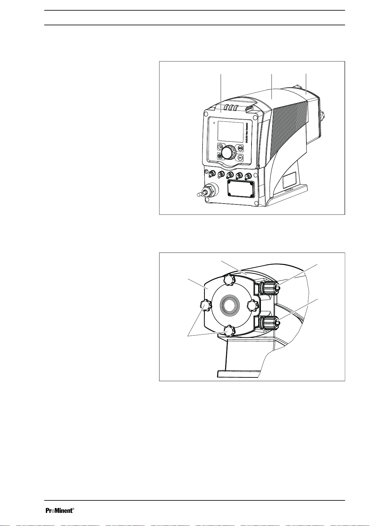
Overview of equipment
5.1
Fig. 2: Overview of equipment DFXa, complete
1 Control unit
2 Drive unit
3 Liquid end
Fig. 3: Liquid end DFXa
1 Dosing head
2 Pressure connector (delivery status)
3 Suction connector (delivery status)
4 Star screws
5 Bearing cover
15
Page 16
a)
b)
P_G_0105_SW
12 14
15
13
10
11
3
1
5
4
2
9
8
7
6
Overview of equipment and control elements
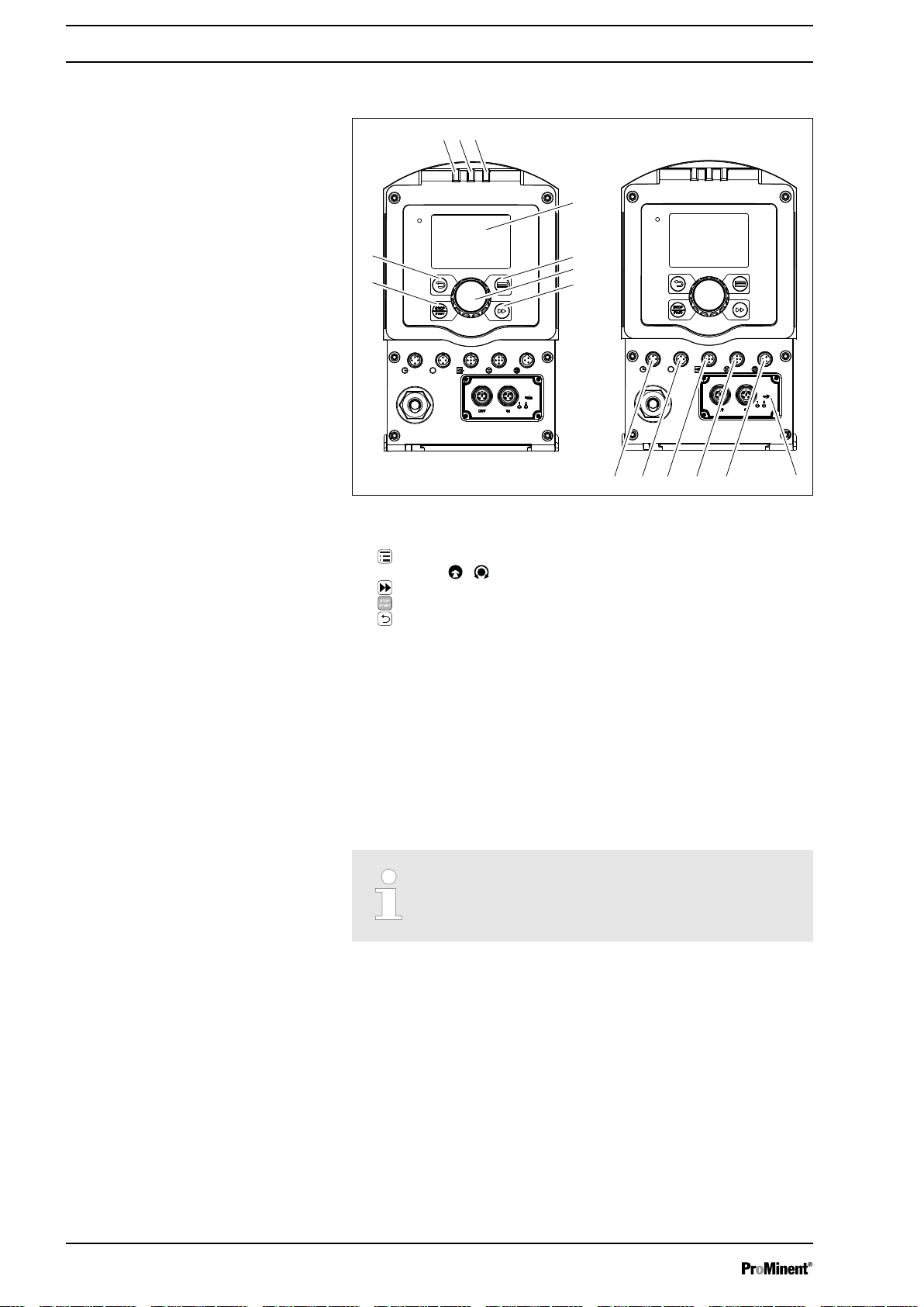
5.2 Control elements
Control elements, overview
Fig. 4
1 LCD screen
2
[Menu]
3
Clickwheel
4
5
6
key
[Priming]
key
[STOP/START]
[Back]
key
key
7 Fault indicator (red)
8 Warning indicator (yellow)
9 Operating indicator (green)
10 "Config I/O” terminal
11 "Hose rupture indicator" terminal
12 "External control" terminal
13 "Metering monitor" terminal (no function)
14 "Level switch" terminal
15 Slot for relays and optional modules
5.2.1 Control elements
Use this overview to familiarise yourself with the keys
and other control elements on the pump!
16
Page 17
10.0
10.0 mA
ANALOG
4..20mA
l/h
B1150
1
3
2
AUX
30.0
Level
MANUAL
l/h
Service: 600 h
MANUAL
Level error!
B1151
a)
b)
Level
602371
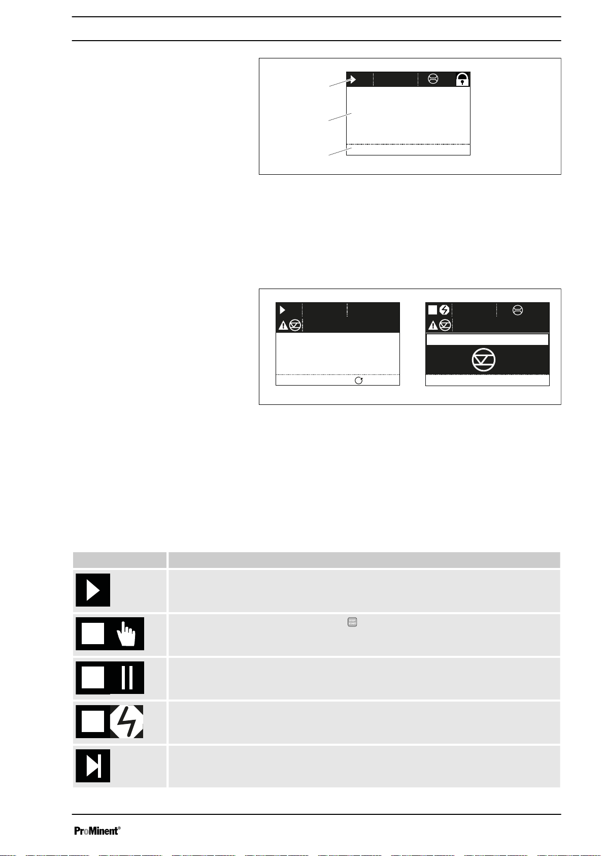
Identifier and fault displays on the LCD
screen
Overview of equipment and control elements
Fig. 5: Structure of continuous display
1 Status bar
2 Continuous display, central area
3 Secondary display
Refer to the chapter entitled "Main displays and secondary displays" in the
Appendix for the different main displays and secondary displays.
The LCD screen supports the operation and adjustment of the pump using
various information and identifiers:
Tab. 1: Identifiers and error displays:
Identifier Meaning
The pump is working or waiting for a starting signal.
The pump was manually stopped using the
The pump was remotely stopped (Pause) - via the "External" terminal.
The pump was stopped by an error.
Fig. 6: a) Continuous display with warning message; b) Continuous display
with fault message. Explanation of the symbols in the following tables.
The above Figure, Part a) shows that:
n the pump is in operation
n is in
n a
n the capacity of 30.0 l/h has been set
n the pump has performed 602371 revolutions to date
‘Manual’
‘level’
operating mode
warning message is pending
[STOP/START]
key.
Only with cyclical batch metering: the pump is waiting for the next cycle.
17
Page 18
Overview of equipment and control elements
Identifier Meaning
‘AUX’
‘memory’
Only with
The pump is currently pumping at auxiliary capacity.
Only in
the auxiliary function "Memory" has been set.
The pump is in
The
The pump is in
The
A hose rupture indicator is connected.
The pump is in the
‘Access protection’
‘CONTACT’
‘ANALOG’
‘Curve è linear’
‘ANALOG’
and
type of processing is set.
: the pump software is locked.
‘BATCH’
operating mode.
operating mode.
‘Curve è Upper side band’
‘Menu’
(Set up).
operating modes:
type of processing is set.
Further explanations can be found in the "Trouble‐
shooting" chapter.
The pump only shows the metering volume and the
capacity in the calibrated state in l or l/h or in gal or gal/h
(US gallons).
5.2.2 Key functions
Key Application In the continuous displays In the menu
[Back]
[STOP/
START]
Start pump Start pump
[Menu]
press - Go back to the previous menu
item (or a continuous display) without saving
press Stop pump, Stop pump,
press Go to the menu Go back to a continuous display
[Priming]
[Clickwheel]
[Clickwheel]
press Priming * Priming *
press Start batch (only in
mode),
Acknowledge errors
turn Switch between the continuous dis‐
plays
18
‘Batch’
operating
Go to next menu item (or a contin‐
uous display)
Confirm entry and save
Change figure or change selection
Page 19

Overview of equipment and control elements
* When priming the pump does not run at maximum
number of revolutions.
[Priming] is pressed in ‘Stop’ state, then [Priming]
If
has top priority as long as the button is pressed.
Refer to the "Set-up basics" chapter for how to adjust fig‐
ures
19
Page 20

Functional description
6 Functional description
Device
6.1
An electric motor drives a rotor. Rollers are fitted to the ends of the rotors,
which press the pump hose against the inner curvature of the dosing
head. The peristaltic pump operates by the rollers driving the feed chem‐
ical through the pump hose. The feed chemical is primed by the pump
hose automatically returning to its initial position.
6.2 Capacity
The capacity that has been set regulates the pump itself.
6.3 Operating modes
Operating modes are selected via the "Operating modes" menu.
"Manual" operating mode
"Contact" operating mode
"Batch" operating mode
"Analog" operating mode
Refer to the "Hierarchy of Operating Modes, Functions and Fault Statuses"
for the order of the various operating modes, functions and fault statuses.
‘Manual’
This operating mode provides the option of controlling the pump externally
by means of potential-free contacts (e.g. by means of a contact water
meter). “Pulse Control” can be used to preselect the metering volume in
the
This operating mode provides the option of working with large metering
volumes. Metering can be triggered either by pressing the
by a pulse received via the "External control" terminal via a contact or a
semiconductor switching element. It is possible to pre-select a metering
volume (batch) and a metering time using the
menu.
The capacity is controlled using an analogue current signal via the
"External control" terminal. Processing of the current signal can be prese‐
lected using the control unit.
operating mode permits you to operate the pump manually.
‘Settings’
menu.
[Clickwheel]
[Clickwheel]
in the
‘Settings’
or
6.4 Functions
Refer to the "Hierarchy of Operating Modes, Functions and Fault Statuses"
for the order of the various operating modes, functions and fault statuses.
The following functions can be selected using the
20
‘Settings’
menu:
Page 21

"Calibrate" function
Functional description
The pump can also be operated in a calibrated state in all operating
modes if it is to meter extremely precisely. This can be useful with highviscosity feed chemicals but less so with feed chemicals with a similar con‐
sistency to water.
"Auxiliary capacity” function
"Timer" function
"Level switch" function
"Pause" function
"Stop" function
"Priming" function
This facilitates the switch-over to a fixed adjustable capacity in the
via the "External control" terminal.
This permits a simple timer program to be set up without the need for an
additional timer module.
The following functions are available as standard:
Information about the liquid level in the dosing tank is reported to the
pump. A two-stage level switch has to be fitted for this purpose, which is
connected to the "Level switch" terminal. A suction lance with continuous
level measurement can also be connected to the pumps.
The pump can be remotely stopped via the "External control" terminal.
The pump can be stopped without disconnecting it from the mains/power
supply by pressing
Priming can be triggered by pressing
[STOP/START]
.
[ Priming]
.
‘menu’
6.5 Relay (options)
The pump has several connecting options available:
"Fault indicating relay" option
"Fault indicating and pacing relay" option
“mA-Output" option
6.6
LED displays
LED display Colour lit lights up flashes
The relay can close a connected power circuit (e.g. for an alarm horn) in
the event of warnings or fault messages (e.g.
The relay can be retrofitted through the slot in the front of the pump – refer
to the installation instructions for "Retrofitting relays".
This combined relay can generate a contact for an adjustable volume via
its pacing relay in addition to functioning as a fault indicating relay.
The relay can be retrofitted through the slot in the front of the pump.
The current output signal I indicates the pump's actual calculated metering
volume. The relay can be retrofitted through the slot in the front of the
pump.
The option also always includes a fault indicating relay or a pacing relay.
‘Warning level’
).
Fault indicator red A fault message is
Warning indicator yellow A warning message is
pending
pending
21
- undefined oper‐
ating status
- -
Page 22

Functional description
LED display Colour lit lights up flashes
Operating display green The pump is ready for
operation
During every revolution:
Capacity greater than 10
During every 1/2 revolu‐
Capacity less than 10 l /
During every 1/8 revolu‐
Capacity less than 1 l / h
Capacity less than 500
- -
l / h
tion:
h
tion:
every 4 s:
ml / h
6.7 Hierarchy of operating modes, functions and fault statuses
The different operating modes, functions and fault statuses have a dif‐
ferent impact on whether and how the pump reacts.
The following list shows the order:
1. - Priming
2. - Stop
3. - Error, Pause
4. - Auxiliary capacity
5. - Manual, Analog, Contact, Batch, Fieldbus
-
-
-
-
Comments:
re 1. - “Priming" can take place in any pump mode (providing it is
re 2. - "Stop" stops everything.
re 3. - "Error", and "Pause" stop everything apart from "Priming".
re 4. - "Auxiliary capacity" always has priority over the capacity specified
working).
by an operating mode listed under 5 or the fieldbus.
22
Page 23
7 Assembly
B1147
Assembly
User qualification: Technical personnel and service - see
of personnel’ on page 12
Refer to the correct dimensional drawings for the pump
from the online version of the operating instructions on
our website. www.prominent.com
Compare the dimensions on the dimensional drawing
with those of the pump.
CAUTION!
Danger from incorrectly operated or inadequately main‐
tained pumps
Danger can arise from a poorly accessible pump due to
incorrect operation and poor maintenance.
– Ensure that the pump is accessible at all times.
–
Adhere to the maintenance intervals.
Ä ‘Qualification
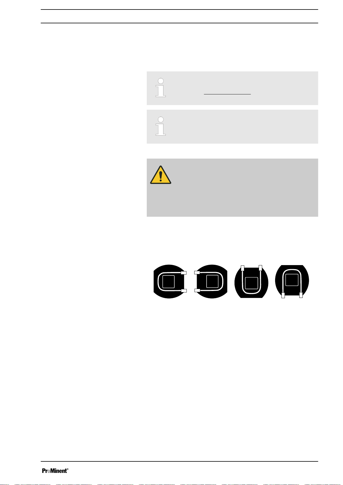
7.1 Changing dosing head alignment
The dosing head can be aligned in 4 directions:
Fig. 7: Alignment of dosing head: to the right, to the left, up, down
To change the dosing head alignment, proceed as follows:
23
Page 24
P_DX_0180_SW
1
2
3
4
5
6
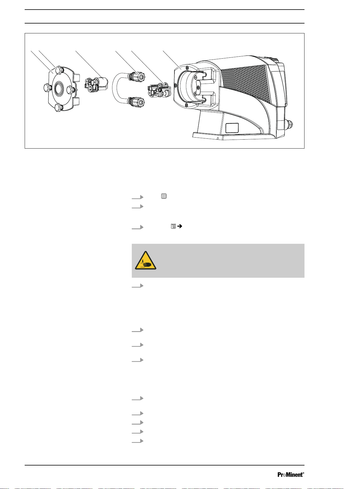
Assembly
Fig. 8
n Ensure that the system is at atmospheric pressure.
n Adhere to the material safety data sheet for the feed chemical.
n Prevent the escape of feed chemical.
n If necessary take protective measures.
1.
Press
[STOP/START]
to bring the pump to a stop (manually).
2. Empty the liquid end (turn the liquid end upside down and allow the
feed chemical to run out; flush out with a suitable medium; flush the
liquid end thoroughly when using hazardous feed chemicals!).
3.
Go to the
‘Go to change position?’
ð
‘Hose replacement’
appears.
menu.
WARNING!
The rotating rotor may crush things or draw them in.
– The bearing cover must not be removed yet.
‘Yes’
4. Confirm the question with
The rotor turns slowly and the following appears:
ð
‘ Please wait...’
.
The rotor stops and
.
‘Remove cover and take out the rotor!’
appears (the corresponding rotor half flashes in the animation).
5. Loosen 4 star screws (2) on dosing head (6) and remove with
bearing cover (1).
6. Pull rotor half (3) flashing in LCD screen out of dosing head (6) (if
required, use plastic tool to release it).
7. Press the Clickwheel.
The rotor turns slowly and the following appears:
ð
‘ Please wait...’
The rotor stops and
.
‘Please change the tube!’
appears.
8. Snap two hydraulic connectors out of dosing head (5) - away from
pump - and remove along with hose (4).
9. Also pull 2nd rotor half (5) out of dosing head (6).
10. Remove 4 Torx screws from rear of dosing head.
11. Align dosing head as desired (to left, to right, up, down).
12. Put 4 Torx screws back in and manually tighten.
24
Page 25
Assembly
13. Place 2nd rotor half (5) on drive axle in dosing head with "This side
DOWN" surface being located first - the rollers must point towards
the recesses for the hydraulic connectors.
14. Insert hose (4) in dosing head (5) and snap the two hydraulic con‐
nectors into place - round side in dosing head (5).
15. Press the Clickwheel.
The rotor turns slowly and the following appears:
ð
‘ Please wait!’
The rotor stops and
16. Re-insert 1st rotor half (3) - the surfaces of the two rotor halves
must be perfectly flush.
17. Press the Clickwheel.
The rotor turns and the following appears:
ð
‘Please wait...’
The rotor stops and
18. Place bearing cover (1) on dosing head (6).
19. Initially only loosely screw all 4 star screws (2) into dosing head (6).
20. Manually tighten the 4 star screws (2).
21. Press the Clickwheel.
‘Run in tube?’
ð
‘Yes’
/
22. Selecting
23.
You can return to the continuous display by pressing the
[No]
.
‘Insert rotor again!’
.
‘Install Cover again!’
appears.
‘No’
exits this macro.
appears.
appears.
key.
If the dosing direction is also to be reversed, this can be
done by going to ‘Settings
è
Dosing direction è ...’.
25
Page 26
Installation, hydraulic
8 Installation, hydraulic
Safety information
User qualification: Technical personnel and service - see
of personnel’ on page 12
CAUTION!
Warning of feed chemical spraying around
An unsuitable feed chemical can damage the parts of
the pump that come into contact with the chemical.
– Take into account the resistance of the wetted mate‐
rials and the ProMinent Resistance List when
selecting the feed chemical - see the ProMinent
Product Catalogue or visit ProMinent.
CAUTION!
Warning of feed chemical spraying around
An unsuitable feed chemical may cause premature wear
to the pump hose.
– Observe the pump hose's resistance and "Chemical
Resistance List DFXa" available at www.promi‐
nent.com when selecting the feed chemical.
CAUTION!
Warning of feed chemical spraying around
Pumps which are not fully installed hydraulically can
eject feed chemicals from the outlet openings of the dis‐
charge valves as soon as they are connected to the
mains.
– The pump must first be hydraulically installed and
then electrically.
In the event that you have failed to do so, press the
–
[STOP/START]
switch.
button or press the emergency-stop
Ä ‘Qualification
CAUTION!
Warning of feed chemical spraying around
Feed chemical can spray out of the hydraulic compo‐
nents if they are manipulated or opened due to pressure
in the liquid end and adjacent parts of the system.
– Disconnect the pump from the mains power supply
and ensure that it cannot be switched on again by
unauthorised persons.
Depressurise the system before commencing any
–
work on hydraulic parts.
CAUTION!
Danger of injury to personnel and material damage
The use of untested third party components can result in
injury to personnel and material damage.
– Only fit parts to metering pumps that have been
tested and recommended by ProMinent.
26
Page 27
P_DX_0179_SW
1 2 3 4 5
Installing hose lines
Installing suction and metering lines:
Installation, hydraulic
CAUTION!
Warning of feed chemical spraying around
The pipes can loosen or rupture if they are not installed
correctly.
– Route all hose lines so they are free from mechan‐
ical stresses and kinks.
Only use original hoses with the specified hose
–
dimensions and wall thicknesses.
– Only use clamp rings and hose nozzles that are
intended for the hose diameter in question to ensure
the long service life of the connections.
Align the lines so that the metering pump and the liquid
end can simply be removed if necessary.
1. First test which is the suction connector and which is the pressure
connector:
In
‘’ ‘Manual’
operating mode, briefly press
observe the rotor:
The rotor turns away from the suction connector and towards the
pressure connector.
If this arrangement is inappropriate, you can change it via the
dosing direction - go to
‘Settings è Dosing direction è ...’
2. Connect the suction line and discharge line as described below.
[STOP/START]
.
and
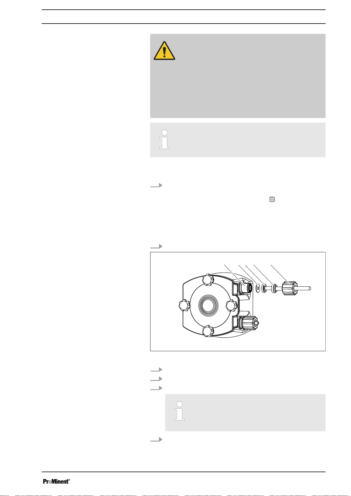
Fig. 9: Installing suction and metering lines
3. Shorten the end of the hose at right angles.
4. Unscrew union nut (2) and slide union nut over hose (3).
5. Push hose end over hose connector (4) as far as the stop.
Never re-use used PTFE seals.
An installation sealed in this way is not watertight.
This type of seal is permanently distorted when
subjected to pressure.
6. Tighten the union nuts.
27
Page 28

Installation, hydraulic
7. If you are only using a hose line and not a suction lance: Shorten
the free end of the suction line so that the end of the suction line
hangs just above the base of the feed chemical storage tank.
28
Page 29
9 Installation, electrical
Installation, electrical
User qualification: Electrical technician - see
on page 12
WARNING!
Danger of electric shock
A mains voltage may exist inside the device.
– Before any work, disconnect the device's mains
cable from the mains.
WARNING!
Risk of electric shock
This pump is supplied with a grounding conductor and a
grounding-type attachment plug.
– To reduce the risk of electric shock, ensure that it is
connected only to a proper grounding-type recep‐
tacle.
WARNING!
Risk of electric shock
In the event of an electrical accident, the pump must be
quickly disconnected from the mains.
– Install an emergency cut-off switch in the pump
power supply line or
Integrate the pump in the emergency cut-off man‐
–
agement of the system and inform personnel of the
isolating option.
Ä ‘Qualification of personnel’
WARNING!
Danger of electric shock
Incompletely installed electrical options can allow mois‐
ture into the inside of the housing.
– Fit appropriate modules into the slot on the front of
the pump or use the original blank cover to seal it in
a leak-tight manner.
WARNING!
Danger of electric shock
A mains voltage may exist inside the pump housing.
– If the pump housing has been damaged, you must
disconnect it from the mains immediately. It may
only be returned to service after an authorised
repair.
CAUTION!
Risk of short circuiting caused by moist pins
No moisture must reach the pins of the PROFIBUS
jack.
– A suitable PROFIBUS® plug or protective cap must
be screwed onto the PROFIBUS®
jack.
®
29
Page 30
Installation, electrical
CAUTION!
Material damage possible due to power surges
Should the pump be connected to the mains power
supply in parallel to inductive consumers (such as sole‐
noid valves, motors), inductive power surges can
damage the control when it is switched off.
– Provide the pump with its own contacts (Phase) and
supply with voltage via a contactor relay or relay.
Should this not be possible, then switch a varistor
–
(part no. 710912) or an RC gate (0.22 µF/220 Ω,
part no. 710802) in parallel.
CAUTION!
Bonding of the contacts of your switching relay
The high starting current can cause the contacts of the
on-site switching relay to bond together if the mains
voltage switches a solenoid metering pump on and off in
a process.
– Use the switching options offered by the external
socket to control the pump (functions: Pause, Auxil‐
iary frequency or Operating modes: Contact, Batch,
Analogue).
–
Use a starting current limiter if it is impossible to
avoid switching the pump on and off via a relay.
9.1
Supply voltage connector - mains voltage
Install the pump in line with best working practice and in accordance
with the operating instructions and applicable regulations.
WARNING!
Unexpected start-up is possible
The pump can start pumping and consequently feed
chemical may escape as soon as the pump is connected
to the mains/power supply.
– Avoid the escape of feed chemical.
–
If you have not done so, immediately press
[STOP/START]
mains voltage e.g. using an Emergency Stop switch.
– Refer to the material safety data sheet for your feed
chemical.
CAUTION!
If the pump is integrated into a system: Design the
system so that potential hazardous situations are
avoided by pumps starting up automatically subsequent
to unintended power interruptions.
or disconnect the pump from the
30
Page 31

9.2 Description of the terminals
4
32
1
B1079
B1080
9.2.1 "Config I/O” terminal
Installation, electrical
Simply disconnect the pump from the mains/power
supply for repair or maintenance work, among other
things.
–
With cables with plug: Provide adequate room
around the socket provided.
–
With cables without plug: Provide an appropriate,
easily accessible On/Off switching option in your
building installation.
Highlight the disconnection option as such and inform
staff about the electrical isolation option.
Connect the pump to the mains voltage using the mains cable.
There is an option to transmit the signals of 3 potential-free contacts as
inputs I: to the pump via the “Config I/O” terminal or issue contact signals
as Outputs O:.
Tab. 2: Assignment of pins
Pin Assignment 4-wire cable
Fig. 10: "Config I/O” terminal, pin assign‐
ment
Fig. 11: Plug to "Config I/O” terminal, pin
assignment
1 Config I/O 1 brown
2 Config I/O 2 white
3 Config I/O 3 blue
4 GND black
Configured as an input
Parameter Value
Voltage with open contacts 5 V
Input resistance 10 kΩ
Max. pulse frequency 50 pulses/s
Min. pulse duration 10 ms
31
Page 32

1
54
2
3
P_BE_0014_SW
Installation, electrical
Tab. 3: Control via:
Switching element Specification
potential-free contact Load: 0.5 mA at 5 V
Semiconductor switch Residual voltage < 2 V
Configured as an output
9.2.2 "External control" terminal
Parameter Value
Max. pulse frequency 50 pulses/s
Min. pulse duration 10 ms
Tab. 4
Switching element Specification
NPN output (Open Drain) 30 V max. voltage and 300 mA
max. current load per pin
CAUTION!
No protection provided for inductive loads.
– Provide a free-running diode when controlling a
delay.
The "external control" terminal is a 5-pole panel terminal. It is compatible
with 2- and 4-pin cables.
Only use a 5-pin cable with the "Auxiliary capacity" and "mA input" func‐
tions.
Electrical interface for pin 1 "Pause" - pin 2 "External contact" - pin 5 "Aux‐
iliary capacity"
Data Value Unit
Voltage with open contacts 5 V
Input resistance 10 kΩ
Max. pulse frequency 25 pulse/s
Min. pulse duration 20 ms
Control via:
Fig. 12: Assignment on pump
n potential-free contact (load: 0.5 mA at 5 V) or
n semiconductor switch (residual voltage < 0.7 V)
Electrical interface for pin 3 "mA input" (with identity code characteristic
"Control version": 2 and 3)
1
Data Value Unit
Input load, approx. 120 Ω
1
The metering pump starts running at approx. 0.4 mA (4.4 mA) and rea‐
ches maximum capacity at approx. 19.6 mA.
32
Page 33

2
45
1
3
P_BE_0015_SW
Fig. 13: Assignment on cable
Installation, electrical
Pin Function 5-wire cable 2-wire cable
1 Pause brown bridged at pin 4
2 External contact white brown
3 mA input* blue -
4 Earth GND black white
5 Auxiliary capacity grey -
*with identity code characteristic "Control version": 3
Refer to the functional description for the sequence of
functions and operating modes.
"Pause" function
"External contact" operating mode
"Analog" operating mode
The pump works if:
n pin 1 and pin 4 are connected to each other and the cable is con‐
nected.
n no cable is connected.
The pump does not work if:
n pin 1 and pin 4 are open and the cable is connected.
Acknowledge fault with ‘Pause’
Certain errors requiring acknowledgement can also be
acknowledged using ‘Pause’ instead of using the Quick‐
wheel.
The pump performs one or more revolutions if:
n Pin 2 and pin 4 are connected to each other for at least 20 ms. At the
same time, pin 1 and pin 4 must also be connected to each other.
The pump capacity and/or number of revolutions can be controlled by a
current signal. The current signal is connected between pin 3 and pin 4.
Pin 1 and pin 4 must also be connected.
“Auxiliary capacity” operating mode
The pump works at a pre-set capacity if:
n Pin 5 and pin 4 are connected to each other. At the same time, pin 1
and pin 4 must also be connected to each other. The auxiliary
capacity is factory-preset to maximum capacity.
9.2.3 "Level switch" terminal
There is an option for connecting a 2-stage level switch with pre-warning
and limit stop or a suction lance with continuous level measurement.
33
Page 34

3
21
P_BE_0016_SW
3
12
P_BE_0017_SW
3
21
P_BE_0016_SW
1
4
2
3
P_DE_0010_SW
Installation, electrical
9.2.3.1 Suction lance with 2-stage level switch
Electrical interface
Data Value Unit
Voltage with open contacts 5 V
Input resistance 10 kΩ
Control via:
n potential-free contact (load: 0.5 mA at 5 V) or
n semiconductor switch (residual voltage < 0.7 V)
Fig. 14: Assignment on pump
Pin Function 3-wire cable
1 Earth GND black
2 Minimum pre-warning blue
3 Minimum limit stop brown
Fig. 15: Assignment on cable
9.2.3.2 Suction lance with continuous level measurement
Electrical interface
Pin Designation Function
1 5 V supply
2 GND Reference potential
Fig. 16: Assignment on pump
3 Sensor TX TX communication interface (viewed
The cable between the suction lance and pump is an adapter cable
- with 5 pins at the suction lance end and 3 pins at the pump end.
Sensor + RX
5 V (4.85 V…5.25 V DC) feed to the
sensor and RX communication inter‐
face (viewed from sensor). Interrup‐
tion to the power supply for a commu‐
nication command max. 10 ms.
from sensor)
Fig. 17: Assignment on cable
9.2.4
9.2.5
"Metering monitor" terminal
This terminal has no function in the DFXa.
"Hose rupture indicator" terminal
There is an option to connect a hose rupture indicator.
Plug cable from hose rupture indicator into “Hose rupture indicator" ter‐
minal.
34
Page 35

Electrical interface
2
1
3
4
P_DE_0011_SW
2
1
3
4
P_DE_0012_SW
Specification Value
Installation, electrical
Supply voltage, approx.: +5 V, can be loaded to 20 mA (current
Power consumption: min. 10 mA, max. 20 mA (sensor pres‐
Sensor signal: potential-free contact (load: 0.5 mA at
Fig. 18: Assignment on pump
Pin Function 4-wire cable
1 Power supply (5 V) brown
2 not assigned white
3 Sensor signal blue
4 Earth GND black
limitation 150 mA)
ence detection)
+5 V) or
semiconductor switch (residual voltage
< 0.3 V)
Fig. 19: Assignment on cable
9.2.6 Relay
9.2.6.1
Tab. 5: DULCO flex Control DFXa
Identity code Designation Type Maximum voltage Maximum current
Relay functions
0 no relay - - -
1 Fault indicating relay Changeover contact 230 V AC 6 A
4 Fault indicating relay +
Pacing relay
C Fault indicating relay +
4-20 mA output
Releasing (N/C)
Energizing (NO)
Releasing (N/C) 24 V DC 100 mA
24 V DC
24 V DC
1 A
100 mA
Tab. 6: Relay type switches in the event of...
Relay type* Level
warning
Fault indicating relay: X X X
Warning relay: X - -
* Can be reprogrammed in the
9.2.6.2 "Fault indicating relay" output (identity code 1)
A fault indicating relay can be ordered as an option - refer to ordering
information in the appendix. It is used to emit a signal when there is a fault
with the pump and for the "Liquid level low, 1st stage" warning message
and "Liquid level low 2nd stage" fault message.
The fault indicating relay can be retrofitted and is operational once
attached to the relay board - refer to "Retrofitting relays" supplementary
operating instructions.
Level
low
‘Relay’
Processor
fault
menu.
35
Page 36

P_SI_0043
2
1
4
P_G_0072_SW
P_SI_0044
Installation, electrical
The behaviour is factory-programmed. If another switching function is
desired, the pump can be reprogrammed in the
‘Relay’
menu.
The relay can be retrofitted and is operational once it has been plugged
into the relay board.
Electrical interface
Data Value Unit
Maximum contact load at 230 V and 50/60
Hz:
Fig. 20: Assignment on cable
Minimum mechanical service life: 200,000 switching
Identity code 1
To pin VDE cable Contact CSA cable
1 white N/O (normally open) white
2 green N/C (normally closed) red
4 brown C (common) black
Fig. 21: Assignment on pump
9.2.6.3 Output for other relays (identity code 4)
A fault indicating and a pacing relay can be ordered as options - refer to
ordering information in the appendix. The pacing output is electrically iso‐
lated by means of an optocoupler with a semiconductor switch. The
second switch is a relay (also electrically isolated).
The behaviour is factory-programmed. If another switching function is
desired, the pump can be reprogrammed in the
The fault indicating/pacing relay can be retrofitted and is operational once
attached to the relay board - refer to the "Retrofitting relays" supplemen‐
tary instructions.
‘Relay’
8 A
operations
menu.
Fig. 22: Assignment on cable
Electrical interface
for fault indicating relay output:
Data Value Unit
Maximum contact load at 24 V and 50/60
2 A
Hz:
Minimum mechanical service life: 20,000,000 switching
operations
for semiconductor switch pacing relay:
Data Value Unit
Max. residual voltage at I
= 1 µA 0.4 V
off max
Maximum current 100 mA
Maximum voltage 24 VDC
Pacing pulse duration, approx. 100 ms
36
Page 37

Identity code 4
2
3
1
4
P_G_0073_SW
P_SI_0044
To pin VDE cable Contact Relay
1 yellow N/O (normally open) other relay
4 green C (common) other relay
3 white N/O (normally open) Pacing relay
2 brown C (common) Pacing relay
Fig. 23: Assignment on pump
9.2.6.4 "Current output plus relay" output (identity code C)
A relay combined with a current output can be ordered as an option. The
relay either switches as a fault indicating relay in the event of a fault on the
pump and with "Liquid level low 1st stage" warning messages and "Liquid
level low 2nd stage" fault messages or is used as a pacing relay.
The behaviour is factory-programmed. If another switching function is
desired, the pump can be reprogrammed in the
The variable to be signalled for the current output can be selected in the
‘ANALOG OUTPUT’
The current output plus relay can be retrofitted and operates once it is
plugged into the board.
menu.
Installation, electrical
‘Relay’
menu.
Fig. 24: Assignment on cable
Electrical interface
for current output
Data Value Unit
Open circuit voltage: 8 V
Current range: 4 ... 20 mA
Ripple, max.: 80 μA ss
Load, max.: 250 Ω
for semiconductor switch ("relay"):
Data Value Unit
Max. residual voltage at I
= 1 µA 0.4 V
off max
Maximum current 100 mA
Maximum voltage 24 VDC
Pacing pulse duration, approx. 100 ms
37
Page 38

2
3
1
4
P_G_0073_SW
Installation, electrical
Identity code c
To pin VDE cable Contact Relay
Fig. 25: Assignment on pump
1 yellow "+" Current
output
4 green "-" Current
output
3 white N/C (normally closed) or
Relay
N/O (normally open)
2 brown C (common) Relay
38
Page 39

10 Basic set-up principles
12.012.0
2315
7.0
CONTACT
bar
l/h
Settings
Service
Language
Makro operating mode
Information
Menu
German
English
...
〉Language
Language
German
Menu/Information
Path, derived:
...
〉Language
Language
English
German
Save
Menu/Information
Path, operating instructions:
Language
English
German
B0597
Please also refer to all the overviews covering
–
"Operating/set-up overview" and "Operating menu
for DULCO flex Control, complete" in the appendix
and the "Overview of equipment and control ele‐
ments" and "Control elements” chapters.
–
The pump exits the menu and returns to a contin‐
uous display if
pressed for 60 seconds.
10.1 Basic principles for setting up the control
Fig. 27 shows using the "Language" example how to set up something - in
turn:
n Sequence of displays
n The path derived from this
n The path as presented in the operating instructions
Fig. 26: Please read
Basic set-up principles
[Menu] is pressed or no key is
Fig. 27: "Setting up the language": As an example of set-up and path displays
Tab. 7: Legend:
Symbol Explanation
Press
Turn the
Press the
"Setting up the language" in detail
1.
To access the
The cursor immediately points to
ð
2. To switch from
3. To return to the
The cursor points to a language.
ð
4. To switch to
5. To save: press the
The software shows a display by way of confirmation.
ð
After 2 seconds, it returns to the higher-level
6.
To complete the setting: press
Alternatively: wait 60 seconds or exit the
key or using
‘Menu’
‘Information’
‘Language’
‘Deutsch’
[Clickwheel]
‘End’
.
[Menu]
[Clickwheel]
[Clickwheel]
: press the
to
menu: press the
: turn the
.
[Menu]
‘Information’
‘Language’
[Clickwheel]
[]
Menu.
‘Menu’
key.
.
: turn the
[Clickwheel]
.
‘Menu’
via the
[Clickwheel]
.
.
[Menu]
.
39
Page 40

B0777
5432
5
432
4
32
5
5432
2
543
a)
b)
c)
Basic set-up principles
Confirming an entry
Exiting a menu option without confirming it
Returning to a continuous display
Changing adjustable variables
Briefly press the
The software switches to the next menu point or back to the
ð
menu and saves the entry.
Press
The software switches to the next menu point or back to the
ð
menu without saving anything.
Press
The software cancels the entry and switches to a continuous
ð
display without saving anything.
[Back]
[Menu]
[Clickwheel]
.
.
.
Fig. 28: a) Changing from one figure to its initial figures; b) Changing the figure; c) Returning from the last figure to the
(complete) figure (to correct a wrong figure, for example).
Changing a (complete) number
Turn the
ð
Changing figures
1.
To adjust the value of a figure digit-by-digit, press
ð
2. To adjust the value of a figure, turn the
3.
To move to the next figure, press
point b).
4. To run through the figures again, if necessary (possibly because of
an incorrect figure), when you get to the last figure press
[Priming]
ð
[Clickwheel]
The value of the figure highlighted is raised or lowered.
The first figure is highlighted - see Figure above, point a)
.
[Priming]
[Clickwheel]
[Priming]
.
- see above Figure,
again - see above Figure, point c).
Now you can start from the beginning again.
.
40
Page 41

Confirming adjustable variables
10.2 Checking adjustable variables
Continuous displays
Before adjusting the pump, you can check the current settings of the
adjustable variables:
Basic set-up principles
Press the
ð
Simply turn the
display.
ð
[Clickwheel]
The software saves the entry.
Each time the
see a different continuous display.
1x.
[Clickwheel]
[Clickwheel]
if the pump is showing a continuous
engages when you turn it, you will
The number of continuous displays depends on the iden‐
tity code, the selected operating mode and the con‐
nected additional devices – see overview of "Continuous
displays" in the appendix.
Secondary displays
The lowest line of a continuous display shows different information (which
cannot be adjusted in the secondary display) - see "Continuous displays
and secondary displays" overview in the appendix.
You can access secondary displays via any continuous display as follows:
1. Press the
2. Providing there is a frame, you will see a different secondary display
10.3 Changing to Setting mode
In a continuous display, if you press
mode changes to
chapter entitled "Set up / Menu".
If under
[Clickwheel]
A frame appears around the secondary display.
ð
each time the
When you reach the secondary display you wish, leave the
[Clickwheel]
[Clickwheel]
and wait briefly.
‘Menu’
‘Access protect.’
lock symbol), then after pressing the
‘Password’
.
for 3 seconds.
engages when turned.
‘Menu’
. For more information refer to the following
only
‘Menu’
or
, the pump in Setting
‘All’
has been set up (top right
[Clickwheel]
, first enter the
41
Page 42

P_DX_0065_SW
Initial commissioning
11 Initial commissioning
User qualification: Technical personnel and service - see
Ä ‘Qualification
of personnel’ on page 12
WARNING!
The rotating rotor may catch and trap body parts.
– Only use the pump hose in the dosing head as out‐
lined in the instructions provided below.
The user should only now install the rotor half supplied - this will extend
the bearing service life of the pump hose.
Fig. 29: Starting state of rotor (bearing cover not shown)
1.
If still necessary: Press
stop (manually).
2.
Go to
‘Go to change position?’
ð
3. Confirm the question with
The rotor turns slowly and the following appears:
ð
‘Hose replacement’
WARNING!
The rotating rotor may catch and trap body parts.
– Only take off bearing cover once the pump prompts
you to do so.
Refit bearing cover once prompted to do so by the
–
operating instructions.
‘ Please wait...’
The rotor stops and
Rotor!’
appears.
‘Yes’
.
[STOP/START]
menu - used here to fit the hose.
appears.
.
to bring the pump to a
‘Please remove cover and take out the
42
Page 43

P_DX_0069_SW
P_DX_0068_SW
P_DX_0067_SW
Initial commissioning
4.
Loosen 4 star screws on dosing head and remove with bearing
cover.
5.
Insert the rotor half supplied.
6.
If the surfaces of the two rotor halves are perfectly flush, place
bearing cover on dosing head.
7. Initially only loosely screw all 4 star screws into dosing head.
8. Manually tighten the 4 star screws. The domed nut must again be
screwed onto the 4th star screw and tightened to provide a locking
function.
9. Press the Clickwheel.
The rotor turns slowly and the following appears:
ð
‘ Please wait...’
The rotor stops and
.
‘Please change the tube!’
appears. Please
ignore this.
43
Page 44

Initial commissioning
10. Press the Clickwheel
The rotor turns slowly and the following appears:
ð
‘ Please wait!’
The rotor stops and
this.
11. Press the Clickwheel.
The rotor turns and the following appears:
ð
‘Please wait...’
The rotor stops - this time standing on its tip - and
again!’
12. Press the Clickwheel.
‘Run in tube?’
ð
‘Yes’
/
13. Selecting
The pump draws in the pump hose (4) if
ð
14. The
In the first
extending or shortening the warning time for the next hose replace‐
ment. You can do this by changing the
‘No’
‘Run in tube...’
The rotor turns slowly a couple of times.
‘Tube change interval’
‘Revolutions’
‘Service è Hose’
15. To reset the warning time, press the
‘Reset interval now!’
ð
16. To complete the hose replacement, press the
‘Complete!’
ð
the pump still needs to be stopped manually. If necessary, now
restart the pump using the
.
‘Insert rotor again!’
.
appears. Please ignore this.
appears.
appears. Please ignore
‘No’
exits this macro.
‘Yes’
is selected.
appears.
menu appears.
menu item, you have the option of
‘Revolutions’
.
[Clickwheel]
appears.
.
[Clickwheel]
and a hand symbol appear. This is a reminder that
[STOP/START]
key.
‘Install Cover
- also refer to
again.
44
Page 45

Set up /
‘Menu’
12 Set up /
‘Menu’
User qualification: Technical personnel and service - see
of personnel’ on page 12
–
Refer to all overviews covering "Operating/set up
overview" and "Operating menu DULCO flex Con‐
trol, complete" in the appendix and in the chapters
"Overview of equipment” and “Control elements".
–
The pump exits the menu and returns to a contin‐
[Menu] is pressed or if no key is
The
‘Menu’
is sub-divided as follows:
1 -
‘Information’
2 -
‘Settings’
3 -
‘Hose replacement’
4 -
‘Timer’
5 -
‘Service’
6 -
‘Language’
uous display if
pressed for 60 seconds.
Ä ‘Qualification
12.1
12.2
‘Information’
‘Settings’
‘Menu / Information è ...’
The
‘Information’
parameters and counters. The number and type can depend on the pump
settings.
‘Menu / Information è Settings è ...’
The
‘Settings’
1 -
‘Operating mode’
2 -
‘Dosing direction’
3 -
‘Concentration’
4 -
‘Calibrate’
5 -
‘System’
6 -
‘Inputs/outputs’
7 -
‘Priming time’
8 -
‘Set time’
9 -
‘Date’
menu provides information on your pump and certain
menu generally includes these setting menus:
12.2.1
‘Operating mode’
‘Menu / Information è Settings è Operating mode è ...’
45
Page 46

Set up /
12.2.1.1
‘Menu’
‘Manual’
‘Menu / Information è Settings è Operating mode è Manual’
‘Manual’
The capacity can be set in the continuous displays of this operating mode.
operating mode allows you to operate the pump manually.
12.2.1.2
‘Contact’
‘Menu / Information è Settings è Operating mode è Contact
è
...’
The
‘Contact’
which you can preset.
You can trigger metering via a pulse sent via the "External control" ter‐
minal.
The purpose of this operating mode is to convert the incoming pulses into
a metering volume, which you can preset.
operating mode enables you to meter metering volumes,
CAUTION!
The pump maintains the capacity when changing over
from
‘Manual’
mode.
operating mode to
‘Contact’
operating
The maximum capacity can be set in ‘Contact’ operating
mode.
Memory - Pulses not yet processed
Contact water meter
12.2.1.3
‘Batch’
You can also activate the
fier). When
volume, which could not be processed, up to the maximum capacity of the
memory of 99,999 l. If this maximum capacity is exceeded, the pump goes
into fault mode.
Using "Pulse control" you can ideally adapt the pump to the relevant
process, for example in conjunction with contact water meters.
‘Memory’
CAUTION!
– Only with
[STOP/START]
(
‘Menu / Information è Service è Clear counters’
or the "Pause" function is activated, the
cleared.
‘Memory’
is activated, the pump adds up the remaining
‘Memory’
function extension ("memory" identi‐
-
‘off’
or empty the contact memory
: If you press
‘Memory’
)
is
‘Menu / Information è Settings è Operating mode è Batch è ...’
The
‘Batch’
umes or metering times.
You can trigger the metering volume using the
already switched to the
them via a pulse using the "External control" terminal.
operating mode enables you to pre-select large metering vol‐
‘Push’
[Clickwheel]
continuous display. You can also trigger
if you have
46
Page 47

Memory - remaining volume not yet pro‐
cessed
Set up /
You can also activate the
fier). When
volume, which could not be processed, up to the maximum capacity of the
memory of 99,999 l. If this maximum capacity is exceeded, the pump goes
into fault mode.
‘Memory’
CAUTION!
– The pump maintains the capacity when changing
over from
ating mode.
– When you press
function is activated, the
‘Memory’
is activated, the pump adds up the remaining
‘Manual’
function extension ("memory" identi‐
operating mode to
[STOP/START]
‘Memory’
‘Batch’
or the "Pause"
is cleared.
‘Menu’
oper‐
In operation, the batch size can be changed more easily
by using the "Batch size" continuous display.
12.2.1.4
‘Analog’
(option)
‘Menu / Information è Settings è Operating mode è Analog è ...’
The secondary display "Signal current" indicates the incoming current.
You can select 5 types of current signal processing:
n
‘0 - 20 mA’
n
‘4 - 20 mA’
n
‘Linear curve ’
n
‘Lower side band’
n
‘Upper side band’
‘0 - 20 mA’
At 0 mA the pump is stationary –
At 20 mA the pump works at maximum speed.
‘4 - 20 mA’
At 4 mA the pump is stationary –
At 20 mA the pump works at maximum speed.
With current signals of less than 3.8 mA, an error message appears and
the pump stops (e.g. if a cable has broken).
‘Linear curve’
The "Linear curve" symbol appears on the LCD screen. You can enter any
speed behaviour proportional to the current signal. For this purpose, enter
any two points P1 (I1, F1) and P2 (I2, F2) (F1 is the speed at which the
pump is to operate at current I1, F2 is the speed at which the pump is to
operate at current I2...); this defines a straight line and thus the behaviour
is specified:
47
Page 48

I [mA]
I 1
I 2
F1
F2
Fmax
0 20
P1
P2
B0088
I [mA]
I 1 I 2
F2
F1
0 20
a) b)
P1
P2
Fmax
B0089
I [mA]
I 1
I 2
F1
0 20
P1
P2
F2
Fmax
Set up /
‘Menu’
Fig. 30: Speed-current diagram for "Linear curve"
Plot a diagram similar to the one above – with values for
(I1, F1) and (I2, F2) – so that you can set the pump as
desired!
The smallest processable difference between I1 and I2
is 4 mA (ll I1-I2 ll ≥4 mA).
Error processing
Error processing
In the
‘Error message’
menu item, you can activate error processing for
these types of processing.
‘Lower side band’
Using this type of processing, you can control a metering pump using the
current signal as shown in the diagram below.
However, you can also control two metering pumps for different feed
chemicals via a current signal (e.g. one acid pump and one alkali pump
using the signal of a pH sensor). To do this, connect the pumps electrically
in series.
In the
‘Error message’
menu item, you can activate error processing for
these types of processing.
Fig. 31: Speed-current diagram for a) Lower side band, b) Upper side band
‘Upper side band’
48
Page 49

12.2.2 Dosing direction
12.2.3 Concentration
Set up /
Using this processing type, you can control a metering pump using the
current signal as shown in the diagram above.
Everything functions according to the
cessing.
‘Lower side band’
type of the pro‐
‘Menu’
‘Menu / Information è Settings è Dosing direction’
The
‘Dosing direction’
direction:
n clockwise
n anti-clockwise
menu enables you to select the pump’s dosing
‘Menu / Information è Settings è Concentration è ...’
The desired mass concentration of feed chemical that will subsequently be
required in the dissolving medium (e.g. the main flow) can be entered
directly in the "Concentration" continuous display.
The principle of entering the concentra‐
tion:
1. Select the operating mode.
2. Go to
3. Then set the data required for the feed chemical and dissolving
4. Set the desired concentration in the "Concentration" continuous dis‐
‘Set up’-‘Concentration’-‘Concentration control’
‘Active’
medium.
play.
.
–
The "Concentration" continuous display only
and set to
appears, if:
–
the pump is calibrated.
–
the ‘Concentration’ menu was run through in
the operating mode used.
–
and ‘Concentration control’ was switched to
‘active’ - in the operating mode being used.
–
The "Concentration" continuous display switches to
the "%" display mode at concentrations above
999.99 ppm.
–
When changing between operating modes, the
pump saves the settings for each operating mode provided it is connected to supply voltage.
–
If the pump is to display the concentration as a
volume concentration, enter "1.00" kg/l for the den‐
sity of the feed chemical.
12.2.3.1
‘Manual’
operating mode (settings for the
‘Menu / Information è Settings è Concentration
è
Concentration control è Flow of main medium è ...’
‘Concentration’
49
function)
Page 50

Set up /
‘Menu’
The "Concentration input" in
metering a substance into pipework containing a medium flowing at a con‐
stant rate (
tration in the flow.
‘main flow’
CAUTION!
Danger of concentrations being too high
The metering pump can continue to meter if the flow falls
or stops entirely.
– Take system-based precautions to prevent the
metering pump from continuing to meter in these cir‐
cumstances.
‘Manual’
) in such a way that it has a specific mass concen‐
operating mode is intended for
The prerequisites are that:
Procedure
n the flowing medium has the same density as water (1 kg/l
n the mass concentration of the feed chemical is known - see the feed
chemical safety data sheet (e.g. with 35% sulfuric acid: 35 %)
n the density of the feed chemical is known - see the feed chemical
safety data sheet (e.g. with 35% sulfuric acid: 1.26 kg/l ≜ g/cm3)
n The measurement unit for the liquid volume is set in the
è
Volume unit’
CAUTION!
The precision of the concentration is strongly dependent
on:
– the precision of the metering pump calibration.
–
1. Calibrate the metering pump if it is not yet calibrated - see chapter
‘Set up’-‘Calibration’
2. Select
in other operating modes remain saved).
3. Select
4. Set
‘active’
[Clickwheel]
5. Set the
[Clickwheel]
6. Set the
[Clickwheel]
7. Set the (mass)
The
ð
8.
Press
A continuous display appears.
ð
9. Turn the
play (ppm or %).
10. Enter the required mass concentration of feed chemical in the main
flow by pressing and turning the
menu.
the precision of the inputs.
chapter.
‘Manual’
‘Concentration’
‘Main medium flow’
-
‘Operating mode’
in the
in the
‘Concentration control’
.
.
(settings potentially configured
‘Set up’
(in the pipework) and then press the
menu.
‘Feed chemical mass concentration’
.
‘Feed chemical density’
‘Concentration’
[Menu]
.
[Clickwheel]
menu appears.
to go to the "Concentration" continuous dis‐
[Clickwheel]
menu item and press the
and press the
and press the
.
≜ g/cm3)
‘System
[Clickwheel]
.
Tab. 8: Possible values of adjustable variables
Adjustable variable Lower value Upper value Increment
Flow in m3/h
Mass concentration in % 000.01 100.00 000.01
Mass density in kg/l 0.50 2.00 0.01
0000.1 9999.9 0000.1
50
Page 51

12.2.3.2
‘Contact’
operating mode (settings for
è
Concentration control è Contact distance è ...’
‘Concentration’
function)
‘Menu / Information è Settings è Concentration
Set up /
‘Menu’
The prerequisites are that:
The "Concentration input" in
metering a substance into pipework containing a medium flowing at a vari‐
able rate in such a way that there is a specific mass concentration in the
flow.
CAUTION!
Danger of concentrations being too high
The metering pump can continue to meter if the flow falls
or stops entirely.
– Take system-based precautions to prevent the
metering pump from continuing to meter in these cir‐
cumstances.
n the flowing medium has the same density as water (1 kg/l
n the mass concentration of the feed chemical is known - see the feed
chemical safety data sheet (e.g. with 35% sulfuric acid: 35 %)
n the density of the feed chemical is known - see the feed chemical
safety data sheet (e.g. with 35% sulfuric acid: 1.26 kg/l ≜ g/cm3)
n a contact water meter is hydraulically installed and connected to the
external input of the metering pump.
n The measurement unit for the liquid volume is set in the
è
Volume unit’
menu.
‘CONTACT’
operating mode is intended for
≜ g/cm3)
‘System
Procedure
CAUTION!
The precision of the concentration is strongly dependent
on:
– the precision of the metering pump calibration.
–
the precision of the inputs.
1. Calibrate the metering pump if it is not yet calibrated - see chapter
‘Set up’-‘Calibration’
2. Select
3. Select
4. Set
5. Set the
6. Set the (mass)
7. Set the (mass)
8.
9. Turn the
10. You can enter the desired mass concentration using the
‘Contact’
ated menu items with the
ured in other operating modes remain saved).
‘Concentration’
‘active’
[Clickwheel]
in the
.
‘Contact distance’
[Clickwheel]
The
ð
Press
A continuous display appears.
ð
.
‘Concentration’
[Menu]
[Clickwheel]
play (ppm or %).
[Clickwheel]
.
chapter.
-
‘Operating mode’
[Clickwheel]
in the
‘Concentration control’
and press the
‘Feed chemical concentration’
‘Density dosing medium’
menu appears.
.
to go to the "Concentration" continuous dis‐
and simply confirm the associ‐
(settings potentially config‐
‘Set up’
menu.
menu item and press the
[Clickwheel]
and press the
and press the
.
[Clickwheel]
.
51
Page 52

Set up /
‘Menu’
Tab. 9: Possible values of adjustable variables
Adjustable variable Lower value Upper value Increment
Contact distance in l/contact 000.10 999.99 000.01
Mass concentration in % 000.01 100.00 000.01
Mass density in kg/l 0.50 2.00 0.01
‘Batch’
12.2.3.3
operating mode (settings for the
‘Concentration’
function)
‘Menu / Information è Settings è Concentration
è
Concentration control è Volume main medium è ...’
The prerequisites are that:
Procedure
The "Concentration input" in
metering a substance into the medium in a storage tank so that there is
then a defined mass concentration in the storage tank (when batching a
solution – do not forget to stir!).
n the medium in the storage tank has the same mass density as water
(1 kg/l ≜ g/cm3)
n the mass concentration of the feed chemical is known - see the feed
chemical safety data sheet (e.g. with 35% sulfuric acid: 35 %)
n the density of the feed chemical is known - see the feed chemical
safety data sheet (e.g. with 35% sulfuric acid: 1.26 kg/l
n The measurement unit for the liquid volume is set in the
è
Volume unit’
CAUTION!
The precision of the concentration is strongly dependent
on:
– the precision of the metering pump calibration.
–
1. Calibrate the metering pump if it is not yet calibrated - see
‘Calibration’
2. Select
ated menu items with the
ured in other operating modes remain saved).
3. Select
4. Set
‘active’
[Clickwheel]
5. Set the
and press the
6. Set the (mass)
[Clickwheel]
7. Set the (mass)
The
ð
8.
Press
A continuous display appears.
ð
9. Turn the
play (ppm or %).
10. You can enter the desired mass concentration using the
[Clickwheel]
menu.
the precision of the inputs.
chapter.
‘Batch’
-
‘Concentration’
in the
.
‘Volume main medium’
[Clickwheel]
.
‘Concentration’
[Menu]
[Clickwheel]
.
‘Batch’
operating mode is intended for
‘Operating mode’
[Clickwheel]
in the
‘Concentration control’
.
‘Feed chemical concentration’
‘Feed chemical density’
menu appears.
.
to go to the "Concentration" continuous dis‐
and simply confirm the associ‐
(settings potentially config‐
‘Set up’
menu.
menu item and press the
of the medium in the storage tank
and press the
and press the
≜ g/cm3)
‘System
‘Set up’
[Clickwheel]
-
.
52
Page 53

Tab. 10: Possible values of adjustable variables
Adjustable variable Lower value Upper value Increment
Volume in l 0000.1 9999.9 0000.1
Mass concentration in % 000.01 100.00 000.01
Mass density in kg/l 0.50 2.00 0.01
Set up /
‘Menu’
12.2.3.4
‘Analog’
operating mode (settings for the
‘Menu / Information è Settings è Concentration
è
Concentration control è Max.throughput main medium è ...’
The "Concentration input" in
metering a substance into pipework containing a medium flowing at a vari‐
able rate in such a way that there is a specific mass concentration in the
flow.
‘Concentration’
CAUTION!
Danger of concentrations being too high
The metering pump can continue to meter if the flow falls
or stops entirely.
– Take system-based precautions to prevent the
metering pump from continuing to meter in these cir‐
cumstances.
CAUTION!
Risk of incorrect concentrations
– After adjusting, check whether the concentrations at
various flows correspond to the desired result.
function)
‘Analog’
operating mode is intended for
The prerequisites are that:
Procedure
n the flowing medium has the same density as water (1 kg/l
n the mass concentration of the feed chemical is known - see the feed
chemical safety data sheet (e.g. with 35% sulfuric acid: 35 %)
n the density of the feed chemical is known - see the feed chemical
safety data sheet (e.g. with 35% sulfuric acid: 1.26 kg/l ≜ g/cm3)
n a flow meter with analogue output is hydraulically installed and con‐
nected to the external input of the metering pump.
n The measurement unit for the liquid volume is set in the
è
Volume unit’
1. Calibrate the metering pump if it is not yet calibrated - see chapter
‘Set up’-‘Calibration’
2. Check whether the metering pump is set to
metering mode.
3. Select
4. Set
‘0...20 mA’
press the
menu.
CAUTION!
The precision of the concentration is strongly dependent
on:
– the precision of the metering pump calibration.
the precision of the inputs.
–
chapter.
‘Automatic’
‘Analog’
operating mode and confirm with the
or
[Clickwheel]
‘4..20 mA’
.
in the
‘Select analog’
≜ g/cm3)
‘System
-
‘on’
[Clickwheel]
menu item and
.
53
Page 54

Set up /
‘Menu’
5. Select
6. Set
7. Set the
8. Set the (mass)
9. Set the (mass)
10.
11. Turn the
12. You can enter the desired mass concentration using the
‘Concentration’
‘active’
[Clickwheel]
in the
.
in the
‘Concentration control’
‘Max.throughput main medium’
the
[Clickwheel]
. (It is then assigned to the current value of 20 mA.)
‘Feed chemical concentration’
[Clickwheel]
.
‘Feed chemical density’
The
ð
Press
ð
play (ppm or %).
[Clickwheel]
‘Concentration’
[Menu]
A continuous display appears.
.
[Clickwheel]
.
CAUTION!
– Note the decimal point.
–
– The pump limits the upper value for the mass
to go to the "Concentration" continuous dis‐
The mass concentration is affected by
changes to the capacity.
concentration, because otherwise the incre‐
mental jumps when adjusting would be unac‐
ceptably large.
‘Set up’
menu appears.
menu.
menu item and press the
(in the pipework) and press
and press the
and press the
[Clickwheel]
.
The least significant figures of the value in the
continuous display cannot be changed at will
using the [Arrow keys], rather only in incremental
jumps resulting from the input data.
If necessary, change the capacity and adjust the
concentration; as you do this, the pump compen‐
sates via the speed.
Tab. 11: Possible values of adjustable variables
Adjustable variable Lower value Upper value Increment
Max. flow in m3/h
Mass concentration in % 000.01 100.00 000.01
Mass density in kg/l 0.50 2.00 0.01
0000.1 9999.9 0000.1
12.2.4 Calibrate
‘Menu / Information è Settings è Calibration è ...’
Accuracy of calibration
Normally the pump does not have to be calibrated.
However, the pump can be calibrated if viscous feed
chemicals are used or extremely high accuracy is
required.
54
Page 55

There are 2 options for calibrating the pump:
t
1
t
2
Q
1
Q
2
P_G_0071_SW
n Calibrate using
n
‘Calibrate’
12.2.4.1 Calibrate using calibr. factor
If you already know what calibration factor is needed for the pump to ach‐
ieve the desired accuracy, go to
appropriate calibration factor as a %.
12.2.4.2 Calibrate using a calibration procedure
If you don't know which calibration factor you need, use this calibration
procedure.
Set up /
‘Calibr. factor’
using a calibration procedure
‘Calibrate’-‘Calibr. factor’
WARNING!
If the feed chemical is hazardous, take appropriate
safety precautions when performing the following cali‐
bration instructions. Observe the material safety data
sheet for the feed chemical!
and enter the
‘Menu’
Preparation
Calibration procedure
1. Use the
[Clickwheel]
to scroll through the continuous displays to
check whether litres or gallons have been selected.
2. If the incorrect volume unit has been selected, correct it in the
‘Menu / Information è Settings è System è Volume unit’
menu.
3. Check whether the capacity in the continuous display is not too low
for calibration.
4. Lead the suction hose into a measuring cylinder containing the feed
chemical – make sure that the discharge hose is installed perma‐
nently (operating pressure, ...!).
5.
Prime the feed chemical (press
[Priming]
) if the suction hose is
empty.
1. Record the level in the measuring cylinder.
2.
Select the
press the
ð
3. To start calibration, press the
ð
‘Menu / Information è Settings è Calibrate’ ‘’
[Clickwheel]
The
‘Start calibration’
.
(PUSH) menu item appears.
[Clickwheel]
The
‘Calibrate ...’
menu item appears, the pump starts to pump
menu and
.
and indicates the number of revolutions.
55
Page 56

B1147
Set up /
‘Menu’
12.2.5 System
4. After a reasonable number of revolutions (a minimum of 200), use
the
[Clickwheel]
The
ð
the calibration volume.
5. Determine the required metering volume (difference between initial
volume - remaining volume in the measuring cylinder).
6. Use the
menu item and close.
ð
7. Press the
ð
[Clickwheel]
The pump switches to the
pump is calibrated.
The pump returns to the
to stop the pump.
‘Calibrate ended’
to enter this volume in the
[Clickwheel]
.
menu item appears. It asks you to enter
‘Calibrate ended’
‘Calibration result’
‘Menu / Information è Settings’
menu item - the
menu.
‘Menu / Information è Settings è System è ...’
The
‘System’
2 -
‘Configure dosing head’
3 -
‘Volume unit’
4 -
‘Start behaviour’
menu is split into the following sub-menus:
12.2.5.1
‘Configure dosing head’
‘Menu / Information è Settings è System
è
Configure dosing head è ...’
In the
‘Configure dosing head’
position for if you have turned it
because you can turn the dosing head as follows:
CAUTION!
Whenever the dosing head’s alignment has been
changed, the new alignment must be correctly stated
otherwise the
erly.
menu, you have to set the dosing head's
‘Tube Service’
will no longer work prop‐
12.2.5.2 Volume unit
‘Menu / Information è Settings è System è Volume unit è ...’
You can select another unit for the volume in the
56
‘Volume unit’
sub-menu.
Page 57

12.2.5.3 Start behaviour
Set up /
‘Menu’
‘Menu / Information è Settings è System è Start behaviour è ...’
You can specify the start behaviour of the pump once the supply voltage
has been switched on in the
Start behaviour Description
‘Behaviour on start’
sub-menu.
12.2.6 Inputs/outputs
‘always STOP’
‘always on’
‘last status’
The pump always wakes up in “Manual stop via
[STOP/START]
the
It can only be started by pressing
[STOP/START]
The pump always starts immediately.
The pump always adopts the last status it had
before the supply voltage was switched off.
.
‘Menu / Information è Settings è Inputs/outputs è ...’
The
‘Inputs/outputs’
1 -
‘Auxiliary capacity’
2 -
‘Relay1’
3 -
‘Relay2’
4 -
‘mA-Output’
7 -
‘Pause input’
6 -
‘Level monitoring’
menu is split into the following sub-menus:
(option)
(option)
(option)
(option)
key" mode.
12.2.6.1
12.2.6.2
‘Auxiliary capacity’
‘Relay1 (option)’
‘Menu / Information è Settings è Inputs/outputs
è
Auxiliary capacity è ...’
The programmable
switched over to an additional capacity that can be fixed in the
capacity’
It can be activated via the "External control" terminal. If
is being used, then the "AUX” identifier appears on the LCD screen.
Refer to the "Hierarchy of Operating Modes, Functions and Fault Statuses"
for the order of the various operating modes, functions and fault statuses.
menu.
‘Auxiliary capacity’
function enables the pump to be
‘Auxiliary
‘Auxiliary capacity’
‘Menu / Information è Settings è Inputs/outputs è Relay1 è ...’
The setting options for the ‘Relay’ function only exist if a
relay is fitted.
57
Page 58

Set up /
DULCO flex Control, DFXa
‘Menu’
Tab. 12: Relay, physical and pre-set to ...
Identity code specification Relay, physical Pre-set to ...
1 1 x changeover contact 230 V – 8 A Fault indicating relay, N/C
4 2 x N/O 24 V – 100 mA Fault indicating relay, N/C, and pacing
C 1 x N/O 24 V – 100 mA, + 4...20 mA
Relay type
Menu setting Effect
Timer The relay is available for the timer.
Fault The relay switches in the event of a fault message (red LED*).
Warning The relay switches in the event of a warning message (yellow LED*).
Warning + error The relay switches in the event of a warning message (yellow LED*) or a fault
Warning + error + stop The relay switches in the event of a warning message (yellow LED*) or a fault
Pump active The relay switches as soon as the pump is in standby and not in a state like
Speed The relay switches with every revolutions.
Metering / Batch The relay changes its state as soon as a metering volume / batch is being pro‐
output
You can reprogram the relays to these types:
message (red LED*).
message (red LED*) or a stop.
‘Pause’
cessed.
.
relay
Fault indicating relay, N/C
Relay polarity
12.2.6.3
12.2.6.4
‘Relay2 (option)’
‘mA-Output (option)’
* see the "Troubleshooting" chapter
You can set here how a relay is to switch.
Menu setting Effect
normally-closed (NC) The relay is closed in normal mode and opens
normally-open (NO) The relay is open in normal mode and opens
with a triggering event.
with a triggering event.
‘Menu / Information è Settings è Inputs/outputs è Relay2 è ...’
For more information on
on page 57
.
‘Relay2’
- see
Ä Chapter 12.2.6 ‘Inputs/outputs’
‘Menu / Information è Settings è Inputs/outputs è mA-Output
è
...’
58
Page 59

Set up /
You can set which current range is to be used at the mA output here.
You can then set whether, for example, the current capacity (litres / hour)
is to be signalled at the mA output and set the desired value for 20 mA.
You can also set the state which the mA output is to signal at 23 mA:
n Passive
n Fault
n Warning
n Warning + error
n Warning + error + stop
‘Menu’
12.2.6.5
12.2.6.6
12.2.7
‘Pause input’
‘Level monitoring’
‘Priming time’
‘Settings è Inputs/outputs è Pause è ...’
In the
‘Pause’
‘Pause’
tact signal.
menu, you can select whether the pump switches to
with a
‘normally-open’
(NO) or
‘normally-closed’
(NC) input con‐
‘Settings è Inputs/outputs è Level monitoring è ...’
In the
‘Level monitoring’
with standard 2-stage level monitoring or a continuous form.
menu, you can select whether the pump is to run
‘Menu / Information è Settings è Priming time è ...’
In the
‘Priming time’
to prime once
menu, you can select how long the metering pump is
[Priming]
has been pressed.
12.2.8
‘Set time’
‘Menu / Information è Settings è Set time è ...’
You can set the time in the
1. Use the dial to adjust a figure.
2.
Under
over to
You can also state when the pump is to change to and from
‘Summertime’
Check under
‘hemisphere’
Use
[Priming]
‘Auto. Summertime’
‘Summertime’
.
‘Location’
of the world.
59
‘Set time’
to move to the next figure.
you can select whether you wish to change
.
whether the pump is also set to your
menu.
Page 60

Set up /
12.2.9
‘Menu’
‘Date’
‘Menu / Information è Settings è Date è ...’
12.3
‘Hose replacement’
12.4 Timer
You can set the date in the
‘Menu / Information è Service è Hose replacement è ...’
This menu only appears once a manual stop has been performed using
[STOP/START]
Here you can replace a hose following the guidance provided. For the
detailed description - see
on page 86
‘Menu / Information è Timer è ...’
.
–
Please first read this chapter to get an overview.
You will then understand the timer better when
working through the chapter.
‘Date’
menu.
Ä Chapter 15.1 ‘Replacing pump hose’
12.4.1 Activation / deactivation
The timer DULCO flex Control can do the following at predefined times
and intervals or event-dependent:
n open / close the relays
n switch the level of a Config I/O output
n be triggered by the level at a Config I/O input
n start a delayer
n switch operating mode
n allow the pump to work at a defined capacity
n stop / start the pump
n trigger a batch (
‘Menu / Information è Timer è Activation è ...’
You can only program the timer when ‘Activation’ is set
to ‘inactive’ .
To program the timer, set
The first line of the timer menu
ð
‘Inactive’
‘Batch (time)’
.
)
‘Activation’
to
‘inactive’
‘Timer status’
.
then shows
To activate the timer, set
The first line of the timer menu
ð
‘active’
.
The timer starts working - the timer identifier
continuous display.
60
‘Activation’
to
‘Timer status’
‘active’
.
then displays
is visible in the
Page 61

12.4.2 Setting the timer
Set up /
‘Menu’
When ‘Activation’ is set to ‘active’ , the timer software
generates the state of the pump which the pump would
have precisely had at this time if it had been set to
‘active’ without any interruption.
Delayed, linked actions are unaffected by this.
‘Menu / Information è Timer è Set timer è ...’
You can create commands (also known as “program lines”) for a timer pro‐
gram in the
You can create up to 99 commands (program lines).
Create the command as follows:
1 - Create a
2 - Select the
3 - Select
4 - Check the command
5 - Create the next command – if necessary
‘Set timer’
necessary
‘Action’
menu.
‘new’
command (program line)
‘Triggering event’
and a value, if necessary
(trigger) and the time and/or interval if
The following administration functions are available to manage the com‐
mands (program lines):
1 - Reprogram program line (
2 - Check program line (
3 - Change program line (
4 - Delete individual program line (
(5 - Delete the entire program (
CAUTION!
The pump does not perform any plausibility check.
Please ensure before using that the timer actually does
what you expect of it. Please consider the consequences
for your system.
CAUTION!
If you wish to use automatic summer time adjustment
‘Settings’
(
02:00 a.m. and 03:00 a.m.
-
‘New’
)
‘Show’
)
‘Change’
‘Time’
)
‘Delete’
‘Clear all’
) avoid any triggering events between
)
one level higher))
Restriction with day numbers
If you wish to start an action of a certain day of each
month, note that the timer only permits days 01 - 28.
61
Page 62

12:00
Manual
20.00 l/h
workdays 1 (Mo-Fr)
Instruction 03/05
B1106
Set up /
‘Menu’
Using Config I/Os
If you wish to use Config I/Os as inputs or outputs, you
first need to configure them as a ‘Timer input’ or ‘Timer
output’ under ‘Menu / Information
è
Config I/Os è ...’.
è
Settings
12.4.2.1 Reprogram program line (
‘new’
)
12.4.2.1.1 Principle design of a program line
In principle, an (imaginary) program line / instruction is set up as follows:
Time event (trigger) Action
workdays 1
(Mo-Fr)
This corresponds to the following instruction:
WHEN triggering event, THEN action
The time event (trigger) defines what action or at what time an action is to
take place.
The action defines which type of action is to take place.
The finished program line/ instruction looks like this:
CAUTION!
‘Timer status’
If the
is set to
ther be set nor programmed!
To do so, set the
‘inactive’
.
Time of day
‘Timer status’
Manual 20.00 l/h
12:00
‘active’
, the pump can nei‐
under
‘Activation’
to
Example
Time event (trigger) Action
workdays 1 (Mo-Fr) Time of day 12:00 Manual 20.00 l/h
The example means:
When it is 12:00 on a workday, then the pump is to work in
mode at 20.00 l/h.
62
‘Manual’
Page 63

Tab. 13: Time events (triggers)
Time events (triggers) Description Remark
Set up /
‘Menu’
Time Switching time reached
For more information - see
12.4.2.1.3 ‘Selecting time events and
switching point’ on page 64
‘Init’
Thus declared is started at the begin‐
ning of the program process
Defined starting conditions - see
Ä Chapter 12.4.2.1.2 ‘ ‘Init’ Initial con‐
ditions’ on page 64
‘Delayer’
‘ Config I/O’
input 0/1 contact at input I: x Connector pins on the very left of the
Delay time of delayer D: xx expired -
*refer to “Overview of equipment” chapter
The
‘ Config I/O’
inputs first need to be assigned to the timer under
pump *
‘Menu / Information è Settings è Config I/Os è ...’
You can select an action and also a value:
Tab. 14: Action
Action Description Value
‘Manual’
‘Stop’
‘Relay 1 **’
Switch over in this operating mode Litre/h (
Stop pump --
Have the relay switch to status ... open
closed
.
‘Capacity’
Ä Chapter
)
‘Relay 2 **’
‘Contact’
‘Batch (input)’
‘Analogue’
‘ Start delayer’
‘Config I/O 1’
‘Config I/O 2’
‘Config I/O 3’
Have the relay switch to status ... open
Switch over in this operating mode --
Switch over in this operating mode --
Switch over in this operating mode --
Activate a delayer
Switch the level of the Config I/O 1
output to ...
Switch the level of the Config I/O 2
output to ...
Switch the level of the Config I/O 3
output to ...
* refer to the “Overview of equipment" chapter and
è
Settings è Config I/Os è ...’
** Option; needs to be assigned to the
è
Inputs/Outputs è Relay è Relay type’
operating instructions under
Tab. 15: Selected value ranges
Description Value range
closed
open
closed
open
closed
open
closed
‘Settings’
‘Menu / Information
‘Timer’
(under
- refer to this chapter of the
)
‘Settings
Line numbers 01 ... 99
Day (date) 01 ... 28
Time of day (hours) 00 ... 23
63
Page 64

Set up /
Description Value range
seconds 0001 ... 9999
No. of delayer D: 01 ... 15
‘Menu’
12.4.2.1.2
Example
triggering event (trigger) Action
Init - Relay 2 closed
Init - Contact -
12.4.2.1.3 Selecting time events and switching point
‘Init’
Initial conditions
Using the triggering event
ning of a program sequence.
The example means:
As soon as the programme is started (via
or mains voltage on),
mode’
to
‘Contact’
The cyclic time events periodically trigger actions. That is why a program
line consists of a cycle and a switching point.
The cycle specifies after which time the action is to be repeated.
The switching time specifies when the action is to take place.
‘Init’
initial conditions can be set at the begin‐
‘Timer è Activation è active’
‘Init’
sets
.
‘Relay 2’
to
‘closed’
and the
‘Operating
Example
Time events (triggers) Action
Cycle Switching time
workdays 1 (Mo-Fr) Time of day 12:00 Manual
Tab. 16: Cyclic time events
Cycle Time
‘hourly’
‘daily’
‘workdays 1 (Mo-Fr)’
‘workdays 2 (Mo-Sa)’
‘Weekend (Sa+Su)’
‘weekly’
‘monthly’
* Value range is restricted to 01 to 28 days.
hourly at mm Minute
daily at the time mm.ss, Monday to Sunday
daily at the time mm.ss, Monday to Friday
daily at the time mm.ss, Monday to Saturday
daily at the time mm.ss, Saturday and Sunday
weekly at the time mm.ss on day xxxxxx.
monthly at the time mm.ss on the day dd. Day* of the
month
64
Page 65

12.4.2.1.4 Delayer
Example of a program
Set up /
CAUTION!
If you wish to use automatic summer time adjustment
‘Settings’
(
between 02:00 and 03:00.
A time event lets you trigger an action precisely to the
minute.
If the action is to be triggered precisely to the second,
then you need to set up your programming on a delayer.
A delayer allows you to delay an action with regard to a time event
(trigger).
Delayers can be both time events and also actions.
-
‘Time’
) avoid in principle any time events
‘Menu’
No. Time event (trigger) Action
01 Config I/O 1 close Start Delayer 1 -
02 Config I/O 1 close Start Delayer 2 -
03 Config I/O 1 close Start Delayer 3 -
04 Init - Stop -
05 Delayer 1 after 60 sec Config I/O 2 close
06 Delayer 2 after 120 sec Manual 10 l/h
07 Delayer 3 after 180 sec Stop -
08 Delayer 3 after 180 sec Config I/O 2 open
The example means:
A flank at
n after 60 s output
n after a further 60 s, the pump pumps in
n stops after a further 60 s and output
A program line with a time event
ment
The
to be delayed (1 s 9,999 s = approx. 2 h 45 min).
The delayer itself must first have been called up by a time event as an
action. You can use 15 different delayers.
‘Config I/O 1’
10 l/h,
‘Delay time’
‘Delay time’
means that ...: :
‘Config I/O 2’
.
specifies by which time the start of the selected action is
is closed,
‘Delayer’
‘Manual’
‘Config I/O 2’
X thus also includes the ele‐
operating mode at
opens again.
–
With the time event ‘Delayer’ X, you can trigger an
action precisely to the second.
–
The clock of the DULCO flex Control has an accu‐
racy of ±1 s/24 h.
65
Page 66

Set up /
12.4.2.1.5 Inputs
Example
Time events (triggers) Action
Config I/O 1 Relay 2 open
12.4.2.1.6 Outputs
‘Menu’
A 0/1 contact signal, for example at pin 1 of the
be a triggering event.
The example means:
If an 0/1 contact signal is closed between Pin 1 of the
nector and Pin 4, then the
The timer can output a 1/0 contact signal e.g. between pin 3 of the
I/O’
connector and pin 4.
‘Relay 2’
should switch to
‘Config I/O’
‘Config I/O’
‘open’
terminal can
con‐
status.
‘Config
Example
Time events (triggers) Action
Cycle Switching time
workdays 1 (Mo-Fr) Time of day 12:00 Config I/O 3
The example means:
At 12:00 on workdays, the timer outputs a 1/0 contact signal e.g.
between pin 3 of the
12.4.2.2 1 time event - several actions
You can assign 1 time event to several actions. To do so, always use the
same cycle and the same switching time! :
Example
No. Time event (trigger) Action
01 workdays 1 (Mo-Fr) Time of day
12:00
02 workdays 1 (Mo-Fr) Time of day
12:00
‘Config I/O’
Stop -
Batch (input) 500 ml
connector and pin 4
03 workdays 1 (Mo-Fr) Time of day
12:00
04 - - ... .
Relay 1 -closed
–
For details on the sorting sequence of the program
lines see Ä ‘Sorting sequence’ on page 67.
–
The timer program can have a maximum of 99 pro‐
gram lines.
66
Page 67

12.4.2.3 Check program lines (
10:48
Manual
0.25 l/h
monthly
Command 01/05
B0781
on 21st
‘Show’
)
‘Menu / Information è Timer è Set timer è Show’
‘Show’
lets you check individual program lines / instructions.
1. Press the
This display appears:
ð
[Clickwheel]
on a program line / instruction.
Above the line Time event (trigger) and possible value
Below the line Action and value, if required
2. Turn the
Scroll from instruction to instruction.
ð
[Clickwheel]
.
The number of the program line or instruction (and the number
of the last program line or instruction) appears at the top in the
dark bar.
3. Pressing the
[Clickwheel]
returns you to
‘Set timer’
Set up /
.
‘Menu’
Sorting sequence
12.4.2.4 Change program lines (
As the timer software automatically sorts the program
lines, the numbers of the program lines can change if
you change something.
The timer software automatically sorts every newly programmed program
line / instruction after completing it (press the
[Clickwheel]
program lines.
The 1st sorting criterion is the type of time event (trigger) (for the
sequence refer to
mation on page 64
Ä Further information on page 63
).
and
Time-dependent program lines are ordered below each other initially after
the Switching point (2nd sorting criterion)
then after the length of the Cycle (3rd sorting criterion).
The 4th sorting criterion is the type of action (see also the programming
examples at the end of these instructions).
A purely time-controlled timer program will also run in this sequence.
‘Change’
)
‘Menu / Information è Timer è Set timer è Change’
1. Use the
[Clickwheel]
according to its number and press the
to select the required program line / instruction
[Clickwheel]
2. Click through the instruction and change it.
The timer software sorts a changed program line / instruction
ð
after completion with the
[Clickwheel]
possibly differently in
between the other program lines (Rules - see
sequence’ on page 67
).
67
) below the other
Ä Further infor‐
.
Ä ‘Sorting
Page 68

Set up /
12.4.2.5 Delete individual program lines (
‘Menu’
12.4.3 Clear all
‘Delete’
)
‘Menu / Information è Timer è Set timer è Delete’
1. Use the
according to its number.
2. The program line will be deleted as soon as you press the
[Clickwheel]
ð
[Clickwheel]
.
The timer software re-sorts the remaining programme lines
(Rules - see
to select the required program line / instruction
Ä ‘Sorting sequence’ on page 67
).
Delete all program lines
The option to delete all program lines is to be found one
level higher in the menu:
‘Menu / Information è Timer è Clear all’
‘Menu / Information è Timer è Clear all è ...’
Use the
‘Clear all’
menu to clear all instructions (the entire program).
12.4.4 Examples
Requirements:
n You have already worked with the pump type
n The time has been set (possible set under
è
Time’
Only possible with
‘Timer status’-‘Inactive’
‘Settings è Set time
).
68
Page 69

Set up /
‘Menu’
Example of "Weekday metering"
Task:
The pump is to meter 2 litres every half hour every weekday (Mon-Fri)
between 8:00 and 11:00:
Solution:
As you define switching times with the timer, you need to first define the
switching points at 08:30, 09:30 and 10:30.
To meter 2 litres, the pump needs to work in
for 10 min at a
thereby added to the switching points.
You also need to define the switching times to stop the pump at 08:40,
09:40 and 10:40 - paired with the
‘Capacity’
of 12,000 l/h. A
‘Halt’
‘Manual’ ‘operating mode’
‘Capacity’
action.
of 12,000 l/h is
Tab. 17: Program as program lines / instructions
No. Time event Action Comment
Switching time Capacity
01 workdays 1 (Mo-
Fr)
02 workdays 1 (Mo-
Fr)
03 workdays 1 (Mo-
Fr)
08:30 Manual 12,000 l/h Meter at 12,000
l/h
08:40 Stop - Stop
09:30 Manual 12,000 l/h Meter at 12,000
l/h
04 workdays 1 (Mo-
Fr)
05 workdays 1 (Mo-
Fr)
06 workdays 1 (Mo-
Fr)
How to enter the program lines / instruc‐
tions:
09:40 Stop - Stop
10:30 Manual 12,000 l/h Meter at 12,000
10:40 Stop - Stop
l/h
1.
To program the timer, set
è
Activation’
The first line of the timer menu
ð
‘Inactive’
2. Always enter the program / instructions from the table, above, into
the newly created instruction under
è
...’
(Do not get irritated: the timer program automatically sorts
the instructions).
3. To activate the timer, set
The first line of the timer menu
ð
‘active’
The timer starts working - the timer identifier
continuous display.
4. Test your programming!
The secondary display “Timer” can help here, which shows the
next instruction and the remaining time. (To access this secondary
display, press the
series of small circles appears below - immediately turn the
[Clickwheel]
[Clickwheel]
The continuous display itself shows information on the current
status of the pump in the dark bar.
to
‘inactive’
.
.
[Clickwheel]
to navigate to the last circle and press the
.)
‘Menu / Information è Timer
.
‘Timer status’
then shows
‘Timer è Set timer è new
‘Activation’
to
‘active’
.
‘Timer status’
in a continuous display until a long
then displays
is visible in the
69
Page 70

Set up /
‘Menu’
If something has been entered incorrectly:
–
Either press in the current program line and enter
the correct values
–
or search for the program line in ‘CHANGE’ (auto‐
matic sorting!). Now press the [Clickwheel], allow
the program to run through the program lines again
and enter the values correctly
–
or use ‘delete’ to select the program line and delete
–
or delete everything using ‘clear all’ (one level
higher)
70
Page 71

Set up /
‘Menu’
Example - to avoid errors
Com‐
mand
01 Config I/O 1 Input, reacts when
02 Config I/O 1 Input, reacts when
03 Config I/O 1 Input, reacts when
04 Init Stop Pump stops as
Time event Additional param‐
eter
closing
closing
closing
The example is intended to provide the programmer with a couple of
“programming obstacles” that he might not immediately see:
Action Additional param‐
eter
Start Delayer 1 When a contact
Start Delayer 2 When a contact
Start Delayer 3 When a contact
Comment
closes between
pins 1 and 4 at
“Config I/O” con‐
nector, this starts
delayer 1
closes between
pins 1 and 4 at
“Config I/O” con‐
nector, this starts
delayer 2
closes between
pins 1 and 4
“Config I/O” con‐
nector, this starts
delayer 3
soon as the timer
is activated
05 Delayer 1 after 60 sec Close Config I/O 2 Pins 2 and 4 of
06 Delayer 2 after 120 sec Manual 12,000 l/h and
07 Delayer 3 after 180 sec Stop Pump stops after
08 Delayer 3 after 180 sec Open Config I/O 2 Pins 2 and 4 of
Explanations:
n If 1 time event (trigger) is to trigger 3 actions that are to have
delays of different lengths, then you need to start 3 delayers and
not just 1 - see instructions 01 to 03.
n If several actions are to be performed after the same delay time,
then you need to write exactly as many instructions – with the same
time event (instructions 07 and 08).
n If, for example, you are using
‘120 s’
, then the action is never performed after the second (longer
delay time because the delayer has been activated after the
smaller delay time and becomes inactive.
n Without
whether the pump alone runs by
‘Init’
-
‘Halt’
80% stroke length
‘Delayer 1’
(instruction 04) it would remain unclear
‘Activation’
the “Config I/O”
connector act like
a normally closed
contact – enabling
you to control a
device
Pump runs after
120 s at 12 l/h
180 s
the “Config I/O”
connector act like
a normally open
contact – enabling
you to control a
device
-
‘60 s’
and
of the timer.
‘Delayer 1’
-
71
Page 72

Set up /
‘Menu’
12.4.5 Timer information
Activating the timer namely deletes all causes for stop: If the pump
has previously been manually stopped, for example in
operating mode at 12 l / h, then it suddenly pumps at 12 l/h when
the timer is activated, which cannot be seen from the timer pro‐
gram.
n If a contact at
be due to the fact that the contact is not defined as a “Timer input”
(in the
‘Menu / Information è Settings è Inputs/Outputs è ...’
menu).
In the same way,
defined here as a “Timer output”.
‘Config I/O 1’
‘Config I/O 2’
cannot start the program, then it may
(instruction 08) would have to be
‘Manual’
“Config I/O” terminal
Status as soon as the programmed pump
is connected to the mains voltage:
Effective settings after switching between
Timer
‘active’
and
‘inactive’
Storage period of your programming:
:
There is an option to feed the signals of up to 3 external potential-free con‐
tacts as inputs to the pump via the “Config I/O” connector or issue up to 3
contact signals as outputs (total of inputs + outputs = 3).
Pin assignment - see chapter entitled "Installation, electrical” - "Description
of the connectors".
The function of the pins must be assigned under
The timer software now generates the state of the pump which the pump
would have precisely had at this time if it had not been disconnected from
the mains voltage.
This relates to linked or non-delayed actions.
The timer settings are saved and become effective again when
switches to
The operating mode settings are saved and become effective again when
‘active’
The pump stores your programming for up to 20 years.
(The calibration and timer data are maintained for up to 100 years).
The time is retained without mains voltage for approx. 2 years.
‘active’
.
is switched to
‘inactive’
.
‘Settings è Config I/Os’
‘inactive’
.
12.4.6 Typical pitfalls Timer functional faults
Problem Possible cause of fault Remedy
The pump starts pumping unexpect‐
edly.
The timer does not react to a con‐
tact signal at the corresponding pin
of the "Config I/O” terminal.
The timer deletes every “Manual” stop
when activated
- see “Timer behaviour on start”
Config I/O was not configured as
“Config I/O” - “Input” in the
‘Menu / Information è Settings
è
Inputs/Outputs è ...’
menu.
72
Enter an
action.
Configure Config I/O as “Config I/O” “Input” in the
è
Settings è Inputs/Outputs è ...’
menu.
‘Init’
instruction with
‘Menu / Information
‘Halt’
Page 73

Problem Possible cause of fault Remedy
Set up /
‘Menu’
The timer does not set a Config I/O
output.
Config I/O was not configured as
“Timer I/O” - “Input” in the
‘Menu / Information è Settings
è
Inputs/Outputs è ...’
‘Delayer’
A
‘Action’
does not trigger an
.
Different delay times have been
defined for the same
delayer is stopped and becomes inac‐
tive after the shortest delay time.
‘Delayer’
12.4.7 Brief explanation of selected functions
Time event (trigger)
An event can be triggered either time-dependent or event-controlled.
1 - Time events (really time-dependent) are processed precisely to the
minute.
2 - Initialisation (
è
Activation è active’
a defined status of the system.
3 - “Config I/O” inputs can trigger something if the input potential
changes from 1 to 0 or with a falling edge or if the potential-free con‐
tact is closed.
4 - Delayers can trigger an action as soon as their time has expired.
Configure Config I/O as a “Timer” “Input” in the
è
Settings è Inputs/Outputs è ...’
menu.
but this
‘Init’
) is executed at the start of the program (
menu.
Create a further
longer delay time.
or when mains voltage is connected) to obtain
‘Menu / Information
‘Delayer’
for the
‘Timer
Actions
Initialisation
Outputs
Inputs
Delayer
These are the
event’
has occurred.
When
‘Activation’
of the pump which the pump would have precisely had at this time if it
would have been set to
This does not relate to delayed, linked actions.
Using the initial commands (
grammed. Initial commands have priority over time commands.
Those relays which were connected with the relay option are designated
as outputs. Up to 2 relays can be fitted.
Pins 1 - 3 of the "Config I/O” terminal can be inputs and outputs. That can
be programmed.
Pins 1 - 3 of the "Config I/O” terminal can be inputs and outputs. That can
be programmed.
Delayers are started event- or time-controlled. Upon expiry of the delay
time, the delayer itself can trigger any actions.
‘Actions’
is set to
which the timer executes as soon as a
‘active’
, the timer software generates the state
‘active’
without any interruption.
‘Init’
), a defined switch-on state can be pro‐
‘time
73
Page 74

Pump
Relay 1
Relay 2
B1081
Set up /
‘Menu’
Fig. 32: Bar chart - Template
74
Page 75

Pump
Rel. 1
Rel. 2
. . .
. . .
. . .
. . .
. . .
. . .
. . .
. . .
. . .
. . .
. . .
. . .
. . .
B1082
Set up /
‘Menu’
Fig. 33: Switching times - Template
75
Page 76

Set up /
‘Menu’
Tab. 18: Discard program lines / instructions about the program (Line 09 = example)
Instruction no. Time event Action
09 workdays (Mo-Fr) 15:23 Contact 50
12.5
‘Service’
‘Menu / Information è Service è ...’
76
Page 77

The
STOPSTOP
STARTSTART
1
Setting
mode
Continuous
display
Stop/start pump
Priming
Start batch (only in "Batch" operating mode)
Acknowledging errors
Check adjustable values
2
Changing directly changeable variables
B0598
‘Service’
1 -
‘Access protection’
2 -
‘Password’
3 -
‘Clear counters’
4 -
‘Hose’
5 -
‘Error log book’
6 -
‘Display’
7 -
‘Factory setting’
8 -
‘Spare parts kit number’
menu is split into the following sub-menus:
Set up /
‘Menu’
12.5.1
‘Access protection’
‘Menu / Information è Service è Access protection è ...’
You can lock parts of the setting options here.
The following locking options are available:
Selection Point ① Point ②
‘None’
‘ Lock menu’
‘Lock all’
- -
X -
X X
Fig. 34
If you have set a
‘Password’
- see below, then the identifier
will appear
after 1 minute in the top left and the specified areas will be locked, if no
key has been pressed in the meantime.
Both locks use the same
77
‘Password’
.
Page 78

Set up /
12.5.2
‘Menu’
‘Password ’
‘Menu / Information è Service è Password è ...’
12.5.3
‘Clear counters’
You can enter a password of your choice in the
‘Menu / Information è Service è Clear counters è ...’
You can reset the counters to "0" in the
n
‘Number of revolutions’
n
‘Volume counter’
n
‘All’
To clear: exit the menu by briefly pressing the
The values have increased since commissioning the pump, the last cali‐
bration or the last deletion.
The "Hose service maintenance" counter can only be
reset by going to the ‘Tube Service’ menu.
(total litres)
‘Clear counters’
‘Change password’
menu:
[Clickwheel]
.
menu.
12.5.4
Hose interval
‘Hose’
‘Menu / Information è Service è Hose è ...’
For this menu to appear, press
stop (manually).
You can read or set various counters for hose operation in the
menu:
n
‘Hose interval’
n
‘Hose service in’
n
‘Revolutions since service’
n
‘Interval counter’
The values have increased since pump commissioning or since they were
last deleted.
Here you can change the interval for the hose replacement - the revolu‐
tions are counted in thousands.
As soon as the counter has counted down to "0", the LCD screen displays
the
‘Tube Service’
nance" secondary display shows the revolutions counted as a negative
figure so that the operator is able to better adapt the interval to the circum‐
stances.
warning. From this point on, the "Hose service mainte‐
[STOP/START]
to bring the pump to a
‘Tube’
78
Page 79

Set up /
Expected service life of the pump hose
‘Menu’
Determining the service life of the pump hose
When starting to pump, regularly check the pump hose
for wear - do this several times a day if necessary. The
service life and thus the replacement interval for the
pump hose can be derived from the collected information
and experience.
The service life of the pump hose is between approx. 600 and 1200 oper‐
ating hours.
The following have a negative impact on the service life of the pump hose:
n high back pressure
n high speed
n high temperature
n abrasive feed chemicals
n exposure to chemicals
n long switching-on period.
Hose service in
Revolutions since service
Interval counter
12.5.5
12.5.5.1 Log book entry - detailed view
‘Error log book’
Here you can see the number of hours in which the hose is to be replaced.
The value displayed depends on the value in
Here you can see how many revolutions the pump has performed since its
last maintenance.
Here you can see the total number of hose replacement intervals the
pump has experienced.
‘Tube interval’
.
‘Menu / Information è Service è Error log book è ...’
You can view the list of
A
‘Filter’
helps with the overview.
For more information about a log book entry, press the
‘Error log books’
here.
[Clickwheel]
.
Tab. 19: Information on the detailed view
Line Information
1 Date, time
2 Type of entry (fault, warning ...)
3 Total operating time, total revolutions
4 Switching-on duration, revolutions since switching on
5 Room temperature, additional information on the error
(for developers)
79
Page 80

Set up /
12.5.6
‘Menu’
‘Display’
‘Menu / Information è Service è Display è ...’
You can set the
12.5.7
‘Factory setting’
‘Menu / Information è Service è Factory setting è ...’
For this menu to appear, press
stop (manually).
You can reset the pump to its factory settings here by selecting
The password is 1812.
12.5.8 Spare parts kit number: XXXXXXX
‘Menu / Information è Service
è
Spare parts kit part number: XXXXXXX è ...’
You can read the order number (part number) of the correct spare parts kit
here.
‘Contrast’
and the
‘Brightness’
[STOP/START]
of the LCD screen here.
to bring the pump to a
‘Yes’
.
12.6
‘Language’
‘Menu / Information è Language è ...’
You can select the desired operating language in the
‘Language’
menu.
80
Page 81

13 Operation
Operation
13.1 Manual operation
Stop/start pump
Priming
User qualification: Instructed person - see
Ä ‘Qualification of personnel’
on page 12
This chapter describes all the operating options in a continuous display
(several symbols and the pressure display appear at the top in the black
bar) for the trained person at the pump.
–
Please also refer to the "Operating/Setting overview"
and "Continuous displays and secondary displays"
overviews at the end of the operating instructions
and also the "Overview of equipment and control
elements" chapter.
Stop the pump: Press
Start the pump: Press
Press
Turn the
[Priming]
[Clickwheel]
.
[STOP/START]
[STOP/START]
to extend or shorten the priming time during priming.
.
again.
Starting a batch
Acknowledge errors
Check adjustable variables
Change directly adjustable variables
Changing a variable in the relevant contin‐
uous display:
In
‘Batch’
uous display.
Press the
acknowledgement.
In a continuous display: Another continuous display appears each time the
[Clickwheel]
ration.)
1. Press the
2. Turn the
3. Press the
If the "lock" - "lock all" has been set - see
Control’ on page 82
[Clickwheel]
operating mode: Press the
[Clickwheel]
engages when turned. (The number depends on the configu‐
The variable can be changed (highlighted).
ð
The variable is changed.
ð
The variable is saved (the highlighting disappears).
ð
.
to acknowledge error messages that require
[Clickwheel]
[Clickwheel]
[Clickwheel]
, first enter the
.
.
.
[Clickwheel]
in the
‘Push’
Ä ‘Set-up overview DULCO flex
‘Password’
after pressing the
contin‐
List of directly changeable variables:
n Capacity
n Contact volume
n Batch dosing time
81
Page 82

STOPSTOP
STARTSTART
1
Setting
mode
Continuous
display
Stop/start pump
Priming
Start batch (only in "Batch" operating mode)
Acknowledging errors
Check adjustable values
2
Changing directly changeable variables
B0598
Operation
Set-up overview DULCO flex Control
n Concentration
n Time
Fig. 35: Control options using keys and locking options
Press
[Clickwheel]
Turn
[Clickwheel]
① "Lock menu"
② "Lock all"
82
Page 83

14 Maintenance
Maintenance
User qualification: Technical personnel and service - see
of personnel’ on page 12
WARNING!
It is mandatory that you read the safety information and
specifications in the "Storage, Transport and Unpacking"
chapter prior to shipping the pump.
CAUTION!
Warning of feed chemical spraying around
Feed chemical can spray out of the hydraulic compo‐
nents if they are manipulated or opened due to pressure
in the liquid end and adjacent parts of the system.
– Disconnect the pump from the mains power supply
and ensure that it cannot be switched on again by
unauthorised persons.
–
Depressurise the system before commencing any
work on hydraulic parts.
Third-party spare parts for the pumps may result in prob‐
lems when pumping.
–
Only use original spare parts.
–
Use the correct spare parts kits - see order no. in
‘Service’ menu. If in doubt, refer to the ordering
information in the Appendix.
Ä ‘Qualification
Interval Maintenance work Personnel
Quarterly*
Expected service life of the pump hose
n Check the pump hose for damage** - refer to "Repair".
n Clean running surface in dosing head and rotor rollers.
n Check that the hydraulic lines are fixed firmly to the liquid end.
n Check the leak-tightness of the entire liquid end.
n Remove the hose rupture sensor (option) and test with water.
n Check that the flow is correct: Press
prime briefly.
n Check that the electrical connectors are intact.
n Check the integrity of the housing.
[Priming]
* Under normal loading (approx. 30% of continuous operation).
Under heavy-duty loading (e.g. continuous operation): Shorter intervals.
** With feed chemicals that put particular pressure on the pump hose, e.g.
those containing abrasive additives or oxidation agents, check the pump
hose more frequently.
to allow the pump to
Technical personnel
Determining the service life of the pump hose
When starting to pump, regularly check the pump hose
for wear - do this several times a day if necessary. The
service life and thus the replacement interval for the
pump hose can be derived from the collected information
and experience.
The service life of the pump hose is between approx. 600 and 1200 oper‐
ating hours.
83
Page 84

Maintenance
The following have a negative impact on the service life of the pump hose:
n high back pressure
n high speed
n high temperature
n abrasive feed chemicals
n exposure to chemicals
n long switching-on period.
84
Page 85

15 Repair
Repair
Safety information
User qualification: Qualified personnel and service - see
personnel’ on page 12
WARNING!
Danger of electric shock
Unauthorised repairs inside the pump may result in an
electric shock.
For this reason, only allow a ProMinent branch or repre‐
sentative to perform repairs inside the pump, in partic‐
ular the following:
– Replacement of damaged mains connection lines
– Replacement of fuses
– Replacement of electronic controller
WARNING!
It is mandatory that you read the safety information and
specifications in the "Storage, Transport and Unpacking"
chapter prior to shipping the pump.
WARNING!
Contact with the feed chemical
Parts that come into contact with the feed chemical are
exposed and touched during repair work.
– Protect yourself against the feed chemical if it is
hazardous. Read the safety data sheet on the feed
chemical.
Ä ‘Qualification of
CAUTION!
Warning of feed chemical spraying around
Feed chemical can spray out of the hydraulic compo‐
nents if they are manipulated or opened due to pressure
in the liquid end and adjacent parts of the system.
– Disconnect the pump from the mains power supply
and ensure that it cannot be switched on again by
unauthorised persons.
Depressurise the system before commencing any
–
work on hydraulic parts.
85
Page 86

P_DX_0181_SW
1 2 3 4
5
Repair
15.1 Replacing pump hose
User qualification: Technical personnel and service - see
of personnel’ on page 12
WARNING!
The rotating rotor may catch and trap body parts.
– Only replace hose as outlined in the instructions
below.
The order no. (part number) of the appropriate spare
parts kit can be found at the end of the ‘Service’ menu,
for example.
Ä ‘Qualification
Fig. 36
n Ensure that the system is at atmospheric pressure.
n Adhere to the material safety data sheet for the feed chemical.
n Prevent the escape of feed chemical.
n If necessary take protective measures.
1.
Press
2. Empty the liquid end (turn the liquid end upside down and allow the
feed chemical to run out; flush out with a suitable medium; flush the
liquid end thoroughly when using hazardous feed chemicals!).
3.
Go to the
ð
4. Confirm the question with
ð
[STOP/START]
‘Hose replacement’
‘Go to change position?’
WARNING!
The rotating rotor may catch and trap body parts.
– Only take off bearing cover once the pump prompts
you to do so.
–
Refit bearing cover once prompted to do so by the
pump.
The rotor turns slowly and the following appears:
‘ Please wait...’
The rotor stops and
Rotor!’
appears (the corresponding rotor half flashes in the ani‐
mation).
to bring the pump to a stop (manually).
menu.
appears.
‘Yes’
.
.
‘Please remove cover and take out the
86
Page 87

Repair
5. Loosen 4 star screws (2) on dosing head (5) and remove with
bearing cover (1).
6. Pull rotor half (3) flashing in LCD screen out of dosing head (5) (if
required, use plastic tool to release it).
7. Press the Clickwheel.
The rotor turns slowly and the following appears:
ð
‘ Please wait...’
The rotor stops and
8. Snap two hydraulic connectors out of dosing head (5) - away from
pump - and remove along with pump hose (4).
9. If the pump hose (4) was leaking, clean the liquid end.
10. Check whether the liquid end’s running surface is level and smooth.
11. Insert new pump hose (4) in dosing head (5) and snap the two
hydraulic connectors into place - round side in dosing head (5).
12. Press the Clickwheel
The rotor turns slowly and the following appears:
ð
‘ Please wait!’
The rotor stops and
13. Reinsert the removed rotor half (3) - the surfaces of the two rotor
halves must be perfectly flush.
14. Press the Clickwheel.
The rotor turns and the following appears:
ð
‘Please wait...’
The rotor stops - this time standing on its tip - and
again!’
appears.
15. Place bearing cover (1) on dosing head (5).
16. Initially only loosely screw all 4 star screws (2) into dosing head (5).
17. Manually tighten the 4 star screws (2). The domed nut must again
be screwed onto the 4th star screw and tightened to provide a
locking function.
18. Press the Clickwheel.
‘Run in tube?’
ð
‘Yes’
/
‘No’
19. Selecting
The pump hose (4) is drawn in if
ð
20. The
In the first
extending or shortening the warning time for the next hose replace‐
ment. You can do this by changing the
[No]
‘Run in tube ...’
The rotor turns a couple of times.
‘Tube change interval’
‘Revolutions’
‘Service è Hose’
21. To reset the warning time, press the
‘Reset interval now!’
ð
22. To complete the hose replacement, press the
‘Complete!’
ð
the pump still needs to be stopped manually. If necessary, now
restart the pump using the
23. If the pump hose was broken, clean the hose rupture indicator
(option).
.
‘Please change the tube!’
.
‘Insert rotor again!’
.
appears.
appears.
‘Install Cover
appears.
exits this macro.
‘Yes’
is selected.
appears.
menu appears.
menu item, you have the option of
‘Revolutions’
.
[Clickwheel]
appears.
and a hand symbol appear. This is a reminder that
[STOP/START]
- also refer to
.
[Clickwheel]
key.
again.
87
Page 88

Repair
15.2 Cleaning hose rupture indicator (option)
WARNING!
Warning of unnoticed escape of feed chemical
After the hose rupture indicator has been triggered, any
residue of feed chemical may affect its function.
– After the hose rupture indicator has been triggered,
clean and test it.
1. Unscrew the hose rupture indicator using an SW 14 open-ended
spanner.
2. Clean the hose rupture indicator with a suitable liquid - if possible
using water.
3. Test the connected hose rupture indicator: fully immerse the
tapered section at the front in water.
The continuous display indicates a hose rupture.
ð
4. Thoroughly dry the hose rupture indicator.
The continuous display no longer indicates a hose rupture.
ð
5. Screw the clean and dry hose rupture indicator into the hole until
hand-tight and liquid-tight.
88
Page 89

16 Troubleshooting
Troubleshooting
Safety information
User qualifications - see following table and
on page 12
WARNING!
Warning of hazardous feed chemical
Should a dangerous feed chemical be used: it may
escape from the hydraulic components when working on
the pump, material failure or incorrect handling of the
pump.
– Take appropriate protective measures before
working on the pump (e.g. safety glasses, safety
gloves, ...). Adhere to the material safety data sheet
for the feed chemical.
– Drain and flush the liquid end before working on the
pump.
CAUTION!
Warning of feed chemical spraying around
Feed chemical can spray out of the hydraulic compo‐
nents if they are manipulated or opened due to pressure
in the liquid end and adjacent parts of the system.
– Disconnect the pump from the mains power supply
and ensure that it cannot be switched on again by
unauthorised persons.
–
Depressurise the system before commencing any
work on hydraulic parts.
Ä ‘Qualification of personnel’
16.1 Faults without a fault message
Faults without a fault message
Fault description Cause Remedy Personnel
Fluid escaping from the
liquid end.
Green LED display
(operating indicator) not
lighting up.
The pump hose has a
leak.
The wrong mains
voltage or no mains
voltage is connected.
Replace the pump hose - refer to the "Repair"
chapter.
If a pump hose rupture has been indicated, clean
the hose rupture indicator - refer to the "Repair"
chapter.
The specified mains voltage as per the voltage
specification can be found on the nameplate.
Technical
personnel
Electrician
16.2 Faults with error message
16.2.1
Fault messages on the LCD screen
In the event of a fault:
n the red LED display lights up.
n an identifier and a message appear on the LCD screen.
n the pump stops.
89
Page 90

i > 23i < 4 mAi < 4 mA
i > 23i > 20 mA
C
F
i > 23
i < Imin
i > 23i > Imax
Troubleshooting
Fault description Cause Remedy Personnel
No. 0: The identifier appears fol‐
lowed by the message
error’
.
No. 1: The identifier
followed by the message
signal < 4 mA’
.
No. 2: The identifier
followed by the message
signal > 20 mA’
.
No. 3: The identifier
lowed by the message
error!’
.
No. 4: The identifier
message
‘Tube rupture’
‘System
appears
‘Input
appears
‘Input
appears fol‐
‘Level
and the
appear.
System or EPRom error Return the pump to ProMinent. Instructed per‐
sonnel
The pump is in
ating mode, a fault behaviour
has been programmed in the
‘Analog’
trol current has fallen below 4
mA.
‘Analog’
oper‐
menu and the con‐
Eliminate the cause of the low
control current or
switch the programming of the
fault behaviour to
‘off’
- see
chapter "Set Up"-"Set‐
tings"-"Operating
Technical per‐
sonnel
mode"-"Analog".
The pump is in
ating mode, a fault behaviour
has been programmed in the
‘Analog’
trol current has risen above
20 mA.
‘Analog’
oper‐
menu and the con‐
Eliminate the cause of the high
control current or
switch the programming of the
fault behaviour to
‘off’
- see
chapter "Set Up"-"Set‐
tings"-"Operating
Technical per‐
sonnel
mode"-"Analog".
The fluid level in the storage
tank has reached "Liquid level
Top up the storage tank. Technical per‐
sonnel
low 2nd stage".
The pump hose has a leak. Press the
Replace the pump hose and
[Clickwheel]
.
Technical per‐
sonnel
clean the hose rupture indi‐
cator, refer to the "Repair"
chapter.
No. 5: The identifier
message
‘Dosing monitor fault’
and the
appear.
No. 7: The identifier
"Tempera‐
ture" appears followed by the mes‐
sage
‘Temperature’
and the pump
remains idle.
No. 8: The identifier
message
‘Initialisation’
No. 10: The identifier
message
‘Parameter’
No. 13: The identifier
message
overvoltage’
‘Mains/power supply /
appear.
No. 16: The identifier
message
‘Memory overflow’
and the
appear.
and the
appear.
and the
and the
appear.
No. 17: The identifier
message
‘Control signal < Imin’
and the
appear.
The state of the dosing mon‐
itor is not as expected.
Press the
[Clickwheel]
.
Investigate and clear the
cause.
The ambient temperature is
too high or too low.
Change the ambient tempera‐
ture. The pump starts up auto‐
matically.
The temperature is too high. Rectify the cause. The pump
starts up automatically.
Pump restart, initialisation
incomplete.
An incorrect parameter has
Rectify the cause. The pump
starts up automatically.
Correct the parameter. Technical per‐
been entered.
The mains voltage is too low
Rectify the cause. Technical per‐
or not connected.
The amount of memory space
reserved for the stack is no
longer sufficient.
The pump is in
‘Analog’
-"xx.
side band” operating mode, a
fault behaviour has been pro‐
grammed in the
‘Analog’
menu and the control current
has fallen below 4 mA.
Perform a reset (briefly discon‐
nect from the mains/power
supply).
Eliminate the cause of the low
control current or
switch the programming of the
fault behaviour to
‘off’
- see
chapter "Set Up"-"Set‐
tings"-"Operating
mode"-"Analog".
Technical per‐
sonnel
Technical per‐
sonnel
Technical per‐
sonnel
Technical per‐
sonnel
sonnel
sonnel
Technical per‐
sonnel
Technical per‐
sonnel
No. 18: The identifier
message
‘Control signal > Imax’
appear.
and the
The pump is in
‘Analog’
-"xx.
side band” operating mode, a
fault behaviour has been pro‐
grammed in the
‘Analog’
menu and the control current
has risen above 20 mA.
90
Eliminate the cause of the high
control current or
switch the programming of the
fault behaviour to
‘off’
- see
chapter "Set Up"-"Set‐
tings"-"Operating
mode"-"Analog".
Technical per‐
sonnel
Page 91

1.0
Q
Troubleshooting
Fault description Cause Remedy Personnel
No. 20: The identifier and the
message
appear.
No. 21: The identifier
message
appear.
No. 22: The identifier
and the message
bus’
No. 23: The identifier
message
No. 24: The identifier
followed by the message
error’
No. 25: The identifier
message
No. 26: The identifier
message
No. 27: The identifier
message
No. 28: The identifier
the message
interrupted’
‘Module communication’
‘Module communication’
‘Internal CAN
appear.
‘Version error’
.
‘Initialisation’
‘Motor Error’
‘Fan warning’
‘Communication
appear.
and the
(internal)
and the
appear.
appears
‘System
and the
appear.
and the
appear.
and the
appear.
(drive) and
The bus contact between the
optional module and control
room has been disconnected.
Communication between the
optional module and pump
electronics is not working.
The associated heartbeat
message was no longer
received by the front
assembly for a certain period
of time.
Problems with compatibility
with the assemblies’ firmware.
System or EPRom error Return the pump to ProMinent. Instructed per‐
Pump restart, initialisation
incomplete.
The motor indicates a fault. Rectify the cause. Technical per‐
The fan is faulty or not con‐
nected.
RS485 communication is
interrupted.
Return the pump to ProMinent. Technical per‐
sonnel
Rectify the cause. Technical per‐
sonnel
Rectify the cause. Technical per‐
sonnel
Return the pump to ProMinent. Instructed per‐
sonnel
sonnel
Rectify the cause. Technical per‐
sonnel
sonnel
Return the pump to ProMinent. Instructed per‐
sonnel
Rectify the cause. Technical per‐
sonnel
No. 29: The identifier
message
No. 30: The identifier
message
‘Motor state’
‘Motor blockade’
and the
appear.
and the
appear.
The motor indicates a fault. Return the pump to ProMinent. Instructed per‐
sonnel
The motor is blocking. Return the pump to ProMinent. Instructed per‐
sonnel
16.2.2 Warning messages on the LCD screen
In the event of a warning:
n the yellow LED display lights up!
n an identifier and a message appear on the LCD screen.
Fault description Cause Remedy Personnel
No. 0:
‘Level’
appear.
No. 1: The identifier
‘Tube Service’
No. 2: The identifier
and the identifier
appear.
‘Dosing monitor fault’
and the message
and the message
appear.
The fluid level in the storage
tank has reached "Liquid level
low 1st stage".
The set pump hose service life
has elapsed. (Adjust -
Ä Chapter 12.5.4 ‘ ‘Hose’ ’
on page 78
The state of the dosing monitor
is not as expected.
.).
Top up the storage
tank.
Replace the pump
hose - refer to the
"Repair" chapter.
Press the
[Clickwheel]
Investigate and clear
the cause.
.
Instructed per‐
sonnel
Technical per‐
sonnel
Technical per‐
sonnel
No. 3: The identifier
‘Invalid metering volume’
No. 4: The identifier
‘Invalid parameter’
and the message
appear.
and the message
appear.
The set metering volume in con‐
centration mode cannot be
metered.
A set parameter is invalid. Adjust the parameter. Technical per‐
91
Adapt the metering
parameters.
Technical per‐
sonnel
sonnel
Page 92

Q
C
F
Troubleshooting
Fault description Cause Remedy Personnel
No. 5: The identifier and the message
‘Fan warning’
No. 12: The identifier
sage
‘Invalid metering volume’
No. 13: The identifier
and the message
appear.
appear.
and the mes‐
appear.
"Temperature"
‘Temperature’
The fan is faulty or not con‐
nected.
The set metering volume in con‐
centration mode cannot be
metered.
The temperature is too high. Rectify the cause.
16.2.3 All other faults
Please contact the responsible ProMinent branch or representative!
16.3
Log book
16.3.1 Fault messages in the log book
Return the pump to
ProMinent.
Adapt the metering
parameters.
The pump starts up
automatically.
Instructed per‐
sonnel
Technical per‐
sonnel
Technical per‐
sonnel
For more information on the ‘ERROR’ messages - refer
to the chapter "Fault messages on the LCD screen”.
Tab. 20: Errors
Log book no. Description Acknowledge?
0 System, EEProm error* X
1 The pump is in
programmed in the
2 The pump is in
programmed in the
3 The fluid level in the storage tank has reached "Liquid level low 2nd
4 The pump hose has a leak. -
5 The state of the dosing monitor is not as expected. X
6 - -
7 The ambient temperature is too high or too low. -
8 - -
9 - -
10 An incorrect parameter has been entered. X
11 - -
‘Analog’
‘Analog’
‘Analog’
‘Analog’
operating mode, a fault behaviour has been
menu and the control current has fallen
below 4 mA.
operating mode, a fault behaviour has been
menu and the control current has risen
above 20 mA.
stage".
-
-
-
12 - -
13 The mains voltage is too low or not connected. -
14 - -
15 - -
16 The memory for revolutions, which have not yet been processed, has
overflowed.
92
X
Page 93

Troubleshooting
Log book no. Description Acknowledge?
17 The pump is in
iour has been programmed in the
18 The pump is in
iour has been programmed in the
19 - X
20 The bus contact between the optional module and control room has
21 Communication between the optional module and pump electronics is
22 The associated heartbeat message was no longer received by the front
23 Problems with compatibility with the assemblies’ firmware. * X
24 System or EPRom error X
25 Pump restart, initialisation incomplete. -
26 The motor indicates a fault. -
27 The fan is faulty or not connected. * -
28 RS485 communication is interrupted. -
29 The motor indicates a fault. * -
‘Analog’
‘Analog’
-"xx. side band” operating mode, a fault behav‐
has fallen below 4 mA.
-"xx. side band” operating mode, a fault behav‐
has risen above 20 mA.
been disconnected. *
assembly for a certain period of time.
‘Analog’
‘Analog’
not working.
menu and the control current
menu and the control current
-
-
-
-
-
30 The motor is blocking. * X
16.3.2
Warning messages in the log book
Tab. 21: Warnings
Log book no. Description
0 The fluid level in the storage tank has reached "Liquid level low 1st stage".
1 The pump hose has a leak.
2 The state of the dosing monitor is not as expected.
3 The set metering volume in concentration mode cannot be metered.
4 A set parameter is invalid.
* Please get in touch with the ProMinent head office should this fault
occur.
For more information on the ‘WARNING’ messages refer to the chapter "Warning messages on the LCD
screen”.
5 The fan is faulty or not connected.
6 -
... ...
11 -
12 The set metering volume in concentration mode cannot be metered.
13 The temperature is too high.
93
Page 94

Troubleshooting
16.3.3 Event messages in the log book
Tab. 22: Events
Log book no. Description
0 Head installation changed
1 Parameter menu called up – dongle was inserted.
2 -
3 -
4 -
5 -
6 -
7 The pump was reset to factory settings.
8 The pump was calibrated.
9
10
11 The
12 The pump hose was replaced.
13 The timer performed an action.
14 A relay has triggered.
15 -
16 CRC error has been detected in the EEProm data.
17 -
18 The metering volume cannot be metered.
19 The pump has been booted and is operational.
20 -
[START/STOP]
[Priming]
[Clickwheel]
Log book: [hh ll 00 00]
hh – MSB address
ll – LSB address
[00 00 rr ss]
ss – Structure
rr – Result
was pressed.
was pressed.
was pressed.
21 The dosing direction was changed.
16.3.4 Log book entry - detailed view
For more information about a log book entry, press the
Tab. 23: Information on the detailed view
Line Information
1 Date, time
2 Type of entry (fault, warning ...)
3 Total operating time, total revolutions
94
[Clickwheel]
.
Page 95

Troubleshooting
Line Information
4 Switching-on duration, revolutions since switching on
5 Room temperature, additional information on the error
(for developers)
95
Page 96

Decommissioning and disposal
17 Decommissioning and disposal
Decommissioning
User qualification: Technical personnel and service - see
of personnel’ on page 12
WARNING!
Danger from chemical residue
There is normally chemical residue in the liquid end and
on the housing after operation. This chemical residue
could be hazardous to people.
– It is mandatory that the safety information in the
"Storage, transport and unpacking" chapter are read
before shipping or transport.
– Thoroughly clean the liquid end and the housing of
chemicals and dirt. Adhere to the material safety
data sheet for the feed chemical.
WARNING!
Warning of hazardous feed chemical
Should a dangerous feed chemical be used: it may
escape from the hydraulic components when working on
the pump, material failure or incorrect handling of the
pump.
– Take appropriate protective measures before
working on the pump (e.g. safety glasses, safety
gloves, ...). Adhere to the material safety data sheet
for the feed chemical.
–
Drain and flush the liquid end before working on the
pump.
Ä ‘Qualification
CAUTION!
Warning of feed chemical spraying around
Feed chemical can spray out of the hydraulic compo‐
nents if they are manipulated or opened due to pressure
in the liquid end and adjacent parts of the system.
– Disconnect the pump from the mains power supply
and ensure that it cannot be switched on again by
unauthorised persons.
Depressurise the system before commencing any
–
work on hydraulic parts.
Danger of damage to the device
Take into account the information in the "Storage, trans‐
port and unpacking" chapter if the system is decommis‐
sioned for a temporary period.
1. Disconnect the pump from the mains.
2. Drain the liquid end by turning the pump upside down and allowing
the feed chemical to run out.
3. Flush the liquid end with a suitable medium; flush the dosing head
thoroughly when using hazardous feed chemicals!
96
Page 97

Disposal
Sign indicating EU collection system
Decommissioning and disposal
CAUTION!
Risk to the environment from the battery
There is a battery in the pump, which can have a toxic
effect on the environment.
– Disconnect the battery from the remaining parts.
Note the pertinent regulations currently applicable in
–
your country!
CAUTION!
Environmental hazard due to electronic waste
There are components in the pump, which can have a
toxic effect on the environment.
– Note the pertinent regulations currently applicable in
your country!
In accordance with the European Directive 2012/19/EU on waste electrical
and electronic equipment, this device features the symbol showing a
waste bin with a line through it. The device must not be disposed of along
with domestic waste. To return the device, use the return and collection
systems available and observe the local legal requirements.
97
Page 98

Technical data
18 Technical data
18.1
DULCO flex Control at 100 rpm
Liquid end
type
bar l/h rpm mm m water
0730 7 * 30 ** 100 12x9 9 1 5.8
0530 5 * 30 ** 100 12x9 9 1 5.8
Performance data
Minimum capacity
at maximum back
pressure
Speed, max. Connector
size
Outside Æ x
inside Æ
Data calculated with water at 20°C.
* - Depending on hose material
** - Minimum capacity: 10 ml / h
Suction lift* =
priming lift
column
Permissible
priming pres‐
sure on suc‐
tion side
bar kg
18.2 Precision
Parameter Value
Capacity range of the product range -5 ... + 5 %
Weight
18.3
Reproducibility ± 2 % *
* with pump hose drawn in (after approx. 200 revolutions)
Viscosity
The liquid ends are suitable for the following viscosity ranges:
Design Range Unit
Standard 0.7 ... 10,000 mPas
98
Page 99

18.4 Material specifications
Part Material
Pump hose * TPV or PUR
Hose connection * PVDF
O-rings * PTFE
Dosing head PA6 50 % GB
Rotor PPS 40 % GF
Rollers on the rotor PA66
Bearing cover PC
Housing upper part PPE + 20 % GF
Housing lower part PPE + 20 % GF
Cable threaded connectors PA6
Metal parts (screws, etc.) A2
Technical data
18.5
Design: 100 - 230 V ±10%, 50/60 Hz
18.6
Pump, fully assembled
Electrical data
Temperatures
* wetted
Data Value Unit
Nominal power, approx. 45 W
Current I
Fuse 1.6 AT
Fuses must have VDE, UL and CSA certification. E.g. series SPT, 1.6 A
supplied by Schurter Order. No. 0001.2506 according to IEC Publ. 127 2/3.
Data Value Unit
Storage and transport temperature: - 10 ... +50 °C
Ambient temperature in operation (power
end/drive and control):
eff
0.45 ... 0.20 A
-10 ... +45 °C
Feed chemical temperature -10 ... +45 °C
Feed chemical temperature, briefly (5 min) +80 °C
99
Page 100

Technical data
18.7 Climate
Data Value Unit
Maximum air humidity *: 95 % rel.
* non-condensing
Exposure in a humid and alternating climate:
FW 24 according to DIN 50016
18.8 Altitude of site
Data Value Unit
Altitude of site , max.: 2000 m above
18.9 Degree of Protection and Safety Requirements
Degree of protection
Protection against contact and humidity:
IP 66 according to DIN EN 60529 with contamination level 2
NEMA 4X / indoor as per NEMA 250
humidity
NHN
Safety Requirements
18.10
Sound pressure level
18.11
Sound pressure level
Suction lance, continuous
Degree of protection:
1 - mains power connection with protective earth conductor
Sound pressure level LpA < 70 dB according to EN ISO 20361
at maximum feed rate and maximum back pressure (water)
The suction lance with continuous level measurement is configured for 30litre standard canisters and the DULCO flex Control.
It works very well with correct feed chemicals containing water. The dielec‐
tric constant must be high.
Hose connector
mm
6 x 4 mm 1094379 74.5 x 571
Order no. Dimensions* approx.
Ø x Length
mm
8 x 5 mm 1094382 74.5 x 571
12 x 9 mm 1094380 74.5 x 571
* without cable and hose (3 m)
100
 Loading...