

Page 1
Operating instructions
P
r
o
M
i
n
e
n
t
P_DE_0002_SW
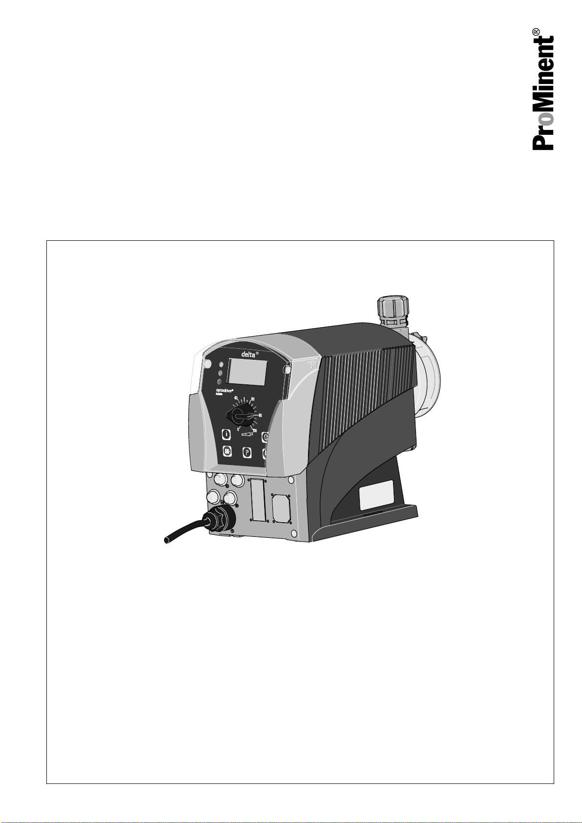
Solenoid Metering Pump
delta®
DLTa
with controlled optoDrive®
solenoid drive
EN
Please carefully read these operating instructions before use. · Do not discard.
The operator shall be liable for any damage caused by installation or operating errors.
The latest version of the operating instructions are available on our homepage.
Original operating instructions (2006/42/EC)Part no. 986691 BA DE 036 08/18 EN
Page 2

Supplemental directives
Supplementary information
Fig. 1: Please read!
Read the following supplementary information in its entirety! You will ben‐
efit more from using the operating instructions should you already know
this information.
The following are highlighted separately in the document:
n Enumerated lists
Instructions
Outcome of the instructions
ð
Ä ‘State the identity code and serial number’ on page 2
in this chapter
- refer to ... : References to points in this document or another document
: Links to points
[Keys]
Information
Validity
State the identity code and serial number
This provides important information relating to the cor‐
rect operation of the unit or is intended to make your
work easier.
Safety Information
Safety information is identified by pictograms - see Safety Chapter.
These operating instructions conform to current EU regulations applicable
at the time of publication.
Please state identity code and serial number, which you can find on the
nameplate when you contact us or order spare parts. This enables us to
clearly identify the unit type and material versions.
2
Page 3

Table of contents
Table of contents
Identity code.................................................................................... 6
1
2 About this pump............................................................................... 9
3 Safety chapter............................................................................... 10
4 Storage, transport and unpacking................................................. 15
5 Overview of equipment and control elements............................... 17
5.1 Overview of equipment......................................................... 17
5.2 Control elements................................................................... 18
5.2.1 Key functions...................................................................... 18
5.2.2 Stroke length adjustment knob........................................... 19
5.2.3 Identifier............................................................................. 19
6 Functional description.................................................................... 22
6.1 Liquid End............................................................................. 22
6.2 Drive unit............................................................................... 22
6.3 Capacity................................................................................ 22
6.4 Operating modes................................................................... 23
6.5 Functions............................................................................... 23
6.6 Relay (options)...................................................................... 24
6.7 Functional and fault Indicator................................................ 24
6.8 LCD display........................................................................... 25
6.9 LED indicators....................................................................... 25
6.10 Hierarchy of operating modes, functions and fault sta‐
tuses....................................................................................
7 Assembly....................................................................................... 26
8 Hydraulic Installation..................................................................... 27
8.1 Installing hose lines............................................................... 28
8.1.1 Installation of metering pumps without bleed valve............ 28
8.1.2 Installation of metering pumps with bleed valve................. 30
8.2 Basic installation notes.......................................................... 31
9 Electrical installation...................................................................... 33
9.1 Supply voltage connector...................................................... 34
9.2 Description of the Terminals................................................. 35
9.2.1 "External control" terminal.................................................. 35
9.2.2 "Level switch" terminal....................................................... 36
9.2.3 "Metering monitor" terminal................................................ 36
9.2.4 "Diaphragm rupture sensor" terminal................................. 37
9.3 Relay..................................................................................... 37
9.3.1 Relay functions................................................................... 37
9.3.2 "Fault indicating relay" output (identity code 1 + 3 or 6 +
7)........................................................................................ 38
9.3.3 Output for other relays (identity code 4 + 5, 8 + 9, A + B).. 39
9.3.4 Output "Current output plus relay" (identity code C + D +
E)........................................................................................ 39
10 Setting........................................................................................... 41
10.1 Basic principles for setting up the control............................ 41
10.2 Checking adjustable variables............................................ 41
10.3 Changing to Setting mode................................................... 42
10.4 Selecting the operating mode (Menu "Mode").................... 43
10.5 Operating mode settings (menu "Settings")........................ 43
10.5.1 "Manual" operating mode settings................................... 45
10.5.2 Settings for the “Batch” operating mode (BATCH
menu)...............................................................................
10.5.3 "Contact" operating mode settings................................... 46
10.5.4 "Analog" operating mode settings.................................... 48
25
45
3
Page 4

Table of contents
10.6 Programmable function settings ("Settings" menu )............ 50
10.6.1 Settings for the “Concentration” function (CONCENTRA‐
TION menu).....................................................................
51
10.6.2 Settings for the “Auxiliary frequency” function (AUX
menu)...............................................................................
58
10.6.3 Settings for the “Flow” function (FLOW menu)................. 59
10.6.4 Settings for the “Calibration” function (CALIBRATION
menu)............................................................................... 59
10.6.5 Settings for the “Metering” function (METERING menu).. 61
10.6.6 Settings for the "Bleeding" function)................................. 65
10.6.7 Settings for the “Relay” function (RELAY menu).............. 67
10.6.8 Settings for the “Analogue output” function (ANALOG
OUTPUT menu)............................................................... 68
10.6.9 Settings in the "System" menu" (SYSTEM menu)........... 69
10.7 Set code (SECURITY menu).............................................. 70
10.8 Delete total number of strokes or total litres (CLEAR
menu).................................................................................. 71
10.9 Set language (LANGUAGE menu)...................................... 71
11 Operation....................................................................................... 72
11.1 Manual................................................................................ 72
11.2 Remote operation................................................................ 74
12 Maintenance.................................................................................. 75
13 Repair............................................................................................ 77
13.1 Cleaning valves................................................................... 78
13.2 Replacing the diaphragm.................................................... 79
13.3 Cleaning the Diaphragm Rupture Indicator......................... 81
14 Troubleshooting............................................................................. 82
14.1 Faults without a fault message............................................ 82
14.2 Fault messages................................................................... 83
14.3 Fault alerts / warning alerts................................................. 83
14.4 Warning messages............................................................. 84
14.5 All other faults..................................................................... 84
15 Decommissioning and disposal..................................................... 85
15.1 Decommissioning................................................................ 85
15.2 Disposal.............................................................................. 86
16 Technical data............................................................................... 87
16.1 Performance data................................................................ 87
16.2 Accuracy............................................................................. 88
16.2.1 Standard liquid ends........................................................ 88
16.3 Viscosity.............................................................................. 88
16.4 Material data....................................................................... 88
16.5 Electrical data...................................................................... 89
16.6 Temperatures...................................................................... 89
16.7 Climate................................................................................ 89
16.8 Degree of Protection and Safety Requirements.................. 90
16.9 Compatibility........................................................................ 90
16.10 Weight............................................................................... 90
16.11 Sound pressure level........................................................ 90
17 Dimensional drawings................................................................... 91
18
Diagrams for setting the metering capacity................................... 95
19 Exploded view drawings................................................................ 97
20 Further order information............................................................. 117
21 EU Declaration of Conformity for Machinery............................... 118
22 Operating menu overview............................................................ 119
4
Page 5

Table of contents
23 Continuous displays.................................................................... 121
24
Index............................................................................................ 123
5
Page 6

Identity code
1 Identity code
product range, version a
delta®
DLTa Type Capacity
bar l/h
2508 25 7.5
1608 16 7.8
1612 16 11.3
1020 10 19.1
0730 7 29.2
0450 4 49.0
0280 2 75.0
Material of dosing head / valves
SS Stainless steel / stainless steel
PV PVDF / PVDF
NP Clear acrylic / PVC
Material of seals / diaphragm
T PTFE / PTFE-coated
S PTFE / Diaphragm also coated with FPM
B FPM-B / PTFE-coated
E EPDM / PTFE-coated
F FDA-compliant
Dosing head design
0 without bleed valve, without valve spring
1 without bleed valve, with valve spring
2 with bleed valve, without valve spring
3 with bleed valve, with valve spring
4 HV version for media of higher viscosity
7 Self-bleeding without bypass (SER)
Hydraulic connector
0 Standard connection in line with technical data
5 Connector for 12/6 hose, suction side standard
F Connector on discharge side for 8/4 hose, standard on suction side
Diaphragm rupture indicator
0 without diaphragm rupture indicator
1 Diaphragm rupture indicator
2 With dual diaphragm system and diaphragm rupture indicator, pres‐
sure sensor
Design
0 with ProMinent logo
Electrical connection
U Universal control 100-230 V ±10%, 50/60 Hz
6
Page 7

product range, version a
delta®
Identity code
Cable and plug
A 2 m European
B 2 m Swiss
C 2 m Australian
D 2 m USA / 115 V
1 2 m open end
... ...
Relay
0 no relay
1 Fault indicating
relay (N/C)
3 Fault indicating
relay (N/O)
1 x changeover con‐
tact 230 V – 8 A
1 x changeover con‐
tact 230 V – 8 A
4 as 1 + pacing relay 2 x N/O 24 V – 100
mA
5 as 3 + pacing relay 2 x N/O 24 V – 100
mA
A Shut-down and
warning relays
2 x N/O 24 V – 100
mA
(N/C)
C As 1 + 4-20 mA
mA output
F With automatic
1 x N/O 24 V – 100
mA
230 V
bleed valve
G with automatic
24 VDC
bleed valve and
relay output
... ...
Accessories
0 no accessories
1 with foot and injection valve, 2 m
suction line, 5 m metering line
2 As 0 + measuring cup
3 As 1 + measuring cup
Control version
0 Manual + external contact
with pulse control
3 Manual + external contact
with pulse control + ana‐
logue 0/4-20mA
4 As 0 + 4-week process
timer
5 As 3 + 4-week process
timer
C As 3 + CANopen
M As 3 + pH, ORP and
chlorine + DFMA control
module
7
Page 8

Identity code
product range, version a
delta®
R
As 3 + PROFIBUS® inter‐
face, M12
Access code
0 No access code
1 With access code
Language
EN German
EN English
FR French
ES Spanish
IT Italian
... ...
Pause / level
0 Pause
N/C, level
N/C
8
Page 9

2 About this pump
About this pump
Properties of the device
The solenoid metering pumps belonging to the delta® product range with
controlled optoDrive® solenoid drive are microprocessor-controlled sole‐
noid metering pumps with the following characteristics:
n Continuous or pulsing operation
n Adaptation of the pump to the feed chemical
n Detection of blocked points of injection, broken metering lines and
trapped air or gas bubbles in the dosing head by the integral injection
point monitor optoGuard.
n Output range 7.5 l/h, 25 - 2 bar
n Stroke length continuously adjustable between 0 - 100 % (recom‐
mended 30 - 100 %)
n Material versions PVDF and stainless steel
n Patented coarse/fine adjustment
n Diaphragm rupture detection and signalling (optional)
n Adjustment and display of the feed rate, either as strokes/min or l/h
via the keyboard
n Large illuminated graphic display
n External activation via potential-free contacts with optional pulse step-
up and step-down
n Option of external activation by standard signal 0/4-20 mA
n Interface for PROFIBUS®or CANopen (optional)
n 14-day process timer* for time- and event-dependent metering tasks
n Connection for 2-stage level switch
n 3 LED display for operation, warning and fault messages in plain text
n Concentration input for volume-proportional metering
n Automatic bleed
n Pump type 2508 with 7.5 l/h at 25 bar
n Material version NP for pump types 2508, 1612, 1608, 1020 and 0730
9
Page 10
Safety chapter
3 Safety chapter
Labelling of safety information
Warning signs denoting different types of
danger
The following signal words are used in these operating instructions to
denote different levels of danger:
Signal word Meaning
WARNING Denotes a possibly hazardous sit‐
uation. If this is disregarded, you
are in a life-threatening situation
and this can result in serious inju‐
ries.
CAUTION Denotes a possibly hazardous sit‐
uation. If this is disregarded, it
could result in slight or minor inju‐
ries or material damage.
The following warning signs are used in these operating instructions to
denote different types of danger:
Warning signs Type of danger
Warning – automatic start-up.
Warning – high-voltage.
Intended use
Warning – danger zone.
n Only use the pump to meter liquid feed chemicals.
n Only use the pump after it has been correctly installed and started up
in accordance with the technical data and specifications contained in
the operating instructions.
n Observe the general limitations with regard to viscosity limits, chem‐
ical resistance and density - see also ProMinent® Resistance List in
the Product Catalogue or at www.prominent.com!
n All other uses or modifications are prohibited.
n The pump is not intended for the metering of gaseous media and
solids.
n The pump is not intended for the metering of explosive media.
n The pump is not intended for operation in areas at risk from explosion.
n The pump is not intended for flammable media without suitable pro‐
tective measures.
n The pump is not intended for exterior applications without the imple‐
mentation of suitable protective measures.
n The pump should only be operated by trained and authorised per‐
sonnel, see the following "Qualifications" table.
n You have a responsibility to adhere to the information contained in the
operating instructions at the different phases of the unit's service life.
10
Page 11

Qualification of personnel
Safety chapter
Action Qualification
Storage, transport, unpacking Instructed person
Assembly Technical personnel, service
Planning hydraulic installation Qualified personnel who have a
thorough knowledge of metering
pumps.
Hydraulic installation Technical personnel, service
Installation, electrical Electrical technician
Operation Instructed person
Maintenance, repair Technical personnel, service
Decommissioning, disposal Technical personnel, service
Troubleshooting Technical personnel, electrical
technician, instructed person,
service
Explanation of the terms:
Technical personnel
A qualified employee is deemed to be a person who is able to assess the
tasks assigned to him and recognise possible dangers based on his/her
technical training, knowledge and experience, as well as knowledge of
pertinent regulations.
Note:
A qualification of equal validity to a technical qualification can also be
gained by several years employment in the relevant work area.
Electrical technician
Electrical technicians are deemed to be people, who are able to complete
work on electrical systems and recognise and avoid possible dangers
independently based on their technical training and experience, as well as
knowledge of pertinent standards and regulations.
Electrical technicians should be specifically trained for the working envi‐
ronment in which they are employed and know the relevant standards and
regulations.
Electrical technicians must comply with the provisions of the applicable
statutory directives on accident prevention.
Instructed person
An instructed person is deemed to be a person who has been instructed
and, if required, trained in the tasks assigned to him/her and possible dan‐
gers that could result from improper behaviour, as well as having been
instructed in the required protective equipment and protective measures.
Service
Customer Service department refers to service technicians, who have
received proven training and have been authorised by ProMinent or Pro‐
Maqua to work on the system.
Safety information
WARNING!
Warning about personal and material damage
The pump can start to pump, as soon as it is connected
to the mains voltage.
– Install an emergency cut-off switch in the pump
power supply line or integrate the pump in the emer‐
gency cut-off management of the system.
11
Page 12
Safety chapter
WARNING!
Danger of electric shock
A mains voltage may exist inside the pump housing.
– If the pump housing has been damaged, you must
disconnect it from the mains immediately. It may
only be returned to service after an authorised
repair.
WARNING!
Fire danger
When pumping inflammable media the operator must
take suitable safety precautions.
WARNING!
Warning of hazardous feed chemical
Should a dangerous feed chemical be used: it may
escape from the hydraulic components when working on
the pump, material failure or incorrect handling of the
pump.
– Take appropriate protective measures before
working on the pump (e.g. safety glasses, safety
gloves, ...). Adhere to the material safety data sheet
for the feed chemical.
–
Drain and flush the liquid end before working on the
pump.
CAUTION!
Warning of feed chemical spraying around
Feed chemical can spray out of the hydraulic compo‐
nents if they are manipulated or opened due to pressure
in the liquid end and adjacent parts of the system.
– Disconnect the pump from the mains power supply
and ensure that it cannot be switched on again by
unauthorised persons.
Depressurise the system before commencing any
–
work on hydraulic parts.
CAUTION!
Warning of feed chemical spraying around
An unsuitable feed chemical can damage the parts of
the pump that come into contact with the chemical.
– Take into account the resistance of the wetted mate‐
rials and the ProMinent Resistance List when
selecting the feed chemical - see the ProMinent
Product Catalogue or visit ProMinent.
12
Page 13
Safety chapter
CAUTION!
Warning of feed chemical spraying around
The metering pump can generate a multiple of its rated
pressure. Hydraulic parts can rupture if a discharge line
is blocked.
– Correctly install a back pressure valve in the dis‐
charge line behind the metering pump.
CAUTION!
Only with SER dosing heads: Warning of feed chemical
spraying around
If there is a high pressure acting on the other side of the
discharge valve, opening of the bleed valve can result in
feed chemical escaping even if the pump is at a stand‐
still.
CAUTION!
Danger of personnel injury and material damage
The use of untested third party parts can result in per‐
sonnel injuries and material damage.
– Only fit parts to metering pumps, which have been
tested and recommended by ProMinent.
CAUTION!
Danger from incorrectly operated or inadequately main‐
tained pumps
Danger can arise from a poorly accessible pump due to
incorrect operation and poor maintenance.
– Ensure that the pump is accessible at all times.
Adhere to the maintenance intervals.
–
CAUTION!
Danger from incorrect metering
Should a different liquid end size be fitted, this will
change the metering behaviour of the pump.
– Have the pump reprogrammed in the works.
CAUTION!
Warning against illegal operation
Observe the regulations that apply where the device is
installed.
Fixed separating protective equipment
n Dosing head
n Housing
n Hood (houses the control elements)
The dosing head may only be removed by the customer in accordance
with the "Repair" chapter.
The housing and the hood may only be removed by ProMinent customer
service department.
13
Page 14

Safety chapter
Information in the event of an emergency
In the event of an electrical accident, disconnect the mains cable from the
mains or press the emergency cut-off switch fitted on the side of the
system!
If feed chemical exits, switch off the pump by pressing the
[Stop/Start]
key.
If necessary depressurise the hydraulic system around the pump. Observe
the safety data sheet for the feed chemical.
Sound pressure level
Sound pressure level LpA < 70 dB according to EN ISO 20361
at maximum stroke length, maximum stroke rate, maximum back pressure
(water)
14
Page 15
4 Storage, transport and unpacking
Safety information
WARNING!
The pump can tip over when lifting
The pump can tip over when lifting, as the centre of
gravity of the pump is quite a distance from the liquid
end.
– Grip the pump quite close to the liquid end.
Safety information
WARNING!
The transporting of pumps which have been used with
radioactive feed chemicals is forbidden!
They will also not be accepted by ProMinent!
Storage, transport and unpacking
WARNING!
Only return metering pumps for repair in a cleaned state
and with a flushed liquid end - refer to "Decommis‐
sioning!
Only return metering pumps with a completed Decon‐
tamination Declaration form. The Decontamination Dec‐
laration constitutes an integral part of an inspection /
repair order. A unit can only be inspected or repaired
when a Declaration of Decontamination Form is sub‐
mitted that has been completed correctly and in full by
an authorised and qualified person on behalf of the
pump operator.
The "Decontamination Declaration Form" can be found
on our homepage.
CAUTION!
Danger of material damage
The device can be damaged by incorrect or improper
storage or transportation!
– The unit should only be stored or transported in a
well packaged state - preferably in its original pack‐
aging.
The packaged unit should also only be stored or
–
transported in accordance with the stipulated
storage conditions.
– The packaged unit should be protected from mois‐
ture and the ingress of chemicals.
Ambient conditions
Refer to the "Technical Data" chapter
15
Page 16

Storage, transport and unpacking
Scope of delivery
Compare the delivery note with the scope of delivery:
n Metering pump with mains cable
n Connector kit for hose/pipe connection
n Product-specific operating instructions with EC Declaration of Con‐
formity
n Optional accessories
n Relay cable, as necessary
16
Page 17
1 2
3
P_DE_0027_SW
P_DE_0019_SW
a
b
c
d
e
f
g
Overview of equipment and control elements
5 Overview of equipment and control elements
Overview of equipment
5.1
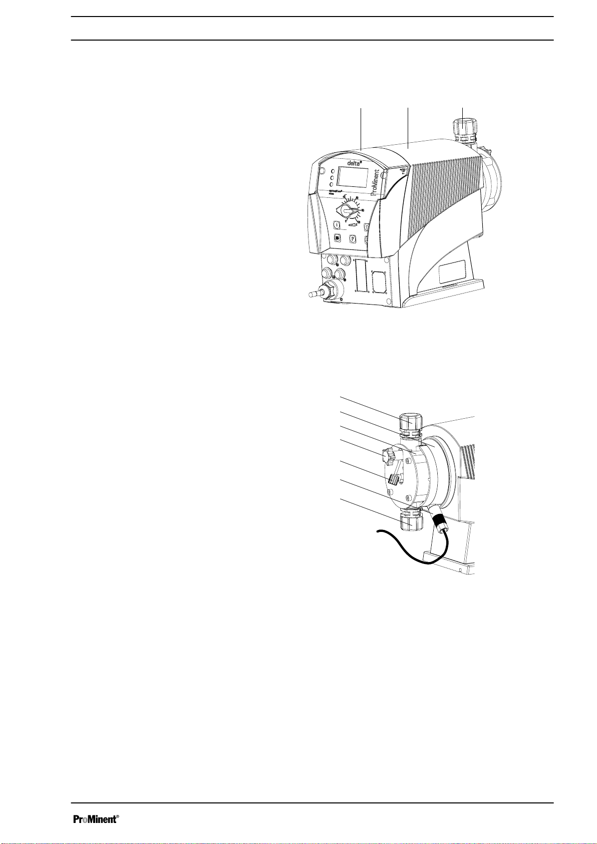
Fig. 2
1 Control unit
2 Drive unit
3 Liquid end
Fig. 3
a Discharge valve
b Backplate
c Dosing head
d Bleed valve
e Bypass hose sleeve
f Diaphragm rupture sensor
g Suction valve
17
Page 18
11 13 15 161412
10
9
8
7
3
1
a)
b)
5
4
2
6
P_DE_0017_SW
STOP
START
P
i
B0098
Overview of equipment and control elements
5.2 Control elements
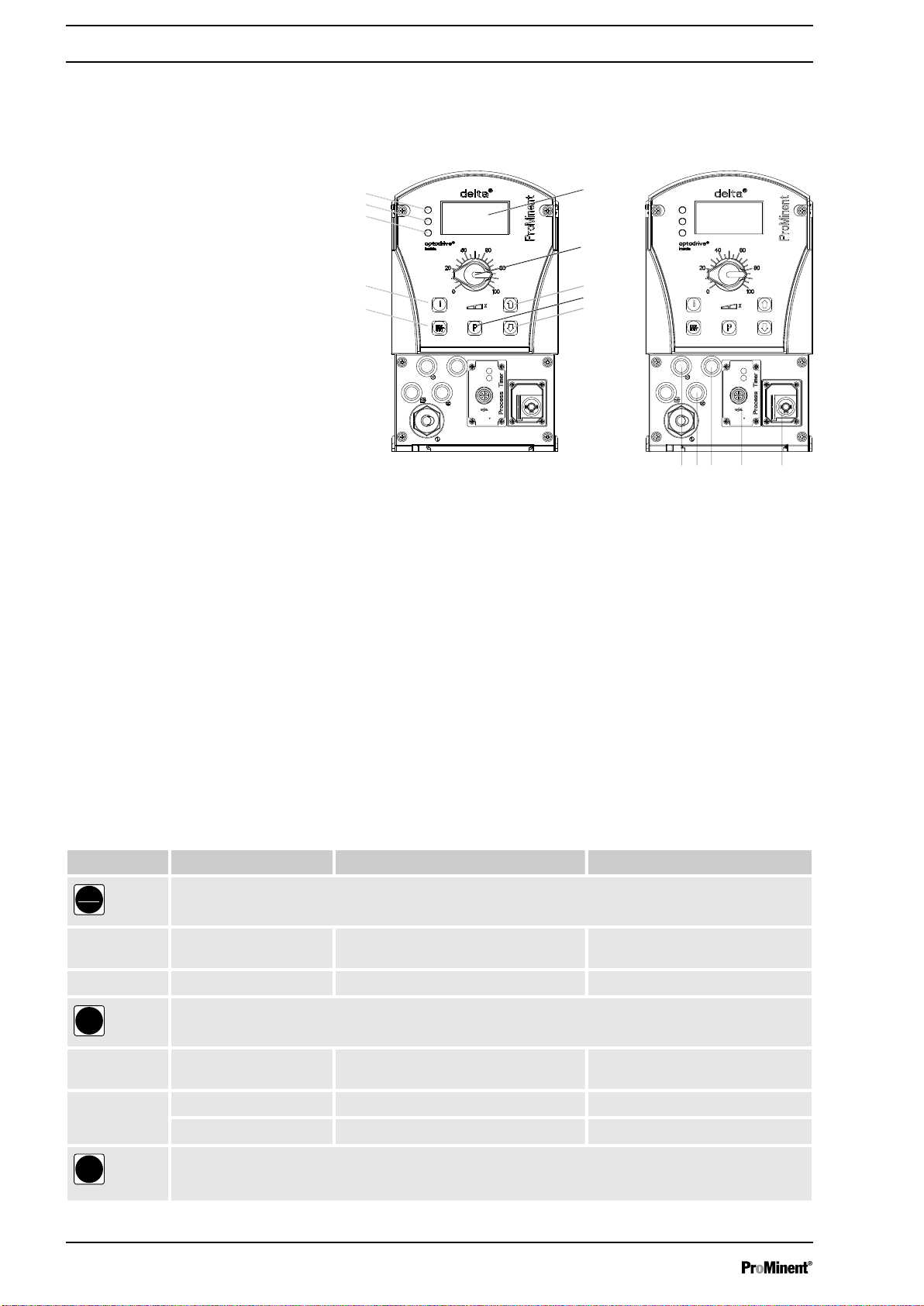
Fig. 4: a)Displays and keys, b) Electrical control connections
1 LCD screen
2 Stroke length adjustment knob
3
[UP]
4
5
6
7
key
[P]
key
[DOWN]
key
[STOP/START]
[i]
key
key
8 Operating indicator (green)
9 Warning indicator (yellow)
10 Fault indicator (red)
11 "External control" socket
12 "Metering monitor" socket
13 "Level switch" socket
14 "Diaphragm rupture indicator" socket
15
Slot for optional modules (timer, PROFIBUS®, CAN-Bus)
16 Relay and mA-output (optional)
5.2.1 Key functions
Key Application In continuous displays (operation) In adjustment mode (set up)
[STOP/
START]
Pressed briefly Stop pump, Stop pump,
Start pump Start pump
[P]
Pressed briefly Start batch (only in
Pressed for 2 s Change to adjustment mode -
Pressed for 3 s - Jump to continuous display
‘Batch’
operating
mode), acknowledge fault
18
Confirm entry - jump to next menu
option or to continuous display
Page 19
P
10548
Analog
200
/min
Stop
Aux
cal
P
ii
Overview of equipment and control elements
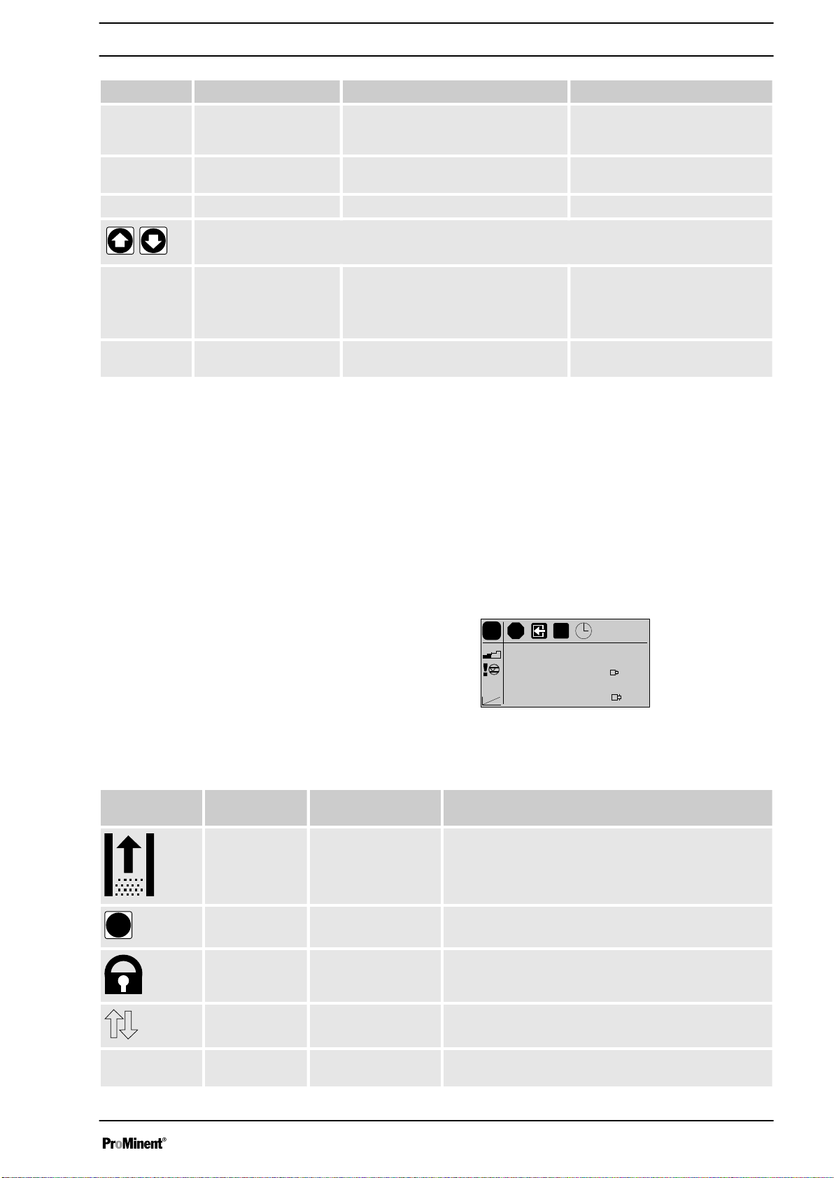
Key Application In continuous displays (operation) In adjustment mode (set up)
[i]
Pressed 2x - Under "change individual digits":
Press and hold Change to the secondary display -
[UP], [DOWN]
Pressed simultaneously Priming (in "Stroke rate" continuous
Pressed 1x Switch between the continuous dis‐
Individually pressed
(until double arrow
appears)
plays
Change directly adjustable variables Select another setting, change
display)
Change between "Change indi‐
vidual digits" and "Change one
number"
Jump to the first digit
individual number or number.
At the top end of a selection,
effect similar to an ESC key.
-
5.2.2 Stroke length adjustment knob
The stroke length can be adjusted using the stroke length adjustment knob
and with it the volume per stroke.
5.2.3
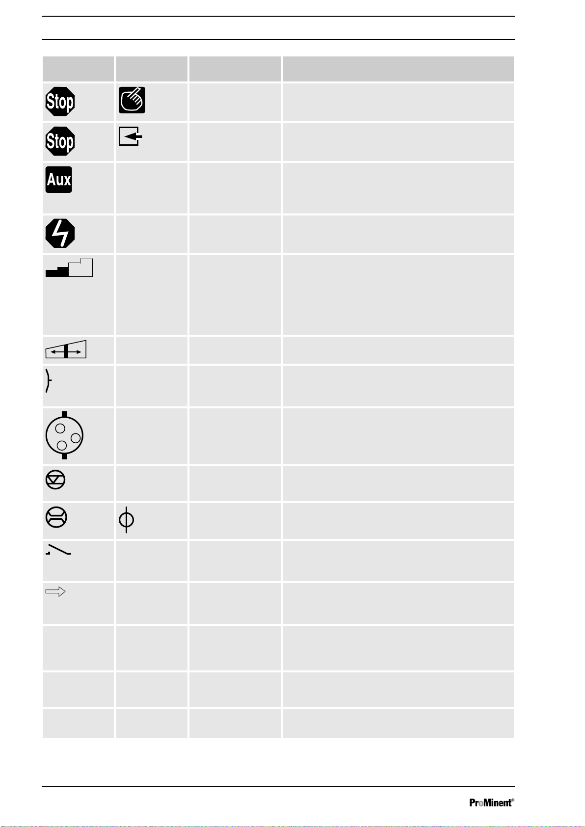
Symbol Additional
Identifier
symbol
Priming: The pump is currently priming (both arrow keys pressed).
Symbol for P-key: The pump is in adjustment mode.
The LCD screen supports the operation and adjustment of the pump using
different identifiers:
Fig. 5
The identifiers have the following meanings:
Name Meaning
Lock symbol: Lock (if a code was set. Flashes).
Double arrow symbol: the value in the continuous display can be changed with
Info symbol: It is possible to change between continuous displays.
the arrow keys.
19
Page 20
p+
p -
mm
Overview of equipment and control elements
Symbol Additional
symbol
Aux: The pump is currently pumping with the auxiliary fre‐
Fault: A fault has occurred, which has stopped the system.
Stroke length: The pump is set to
Stroke length adjust‐
Name Meaning
Stop: The pump was stopped using the
Pause: The pump was externally stopped by the Pause contact.
(therefore manually).
quency as the stroke rate.
During this time, the pump is in
mode.
‘Metering’ ‘slow’
mode is also active (less than 61 strokes/min). Below 30
strokes/min the operating indicator flashes during opera‐
tion and illuminates for slightly longer at the end of each
stroke.
The symbol relates to the symbol, which is located
beneath the stroke adjustment dial.
ment:
Deviation in the stroke length from the value set at the
time of the last locking of the setting menu.
[STOP/START]
‘Manual’
operating
and this metering
key
Diaphragm rupture: The diaphragm is broken. The message appears as a
Air lock: There is air in the liquid end. The message appears as a
Level: The "Warning" level in the storage tank was trans‐
Flow: A flow control is connected. Together with a call sign, the
Contact: The pump is in
Contact signal: The pump is in
Overpressure moni‐
toring:
warning or fault, dependent upon the setting.
The symbol represents a section through the membrane.
warning or fault, dependent upon the setting.
The symbol represents a liquid end with air bubbles in it.
gressed. If the symbol flashes, the level has fallen below
the "Fault" level in the storage tank and the pump stops.
symbol indicates problems with the flow.
‘Contact’
The symbol closes every time a contact signal is gener‐
ated.
‘Batch’
The symbol flashes every time a contact signal is gener‐
ated.
A constriction or a closed shut-off valve on the discharge
side allows the pressure to increase above the maximum
permissible operating pressure. The message appears
as a warning or fault, dependent upon the setting.
operating mode.
operating mode.
Low pressure: There is a leak or a burst or torn line on the discharge
Memory: The pump is in operating mode
side. The message appears as a warning or fault,
dependent upon the setting.
the auxiliary function "Memory" is set.
‘Contact’
20
or
‘Batch’
and
Page 21

0..200..20
4..204..20
i < 4i < 4
i > 23i > 23
Overview of equipment and control elements
Symbol Additional
symbol
0...20 mA: The pump is in operating mode
4...20 mA: The pump is in operating mode
i less than 4 mA: Problems with the standard signal at the standard signal
i greater than 23 mA: The standard signal at the standard signal input indicates
Line: The pump is in operating mode
Upper sideband: The pump is in operating mode
Lower sideband: The pump is in operating mode
Name Meaning
type
‘0...20’
type
‘4...20’
input e.g. broken cable.
a fault with the connected unit.
The processing type
The processing type
type
‘Curve’-‘Lower sideband’
The pump only shows the metering volume and the
capacity in the calibrated state in l or l/h or in gal or
gal/h.
is set.
is set.
‘Analog’
‘Analog’
‘Analog’
‘Curve’-‘Linear’
‘Analog’
‘Curve’-‘Upper sideband’
‘Analog’
is set.
. The processing
. The processing
.
is set.
.
. The processing
is set.
21
Page 22
P_DE_0006_SW
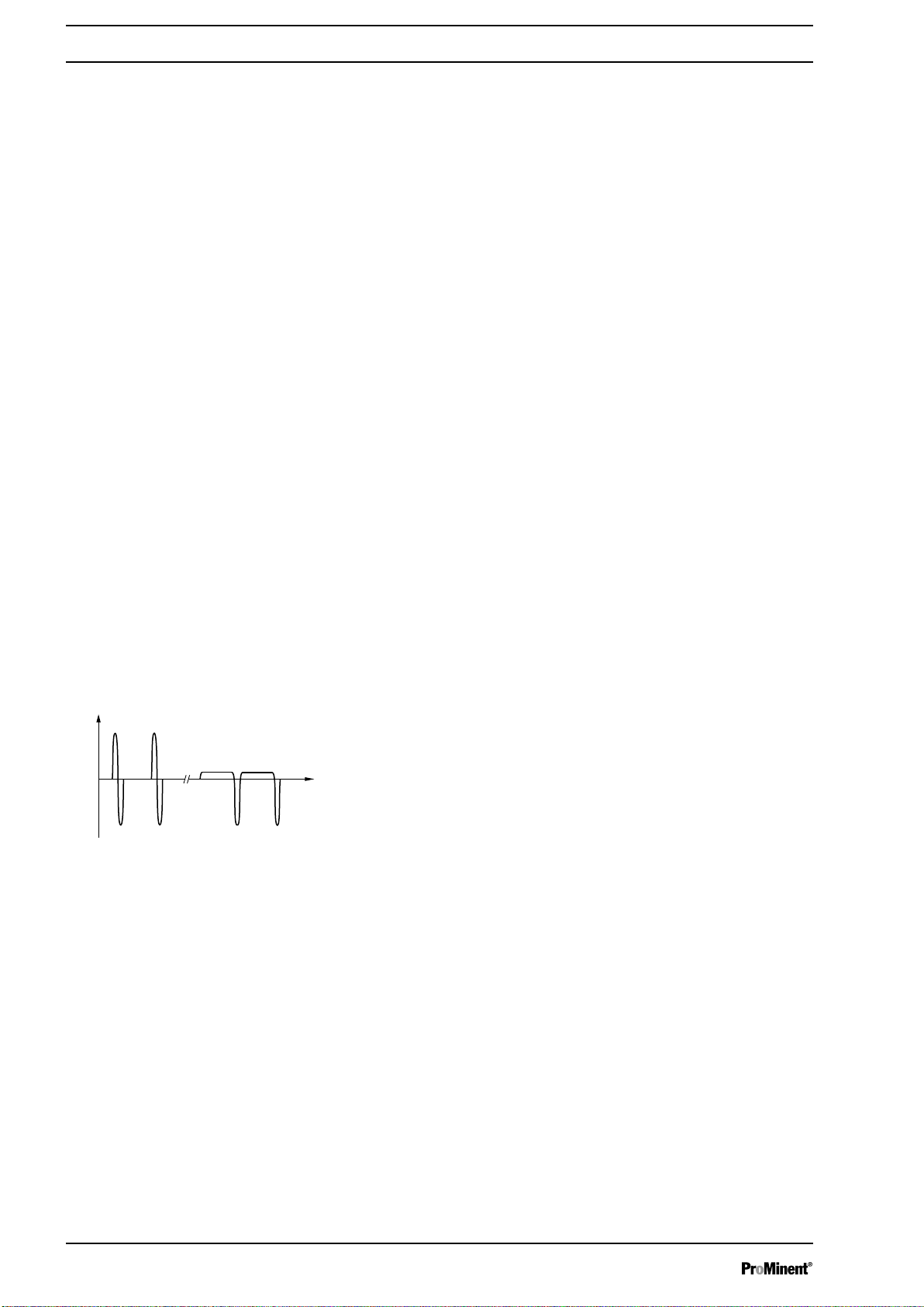
p
a) b)
t
Functional description
6 Functional description
Liquid End
6.1
The dosing process is performed as follows: The diaphragm is pressed
into the dosing head; the pressure in the dosing head closes the suction
valve and the feed chemical flows through the discharge valve out of the
dosing head. The diaphragm is now drawn out of the dosing head; the dis‐
charge valve closes due to the negative pressure in the dosing head and
fresh feed chemical flows through the suction valve into the dosing head.
One cycle is completed.
6.2 Drive unit
The displacement body is driven by an electromagnet, which is controlled
by an electronic control.
optoDrive® drive technology
Fig. 6: Metering types: a) pulsing, b)
nearly continuous
The optoDrive® drive technology means the variation over time of the
metering flow can be precisely matched to the requirements of the partic‐
ular application. Hence the user can, dependent on requirements, set a
slow discharge stroke for nearly continuous metering or a quick stroke e.g.
for quick clocked filling processes. In both operating modes it is possible,
to selectively also slow the suction stroke, see figure. In this way, it is pos‐
sible to prevent the main cause for imprecise metering with high viscosity
feed chemicals, namely the incomplete filling of the liquid end. For the
case of gaseous feed chemicals, the slow suction stroke prevents cavita‐
tion and consequently increases metering accuracy. Oscillations in the
back pressure in the metering line, which could lead to undesirable varia‐
tions in the metering volume, are automatically compensated for by the
drive. Consequently, a dosing precision is attained, which otherwise could
only be achieved using a complex control circuit.
p Pressure
t Time
The integral injection point monitoring of the hydraulic metering parame‐
ters, optoGuard® is integrated in the drive. It automatically detects blocked
points of injection or broken metering lines. Consequently, dependent on
the hydraulic installation situation, separate relief valves and pressure sen‐
sors need not be used, and no uncontrolled metering through a broken
line occurs. It also detects air or gases (airlock) trapped in the liquid end.
This prevents metering of incorrect quantities and thus increases process
reliability. The relevant messages are shown on the pump's display. The
system operator can determine, depending on the type of fault, whether a
message is to be sent to the process control system via the fault signal
relay and whether metering is automatically stopped.
6.3
Capacity
The capacity is determined by the stroke length and rate.
22
Page 23

6.4 Operating modes
Functional description
The stroke length is adjusted by the stroke length adjustment knob within
a range of 0 ... 100 %. A stroke length of between 30 ... 100 %) is recom‐
mended to achieve the specified reproducibility.
The stroke rate can be set using the arrow keys (not in "Analog" operating
mode) in the range 0 - 200 strokes/min (200 strokes/min
strokes/h). The "Stroke rate (strokes / min)" continuous display shows dec‐
imal places if a stroke frequency is set in the "Stroke rate (strokes / h)"
continuous display, which cannot be divided by 60 without a remainder.
Data Value Unit
Recommended stroke length 30 ... 100 %
The stroke speed can be set in the "Dosing" menu.
Operating modes are selected via the "Operating modes" menu.
≜12,000
"Manual" operating mode
"Batch" operating mode
Operating mode "Contact"
"Analog" operating mode
6.5 Functions
"Calibrate" function
The stroke rate is set manually via the control unit.
This operating mode provides the option of working with large transfer fac‐
tors (up to 65535). Metering can be triggered by pressing the button
by a pulse received via the "External control" jack through a contact or a
semiconductor switching element. A metering volume (batch) or a number
of strokes can be selected in the
This operating mode offers the option of activating the pump externally by
means of potential-free contacts (e.g. by means of a contact water gauge).
The number of strokes (reducing or transfer factor 0.01 to 99.99) can be
pre-selected in the
The stroke rate is controlled using an analog current signal via the
"External control" jack. Processing of the current signal can be preselected
via the control unit.
The following functions can be selected vin the menu
The stroke rate is controlled using an analog current signal via the
"External control" jack. Processing of the current signal can be preselected
via the control unit.
The pump can also be operated in the calibrated state in all operating
modes. The corresponding continuous displays can then either display the
metering volume or the capacity (in the 2nd level continuous display). The
calibration remains valid over the entire stroke rate range and over a
stroke length range from 0 - 100 %.
‘Settings’
‘Settings’
menu using the
menu using the
[arrow keys]
‘Settings’
[arrow keys]
.
[P]
or
.
:
"Auxiliary rate" function
"Flow" function
This enables switching to an adjustable stroke rate which can be fixed in
the
‘Settings’
quency has priority over the operating mode stroke rate settings .
This monitors the flow in "pulsing" dosing mode after every individual
stroke, if a dosing monitor is connected. The number of sequential faulty
strokes above which it is to be stopped, can be set in the
menu via the "External control" jack. This auxiliary fre‐
‘Settings’
23
menu.
Page 24

Functional description
The following functions are available as standard:
"Level switch" function
"Pause" function
"Stop" function
"Priming" function
6.6 Relay (options)
"Fault indicating relay" option
Information about the liquid/powder level in the feed chemical container is
reported to the pump. To do so, a two-stage level switch must be fitted; it
is connected to the "Level switch" jack.
The pump can be remotely stopped via the "External control" jack.
The following functions are triggered by a key press:
The pump can be stopped by pressing the key
disconnecting it from the power supply.
Priming (short-term transport at maximum frequency) can be triggered by
simultaneous pressing of the two
The pump has several connection options for:
The relay can, in the event of fault or warming alerts or messages (e.g.
‘Warning level’
The relay can be retrofitted through a knock-out opening in the pump foot refer to "Retrofitting relays".
), close a connected electric circuit (e.g. for an alarm horn).
[arrow keys]
[STOP/START]
.
, without
"Fault indicating and pacing relay" option
"Automatic bleed" option
"mA output" option
6.7
Functional and fault Indicator
This combined relay can generate a contact with each stroke via its pacing
relay in addition to its function as a fault indicating relay.
The relay can be retrofitted through a knock-out opening in the pump foot refer to "Retrofitting relays".
The function "Bleeding" is used for controlled bleeding of the liquid end, if
the pump is provided with the option "Automatic bleed". The "Automatic
bleed" option can be retrofitted, i.a. via a knock-out in the control unit.
There are two versions:
n version with only 1 relay - to control the bleed valve.
n Version with only 2 relays - one relay to control the bleed valve and
one relay free for other uses.
The I signal of the current output signals the currently calculated pump
metering volume. The option "mA output" can be retrofitted via a knock-out
in the control unit.
The option additionally always provides a fault indicating relay or a pacing
relay.
The operating and fault statuses are indicated by the three LED indicators
and the "Fault" identifier of the LCD screen, see also the "Troubleshooting"
chapter.
24
Page 25

6.8 LCD display
LED indicators
6.9
Fault indicator (red)
Functional description
If a fault occurs, the identifier "Fault" appears as well an additional, explan‐
atory symbol.
The fault indicator lights up if the liquid level in the chemical feed container
falls below the second switching point of the level switch (
filling level in the chemical feed container).
This LED flashes in the event of an undefined operating mode.
20 mm residual
Warning indicator (yellow)
Operating indicator (green)
6.10
Hierarchy of operating modes, functions and fault statuses
The warning indicator lights up if the fluid level in the chemical feed con‐
tainer falls below the first switching point of the level switch.
The operating indicator lights up if the pump is ready for operation and
there are no fault or warning alerts. It goes out quickly as soon as the
pump has performed a stroke. It starts to flash as soon as the stroke rate
falls below 30 strokes / min.
The different operating modes, functions and fault statuses have a dif‐
ferent effect on if and how the pump reacts.
The following list shows the order:
1. - Priming
2. - Fault, Stop, Pause
3. - Auxiliary rate
4. - Manual, Analog, Contact, Batch
Comments:
re 1 - "Priming" can take place in any mode of the pump (providing it is
functioning).
re 2 - "Fault", "Stop" and "Pause" stop everything apart from "Priming".
re 3 - The stroke rate of "Auxiliary rate" always has priority over the
stroke rate specified by an operating mode or priority 4.
25
Page 26
Assembly
7 Assembly
Compare the dimensions on the dimension sheet
–
with those of the pump.
WARNING!
Danger of electric shock
If water or other electrically conducting liquids penetrate
into the drive housing, in any other manner than via the
pump's suction connection, an electric shock may occur.
– Position the pump so that it cannot be flooded.
CAUTION!
Danger from incorrectly operated or inadequately main‐
tained pumps
Danger can arise from a poorly accessible pump due to
incorrect operation and poor maintenance.
– Ensure that the pump is accessible at all times.
Adhere to the maintenance intervals.
–
Capacity too low
The liquid end valves can be disturbed by vibrations.
–
Secure the metering pump so that no vibrations can
occur.
Capacity too low
If the valves of the liquid end are not vertical, they
cannot close correctly.
–
Suction and discharge valves must stand vertically
upwards (for self-bleeding liquid end, the bleed
valve).
Mount the metering pump with the pump foot on a horizontal, level
and load-bearing supporting surface.
26
Page 27
8 Hydraulic Installation
Safety information
Hydraulic Installation
CAUTION!
Warning of feed chemical spraying around
An unsuitable feed chemical can damage the parts of
the pump that come into contact with the chemical.
– Take into account the resistance of the wetted mate‐
rials and the ProMinent Resistance List when
selecting the feed chemical - see the ProMinent
Product Catalogue or visit ProMinent.
CAUTION!
Warning of feed chemical spraying around
Pumps which are not fully installed hydraulically can
eject feed chemicals from the outlet openings of the dis‐
charge valves as soon as they are connected to the
mains.
– The pump must first be hydraulically installed and
then electrically.
– In the event that you have failed to do so, press the
[STOP/START]
switch.
button or press the emergency-stop
CAUTION!
Warning of feed chemical spraying around
Feed chemical can spray out of the hydraulic compo‐
nents if they are manipulated or opened due to pressure
in the liquid end and adjacent parts of the system.
– Disconnect the pump from the mains power supply
and ensure that it cannot be switched on again by
unauthorised persons.
–
Depressurise the system before commencing any
work on hydraulic parts.
CAUTION!
Danger from rupturing hydraulic components
Peak loads during the dosing stroke can cause the max‐
imum permissible operating pressure of the system and
pump to be exceeded.
– The discharge lines are to be properly designed.
CAUTION!
Danger of personnel injury and material damage
The use of untested third party parts can result in per‐
sonnel injuries and material damage.
– Only fit parts to metering pumps, which have been
tested and recommended by ProMinent.
27
Page 28
Hydraulic Installation
8.1 Installing hose lines
8.1.1
Safety information
Installation of metering pumps without bleed valve
CAUTION!
Warning of feed chemical spraying around
The pipes can loosen or rupture if they are not installed
correctly.
– Route all hose lines so they are free from mechan‐
ical stresses and kinks.
Only use original hoses with the specified hose
–
dimensions and wall thicknesses.
– Only use clamp rings and hose nozzles that are
intended for the hose diameter in question to ensure
the long service life of the connections.
CAUTION!
Danger from rupturing hydraulic components
Hydraulic components can rupture if the maximum per‐
missible operating pressure is exceeded.
– Always adhere to the maximum permissible oper‐
ating pressure of all hydraulic components - please
refer to the product-specific operating instructions
and system documentation.
–
Never allow the metering pump to run against a
closed shut-off device.
– Install a relief valve.
CAUTION!
Hazardous feed chemicals can escape
Hazardous or extremely aggressive feed chemicals can
escape outside when using conventional bleeding proce‐
dures with metering pumps.
– Install a bleed line with return line into the storage
tank.
CAUTION!
Hazardous feed chemicals can escape
Hazardous or extremely aggressive feed chemicals can
escape outside in the event that the metering pump is
removed from the installation.
– Install a shut-off valve on the pressure and dis‐
charge side of the metering pump.
CAUTION!
Uncontrolled flow of feed chemical
Feed chemical can press through a stopped metering
pump if there is back pressure.
– Use an injection valve or a vacuum breaker.
28
Page 29
Installing hose lines - PP, NP, PV, TT
designs
Hydraulic Installation
CAUTION!
Uncontrolled flow of feed chemical
The feed chemical can leak through the metering pump
in an uncontrolled manner in the event of excessive pri‐
ming pressure.
– Do not exceed the maximum priming pressure for
the metering pump - please refer to the product-spe‐
cific operating instructions.
Align the pipes so that the metering pump and the liquid
end can be removed from the side if necessary.
1. Cut off the ends of the hoses at right angles.
2. Pull the union nut (2) and clamp ring (3) over the hose (1) - see .
3. Push the hose end (1) up to the stop over the nozzle (4) and widen,
if necessary.
Ensure that the O-ring and/or the flat seal (5) is
sitting properly in the valve (6).
Never re-use used PTFE seals. An installation
sealed in this way is not watertight.
This type of seal is permanently distorted when
subjected to pressure.
The FPM flat seal PV design has a dot to enable it
to be distinguished from the EPDM flat seal.
4. Place the hose (1) with the nozzle (4) onto the valve (6).
5. Clamp the hose connector: Tighten the union nut (2) while simulta‐
neously pressing on the hose (1).
6. Re-tighten the hose connector: Pull on the hose (1) briefly, which is
fastened to the dosing head and then tighten the union nut (2) once
more.
29
Page 30
1
2
4
5
6
3
P_MAZ_0021_SW
1
2
4
5
3
P_MAZ_0022_SW
Hydraulic Installation
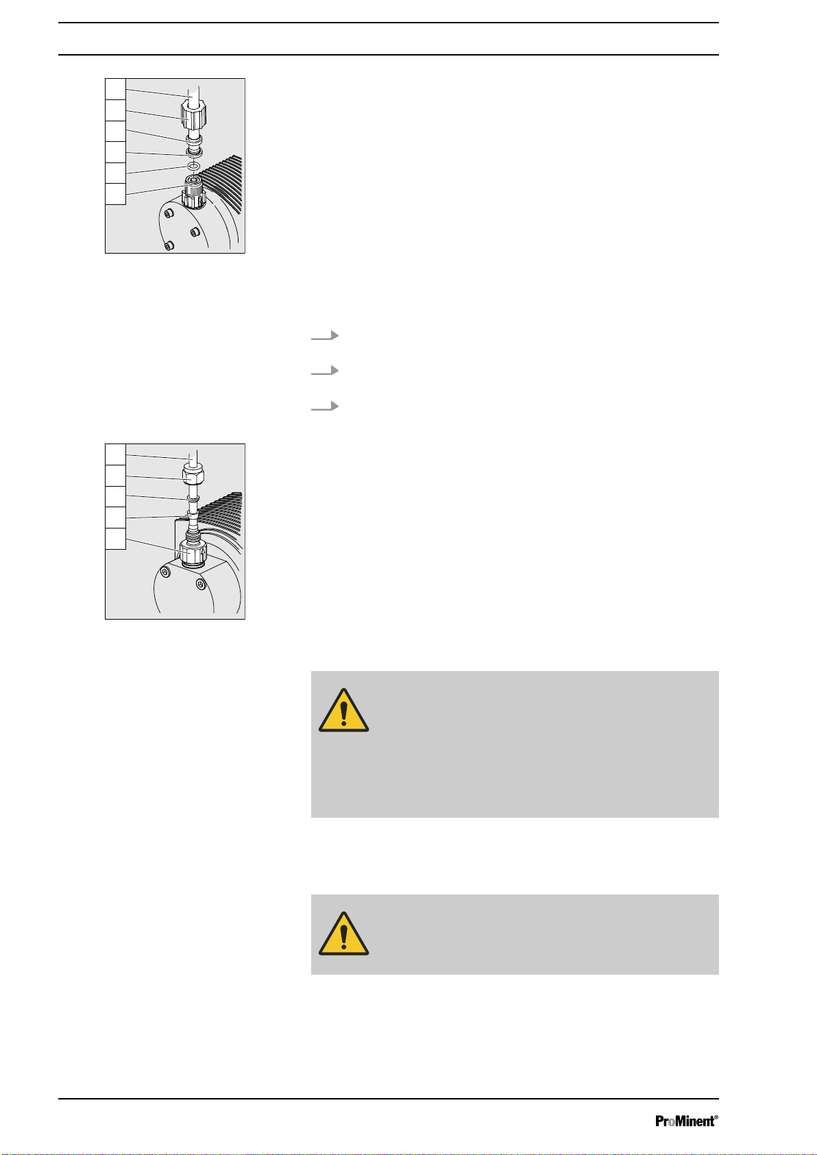
Fig. 7: PP, NP, PV and TT designs
Installing stainless steel pipe - SS design
1 Hose
2 Union nut
3 Clamp ring
4 Nozzle
5 O-ring or flat seal
6 Valve
1. Pull the union nut (2) and clamp rings (3, 4) over the pipe (1) with
approx. 10 mm overhang - see .
2. Insert the pipe (1) up to the stop in the valve (5) and then withdraw
1...2 mm.
3. Tighten the union nut (2).
Fig. 8: SS design
Installing hose lines - SS design
1 Pipe
2 Union nut
3 Rear clamp ring
4 Front clamp ring
5 Valve
CAUTION!
Warning of feed chemical spraying around
Connections can come loose in the event that hose lines
are installed incorrectly on stainless steel valves.
– Only use PE or PTFE hose lines.
In addition, insert a stainless steel support insert into
–
the hose line.
8.1.2 Installation of metering pumps with bleed valve
Safety information
CAUTION!
– All the installation and safety information for
metering pumps without bleed valves also apply.
Installation of the return line
A return line is also connected in addition to the suction and discharge
line.
30
Page 31

8.2
P_MAZ_0001_SW
2
1
Basic installation notes
Safety notes
Hydraulic Installation
1. Attach the hose line to the return hose nozzle or to the liquid end
bleed valve. PVC hose, soft, 6x4 mm is recommended.
2. Feed the free end of the return line into the storage tank.
3. Shorten the return line so that it is not immersed in the feed chem‐
ical in the storage tank.
CAUTION!
Danger resulting from rupturing hydraulic components
Hydraulic components can rupture if the maximum per‐
missible operating pressure is exceeded.
– Never allow the metering pump to run against a
closed shut-off device.
With metering pumps without integral relief valve:
–
Install a relief valve in the discharge line.
CAUTION!
Hazardous feed chemicals can escape
With hazardous feed chemicals: Hazardous feed chem‐
ical can leak out when using conventional bleeding pro‐
cedures with metering pumps.
– Install a bleed line with a return into the storage
tank.
Shorten the return line so that it does not dip into the feed chemical
in the storage tank.
Fig. 9: Standard installation
1 Main line
2 Storage tank
31
Page 32

Hydraulic Installation
Legend for hydraulic diagram
Symbol Explanation Symbol Explanation
Metering pump Foot valve with filter meshes
Injection valve Level switch
Multifunctional valve Manometer
32
Page 33

9 Electrical installation
Electrical installation
WARNING!
Danger of electric shock
A mains voltage may exist inside the device.
– Before any work, disconnect the device's mains
cable from the mains.
WARNING!
Risk of electric shock
This pump is supplied with a grounding conductor and a
grounding-type attachment plug.
– To reduce the risk of electric shock, ensure that it is
connected only to a proper grounding-type recep‐
tacle.
WARNING!
Risk of electric shock
In the event of an electrical accident, the pump must be
quickly disconnected from the mains.
– Install an emergency cut-off switch in the pump
power supply line or
–
Integrate the pump in the emergency cut-off man‐
agement of the system and inform personnel of the
isolating option.
WARNING!
Danger of electric shock
Incompletely installed electrical options can allow mois‐
ture into the inside of the housing.
– Knock-out openings in the pump housing must be
equipped with matching modules or be sealed in a
leak-tight manner.
WARNING!
Danger of electric shock
A mains voltage may exist inside the pump housing.
– If the pump housing has been damaged, you must
disconnect it from the mains immediately. It may
only be returned to service after an authorised
repair.
CAUTION!
Risk of short circuiting caused by moist pins
No moisture must reach the pins of the PROFIBUS
jack.
– A suitable PROFIBUS® plug or protective cap must
be screwed onto the PROFIBUS®
jack.
®
33
Page 34

Electrical installation
CAUTION!
Material damage possible due to power surges
Should the pump be connected to the mains power
supply in parallel to inductive consumers (such as sole‐
noid valves, motors), inductive power surges can
damage the control when it is switched off.
– Provide the pump with its own contacts (Phase) and
supply with voltage via a contactor relay or relay.
Should this not be possible, then switch a varistor
–
(part no. 710912) or an RC gate (0.22 µF/220 Ω,
part no. 710802) in parallel.
CAUTION!
Bonding of the contacts of your switching relay
The high starting current can cause the contacts of the
on-site switching relay to bond together if the mains
voltage switches a solenoid metering pump on and off in
a process.
– Use the switching options offered by the external
socket to control the pump (functions: Pause, Auxil‐
iary frequency or Operating modes: Contact, Batch,
Analogue).
–
Use a starting current limiter if it is impossible to
avoid switching the pump on and off via a relay.
9.1
Supply voltage connector
Personnel:
Install the pump in line with best working practice and in accordance
with the operating instructions and applicable regulations.
WARNING!
Unexpected start-up is possible
The pump can start pumping and consequently feed
chemical may escape as soon as the pump is connected
to the mains/power supply.
– Avoid the escape of feed chemical.
–
If you have not done so, immediately press
[STOP/START]
mains voltage e.g. using an Emergency Stop switch.
– Refer to the material safety data sheet for your feed
chemical.
CAUTION!
If the pump is integrated into a system: Design the
system so that potential hazardous situations are
avoided by pumps starting up automatically subsequent
to unintended power interruptions.
n
Electrician
or disconnect the pump from the
Connect the pump to the mains/power supply using the mains cable.
34
Page 35

9.2 Description of the Terminals
1
54
2
3
P_BE_0014_SW
2
45
1
3
P_BE_0015_SW
Electrical installation
9.2.1
"External control" terminal
Fig. 10: Pump assignment
The "external control" socket is a five-pin panel socket. It is compatible
with two- and four-pole cables.
Only use a five-pole cable with the "Auxiliary frequency" and "mA-input"
functions.
Electrical interface for pin 1 "Pause" - pin 2 "External contact" - pin 5 "Aux‐
iliary frequency"
Data Value Unit
Voltage with open contacts 5 V
Input resistance 10 kΩ
Max. pulse frequency 25 pulse/s
Min. pulse duration 20 ms
Control via:
n potential-free contact (load: 0.5 mA at 5 V) or
n Semiconductor switch (residual voltage < 0.7 V)
Electrical interface for pin 3 "mA input" (with identity code characteristic
"Control version": 3, 5 and R)
Data Value Unit
1
Fig. 11: Cable assignment
"Pause" function
Input apparent ohmic resistance, approx. 120 Ω
1
The metering pump makes its first metering stroke at approx. 0.4 mA (4.4
mA) and starts continuous operation at approx. 19.2 mA.
Pin Operation 5-wire cable 2-wire cable
1 Pause brown bridged at pin 4
2 External contact white brown
3 mA input* blue -
4 Earth GND black white
5 Auxiliary frequency grey -
* with identity code characteristic "Control version": 3, 5 and R
Refer to the functional description for the hierarchy of
functions and operating modes.
The pump does not work if:
n the cable is connected and pin 1 and pin 4 are open.
The pump works if:
n the cable is connected and pin 1 and pin 4 are connected.
n no cable is connected.
35
Page 36

3
21
P_BE_0016_SW
3
12
P_BE_0017_SW
Electrical installation
Acknowledge fault with ‘Pause’
Certain errors requiring acknowledgement can also be
acknowledged using ‘Pause’ instead of using the [P]
key. These are errors like: ‘Flow’ , ‘Air lock’ , ‘ p-’ (as
soon as the conditions are in order).
"External contact" operating mode
"Auxiliary frequency" operating mode
9.2.2 "Level switch" terminal
Fig. 12: Pump assignment
The pump performs one or more strokes if:
n Pin 2 and pin 4 are connected to each other for at least 20 ms. At the
same time, pin 1 and pin 4 must also be connected to each other.
The pump works at a pre-set stroke rate if:
n Pin 5 and pin 4 are connected to each other. At the same time, pin 1
and pin 4 must also be connected to each other. The auxiliary fre‐
quency is factory-preset to the maximum stroke rate.
There is a connecting option for a 2-stage level switch with pre-warning
and limit stop.
Electrical interface
Data Value Unit
Voltage with open contacts 5 V
Input resistance 10 kΩ
Control via:
n potential-free contact (load: 0.5 mA at 5 V) or
n Semiconductor switch (residual voltage < 0.7 V)
Pin Operation 3-wire cable
1 Earth GND black
2 Minimum pre-warning blue
3 Minimum limit stop brown
Fig. 13: Cable assignment
9.2.3 "Metering monitor" terminal
There is a connection option for a dosing monitor.
Electrical interface
36
Page 37

Data Value Unit
1
4
2
3
P_DE_0009_SW
1
4
2
3
P_DE_0010_SW
2
1
3
4
P_DE_0011_SW
2
1
3
4
P_DE_0012_SW
Voltage with open contacts 5 V
Input resistance 10 kΩ
Control via:
n potential-free contact (load: 0.5 mA at 5 V) or
Fig. 14: Pump assignment
Pin Operation 4-wire cable
1 Power supply (5 V) brown
2 Coding white
3 Feedback blue
4 Earth GND black
Fig. 15: Cable assignment
9.2.4 "Diaphragm rupture sensor" terminal
There is a connecting option for a diaphragm rupture sensor.
Electrical installation
Electrical interface
Data Value Unit
Voltage with open contacts 5 V
Input resistance 10 kΩ
Control via:
n potential-free contact (load: 0.5 mA at 5 V) or
Fig. 16: Pump assignment
Pin Operation 4-wire cable
1 Power supply (5 V) brown
2 Coding white
3 Feedback blue
4 Earth GND black
Fig. 17: Cable assignment
9.3 Relay
9.3.1
Tab. 1: delta DLTa
Identity code Description Type Maximum voltage Maximum cur‐
Relay functions
rent
Behaviour of relay
type when retrofit‐
ting, as standard
0 no relay - - - -
1 Fault indicating
3 Fault indicating
relay
relay
NC changeover
contact
NO changeover
contact
230 V 8 A X
230 V 8 A -
37
Page 38

2
3
1
4
P_SI_0010_SW
Electrical installation
Identity code Description Type Maximum voltage Maximum cur‐
rent
Behaviour of relay
type when retrofit‐
ting, as standard
4 Fault indicating
N/O 24 V 100 mA X
relay
Pacing relay N/O 24 V 100 mA -
5 Fault indicating
N/O 24 V 100 mA -
relay
Pacing relay N/O 24 V 100 mA -
A Cut-off relay N/O 24 V 100 mA -
Warning relay N/O 24 V 100 mA -
C fault indicating relay
N/O 24 V 100 mA X
+ 4-20 mA output
Tab. 2: Relay type switches in the event of...
Relay type* Level
warning
Level
low
Metering mon‐
itor
Error
Calibrated
stroke length
Error
Processor
Error
Fault indicating relay: X X X X X
Warning relay: X - - X -
Cut-off relay: - X X - X
* Can be reprogrammed in the
‘Relay’
menu.
9.3.2 "Fault indicating relay" output (identity code 1 + 3 or 6 + 7)
A fault indicating relay can optionally be ordered - refer to ordering infor‐
mation in the appendix. It is used to emit a signal when there is a fault with
the pump and for the "Liquid level low, 1st stage" warning message and
"Liquid level low 2nd stage" fault message.
A cut-off relay works when there are fault alerts from the pump and in the
event of the "Liquid level low 2nd stage" alert.
The fault indicating relay can be retrofitted and is operational once
attached to the relay board - refer to "Retrofitting Relays" supplementary
operating instructions.
The behaviour is factory-programmed. If another switching function is
required, the pump can be reprogrammed in the
The relay can be retrofitted and is operational once it has been plugged
into the relay board.
Electrical interface
Data Value Unit
‘Relay’
menu.
Fig. 18: Pump assignment
Maximum contact load at 230 V and 50/60
8 A
Hz:
Minimum mechanical service life: 200,000 switching
operations
38
Page 39

Identity code 1 + 3 or 6 + 7
P_SI_0043
2
3
1
4
P_SI_0010_SW
P_SI_0044
To pin VDE cable Contact CSA cable
1 white NO (normally open) white
2 green NC (normally closed) red
4 brown C (common) black
Fig. 19: Cable assignment
9.3.3 Output for other relays (identity code 4 + 5, 8 + 9, A + B)
A fault indicating and a pacing relay can optionally be ordered - refer to
ordering information in the appendix. The pacing output is electrically-iso‐
lated by means of an optocoupler with a semiconductor switch. The
second switch is a relay.
The behaviour is factory-programmed. If another switching function is
required, the pump can be reprogrammed in the
The fault indicating/pacing relay can be retrofitted and is operational once
attached to the relay board - refer to the "Retrofitting Relays" supplemen‐
tary instructions.
Electrical installation
‘Relay’
menu.
Fig. 20: Pump assignment
Identity code 4 + 5, 8 + 9, A + B
Electrical interface
for fault indicating relay output:
Data Value Unit
Maximum contact load at 24 V and 50/60
2 A
Hz:
Minimum mechanical service life: 20,000,000 switching
operations
for semiconductor switch pacing relay:
Data Value Unit
Max. residual voltage at I
= 1 µA 0.4 V
off max
Maximum current 100 mA
Maximum voltage 24 VDC
Pacing pulse duration, approx. 100 ms
To pin VDE cable Contact Relay
1 yellow NO (normally open) other relay
4 green C (common) other relay
3 white NO (normally open) Pacing relay
Fig. 21: Cable assignment
2 brown C (common) Pacing relay
9.3.4 Output "Current output plus relay" (identity code C + D + E)
A relay combined with a current output can optionally be ordered. The
relay either switches off the pump as a fault indicating relay in the event of
a fault on the pump and with "Liquid level low 1st stage" warning message
and "Liquid level low 2nd stage" fault messages or is used as a pacing
relay.
39
Page 40

2
3
1
4
P_SI_0010_SW
P_SI_0044
Electrical installation
The behaviour is factory-programmed. If another switching function is
required, the pump can be reprogrammed in the
‘Relay’
menu.
The variable to be signalled for the current output can be selected in the
‘ANALOGUE OUTPUT’
menu.
The current output plus relay can be retrofitted and operates once it is
plugged into the board.
Electrical interface
for current output
Data Value Unit
Open circuit voltage: 8 V
Current range: 4 ... 20 mA
Ripple, max.: 80 μA ss
Fig. 22: Pump assignment
Identity code C + D + E
Fig. 23: Cable assignment
Load, max.: 250 Ω
for semiconductor switch ("relay"):
Data Value Unit
Max. residual voltage at I
= 1 µA 0.4 V
off max
Maximum current 100 mA
Maximum voltage 24 VDC
Pacing pulse duration, approx. 100 ms
To pin VDE cable Contact Relay
1 yellow "+" Current
output
4 green "-" Current
output
3 white NC (normally closed) or
Relay
NO (normally open)
2 brown C (common) Relay
40
Page 41

10 Setting
P
P
3 s
P
P
3 s
Continuous
display
P
Auxiliar
Batch
100 /min
P
Settings
Batch
Batch
Concentration
Auxiliar
Calibration
= flashes
= adjustment option
Please read the overviews in the appendix, "Control
–
elements and key functions" and "Operating/setting
diagram" for supplementary information.
–
If no key is pressed for a 1 minute duration, the
pump returns to a continuous display.
10.1 Basic principles for setting up the control
Setting
Confirming an entry
Exiting a menu option without confirming it
Jumping back to a continuous display
Changing adjustable variables
Confirming adjustable variables
[P]
Briefly press the
The display simultaneously changes to the next selection, to the next
menu option or into a continuous display.
Press the
(flashing beam).
You will jump back to the previous menu point or menu, at most back to
the main menu.
Press and hold the
Entry is cancelled and you jump back to a continuous display.
Press the
The number between the flashing bars therefore counts upwards or down‐
wards.
Under "Changing a number": press key
The display simultaneously changes to the next selection, to the next
menu option or into a continuous display.
[UP]
[UP]
key.
key in the top menu selection, if no entry has been started
[P]
key for 3 seconds.
or
[DOWN]
arrow keys.
[P]
1x.
10.2 Checking adjustable variables
Continuous displays
Before adjusting the pump, you can check the current settings of the
adjustable variables:
Press the key
uous display (The display does not contain the symbol for the
key).
Each time you press the
ð
display, an "i" can be seen at the top left.
[i]
("i" for "Info"), if the pump is displaying a contin‐
[i]
key, you see another continuous
41
[P]
Page 42

Setting
The number of continuous displays depends on the iden‐
tity code, the selected operating mode and the con‐
nected additional devices – see overview of "Continuous
displays" in the appendix.
Secondary displays
The lowest line in the information displays (2nd level continuous display)
shows different information, which cannot however be adjusted here, see
overview "Secondary displays" in the appendix.
If you are in a continuous display, you can access the bottom line of the
info displays by:
1. pressing key
2. Keep key
3. As soon as it has reached it, quickly release the
10.3 Changing to Setting mode
If the
changes to adjustment mode. If
under
then the access code entered (
The following menus can be initially chosen in adjustment mode - see also
the overview "Operating/setting diagram":
n Menu
n Menu
n Menu
n Menu
n Menu
[i]
, provided that the top left double arrow is not visible.
[i]
into the bottom line of the LCD display.
diately page through the info displays in the bottom line by quickly
pressing the
[P]
key is pressed for 2 seconds in a continuous display, the pump
‘Security’
pressed down until a small arrow appears and glides
[ i ]
key and imme‐
[ i ]
key.
(top left lock symbol), the
[Lock menu]
[arrow keys]
or
‘Lock all’
[P]
key must be pressed and
!).
have been set
‘Operation’
‘Settings’
‘Security’
(option)
‘Delete’
‘Language’
To adapt the pump to your process requirements, you must:
1. Select the operating mode in the
2. Carry out the adjustment for this operating mode under the
‘Settings’
menu.
‘Operation’
menu.
42
Page 43

P
2 s
P
Continuous
display
Menu
Mode
Menu
Security
Menu
Settings
Menu
Clear
1.
2.
Menu
Language
P
Main
Analog
Mode
Settings
Security
Clear
P
P
Continuous
display
P
Main
Analog
Mode
Settings
Security
Clear
P
Mode
Analog
Manual
Batch
Contact
Analog
0..20
0..20
Setting
10.4 Selecting the operating mode (Menu "Mode")
‘Operation’
In the
modes may not be present) the following operating modes can be
selected:
n
‘Manual’
n
‘Batch’
n
‘Contact’
n
‘Analog’
Various settings can be adjusted in the
selected operating mode.
Setting menus are available in all operating modes for the following pro‐
grammable functions:
n
‘Concentration’
n
‘Auxiliary frequency’
n
‘Calibrate’
n
‘Metering’
n
‘System’
10.5 Operating mode settings (menu "Settings")
menu (dependent on the identity code, some operating
: for manual operation
: for batch operation
: for contact operation
: for current control
‘Settings’
menu dependent on the
43
Page 44

Continuous
display
Menu
Settings
Menu
Operating
mode**
Menu
T
imer*
Menu
Profibus*
Menu
Concentration
Menu
Auxiliar
Menu
Flow*
Menu
Calibration
Submenu
Settings
Submenu
Airlock
Submenu
High pressure
Submenu
Low pressure
Submenu
Unit
Submenu
Diaphragma
Submenu
Info
Submenu
Change
head?
Menu
Dosing
Menu
Bleeding*
Menu
Relay*
Menu
Analog
Out*
Menu
System
Main
Mode
Settings
Security
Clear
Analog
Setting
For further details, see
Ä Chapter 10.6 ‘Programmable function settings
("Settings" menu )’ on page 50
As to whether or not a further setting menu is available, depends on the
selected operating mode and the connected devices or modules.
Fig. 24: "Settings" menu branch
44
Page 45

10.5.1 "Manual" operating mode settings
PP
P
P
Continuous
display
P
Batch
Batch
Memory
Factor
P
Settings
Batch
Batch
Concentration
Auxiliar
Calibration
P
Main
Batch
Mode
Settings
Security
Clear
P
Batch
off
4
Batch
Memory
Factor
off
4
Alongside the setting menus, which are described in more detail in
Ä Chapter 10.6 ‘Programmable function settings ("Settings" menu )’
on page 50
, in
‘Manual’
operating mode in the
no further setting menu available.
10.5.2 Settings for the “Batch” operating mode (BATCH menu)
Alongside the setting menus, which are described in more detail in
Ä Chapter 10.6 ‘Programmable function settings ("Settings" menu )’
on page 50
‘BATCH’
, in
‘Batch’
operating mode in the
menu is also available.
‘Settings’
‘Settings’
Setting
menu there is
menu, the
The operating mode
‘Batch’
is one variant of the
‘Contact’
operating
mode - see the following chapter. Here also, you can select a number of
strokes (no fractions, only integers from 1 to 65535).
Operating mode
Metering can be triggered by pressing the
‘Batch’
is intended for large metering quantities.
[P]
key or via an pulse received
via the "External Control" terminal.
The number of received pulses, which could not yet be processed, is
stored by the pump in the stroke memory.
CAUTION!
When changing over from the "Manual" operating mode
to the "Batch" operating mode, the pump maintains the
stroke rate.
The stroke rate can also be set in ‘Contact’ operating
mode. It should normally be set to 200 strokes / min.
In operation, the batch size can be changed more easily
by using ‘Batch size’ in the continuous display:
"Memory" function extension
1. Using the
plays an
2. Hold down an
[i]
key, select the "Batch size" continuous display (dis‐
‘↑L’
after the number).
[arrow key]
until the variable is flanked by two
flashing bars.
3. Change the batch size as required using the
[arrow keys]
.
Additionally, you can activate the "Memory" function extension (Identifier
"m"). When "Memory" is activated, the pump adds up the remaining
strokes , which could not be processed, up to the maximum capacity of the
stroke memory of 65,535 strokes. If this maximum capacity is exceeded,
the pump goes into fault mode.
45
Page 46

PP
P
P
Continuous
display
P
Contact
Contact
Stroke memory off
Stroke memory on
P
Settings
Contact
Contact
Concentration
Auxiliar
Calibration
P
Main
Contact
Mode
Settings
Security
Clear
P
Stroke memory on
Contact
Factor: 1.25 stroke/cont.
Setting
10.5.3 "Contact" operating mode settings
Alongside the setting menus, which are described in more detail in
Ä Chapter 10.6 ‘Programmable function settings ("Settings" menu )’
on page 50
‘Contact’
‘Contact’
stroke series.
You can trigger the strokes via a pulse sent via the "External control" ter‐
minal.
The purpose of this operating mode is to convert the incoming pulses into
strokes with a step-down (fractions) or small step-up.
menu is also available.
operating mode allows you to trigger individual strokes or a
, in
‘Contact’
operating mode in the
‘Settings’
menu, the
CAUTION!
The pump maintains the stroke rate when changing over
from
‘Manual’
operating mode to
‘Contact’
operating
mode.
The stroke rate can also be set in ‘Contact’ operating
mode. It should normally be set to 200 strokes / min.
The number of strokes per pulse depends on the factor which you can
input. By using a factor you can multiply incoming pulses by a factor
between 1.01 and 99.99 or reduce them by a factor of 0.01 to 0.99:
Number of strokes executed = factor x number of
incoming pulses
46
Page 47

Table of examples
Setting
Factor Pulse (sequence) Number of strokes
Step-up*
1 1 1
2 1 2
25 1 25
99.99 1 99.99
1.50 1 1.50 (1 / 2)
1.25 1 1.25 (1 / 1 / 1 / 2)
Step-down**
1 1 1
0.50 2 1
0.10 10 1
0.01 100 1
0.25 4 1
0.40 2.5 (3 / 2) (1 / 1)
0.75 1.33 (2 / 1 / 1) (1 / 1 / 1)
(sequence)
Tab. 3: * Explanation of the conversion ratio
With a factor of 1 ... 1 stroke is executed per 1 pulse
With a factor of 2 ... 2 strokes are executed per 1 pulse
With a factor of 25 ... 25 strokes are executed per 1 pulse
Tab. 4: ** Explanation of step-down
With a factor of 1 ... 1 stroke is executed per 1 pulse.
With a factor of 0.5 ...1 stroke is executed after 2 pulses.
With a factor of 0.1 ...1 stroke is executed after 10 pulses.
With a factor of 0.75 ...1 stroke is executed once after 2 pulses,
then 1 stroke is executed twice after 1 pulse,
and then again 1 stroke after 2 pulses etc.
If a remainder is obtained when dividing by the factor,
then the unit adds the remainders together. As soon as
this sum reaches or exceeds "1", the pump executes an
additional stroke. Therefore on average during the
metering operation, the resultant number of strokes pre‐
cisely matches the factor.
Non-processed pulses
The number of received pulses, which could not yet be processed, is
stored by the pump in the stroke memory. When the
pressed or the "Pause" function is activated, the stroke memory is deleted.
You can avoid this with the "Memory" function extension:
47
[STOP/START]
key is
Page 48

PP
P
P
Analog
Analog
0..20mA
4..20mA
Curve
P
Settings
Analog
Analog
Concentration
Auxiliar
Calibration
P
Main
Analog
Mode
Settings
Security
Clear
0..20
0..20
0..20
Continuous
display
PP
P
P
Analog
Analog
0..20mA
4..20mA
Curve
P
Settings
Analog
Analog
Concentration
Auxiliar
Calibration
P
Main
Analog
Mode
Settings
Security
Clear
0..20
0..20
0..20
Continuous
display
Setting
"Memory" function extension
Additionally, you can activate the "Memory" function extension (Identifier
"m"). When "Memory" is activated, the pump adds up the remaining
strokes , which could not be processed, up to the maximum capacity of the
stroke memory of 65,535 strokes. If this maximum capacity is exceeded,
the pump goes into fault mode.
Contact water meter
10.5.4
"Analog" operating mode settings
0 - 20 mA
Using "Pulse Control" you can ideally adapt the pump to the relevant
process, for example in conjunction with contact water meters.
Alongside the setting menus, which are described in more detail in
Ä Chapter 10.6 ‘Programmable function settings ("Settings" menu )’
on page 50
‘ANALOG’
, in
‘Analog’
operating mode in the
‘Settings’
menu, the
menu is also available. The stroke rate is controlled using an
analog current signal via the "External control" terminal. The continuous
display "Signal current" of the 2nd level indicates the incoming current.
You can select three types of current signal processing:
n
‘0 - 20 mA’
n
‘4 - 20 mA’
n
‘Curve’
At 0 mA the pump is stationary –
At 20 mA the pump works at maximum stroke rate.
Between these values, the stroke rate is proportional to the current signal.
4 - 20 mA
At 4 mA the pump is stationary –
At 20 mA the pump works at maximum stroke rate.
Between these values, the stroke rate is proportional to the current signal.
With current signals of less than 3.8 mA, an error message appears and
the pump stops (e.g. if a cable has broken).
The maximum stroke rate can only be reduced in pro‐
cessing mode ‘Curve’ , not in processing modes "0 ..
20“ and “4 .. 20“.
48
Page 49

PP
P
P
P
P
P
P
P
Analog
Analog
0..20mA
4..20mA
Curve
P
Settings
Analog
Analog
Concentration
Auxiliary
Calibration
P
Main menu
Analog
Mode
Settings
Security
Clear
P
Curve
Analog
Line
Upper Sideband
bottom sideband
0..20
0..20
0..20
0..20
P
Upper Sideband
Analog
I1= 04.0mA
F1= 060 H/h
I2= 20.0mA
F2= 100 H/h
P
Upper Sideband
Analog
I1= 04.0mA
F1= 060 H/h
I2= 20.0mA
F2= 100 H/h
P
Upper Sideband
Analog
Alarm message: On
0..20
0..20
0..20
Continuous
display
I [mA]
I 1
I 2
F1
F2
Fmax
0 20
P1
P2
B0088
Curve
In the processing type
iour.
There are three options:
n Linear
n Lower side band
n Upper side band
The following applies to all three options:
The smallest processable difference between I1 and I2
is 4 mA (ll I1-I2 ll ≥4 mA).
‘Curve’
you can freely program the pump behav‐
Setting
Linear
The "Linear" symbol appears in the LCD display. You can enter any pump
stroke rate behaviour proportional to the current signal. For this purpose,
enter any two points P1 (I1, F1) and P2 (I2, F2) (F1 is the stroke rate at
which the pump is to operate at current I1, F2 is the stroke rate at which
the pump is to operate at current I2...); this defines a straight line and thus
the behaviour is specified:
Fig. 25: Rate (frequency)-current diagram for linear
Plot a diagram similar to the one above – with values for
(I1, F1) and (I2, F2) – so that you can set the pump as
desired!
Error processing
Under the menu option
processing sequence for the
below 3.8 mA, an error message appears and the pump stops.
‘Alarm message’
‘Curve’
(error) you can activate an error
processing type. For current signals
49
Page 50

I [mA]
I 1 I 2
F2
F1
0 20
a) b)
P1
P2
Fmax
B0089
I [mA]
I 1
I 2
F1
0 20
P1
P2
F2
Fmax
Setting
Lower side band
Using this type of processing, you can control a metering pump using the
current signal as shown in the diagram below.
However, you can also control two metering pumps for different feed
chemicals via a current signal (e.g. one acid pump and one alkali pump
using the signal of a pH sensor). To do this, you must connect the pumps
electrically in series, - see the wiring diagram in
installation’ on page 33
.
Ä Chapter 9 ‘Electrical
The "Lower sideband" symbol appears in the LCD display. Below I1, the
pump works at a rate of F1 - above I2 it stops. Between I1 and I2 the
stroke rate varies between F1 and F2 in proportion to the signal current.
Fig. 26: Frequency-current diagram for a) Lower side band, b) Upper side band
10.6 Programmable function settings ("Settings" menu )
Upper side band
Using this processing type, you can control a metering pump using the
current signal as shown in the diagram above.
However, you can also control two metering pumps for different feed
chemicals via a current signal (e.g. one acid pump and one alkali pump
using the signal of a pH sensor). To do this, you must connect the pumps
electrically in series, - see the wiring diagram in
installation’ on page 33
.
Ä Chapter 9 ‘Electrical
The "Upper sideband" symbol appears in the LCD display. Below I1, the
pump is stationary - above I2 the pump works at rate F2. Between I1 and
I2 the stroke rate varies between F1 and F2 in proportion to the signal cur‐
rent.
Setting menus are available in all operating modes in the menu "SET‐
TINGS" for the following programmable functions:
n Concentration (menu
n Auxiliary frequency (menu
n Flow (menu
n Calibration (
‘FLOW’
‘CALIBRATION’
n Metering (menu
n Relay (menu
‘RELAY’
n System (menu
‘CONCENTRATION’
‘AUX’
)
)
) (only available if a dosing monitor is connected)
menu)
‘METERING’
)
) (only available if a relay is fitted)
‘SYSTEM’
)
50
Page 51

10.6.1 Settings for the “Concentration” function (CONCENTRATION menu)
PP
P
P
P
Continuous
display
P
Concentration
Manual
off
on
P
Settings
Manual
Concentration
Auxiliar
Calibration
Dosing
P
Main
Manual
Mode
Settings
Security
Clear
P
Concentration
Manual
2 m³/h
35.0 %
1.26 kg/l
P
Concentration
Manual
2 m³/h
35.0 %
1.26 kg/l
To enter the concentration principle:
‘CONCENTRATION’
The
calibrated. The desired mass concentration of the feed chemical which will
subsequently be required in the dissolving medium (e.g. the main flow)
can be entered directly in the "Concentration" continuous display.
1. Select the operating mode.
2. Set the data for the feed chemical and dissolving medium in the
‘ADJUSTMENT’
3. Set the desired concentration in the "Concentration" continuous dis‐
play.
The "Concentration" continuous display only
–
appears, if:
–
–
–
–
The "Concentration" continuous display switches to
the display mode "%" at concentrations above 999.9
ppm.
–
When changing between operating modes, the
pump saves the settings for each operating mode.
–
If the pump is to display the concentration as a
volume concentration, then enter "1.00" kg/l for the
density of the feed chemical.
menu appears as soon as the pump has been
menu.
the pump is calibrated.
the ‘CONCENTRATION’ menu was run through
in the operating mode being used.
and ‘Concentration’ was switched to ‘On’ - in
the operating mode being used.
Setting
10.6.1.1 MANUAL operating mode (Settings for the "Concentration" function)
The "Concentration input" in operating mode
‘MANUAL’
, is intended for
metering of a substance into a pipeline containing a medium flowing at a
constant rate in such a way that it exists in the flow with a specific mass
concentration.
51
Page 52

Setting
CAUTION!
Danger of too high concentrations
The metering pump can continue to dose, if the flow falls
or stops entirely.
– System precautions must be taken to prevent the
metering pump from continuing to dose in such cir‐
cumstances.
The prerequisites are that:
Procedure
n the flowing medium has the same density as water (1 kg/L
n the mass concentration of the feed chemical is known - see the feed
chemical safety data sheet (e.g. with 35 % sulphuric acid: 35 %)
n the density of the feed chemical is known - see the feed chemical
safety data sheet (e.g. with 35 % sulphuric acid: 1.26 kg/L ≜ g/cm3)
n The measurement unit for liquid volume is set in the
the
‘Unit’
submenu, see chapter "Settings under the 'System' menu".
CAUTION!
The accuracy of the concentration is strongly dependent
on:
– the accuracy of the metering pump calibration.
–
the accuracy of the entries.
1. Calibrate the metering pump if it is not yet calibrated - see chapter
"Settings for the "Calibrate" function".
2. Select
3. From the
4. Under the first menu option, set
5. Set the flow and press key
6. Set the mass concentration for the feed chemical and press key
7. Set the density of the feed chemical - after pressing key
8. Using key
9. You can enter the desired mass concentration using the
‘MANUAL’
from other operating modes remain saved.).
‘ADJUSTMENT’
menu.
tion display and press the key
continuous display appears.
or %).
[Arrow keys]
operating mode (settings which may already exist
menu, select the
‘On’
for working with the concentra‐
[P]
.
[P]
.
[i]
change to the "Concentration" continuous display (ppm
.
‘CONCENTRATION’
≜ g/cm3)
‘System’
[P]
menu in
, the
[P]
.
CAUTION!
– Observe the decimal point.
The mass concentration is affected by both
–
changes in the stroke rate and the stroke
length.
The value in the continuous display cannot be
freely changed using the [Arrow keys] as the least
significant figure values changes in jumps, the
value of which depends on the input data.
52
Page 53

Tab. 5: Possible values of the adjustable variables
PP
P
P
P
Continuous
display
P
Concentration
Batch
off
on
P
Settings
Batch
Batch
Concentration
Auxiliar
Calibration
P
Main
Batch
Mode
Settings
Security
Clear
P
Concentration
Batch
7 l
35.0 %
1.26 kg/l
P
Concentration
Batch
7 l
35.0 %
1.26 kg/l
Adjustable variable Lower value Upper value Increment
Setting
Flow in m3/h
1 1000 1
Mass concentration in % 0.5 100 0.1
Density in kg/l 0.5 2.0 0.1
10.6.1.2 BATCH operating mode (Settings for the "Concentration" function)
The "Concentration input" in
‘BATCH’
operating mode, is intended for
metering a substance into a storage tank so that it then exists in the con‐
tainer with a defined mass concentration (batching of a solution. Do not
forget to stir!).
The prerequisites are that:
n the medium in the storage tank has the same density as water (1 kg/L
≜ g/cm3)
n the mass concentration of the feed chemical is known - see the feed
chemical safety data sheet (e.g. with 35 % sulphuric acid: 35 %)
n the density of the feed chemical is known - see the feed chemical
safety data sheet (e.g. with 35 % sulphuric acid: 1.26 kg/L
n The measurement unit for liquid volume is set in the
the
‘Unit’
submenu, see chapter "Settings under the 'System' menu".
≜ g/cm3)
‘System’
menu in
Procedure
CAUTION!
The accuracy of the concentration is strongly dependent
on:
– the accuracy of the metering pump calibration.
the accuracy of the entries.
1. Calibrate the metering pump if it is not yet calibrated - see chapter
2. Select
–
"Settings for the "Calibrate" function".
‘BATCH’
operating mode (possibly existing settings from
other operating modes remain saved.).
3. From the
menu.
4. Under the first menu option, set
tion display and press the key
‘ADJUSTMENT’
menu, select the
‘On’
for working with the concentra‐
[P]
.
‘CONCENTRATION’
53
Page 54

PP
P
P
P
Continuous
display
P
Concentration
Contact
off
on
P
Settings
Contact
Contact
Concentration
Auxiliar
Calibration
P
Main
Contact
Mode
Settings
Security
Clear
P
Concentration
Contact
1 l/
35.0
%
1.26 kg/l
P
Concentration
Contact
1 l/
35.0 %
1.26 kg/l
Setting
5. Set the volume of the medium in the storage tank and press key
6. Set the mass concentration for the feed chemical and press key
7. Set the density of the feed chemical - after pressing key
[P]
, the
continuous display appears.
8. Using key
[i]
change to the "Concentration" continuous display (ppm
or %).
9. You can enter the desired mass concentration using the
[Arrow keys]
.
CAUTION!
– Observe the decimal point.
The mass concentration is affected by both
–
changes in the stroke rate and the stroke
length.
The value in the continuous display cannot be
freely changed using the [Arrow keys] as the least
significant figure values changes in jumps, the
value of which depends on the input data.
[P]
[P]
.
.
Tab. 6: Possible values of the adjustable variables
Adjustable variable Lower value Upper value Increment
Volume in l 1 1000 1
Mass concentration in % 0.5 100 0.1
Density in kg/l 0.5 2.0 0.1
10.6.1.3 CONTACT operating mode (Settings for the "Concentration" function)
The "Concentration input" in operating mode
‘CONTACT’
, is intended for
metering of a substance into a pipeline containing a medium flowing at a
constant rate in such a way that it exists in the flow with a specific mass
concentration.
54
Page 55

Setting
CAUTION!
Danger of too high concentrations
The metering pump can continue to dose, if the flow falls
or stops entirely.
– System precautions must be taken to prevent the
metering pump from continuing to dose in such cir‐
cumstances.
The prerequisites are that:
Procedure
n the flowing medium has the same density as water (1 kg/L
n the mass concentration of the feed chemical is known - see the feed
chemical safety data sheet (e.g. with 35 % sulphuric acid: 35 %)
n the density of the feed chemical is known - see the feed chemical
safety data sheet (e.g. with 35 % sulphuric acid: 1.26 kg/L ≜ g/cm3)
n a contact water meter is hydraulically installed and connected to the
external input of the metering pump.
n The measurement unit for liquid volume is set in the
the
‘Unit’
submenu, see chapter "Settings under the 'System' menu".
CAUTION!
The accuracy of the concentration is strongly dependent
on:
– the accuracy of the metering pump calibration.
–
the accuracy of the entries.
1. Calibrate the metering pump if it is not yet calibrated - see chapter
"Settings for the "Calibrate" function".
2. Select
3. From the
4. Under the first menu option, set
5. Adjust the contact gap and press key
6. Set the mass concentration for the feed chemical and press key
7. Set the density of the feed chemical - after pressing key
8. Using key
9. You can enter the desired mass concentration using the
‘CONTACT’
other operating modes remain saved.).
‘ADJUSTMENT’
menu.
operating mode (possibly existing settings from
menu, select the
‘On’
tion display and press the key
continuous display appears.
[i]
or %).
[Arrow keys]
change to the "Concentration" continuous display (ppm
.
[P]
.
‘CONCENTRATION’
for working with the concentra‐
[P]
.
≜ g/cm3)
‘System’
[P]
menu in
, the
[P]
.
CAUTION!
– Observe the decimal point.
–
The mass concentration is affected by both
changes in the stroke rate and the stroke
length.
The value in the continuous display cannot be
freely changed using the [Arrow keys] as the least
significant figure values changes in jumps, the
value of which depends on the input data.
55
Page 56

PP
P
P
P
Continuous
display
P
Concentration
Analog
off
on
P
Settings
Analog
Analog
Concentration
Auxiliar
Calibration
P
Main
Analog
Mode
Settings
Security
Clear
P
Concentration
Analog
2 m³/h
35.0 %
1.26 kg/l
P
Concentration
Analog
2 m³/h
35.0 %
1.26 kg/l
Setting
Tab. 7: Possible values of the adjustable variables
Adjustable variable Lower value Upper value Increment
Contact separation in l/
1 1000 1
contact
Mass concentration in % 0.5 100 0.1
Density in kg/l 0.5 2.0 0.1
10.6.1.4 ANALOG operating mode (Settings for the "Concentration" function)
The prerequisites are that:
The "Concentration input" in operating mode
‘ANALOG’
, is intended for
metering of a substance into a pipeline containing a medium flowing at a
constant rate in such a way that it exists in the flow with a specific mass
concentration.
CAUTION!
Danger of too high concentrations
The metering pump can continue to dose, if the flow falls
or stops entirely.
– System precautions must be taken to prevent the
metering pump from continuing to dose in such cir‐
cumstances.
CAUTION!
Risk of incorrect concentrations
– After the adjustment, check whether the concentra‐
tion at various flows corresponds to the required
result.
n the flowing medium has the same density as water (1 kg/L
n the mass concentration of the feed chemical is known - see the feed
≜ g/cm3)
chemical safety data sheet (e.g. with 35 % sulphuric acid: 35 %)
n the density of the feed chemical is known - see the feed chemical
safety data sheet (e.g. with 35 % sulphuric acid: 1.26 kg/L ≜ g/cm3)
n a flow meter with analog output is hydraulically installed and con‐
nected to the external input of the metering pump.
n The measurement unit for liquid volume is set in the
the
‘Unit’
submenu, see chapter "Settings under the 'System' menu".
‘System’
menu in
56
Page 57

P_DE_0020_SW
I 1=4
Preparatory settings
1. Select
2. In the
3. Set the pump behaviour to
4. In the processing type for the current signal, enter
5. Enter I2 = 20 mA and F2 = 200 strokes/min.
6. As required set
‘ANALOG’
tings from other operating modes remain saved.).
‘SETTINGS’
cessing of the current signal to
ating mode settings"
operating mode (possibly already existing set‐
menu under
‘ANALOG’
‘Curve’
‘Linear’
set the type of pro‐
, see chapter "'Analog' oper‐
.
‘4 .. 20’
and for F1 = 0 strokes / min - see , dashed line.
‘off’
‘0 .. 20’
.
In the processing type for the current signal, enter
mA and for F1 = 0 strokes / min, because the straight line must pass
through the zero point (0/0) see , dashed line.
‘Error message’
to
‘on’
or
Setting
for I1 = 4
for I1 = 0
Procedure
Fig. 27: How the line for "Concentration input" must appear in "Analog"
operating mode
CAUTION!
The accuracy of the concentration is strongly dependent
on:
– the accuracy of the metering pump calibration.
the accuracy of the entries.
–
1. Calibrate the metering pump if it is not yet calibrated - see chapter
"Settings for the "Calibrate" function".
2. From the
menu.
3. Under the first menu option, set
tion display and press the key
4. Set the maximum flow and press key
5. Set the mass concentration for the feed chemical and press key
6. Set the density of the feed chemical - after pressing key
continuous display appears.
7. Using key
or %).
‘ADJUSTMENT’
[i]
change to the "Concentration" continuous display (ppm
menu, select the
‘On’
for working with the concentra‐
[P]
.
[P]
.
‘CONCENTRATION’
[P]
[P]
, the
.
57
Page 58

PP
P
Continuous
display
P
Auxiliar
Batch
100 /min
P
Settings
Batch
Batch
Concentration
Auxiliar
Calibration
P
Main
Batch
Mode
Settings
Security
Clear
Setting
8. You can enter the desired mass concentration using the
[Arrow keys]
.
CAUTION!
– Observe the decimal point.
The mass concentration is affected by both
–
changes in the stroke rate and the stroke
length.
– The pump limits the upper value of the mass
concentration, because otherwise the incre‐
mental jumps when adjusting would be unac‐
ceptably large. As necessary, adjust the
stroke length - do not set it under 30 %.
The value in the continuous display cannot be
freely changed using the [Arrow keys] as the least
significant figure values changes in jumps, the
value of which depends on the input data.
As necessary, change the stroke length and
adjust the concentration; in doing so the pump
compensates via the stroke rate.
Tab. 8: Possible values of the adjustable variables
Adjustable variable Lower value Upper value Increment
Max. flow in m3/h
1 1000 1
Mass concentration in % 0.5 100 0.1
Density in kg/l 0.5 2.0 0.1
10.6.2 Settings for the “Auxiliary frequency” function (AUX menu)
The programmable function "Auxiliary rate" facilitates the switchover to an
auxiliary stroke rate, which can be set in the
vated via the "External control" terminal. If the auxiliary rate applies, then
the identifier "Aux" appears in the LCD display.
This auxiliary rate has priority over the stroke rate, which is specified by
the currently selected operating mode - see also the chapter "Function
description" - "Hierarchy of operating modes".
‘AUX’
menu. It can be acti‐
58
Page 59

10.6.3 Settings for the “Flow” function (FLOW menu)
PP
P
P
P
P
P
Flow
Batch
Off
On
P
Settings
Batch
Batch
Concentration
Auxiliar
Flow
P
Main
Batch
Mode
Settings
Security
Clear
P
Flow
Batch
Tolerance: 8
by Auxi
liary: off
P
Batch
P
Flow
Batch
Warning
Error
Flow
Tolerance: 8
by Auxilia
ry: off
Continuous
display
Setting
The menu
‘FLOW’
only appears if a dosing monitor is connected to the
"Dosing monitor" terminal. The dosing monitor records the individual pres‐
sure surges of the pump at the pressure connector during pulsed metering
(
‘Metering’ ‘fast’
, menu
‘METERING’
) and immediately reports it back to
the pump. In the event that this feedback message remains missing in a
sequence as often as set in the menu
‘FLOW’
a failure or too low a metering level), then this function stops the pump.
The last menu option provides the choice, of whether this case should
lead to an
The function
‘Error’
‘Flow’
or a
‘Warning’
.
can be deactivated for the
(auxiliary rate).
10.6.4 Settings for the “Calibration” function (CALIBRATION menu)
The pump can also be operated in the calibrated state. In this case, the
corresponding continuous displays then indicate the metering volume or
the capacity directly.
Accuracy of calibration
Calibration will not be accurate if these conditions are
not adhered to:
–
do not allow the stroke length to fall below 30%.
–
The pump should execute at least 200 strokes.
under
‘Tolerance’
‘AUX’
operating mode
(due to
59
Page 60

PP
P
P
P
Continuous
display
P
Calibrate
Analog
Off
Start calib.
P
Settings
Analog
Analog
Concentration
Aux
Calibrate
P
Main menu
Analog
Operation
Settings
Security
Clear
P
Calibrate
Manual
Stop calib.
200
0..20
0..20
0..20
0..20
P
Calibrate
Analog
0.100
0..20
Setting
Calibrate
WARNING!
If the feed chemical is hazardous, take appropriate
safety precautions when performing the following cali‐
bration instructions. Observe the material safety data
sheet for the feed chemical!
1. Lead the suction hose into a measuring cylinder containing the feed
chemical – make sure that the discharge hose is installed perma‐
nently (operating pressure, ...!).
2. Prime using the feed chemical (simultaneously press the two
[arrow keys]
), should the suction hose be empty.
3. Record the level in the measuring cylinder.
[i]
4. Using the
key scroll through the continuous display and check
whether litres or gallons are selected.
5. If the incorrect volume units are selected, select the
menu and the then the
6. Using the
pressing the
7. Select the
[arrow keys]
[P]
key.
‘CALIBRATION’
‘UNITS’
sub-menu.
, select the correct units and confirm by
menu and then use the
‘SYSTEM’
[P]
key to
change to the first menu option.
8. Use the
9. Press
[DOWN]
[P]
to start calibration. The next menu option,
key to select
‘Start calib.’
.
‘Stop calib.’
appears, the pump starts to pump and indicates the stroke rate (the
pump works at the stroke rate, which is set under
‘MANUAL’
).
10. After a reasonable number of strokes (e.g. 200), stop the pump by
pressing the
[P]
key.
11. Determine the required metering volume (difference between initial
volume - remaining volume).
12. Enter this volume in the menu option which appears and then press
the key
The pump is calibrated.
ð
The corresponding continuous displays indicate the calibrated
[P]
- the pump changes to continuous display.
values.
.
60
Page 61

10.6.5 Settings for the “Metering” function (METERING menu)
PP
P
P
Continuous
display
P
Settings
Batch
Auxiliary
Calibration
Metering
Relay
P
Main menu
Batch
Mode
Settings
Security
Clear
P
Settings
Batch
P
P
Settings
Batch
Pressure 1
Compensation: off
Monitoring: off
P
P
Metering
Batch
Settings
Air lock
No pressure
Pressure gauge
P
Settings
Batch
:slow
:fast
- Discharge stroke -
- Suction stroke -
P
Settings
Batch
:normal
:HV1
:HV2
:HV3
Intelligent
Direct
P_DE_0006_SW
p
a) b)
t
The "Metering" menu branches into the following sub-menus:
‘Settings’
1 -
2 -
‘Air lock’
3 -
‘Low pressure’
4 -
‘High pressure’
The last menu option of "Settings" offers the following functions:
n Pressure (ratings)
n Compensation
10.6.5.1 Settings in the sub-menu ″Settings″ (metering)
(metering)
Setting
Discharge stroke
In the sub-menu
‘Settings’
(metering), you can precisely match the pump
metering flow over time against the requirements of the particular applica‐
tion.
Hence the user can, dependent on requirements, set a fast discharge
stroke (
processes ( a) ) or a slow discharge stroke (
‘Metering’
-
‘fast’
) for pulsed metering e.g. for quick clocked filling
‘Metering’
-
‘slow’
) for quasi-
continuous metering, e.g. for processes requiring good mixing ( b) ).
Fig. 28
61
Page 62

Discharge
stroke"fast"
p
t
t
t
Discharge
stroke"slow"
a) Suction
stroke"normal"
b) Suction
stroke"HV1"
c) Suction
stroke"HV3"
P_DE_0006_SW
Setting
During quasi-continuous metering for high accuracy
–
set as large as possible a stroke length.
–
The slowing of the discharge stroke only becomes
noticeable at lower stroke rates.
–
At maximum stroke rate, ‘slow’ is identical to ‘fast’ !
–
Slowing of the suction stroke leads to a lower
capacity.
Suction stroke
In both metering modes it is possible, to selectively also slow the suction
stroke. For the case of gaseous feed chemicals, the slow suction stroke
prevents cavitation and consequently increases metering precision ( b)
and c) ). In this way, it is possible to prevent the main cause of inaccurate
metering with high viscosity feed chemicals, namely the incomplete filling
of the liquid end.
Fig. 29: Pulsed and quasi-continuous operation with:
a) normal suction stroke
b) slightly delayed suction stroke
c) maximum delayed suction stroke
The metering behaviour of the pump can be matched to the viscosity of
the feed chemical.
Viscosity in mPa "Dosing" setting Suction stroke
0...50 "normal" none 200
Max. stroke rate Remarks
slowing
50...200 "HV1" slight 160
200...500 "HV2" medium 120 for valves with springs
500...1000 "HV3" Maximum 80 for valves with springs
For the adjustment for slowing the suction stroke dependent upon the feed
chemical viscosity - see the "Adjustment" chapter.
62
Page 63

Setting
Should
n
Upon selection of
Upon selection of
over, the maximum stroke rates are reduced in the following manner:
‘Settings’
‘Pressure’
-
, the following appears in the next menu item:
‘Intelligent’
have been selected, then in addition to
‘Compensation’
‘Intelligent’
‘Direct’
"Metering" setting Maximum stroke rate
Normal 160
HV1 150
HV2 100
HV3 60
, all the monitoring functions are available.
, only the pressure ratings are available. More‐
Strokes/min
Pressure ratings
Pressure rating/ 1 2 3 4
Using the
pressure.
The switch-off pressure of the permanently active overpressure monitoring
falls at the same time as the pressure stage - see
on page 64
You can select the following rated pressures for these liquid end sizes via
the pressure ratings:
‘Pressure ratings’
.
CAUTION!
If another liquid end size is fitted, then the pump must be
converted to the corresponding type - see
‘System’-‘Change head?’
CAUTION!
Warning of rupturing lines
If a line becomes blocked, it could burst.
– Select the pump rated pressure only as large as
necessary and as small as possible. This reduces
the risk of bursting lines.
function, you can reduce the pump rated
.
Ä Further information
‘Settings’
-
Size of liquid end [bar] [bar] [bar] [bar]
2508 4 7 10 25 *
1608 4 7 10 16
1612 4 7 10 16
1020 4 7 10 -
0730 4 7 - -
0450 4 - - -
0280 2 - - -
* With PV_: only 16 bar
63
Page 64

Setting
Tab. 9: Switch-off pressure
Type Discharge
stroke setting *
[bar] [bar]
1020 fast 10 12
fast 7 9
fast 4 7
slow 10 20
slow 7 17
slow 4 12
1608 fast 16 21.5
fast 10 13
fast 7 10.5
fast 4 6
slow 16 25
slow 10 25
Pressure stage Switch-off pres‐
sure
slow 7 17.5
slow 4 8.5
1612 fast 16 20
fast 10 14.5
fast 7 10.5
fast 4 6
slow 16 25
slow 10 17.5
slow 7 11.5
slow 4 7.5
0730 fast 7 10
fast 4 6.5
slow 7 12
slow 4 8
* with simultaneous suction stroke:
CAUTION!
The pump cannot and must not be used as a safety
device (e.g. safety relief valve).
‘normal’
Compensation
Using the
influence of back pressure oscillations and thus achieve a high dosing pre‐
cision.
‘Compensation’
programmable function, you can minimise the
Under difficult hydraulic conditions, it can be better to
switch off the "Compensation" function.
64
Page 65

10.6.5.2 Settings in the "Airlock" sub-menu
PP
P
P
P
Bleeding
Analog
Period: 10 min
P
Bleeding
Analog
Off
Airlock
Periodic
Both
P
Settings
Analog
Dosing
Bleeding
Relay 2
System
P
Bleeding
Analog
Dose time: 10 s
if Pause:
off
0..20
0..20
0..20
0..20
Continuous
display
Should a message appear, it may mean that there is air in the liquid end (if
‘Warning’
no suction has taken place or there are gas bubbles in the liquid end.
These may have been sucked in or created by outgassing or cavitation.
10.6.5.3 ″Low Pressure″ sub-menu settings
Should a message appear, then, owing to a lack of back pressure, the
delta® has established that there is possibly a leak, a burst line or a line
ripped off on the pressure side (if
in the
10.6.5.4 ″High Pressure″ sub-menu settings
If an alert appears, then the pump has identified a possible blockage or
closed shut-off valve on the discharge side, owing to the back pressure
being too high (if
sub-menu).
or
‘Error’
‘Low pressure’
was selected in the
sub-menu).
‘Airlock’
‘Warning’
sub-menu). Then either
or
‘Error’
The ‘Low pressure’ function can only function if the
liquid end has been filled free from bubbles.
‘Warning’
or
‘Error’
has been set in the
Setting
has been selected
‘High Pressure’
10.6.6 Settings for the "Bleeding" function)
The function
the pump has the identity code option "Relay"-"with automatic ventilation"
(can be retrofitted).
Accordingly,
menu.
There are 2 hardware options for automatically bleeding the discharge
side:
n via ProMinent's bleed module in the liquid end.
n via a customer implemented bleed facility in the discharge line.
The "Bleeding" function can be triggered in 3 ways:
1 - Only through the "Airlock" internal signal from the pump drive unit.
2 - Only through a control unit internal signal - periodically and for the set
duration (both values adjustable).
3 - If one of the two signals occurs.
‘Bleeding’
‘Relay’
then
is used for controlled bleeding of the liquid end, if
‘Bleeding’
must be selected in the following
65
Page 66

Setting
Detailed explanation:
1 - If
‘Airlock’
triggers the bleed procedure.
If the signal appears again within 8 minutes of the bleed procedure
being carried out, the control unit repeats the bleed procedure up to a
maximum 3x. However if the signals still appear, then an error alert is
generated, which must be acknowledged via the
In the event of an
warning alert with the "Airlock" signal. Also the corresponding menu
branch in the menu
able for the "Bleeding" function.
2 - If
‘Periodic’
cally triggers the bleed procedure with the adjustable period (10 ...
1440 min = 24 h) and the adjustable duration (
= 5 min).
Bleeding is always triggered at the start of a period. Triggering also
occurs if started using the
applied arising from a bleed procedure. If under the menu the function
‘Upon pause’
during pauses.
3 - If
‘Both’
lock" or the control unit triggers the bleed procedure. If one trigger
occurs, while the other has already triggered a bleed procedure, this
results in two sequential bleed procedures.
has been selected in the menu, the internal signal "Airlock"
‘STOP/START’
‘Airlock’
was selected in the menu, then the control unit periodi‐
, is set to
has been selected in the menu, either the internal signal "Air‐
there is no option for a direct error or
‘METERING’
is hidden. The signal is only avail‐
‘Dose time’
‘STOP/START’
‘on’
, the bleed procedure also takes place
key or a mains voltage is
: 0 ... 300 s
key.
Sequence of the bleed procedure (auto‐
matic):
1. The pump control stops the running normal metering operation - the
"Stop" symbol appears on the LCD screen.
2. After 1 s, it opens the bleed valve of the liquid end (via the bleed
relay and the solenoid valve).
3. 1 s later, the pump starts to run at its maximum possible stroke rate
(as during priming) - the symbol "Airlock" appears on the LCD
screen instead of the "Stop" symbol.
4. The pump operates in this way for the total set time.
5. Once the set time has elapsed, the pump stops, the symbol "Stop"
appears on the LCD screen again.
6. After 1 s the pump control closes the liquid end bleed valve.
7. After 1 s the "Stop" symbol disappears and the pump recommences
normal operation.
If the pump was in the "Stop" state upon triggering (Key
pause, error), the start of the bleed procedure is delayed - until this state is
cleared.
If the pump switched to "Stop" state during the bleed procedure, the pump
control jumps immediately to phases 5 and 6. (see above) This definitely
cancels the bleed procedure. As soon as the "Stop" state is cleared, the
bleed procedure starts from the beginning.
‘STOP/START’
,
66
Page 67

10.6.7 Settings for the “Relay” function (RELAY menu)
PP
P
P
P
P
Relay
Batch
Relay 1
Relay 2
P
Settings
Batch
Dosing
Relay
Analog Out
System
P
Main
Batch
Mode
Settings
Security
Clear
P
Relay 1
Batch
Error
W
arning
Warning+Error
Pulse
P
Relay 1
Batch
energizing
releasing
Continuous
display
Setting
Using the
‘Relay’
programmable function, you can match the pump relays
to your requirements.
You can reprogram the relays using the
unlimited way. Exception:
‘Pulse generator’
due to the then short service life.
‘Relay 1’
‘Relay’
function in an almost
should not be reprogrammed as a
Tab. 10: Allocations for the relay combinations
Identity code specification Relay type "Relay 1" "Relay 2"
(Mechanical relay) Semiconductor relay)
4 + 5 Fault indicating relay and
Warning + error Pacing relay
pacing relay
8 + 9 Cut-off relay and pacing
Error Pacing relay
relay
A + B Cut-off relay and warning
Error warning
relay
You can set whether the respective relay is to switch due to a triggering
event from the timer, upon a warning alert, a fault alert or a pump stroke:
Tab. 11: Selectable behaviour types
‘Relay’
Setting in the
menu Effect
warning The relay switches in the event of a warning message (yellow LED*).
Error The relay switches in the event of a fault message (red LED*).
Warning + error The relay switches in the event of a warning message (yellow LED*) or a fault
message (red LED*).
Pacing relay The relay switches with every stroke.
Optional The relay has the option of which module was plugged in (e.g. timer).
Warn. + Fault + Stop The relay switches with a warning alert (yellow LED*) or a fault alert (red LED*)
or a stop (
‘STOP/START’
Bleeding The relay switches upon the internal signal
key).
‘Air lock’
.
* see "Troubleshooting" chapter
You can also indicate how the respective relay should behave as soon as
it switches. You can change this via the setting
67
‘NO’
/
‘NC.’
Page 68

PP
P
P
P
P
Analog Out
Batch
0..20mA
4..20mA
P
Settings
Batch
Dosing
Relay
Analog Out
System
P
Main
Batch
Mode
Settings
Security
Clear
P
0..20mA
Batch
/h
l/h
x
Capacity
P
Capacity
Batch
12 l/h at 20 mA
Continuous
display
only under "Capacity"
Setting
The setting option for the "Relay" function only exists if a
relay is present.
10.6.8 Settings for the “Analogue output” function (ANALOG OUTPUT menu)
Using the "Analog output" programmable function, you can match the
pump current output signal to your requirements.
The signal I of the current output signal one of the three following varia‐
bles:
n Strokes /h
n Litre / h x stroke length (= current, calculated capacity)
n
n Performance (= capacity, value adjustable at 20 mA)
In the "Stop" or "Pause" states (either because of a fault or operation) or
"Pause" the current output emits a current of 4 mA.
The signal for the current, calculated capacity "Litre / h *" is calculated by
the pump according to the following formula (here for the range 4-20 mA):
I(4...20) = 16 x (f/fmax) x (L/100) + 4
with
l - Output current in mA
f - Stroke rate in strokes/min
L - Stroke length in %
fmax - Maximum stroke rate in strokes/min
In the
‘Contact’
and
‘Batch’
operating modes, f is the stroke rate which is
set in the "Stroke rate" continuous display.
68
Page 69

10.6.9 Settings in the "System" menu" (SYSTEM menu)
P
Menu
SystemSystem
Menu
SettingsSettings
P
SubmenuSubmenu
UnitUnit
Submenu
Change head?Change head?
Submenu
InfoInfo
Submenu
Diaphragm Aktiv.Diaphragm Aktiv.
Continuous
display
The "System" menu branches into the following sub-menus:
n Unit
n Diaphragm active
n Info
n Change head?
Setting
10.6.9.1 Settings in the sub-menu ″Units″
10.6.9.2 Settings in the ″Diaphragm active″ sub-menu
10.6.9.3 "Info" sub-menu
In the
‘Units’
sub-menu, you can select whether the pump uses litres or
gallons (US).
In the
‘Diaphragm active’
sub-menu you can select whether the pump
generates a warning or error alert upon a diaphragm rupture.
CAUTION!
The diaphragm rupture sensor must first be activated in
the operating menu, in order that it can be detected by
the pump.
In the "Info" sub-menu you can read off the following identification num‐
bers:
n Identity code ID
n Serial number SN
n Software control SW
n Hardware control HW
n Software drive AS
n Hardware drive AH
n Name module-option (e.g. proTIME)
n Software option OS
n Hardware option OH
69
Page 70

PP
P
P
P
P
System
Batch
Unit
Info
P
Settings
Batch
Metering
Relay
Analog output
System
P
Main menu
Batch
Mode
Settings
Security
Clear
P
Batch
cancel
really
P
Batch
none
Continuous
display
Change head?
Change head?
Change head?
1608
1612
1020
PP P
Continuous
display
P
Security
Batch
none
Lock Menu
Lock all
P
Lock Menu
Batch
Code: 2793
P
Main
Batch
Mode
Settings
Security
Clear
Setting
10.6.9.4 Sub-menu "Change head?"
CAUTION!
– Should a different liquid end size be fitted, then the
pump must be reprogrammed in the sub-menu
‘Change head?’
.
– For demonstration purposes or if operating without
feed chemical, reprogram the pump to
‘none’
.
10.7 Set code (SECURITY menu)
In the
‘SECURITY’
menu, you can enter whether you want to block sec‐
tions of the adjustment options.
In the first menu option, you can either set
‘Lock all’
n Select
n Select
(both locks use the same code.):
‘None’
, to clear a security lock.
‘Lock menu’
to lock the adjustment mode (point ① in the over‐
‘None’
or
‘Lock menu’
or
view "Operating/setting diagram", in the appendix). In the next menu
option, enter the number you want to use as the code.
n Select
‘Lock all’
able variables in the continuous displays and to lock the stroke length
(point ② in the overview "Operating/setting diagram", in the appendix),
in addition to the adjustment mode. In the next menu option, enter the
number you want to use as the code.
to lock the adjustment option for the directly adjust‐
If a lock is set, a padlock appears in the continuous display.
If you have set
left corner and the specified areas are locked, if no key has been pressed
in the meantime.
If you have set
minute, if no key has been pressed in the meantime.
‘Lock all’
, a padlock will appear after 1 minute in the top
‘Lock menu’
, the operating menu will be locked after 1
70
Page 71

PP
Continuous
display
P
Clear
Batch
none
Counter
Quantity
Count+Quantity
P
Main
Batch
Mode
Settings
Security
Clear
PP
Continuous
display
P
Language
Batch
english
english (us)
deutsch
francais
P
Main
Batch
Settings
Security
Clear
Language
Test
Setting
To test whether the menu is locked, press the
If you try to change into a locked area, a key appears in the LCD display
and the padlock flashes.
[P]
key for 2 s.
Overriding the lock
Changing the stroke length variable
To override the lock, enter the code using the
In the stroke adjustment dial has been turned, the padlock flashes, the
[arrow keys]
pump stops and a fault alert and key appear. If you enter the code, the
pump continues metering and the fault alert clears.
10.8 Delete total number of strokes or total litres (CLEAR menu)
In the
‘DELETE’
strokes or the total litres or both together (= reset to "0"):
n
‘none’
n
‘Counter’
n
‘Quantity’
n
‘all’
(both)
To do this quit the menu by quickly pressing the key
The values have increased since commissioning of the pump, the last cali‐
bration or the last deletion.
menu, you can either delete the stored total number of
(total number of strokes)
(total litres)
[P]
.
key.
10.9 Set language (LANGUAGE menu)
‘LANGUAGE’
In the
guage.
The selection
imal point in the displays.
menu, you can select the desired operating lan‐
‘English (US)’
also changes the decimal comma to a dec‐
71
Page 72

Operation
11 Operation
WARNING!
Fire hazard with flammable media
Only with flammable media: They can be ignited by
oxygen.
– The pump may not work if there is a mixture of feed
chemical with oxygen in the liquid end. A specialist
may need to take appropriate actions (using inert
gas, ...).
WARNING!
Danger of electric shock
Incompletely installed electrical options can allow mois‐
ture into the inside of the housing.
– Knock-out openings in the pump housing must be
equipped with matching modules or be sealed in a
leak-tight manner.
WARNING!
Danger of electric shock
A mains voltage may exist inside the pump housing.
– If the pump housing has been damaged, you must
disconnect it from the mains immediately. It may
only be returned to service after an authorised
repair.
This chapter describes all the operating options available to you if the
pump is displaying a continuous display - the display does not contain the
symbol for the
[P]
key.
For supplementary information, see the overviews
–
"Control elements and key functions" in the chapter
"Device overview and control elements" and "Oper‐
ating/setting diagram" in the appendix.
–
Also take note of the overview "Continuous displays"
in the appendix. It shows which continuous displays
are available in which operating mode and which
variables are directly changeable in the relevant
continuous display.
11.1 Manual
Adjusting the stroke length
Personnel:
The stroke length is adjusted by the stroke length adjustment knob within
a range of 0 ... 100%. A stroke length of between 30 ... 100% is recom‐
mended to achieve the specified reproducibility.
The following operating options are available via the keys - see the next
figure:
72
Instructed personnel
n
Page 73

Stop/start pump
Starting a batch
Stop the pump: Press the
Start the pump: press the
In
‘Batch’
operating mode: briefly press key
[STOP/START]
[STOP/START]
key.
key again.
[P]
.
Operation
Changing to Setting mode
Checking adjustable variables
Change directly adjustable variables
Stroke rate
[P]
If the
changes to adjustment mode - see chapter "Adjustment".
If an access code was set in the "Security" menu for
after pressing the
After every press of the
The number of continuous displays depends on the identity code, the
selected operating mode and the connected additional devices.
To change a variable, see below, directly in the corresponding continuous
display, press and hold one of the
identifier "Double arrow" appears and the variable is flanked by two
flashing lines. The delay has been programmed in to prevent variables
from being unintentionally changed.
If an access code was set in the "Security" menu for
pressing the
The directly changeable variables are in detail:
In operating modes
You can change the stroke rate in the "Stroke rate" continuous display.
key is pressed for 2 seconds in a continuous display, the delta
‘Lock menu’
[P]
key the access code must first be entered.
[i]
key, a different continuous display is shown.
[arrow keys]
[P]
key the access code must first be entered.
‘Manual’, ‘Contact’
(approx. 1/2 s) until the
‘Lock all’
and
‘Batch’
:
, then after
®
, then
Capacity
Factor
Priming
Acknowledge errors
To change a precisely previously set feed rate (possibly
specified in litres), there is an option of changing it via
the stroke rate. As the stroke rate is digitally processed,
there is no tolerance.
Changing using the stroke length interferes with the
mechanical tolerance.
In
‘Manual’
You can change the capacity in the "Capacity" continuous display.
The factor is the number of strokes which are triggered upon an external
pulse or by pressing key
Simultaneous pressing of the two
tion (in the "Stroke rate" continuous display).
Fault displays are acknowledged by brief pressing of the
operating mode:
[P]
(only in
[arrow keys]
‘Batch’
operating mode.
triggers the "Priming" func‐
[P]
key.
73
Page 74

P
P
P
i
STOP
START
2 s
2
2
2
1
1
Adjustment
mode
Continuous
display
Pump stop/start
Change directly alterable variables
= Security lock ("Lock Menu")
= Security lock ("Lock all")
Priming
Start batch (only in "Batch" operating mode)
Acknowledge error
Check adjustable variables
Operation
Fig. 30: Operating options with a locked operating menu
11.2 Remote operation
There is an option to control the pump remotely via a control cable - refer
to your system documentation and to the "Electrical Installation" chapter.
74
Page 75

12 Maintenance
Maintenance
WARNING!
It is mandatory that you read the safety information and
specifications in the "Storage, Transport and Unpacking"
chapter prior to shipping the pump.
WARNING!
Fire hazard with flammable media
Only with flammable media: They can be ignited by
oxygen.
– The pump may not work if there is a mixture of feed
chemical with oxygen in the liquid end. A specialist
may need to take appropriate actions (using inert
gas, ...).
CAUTION!
Warning of feed chemical spraying around
Feed chemical can spray out of the hydraulic compo‐
nents if they are manipulated or opened due to pressure
in the liquid end and adjacent parts of the system.
– Disconnect the pump from the mains power supply
and ensure that it cannot be switched on again by
unauthorised persons.
–
Depressurise the system before commencing any
work on hydraulic parts.
Third-party spare parts for the pumps may result in prob‐
lems when pumping.
–
Only use original spare parts.
–
Use the correct spare parts kits. In the event of
doubt, refer to the exploded views and ordering
information in the appendix.
Standard liquid ends:
Interval Maintenance work Personnel
Quarterly*
n Check the diaphragm for damage - refer to the "Overhaul" chapter.
n Check that the metering lines are fixed firmly to the liquid end.
n Check that the suction valve and discharge valve are fitted tightly.
n Check the tightness of the entire liquid end - particularly around the
leakage hole, see the following figure.
n Check that the flow is correct: Allow the pump to prime briefly - quickly
press both
n Check that the electrical connections are intact and check the pump
housing.
n Check that the dosing head screws are tight.
[arrow keys]
at the same time.
* Under normal loading (approx. 30% of continuous operation).
Under heavy loading (e.g. continuous operation): Shorter intervals.
Technical personnel
75
Page 76

P_BE_0012_SW
Maintenance
Fig. 31: The leakage hole
Liquid ends with bleed valve:
Interval Maintenance work Personnel
Quarterly* In addition:
n Check that the return line is fixed firmly to the liquid end.
n Check that the bleed valve is tight.
n Check the discharge and return line for kinks.
n Check that the bleed valve is operating correctly.
Tightening torque
Technical personnel
* Under normal loading (approx. 30% of continuous operation).
Under heavy loading (e.g. continuous operation): Shorter intervals.
Data Value Unit
Tightening torque for screws: 4.5 ... 5.0 Nm
76
Page 77

13 Repair
Safety information
Repair
WARNING!
Danger of electric shock
Unauthorised repairs inside the pump can result in an
electric shock.
For this reason repairs inside the pump should only be
carried out by a ProMinent branch office or representa‐
tive, in particular the following:
– Replacement of damaged mains connection lines
Replacement of fuses
–
– Replacement of electronic control
WARNING!
It is mandatory that you read the safety information and
specifications in the "Storage, Transport and Unpacking"
chapter prior to shipping the pump.
WARNING!
Fire hazard with flammable media
Only with flammable media: They can be ignited by
oxygen.
– The pump may not work if there is a mixture of feed
chemical with oxygen in the liquid end. A specialist
may need to take appropriate actions (using inert
gas, ...).
WARNING!
Contact with the feed chemical
Parts that come into contact with the feed chemical are
exposed and touched during repair work.
– Protect yourself against the feed chemical in case it
is hazardous. Read the safety data sheet on the
feed chemical.
CAUTION!
Warning of feed chemical spraying around
Feed chemical can spray out of the hydraulic compo‐
nents if they are manipulated or opened due to pressure
in the liquid end and adjacent parts of the system.
– Disconnect the pump from the mains power supply
and ensure that it cannot be switched on again by
unauthorised persons.
Depressurise the system before commencing any
–
work on hydraulic parts.
Warning of faulty operation
Refer to the exploded drawings in the appendix when
working on the unit.
77
Page 78

Repair
13.1 Cleaning valves
Cleaning a discharge valve for types
0730, 1020, 1612, 1608, 2508
Personnel:
Technical personnel
n
Warning of faulty operation
Refer to the exploded drawings in the appendix when
working on the unit.
Warning of faulty operation
–
Discharge and suction valves differ from each other!
Only take them apart one after each other, so that
you do not confuse the components!
–
Only use new components which fit your valve, both
in terms of shape and chemical resistance!
–
Readjust the pump after replacing a valve!
–
Using an Allen key or similar, insert it into the
smaller hole of the pressure connector and push the
valve inserts out of it.
Cleaning a suction valve for types 0730,
1020, 1612, 1608, 2508
Cleaning a discharge valve for types
0280, 0450
A suction valve is constructed in almost the same way as a discharge
valve.
Please note, however, that:
n the two valve inserts are identical here.
n There is an additional spacer between the valve inserts.
n There is a shaped seal in the dosing head instead of an O-ring.
n The flow direction of the suction connector is the opposite to that of
the pressure connector.
Warning of faulty operation
–
Discharge and suction valves differ from each other!
Only take them apart one after each other, so that
you do not confuse the components!
–
Only use new components which fit your valve (both
in terms of shape and chemical resistance)!
–
With the PVT material version, the ball seat is inte‐
grated in the dosing head and so has to be cleaned
separately!
–
With the PVT material version, the discharge valve
is a double ball valve!
–
Using an Allen key or similar, insert it into the
smaller hole of the pressure connector and push the
valve inserts out of it.
Cleaning a suction valve for types 0280,
0450
A suction valve is constructed in almost the same way as a discharge
valve.
Please note, however, that:
n The flow direction of the suction connector is the opposite to that of
the pressure connector.
78
Page 79

13.2 Replacing the diaphragm
P_DE_0041_SW
1 2 3 4 5 6
Repair
WARNING!
A few cubic centimetres of feed chemical may have
accumulated behind the metering diaphragm in the
backplate following a leak - depending on the design!
– Take this feed chemical into consideration when you
are planning a repair - especially if it is hazardous!
Personnel:
Technical personnel
n
n If necessary take protective measures.
n Adhere to the material safety data sheet for the feed chemical.
n Ensure that the system is at atmospheric pressure.
1. Empty the liquid end (turn the liquid end upside down and allow the
feed chemical to run out; flush out with a suitable medium; flush the
liquid end thoroughly when using hazardous feed chemicals!)
2. Turn the stroke adjustment dial up to the stop below 0% stroke
length if the pump is running (the drive axle is then difficult to turn).
3. Switch off the pump.
4. Unscrew the hydraulic connectors on the discharge and suction
side.
5. With types with coarse/fine bleed valve: Firstly remove the coarse/
fine bleed valve (grip), then lift off the cover of the liquid end with a
screwdriver.
Fig. 32: Partially exploded view of liquid end
1 Screws
2 Dosing head
3 Diaphragm
4 Backplate
5 Safety diaphragm
6 Pump housing
6. Remove the screws (1).
7. Remove the dosing head (2) plus screws (1) from the pump - see
figure Fig. 32
8. Replace the dosing head (2) and screws - the screws (1) should still
extend into the holes in the diaphragm (3), but not into the pump
housing!
9. Hold the pump housing (6) with one hand and clamp the diaphragm
(3) with the other hand between the dosing head (2) and the back‐
plate (4).
10. Loosen the diaphragm (3) from the drive axle with a gentle back‐
wards turn of the dosing head (2), diaphragm (3) and backplate (4)
in an anticlockwise direction.
79
Page 80

Repair
11. Pull the dosing head (2) with the screws (1) out of the diaphragm (3)
and completely unscrew this from the drive axle.
12. Remove the backplate (4) from the pump housing (6).
13. Check the condition of the safety diaphragm (5) and replace if nec‐
essary.
14. Push the safety diaphragm (5) onto the drive axle only until it lies
flush with the pump housing (6) and no further!
15. Tentatively screw the new diaphragm (3) onto the drive axle up to
the stop - ensure that this is successful, otherwise the pump will
subsequently not meter correctly!
16. Check whether the diaphragm holes align correctly with the pump
housing.
17. If not, start the pump and adjust the stroke length to 100%.
18. With the pump running, slowly turn the diaphragm (3) in the clock‐
wise direction until the 4 diaphragm holes align correctly with the
pump housing (6). Do not turn anticlockwise!
19. Clamp the diaphragm (3) in this position, adjust the stroke length to
0% and stop the pump.
20. Unscrew the diaphragm (3) again.
21. Place the backplate (4) onto the pump housing (6).
CAUTION!
– Make sure that the leakage hole points down‐
wards when the pump is subsequently fitted see figure in the "Maintenance" chapter!
Place the backplate (4) immediately into the
–
correct position on the pump housing (6)! Do
not twist the backplate on the pump housing
to prevent the safety diaphragm (5) from
becoming warped!
22. Place the diaphragm (3) into the backplate (4).
CAUTION!
– Do not over-tighten the diaphragm (3) in the
following step!
– Ensure that the backplate (4) remains in its
position so that the safety diaphragm does not
become warped!
23. Hold the backplate (4) firmly and screw the diaphragm (3) in a clock‐
wise direction until it is sitting tightly (the twisting resistance of the
return spring can be felt).
24. Place the dosing head (2) with the screws (1) onto the diaphragm
(3) and the backplate (4) - ensure that the suction connector points
downwards when the pump is in its subsequent fitting position.
25. Gently tighten the screws (1) and then tighten them diagonally. See
below for the tightening torque.
26. With types with coarse/fine bleed valve: Allow the cover of the liquid
end to rest in the dosing head, then press the grip of the bleed valve
into the coarse/fine bleed valve.
Check the tightening torque of the screws after 24
hours of operation!
80
Page 81

Tightening torques
Repair
Data Value Unit
Tightening torques for dosing head
screws:
13.3 Cleaning the Diaphragm Rupture Indicator
WARNING!
Warning of unnoticed escape of feed chemical
After triggering of the diaphragm rupture indicator, any
feed chemical residues can be blocked.
– After the diaphragm rupture indicator has been trig‐
gered, clean and test it.
Personnel:
1. First replace the liquid end diaphragm - see above!
2. Unscrew the diaphragm rupture indicator using an SW 15 openended spanner.
3. Clean the diaphragm rupture indicator with suitable liquid - if pos‐
sible using water (polysulphone material).
4. Test the connected diaphragm rupture indicator: Immerse the for‐
ward hemisphere completely in water, a diaphragm rupture must be
indicated in the continuous display.
The continuous display indicates a diaphragm rupture.
ð
5. Thoroughly dry the diaphragm rupture indicator.
The continuous display no longer indicates a diaphragm rup‐
ð
ture.
6. Screw the clean and dry diaphragm rupture indicator hand-tight and
liquid tight into the hole - without using tools
Technical personnel
n
4.5 ... 5.0 Nm
81
Page 82

Troubleshooting
14 Troubleshooting
Safety information
WARNING!
Fire hazard with flammable media
Only with flammable media: They can be ignited by
oxygen.
– The pump may not work if there is a mixture of feed
chemical with oxygen in the liquid end. A specialist
may need to take appropriate actions (using inert
gas, ...).
WARNING!
Warning of hazardous feed chemical
Should a dangerous feed chemical be used: it may
escape from the hydraulic components when working on
the pump, material failure or incorrect handling of the
pump.
– Take appropriate protective measures before
working on the pump (e.g. safety glasses, safety
gloves, ...). Adhere to the material safety data sheet
for the feed chemical.
– Drain and flush the liquid end before working on the
pump.
CAUTION!
Warning of feed chemical spraying around
Feed chemical can spray out of the hydraulic compo‐
nents if they are manipulated or opened due to pressure
in the liquid end and adjacent parts of the system.
– Disconnect the pump from the mains power supply
and ensure that it cannot be switched on again by
unauthorised persons.
–
Depressurise the system before commencing any
work on hydraulic parts.
14.1 Faults without a fault message
Fault description Cause Remedy Personnel
Pump does not prime in
spite of full stroke motion
and bleeding.
Fluid escapes from the
backplate.
Minor crystalline deposits
on the ball seat due to the
valves drying out.
Heavy crystalline deposits
on the ball seat due to the
valves drying out.
The screws in the dosing
head are too loose.
Take the suction hose out of the storage tank
and thoroughly flush out the liquid end.
Dismantle the valves and clean them - refer to
the "Repair" chapter.
Tighten the screws in the dosing head in a
diagonal pattern - refer to the "Maintenance"
chapter for the tightening torque.
Technical
personnel
Technical
personnel
The diaphragm is not leaktight.
Replace the diaphragm - refer to the "Repair"
chapter.
If a diaphragm rupture has been indicated,
clean the diaphragm rupture indicator, refer to
the "Repair" chapter.
82
Technical
personnel
Page 83

i < 4i < 4
i > 23i > 23
C
F
Troubleshooting
Fault description Cause Remedy Personnel
Green LED display (oper‐
ating indicator) does not
light up.
The wrong mains voltage
or no mains voltage is con‐
nected.
Connect the pump correctly to the specified
mains voltage - according to the specification
on the nameplate.
Electrician
14.2 Fault messages
Fault description Cause Remedy Personnel
The red LED displays lights up, the "Level"
symbol appears flashing in the LCD dis‐
play as well as the symbols for "Error" and
"Stop", and the pump stops.
The red LED displays lights up, the "i < 4
mA" symbol
appears flashing in the LCD
display as well as the symbols for "Error" and
"Stop", and the pump stops.
The red LED displays lights up, the "i > 23
mA" symbol
appears flashing in the
LCD display as well as the symbols for
"Error" and "Stop", and the pump stops.
The fluid level in the
storage tank has
reached "Liquid level low
2nd stage".
The pump is in "Analog"
operating mode, a fault
behaviour has been pro‐
grammed in the
ANALOG menu and the
control current has fallen
below 4 mA.
The pump is in "Analog"
operating mode, a fault
behaviour has been pro‐
grammed in the
ANALOG menu and the
control current has risen
above 23 mA.
Top up the storage tank. Technical
personnel
Eliminate the cause of the low
control current or
Technical
personnel
Switch the programming of the
fault behaviour to "OFF" - see
chapter "Settings for 'Analog'
operating mode".
Eliminate the cause of the high
control current or
Technical
personnel
switch the programming of the
fault behaviour to "OFF" - see
chapter "Settings for 'Analog'
operating mode".
The red LED displays lights up, the "m" and
"External" symbols appear flashing in the
LCD display as well as the symbols for
"Error" and "Stop", and the pump stops.
The red LED displays lights up, the "Tem‐
perature" symbol
appears flashing in the
LCD display as well as the symbols for
"Error" and "Stop", and the pump stops.
The red LED displays lights up, the "Stroke
length adjustment" symbol
appears
flashing in the LCD display as well as the
symbols for "Error" and "Stop", and the pump
stops.
14.3 Fault alerts / warning alerts
At issue here are error alerts, which dependent on the setting in the setting
menu are displayed as fault alerts or warning alerts.
The stroke tank has
overflowed.
Rectify the cause, then
press
[P]
(think through the
consequences for the
process!).
The pump is overloaded. Rectify the cause, then
[P]
press
(think through the
consequences for the
process!).
The temperature is too
high.
Rectify the cause, then
press
[P]
(think through the
consequences for the
process!).
The stroke adjustment
dial was rotated while
Turn the stroke adjustment dial
back or enter the code.
the menu was locked.
Technical
personnel
Technical
personnel
Technical
personnel
Technical
personnel
Fault description Cause Remedy Personnel
Either the yellow LED display lights up, the
"Flow" symbol appears flashing in the LCD
display - or, together with the red LED display,
the symbols for "Error" and "Stop" also appear,
The metering mon‐
itor is not correctly
connected.
Connect the metering monitor
correctly and
Press
[P]
.
Electrician
and the pump stops.
83
Page 84

p+
p -
Troubleshooting
Fault description Cause Remedy Personnel
Either the yellow LED display lights up, the
"Flow" symbol appears flashing in the LCD
display - or, together with the red LED display,
the symbols for "Error" and "Stop" also appear,
and the pump stops.
Either the yellow LED display lights up, the "Dia‐
phragm" symbol
display - or, together with the red LED display,
the symbols for "Error" and "Stop" also appear,
and the pump stops.
Either the yellow LED display lights up, the "Air
lock" symbol appears flashing in the LCD dis‐
play - or, together with the red LED display, the
symbols for "Error" and "Stop" also appear, and
the pump stops.
Either the yellow LED display lights up, the "p+"
symbol
or, together with the red LED display, the sym‐
bols for "Error" and "Stop" also appear, and the
pump stops.
Either the yellow LED display lights up, the "p-"
symbol
or, together with the red LED display, the sym‐
bols for "Error" and "Stop" also appear, and the
pump stops.
appears flashing in the LCD
appears flashing in the LCD display -
appears flashing in the LCD display -
The dosing monitor
reported too few
strokes, more that
set in the FLOW
menu.
The diaphragm is
broken.
Gas bubbles in the
liquid end (leaks,
gaseous medium,
cavitation).
A constriction or a
closed shut-off valve
on the discharge
side.
There is a leak or a
burst or torn line on
the discharge side.
Press
[P]
.
Investigate and clear the cause
Replace the diaphragm and
clean the diaphragm rupture
reporter, refer to the "Overhaul"
chapter.
If the red LED display lights up,
press
[P]
sequences for the process!
Bleed the liquid end and rectify
the cause. Seal the system or
slow the suction stroke.
If the red LED display lights up,
press
sequences for the process!
Open the shut-off valve or rectify
the constriction.
If the red LED display lights up,
press
sequences for the process!
Rectify the leak or clear the
cause.
- think through the con‐
[P]
- think through the con‐
[P]
- think through the con‐
Technical
personnel
Technical
personnel
Technical
personnel
Technical
personnel
Technical
personnel
14.4 Warning messages
Fault description Cause Remedy Personnel
The yellow LED display lights up, the
"Level" symbol appears in the LCD dis‐
play and flashes.
The fluid level in the storage
tank has reached "Liquid level
low 1st stage".
Top up the
storage tank.
Instructed per‐
sonnel
14.5 All other faults
Please contact the responsible ProMinent branch or representative!
84
Page 85

15 Decommissioning and disposal
Decommissioning and disposal
15.1
Decommissioning
WARNING!
Danger from chemical residue
There is normally chemical residue in the liquid end and
on the housing after operation. This chemical residue
could be hazardous to people.
– It is mandatory that the safety information in the
"Storage, transport and unpacking" chapter are read
before shipping or transport.
Thoroughly clean the liquid end and the housing of
–
chemicals and dirt. Adhere to the material safety
data sheet for the feed chemical.
WARNING!
Warning of hazardous feed chemical
Should a dangerous feed chemical be used: it may
escape from the hydraulic components when working on
the pump, material failure or incorrect handling of the
pump.
– Take appropriate protective measures before
working on the pump (e.g. safety glasses, safety
gloves, ...). Adhere to the material safety data sheet
for the feed chemical.
–
Drain and flush the liquid end before working on the
pump.
WARNING!
Fire hazard with flammable media
Only with flammable media: They can be ignited by
oxygen.
– The pump may not work if there is a mixture of feed
chemical with oxygen in the liquid end. A specialist
may need to take appropriate actions (using inert
gas, ...).
CAUTION!
Warning of feed chemical spraying around
Feed chemical can spray out of the hydraulic compo‐
nents if they are manipulated or opened due to pressure
in the liquid end and adjacent parts of the system.
– Disconnect the pump from the mains power supply
and ensure that it cannot be switched on again by
unauthorised persons.
Depressurise the system before commencing any
–
work on hydraulic parts.
Danger of damage to the device
Take into account the information in the "Storage, trans‐
port and unpacking" chapter if the system is decommis‐
sioned for a temporary period.
85
Page 86

Decommissioning and disposal
1. Disconnect the pump from the mains/power supply.
2. Drain the liquid end by turning the pump upside down and allowing
the feed chemical to run out.
3. Flush the liquid end with a suitable medium; flush the dosing head
thoroughly when using hazardous feed chemicals!
15.2
Sign indicating EU collection system
Disposal
CAUTION!
Environmental hazard due to incorrect disposal
There are components in the pump, which can have a
toxic effect on the environment.
– Note the pertinent regulations currently applicable in
your country!
In accordance with the European Directive 2012/19/EU on waste electrical
and electronic equipment, this device features the symbol showing a
waste bin with a line through it. The device must not be disposed of along
with domestic waste. To return the device, use the return and collection
systems available and observe the local legal requirements.
86
Page 87

16 Technical data
Technical data
16.1
delta®
Performance data
b operating at 200 strokes/minute
and 100 % stroke length
Liquid end type Minimum pump capacity
at maximum back pressure
Minimum pump capacity
at medium back pressure
bar l/h ml/stroke bar l/h ml/stroke
2508 25 7.5 0.62 12.5 8.0 0.67
1608 16 7.8 0.62 8 8.2 0.69
1612 16 11.3 0.94 8 12.2 1.02
1020 10 19.1 1.59 5 19.2 1.6
0730 7 29.2 2.43 3.5 29.4 2.45
0450 4 49.0 4.08 2 51.5 4.29
0280 2 75.0 6.25 1 75.6 6.3
Design with self-bleeding dosing head without bypass ***
1608 16 3.8 0.32 8 6.0 0.50
1612 16 6.5 0.54 8 11.1 0.93
1020 10 14.0 1.17 5 16.4 1.73
0730 7 28.0 2.33 3.5 30.9 2.58
Liquid end type Max. stroke
rate
Connector
3
size
outside Æ x
inside Æ
Suction lift* Priming lift** Permissible
priming pres‐
sure suction
side
Weight
Strokes/min mm m WS m WS bar kg
2508 200
8x4
1
1608 200 8x5 5
1612 200 8x5 6
1020 200 12x9 5
0730 200 12x9 5
0450 200 DN 10 3
0280 200 DN 10 2
5
3.5 / 3.0
3.5 / 3.0
3.0 / 2.5
3.5 / 3.0
4.0 / 3.5
2.5 / 2.5
3.0 / 3.0
2
2
2
2
2
2
2
8
8
8
5
3
2
1
10 / 11
10 / 11
10 / 11
10 / 11
10 / 11
10 / 11
10 / 11
Design with self-bleeding dosing head without bypass ***
1608 200 8x5 - 1.8 8 10
1612 200 8x5 - 1.8 8 10
2
2
2
2
2
2
2
1020 200 12x9 - 1.8 5 10
0730 200 12x9 - 1.8 3 10
87
Page 88

Technical data
* - Suction lift with a filled suction line and filled liquid end.
** - Priming lift with clean and moist valves. Priming lift at 100 % stroke
length and free outlet or opened bleed valve.
*** - The given performance data represents guaranteed minimum
values, calculated using water as the medium at room temperature.
1
- The connector size is 6 mm for the SST material version
2
- SST material version
16.2 Accuracy
16.2.1 Standard liquid ends
16.3 Viscosity
delta® metering pumps with dosing heads for higher-viscosity media (HV)
have a 10-20 %
G 3/4-DN 10 with tube nozzle d16-DN10.
Data Value Unit
Product scatter -5 ... 10 % *
Metering reproducibility ±2 % **
* - with max. stroke length and max. operating pressure for all material
versions
** - under constant conditions and at least 30 % stroke length
The delta® ensures uniform conditions provided the stroke velocities are
correctly adjusted and, if "Compensation" is set to "on" (see Chapter
"Dosing").
The metering behaviour of the pump can be matched to the viscosity of
the feed chemical.
lower capacity and are not self-priming. Connection
Viscosity in mPa "Dosing" setting Suction stroke
0...50 "normal" none 200
50...200 "HV1" slight 160
200...500 "HV2" medium 120 for valves with springs
500...1000 "HV3" Maximum 80 for valves with springs
16.4
Liquid ends
Version Dosing head Suction/discharge
NP Clear acrylic PVDF PTFE Ceramic
PV PVDF PVDF PTFE Ceramic
SS Stainless steel 1.4404 Stainless steel 1.4404 PTFE Ceramic
Material data
slowing
For the adjustment for slowing the suction stroke dependent upon the feed
chemical viscosity - see the "Adjustment" chapter.
connector
Max. stroke rate Remarks
Seals Valve balls
88
Page 89

Technical data
Pump
Version Housing Hood Transparent cover Electronics
All Polyphenyl ether
(PPE with fibreglass)
16.5 Electrical data
Version: 100 - 230 V ±10 %, 50/60 Hz
16.6
Pump, fully assembled
Temperatures
Polyphenyl ether
(PPE with fibreglass)
Data Value Unit
Power rating, approx. 73 W
Nominal current, approx. 0.90 ... 0.55 A
Switch on peak current, (within approx.
50 ms falling
Fuse 1.6 AT
Fuses must have VDE, UL and CSA approvals. e.g. Series SPT, 1.6 A
supplied by Schurter Order no. 0001.2506 according to IEC Publ. 127 2/3.
Data Value Unit
Polycarbonate Electronic compo‐
nents
8 ... 4 A
Liquid end, long-term*
Liquid end, short-term*
Storage and transport temperature: -10 ... +50 °C
Ambient temperature in operation (power
end/drive and control):
Data Value Unit
Liquid end temperature -10 ... +40 °C **
* long term at max. operating pressure, dependent on the ambient tem‐
perature and the feed chemical temperature
** with PV_ and SS_: -10 ... +50 °C
Material version Value Unit
NP_ 60 °C
PVT 120 °C
SST 120 °C
* Temp. max., for 15 min at max. 2 bar, dependent on the ambient and
feed chemical temperatures
-10 ... +45 °C
16.7
Climate
Data Value Unit
Maximum air humidity *: 95 % rel.
humidity
* non-condensing
89
Page 90

Technical data
Exposure in a humid and alternating climate:
FW 24 according to DIN 50016
16.8
Degree of protection
Safety requirements
16.9
Degree of Protection and Safety Requirements
Compatibility
Protection against accidental contact and humidity:
IP 65 according to DIN EN 60529
Degree of protection:
1 - mains power connection with protective earth conductor
Some hydraulic parts of the delta® are identical to those of the Beta® and
gamma/ L.
There is greatest compatibility with pumps of the Beta® and gamma series
for the following components and accessories:
n Control wire gamma/Vario 2-, 4- and 5-wire for the "External" function
n Level switch 2-stage (gamma / Vario / Beta®)
n Metering line cross-sections
n Standard gamma connector kit
n Chemical feed container
n Overall height (distance between the suction and discharge con‐
nector)
n Same use of accessories, such as back pressure valves, multifunc‐
tional valves, dosing monitor and flushing assembly
16.10 Weight
16.11 Sound pressure level
Sound pressure level
Material version Weight
kg
SST 11
PVT 10
NP_ 10
Sound pressure level LpA < 70 dB in accordance with EN ISO
20361:2010-10
at maximum stroke length, maximum stroke rate, maximum back pressure
(water)
90
Page 91

17 Dimensional drawings
P_DE_0046_SW
138
25
57
191
K
L
Ø 90
7
120
140
E
150
238
F
Dimensional drawing delta® type without
bleed valve, material version NP
Dimensional drawings
Compare the dimensions on the dimensional
–
drawing and pump.
–
All dimensions are in mm.
Fig. 33: Dimensional drawing delta® type without bleed valve, material version NP - dimensions in mm
2508 / 1608 1612 1020 0730
E 63 60 54 53
F 235 239 245 246
K 110 110 112 112
L 125 125 127 127
91
Page 92

138
14
25
57
191
K
L
Ø 90
7
120
140
E
150
238
F
P_DE_0047_SW
7
120
191 129
P_DE_0042_SW_2
25
6x4
138 109
57
25
75
150
Ø 90
228
238
140
Dimensional drawings
Dimensional drawing delta® type with
bleed valve, material version NP
Fig. 34: Dimensional drawing delta® type with bleed valve, material version NP - dimensions in mm
2508 / 1608 1612 1020 0730
E 63 60 54 53
F 235 239 245 246
K 110 110 112 112
L 138 138 140 140
Dimensional drawing delta® type 1612 0730, material version PV
Fig. 35: Dimensional drawing delta® type 1612 - 0730, material version PV - dimensions in mm
92
Page 93

7
120
191 133
26
138 115
57
25
65
150
Ø 106
238
244
140
P_DE_0043_SW_2
6x4
7
120
191 128
P_DE_0044_SW_2
138 113
57
25
47
150
Ø 84,5
238
252
140
Dimensional drawings
Dimensional drawing delta® type 0450 0280, material version PV
Fig. 36: Dimensional drawing delta® type 0450 - 0280, material version PV - dimensions in mm
Dimensional drawing delta® type 1612 0730, material version SS
Fig. 37: Dimensional drawing delta® type 1612 - 0730, material version SS - dimensions in mm
93
Page 94

7
120
191 131
136
P_DE_0045_SW_2
138 115
57
25
31
150
Ø 100
238
268
140
Dimensional drawings
Dimensional drawing delta® type 0450 0280, material version SS
Fig. 38: Dimensional drawing delta® type 0450 - 0280, material version SS - dimensions in mm
94
Page 95

s [%]
f [%]
C [l/h]
DLTa 1020
30%10%0%
0
1
2
3
4
5
7
200 min
-1
180 min
-1
160 min
-1
140 min
-1
120 min
-1
100 min
-1
80 min
-1
60 min
-1
40 min
-1
20 min
-1
8
20% 40%
50% 60%
70% 80% 90% 100%
100
90
80
70
60
50
40
30
20
10
6
9
10
1,15
1,10
1,05
1,00
0,95
0,90
0,85
0 2 4 6 8 10 12 14 1 6
k
A
B
p [bar]
s [%]
f [%]
C [l/h]
DLTa 1608
k
A
B
p [bar]
s [%]
f [%]
C [l/h]
DLTa 2508
k
A
B
p [bar]
s [%]
f [%]
C [l/h]
DLTa 1612
k
A
B
p [bar]
30%10%0%
0
1
2
3
4
5
7
200 min-1
180 min
-1
160 min
-1
140 min
-1
120 min-1
100 min
-1
80 min
-1
60 min
-1
40 min
-1
20 min
-1
8
20% 40%
50% 60%
70% 80% 90% 100%
100
90
80
70
60
50
40
30
20
10
6
9
10
1,15
1,10
1,05
1,00
0,95
0,90
0,85
0 2 4 6 8 10 1 2 14 1 6
24222018
min
-1
min
-1
min
-1
min
-1
min
-1
min
-1
min
-1
min
-1
min
-1
min
-1
min
-1
min
-1
min
-1
min
-1
min
-1
min
-1
min
-1
min
-1
min
-1
min
-1
Diagrams for setting the metering capacity
18 Diagrams for setting the metering capacity
Fig. 39: A) Metering capacity C at medium back pressure dependent on the stroke length s for different stroke rates f. B). Corresponding correction factors k dependent on the back pressure p - with 70 % stroke length and "compensation".
95
Page 96

s [%]
s [%]
f [%]
C [l/h]
DLTa 0730
k
A
B
p [bar]
f [%]
C [l/h]
DLTa 0280
k
A
B
p [bar]
f [%]
C [l/h]
DLTa 0450
k
A
B
p [bar]
min
-1
min
-1
min
-1
min
-1
min
-1
min
-1
min
-1
min
-1
min
-1
min
-1
min
-1
min
-1
min
-1
min
-1
min
-1
min
-1
min
-1
min
-1
min
-1
min
-1
min
-1
min
-1
min
-1
min
-1
min
-1
min
-1
min
-1
min
-1
min
-1
min
-1
Diagrams for setting the metering capacity
Fig. 40: A) Metering capacity C at medium back pressure dependent on the stroke length s for different stroke rates f. B). Corresponding correction factors k dependent on the back pressure p - with 70 % stroke length and "compensation".
96
Page 97

19 Exploded view drawings
1
5
6
7
1
9
8
2
2
3
4
P_DE_0050_SW
60_07_104_00_85_04_2
Liquid end delta® 1608/2508 NP with
coarse/fine bleeding
Exploded view drawings
Item. Description Type 1608/2508
1 Connector kit 12/9 PCE 817049
Connector kit 8/5 PCE 817048
Connector kit 12/9 PCB 817051
Connector kit 8/5 PCB 817053
3 4 Valve balls 404201
4 Bleed valve 791365
Spring (item 2) and diaphragm rupture reporter (item 8) are accessories. The items listed are included in the spare
parts kit, excluding the diaphragm rupture reporter. Technical changes reserved.
97
Page 98

Exploded view drawings
Item. Description Type 1608/2508
5 Discharge valve compl. PCE 740349
Discharge valve compl. PCB 740348
6 Diaphragm 1030353
7 Safety diaphragm 1027414
8 Diaphragm rupture reporter* 1027416
9 Suction valve compl. PCE 792119
Suction valve compl. PCB 792026
Spring (item 2) and diaphragm rupture reporter (item 8) are accessories. The items listed are included in the spare
parts kit, excluding the diaphragm rupture reporter. Technical changes reserved.
98
Page 99

1
5
6
7
1
9
8
2
2
3
4
P_DE_0051_SW
60_07_104_00_87_04_2
Liquid end delta® 0730 - 1612 NP with
coarse/fine bleeding
Exploded view drawings
99
Page 100

Exploded view drawings
Item. Description 1612 1020 0730
1 Connector kit 12/9 PCE 817049 817049 817049
Connector kit 8/5 PCE 817048 817048 817048
Connector kit 12/9 PCB 817051 817051 817051
Connector kit 8/5 PCB 817053 817053 817053
3 4 Valve balls 404281 404281 404281
4 Bleed valve 791365 791365 791365
5 Discharge valve compl. PCE 1001439 1001439 1001439
Discharge valve compl. PCB 1001438 1001438 1001438
6 Diaphragm 1000248 1000249 1000250
7 Safety diaphragm 1027414 1027414 1027414
8 Diaphragm rupture reporter* 1027416 1027416 1027416
9 Suction valve compl. PCE 1001435 1001435 1001435
Suction valve compl. PCB 1001434 1001434 1001434
Spring (item 2) and diaphragm rupture reporter (item 8) are accessories. The items listed are included in the spare
parts kit, excluding the diaphragm rupture reporter. Technical changes reserved.
100
 Loading...