

ProMinent DCM 2 Series Installation Manual

Installation Guide
DCM 2 series
Aquatic Water Quality Controller
ProMinent Fluid Controls 136 Industry DrivePittsburgh, PA, USA 15275-1014 DCM 2 Installation Guide 12/9/16
p/n 7500612

DCM 2 Installation
This page intentionally left blank
Page 2

DCM 2 Installation
1. Overview
2. Installation-Commissioning
2.1. Safety
2.2. Mounting
2.2.1. Sample Connections
2.2.2. Sensor Installation
2.3. Wiring
2.3.1. 120VAC Line Power and Feeder Wiring
2.3.2. Pulse Controlled Pumps
2.3.3. Flow switches, Contact Sets, and Water Meters
2.3.4. Sensors
3. Calibrations
3.1. Single Point Calibrations, 1 point or Standardization
3.2. Two Point Calibration
4. Password Security
4.1. Overview
4.2. Password Level Activ ities
4.3. Browser Passwords & Lockout
4.4. LCD Keypad Passwords
4.5. Passwords Reset
5. Application Notes
5.1. Sensor Inputs & Control Outputs
5.2. Communications
5.2.1. Ethernet
5.2.2. USB Services
5.2.3. Data Logging
5.3. Control Configuration
5.3.1. Control Method
5.3.2. Frequency Cont r olled Pump Cont ac t s 4 & 5
5.3.3. Special Cont r ol Responses
6. Sensors
6.1. Compensation
6.2. Digital Input Sensor F
6.3. Contact Sets, Flow Switch F
6.4. Frequency Controlled Pumps
6.5. Technical: Pump Frequency-Stroke Controls
6.6. Relay & Frequency Controls C omparison
6.6.1. ON/OFF Controls
6.6.2. Frequency Controls
6.7. System Alarms & Indicating LEDs
Contents
Page 3

DCM 2 Installation
6.8. Units for Volumes & Temperatures
6.8.1. Metric – US Units Selection
6.8.2. Water Meter Volumes
6.8.3. Rate-to-Volume
6.8.4. Copy Volume to
6.8.5. Pump Volu m es
6.8.6. mL/Pulse Met ers
6.8.7. Temperatures
6.8.8. User Assigned Units
7. Spare Parts
Contents
Page 4
DCM 2 Installation
Read this installation manual completely
before attempting the installation of your
and pool users.
1. Overview
1.1. All ProMinent DCM2 controll ers have an integral web server with an RJ-45 Ether net connection,
ready to co m m unicate wit h any internet ready computer, regardless of operating system. This
makes the ProMinent DCM2 one of the easiest aquatic controllers to remotely monitor and
control your pool or spa.
1.2. DCM2 controllers are optimi zed for aquatic water disinfection control applications. These
controllers use sensors to measure wat er quality and then control chemical feeders, UV systems,
recirculation pumps, he aters and more t o maintain a safe and comfort able aquatic environment.
1.3. AC powered pumps and solenoi ds for ON-OFF, Time Modulated, and PID control may also be
used wit h pulse frequency controlled pumps.
2. Installation-Commissioning
2.1. Safety
Before we talk about any installation or configuration, we need to talk about safety for you and your
co-workers, customers and swimmers. Please read and follow the caution and warning statements
below to familiarize yourself with the hazards associated with installation and operation of the
equipment covered in this manual.
General Precautions
ProMinent controller.
Follow all CAUTIONS, WARNINGS and
DANGER notices for the safety of installers
Electrical Shock Hazards
A 120VAC plug and receptacle socket cables are usually provided with controllers installed in North
America. All must be grounded to the ground lug provided. For personal safety, and moisture
corrosion contamination prevention, the enclosure cover should always be installed and secured with
all 4 screws when the DCM2-CL is in operation.
Opening the controller enclosure with the
controller power turned on or plugged in, may
expose the user to AC line voltages on the
controller circuit boards.
Ground the controller AC power ground (earth)
conductors to the groun d lug provided.
Page 5
DCM 2 Installation
NEVER OVERRIDE A FLOW SWITCH
Flow switches should NEVER be bypassed, even temporarily.
Fully understand the implications of the control setpoints,
Aquatic Water
and toxic chemicals.
Configuration Hazards
interlocks and alarms that you select.
Treatment Con t rollers
operate chemical
feeders and other
devices that may pump
hazardous, corrosive
Flow Switch Function
Uncontr oll ed fee din g of concentrated chemicals can result in personal injury
or death. Sample and recirculation flow switches are critical safety devices
which prevent uncontrolled chemical feed. Follow Instructions Carefully.
Flow switches are provided with all ProMinent pool controllers and are an
integral safety device to prevent the uncontrolled feed of chemicals, which
could cause personal injury or death. This critical safety device must always
be available to protect the swimmers and others near the pool.
Injury or damage to equipment may result from improper
configuration.
Unplug or turn OFF the AC power to the controller if you
have any concerns regarding safety or incorrect controller
operation, an d notify supervisory staff.
The above precaution pertains to Input ‘F’ lockouts as well as the integral sample flow switch on input ‘E’.
If disabled or bypassed, the sensor would not be able to sense a hazardous situation and turn of the
chemical feed pumps to prevent uncontrolled chemical feed.
Test Flow Switch Functi on
Test Flow Switches Weekly
Stop the flow of sample water to the
sensor housing to verify interlocks
are functioning.
If flow switch ‘float’ does not drop to the bottom and remain there d uring no-flow, backwash, or very low
flow conditions, the controller cannot prevent the uncontrolled feed of chemicals, which could cause
personal injury or death.
Testing of the flow switch periodically is essential to verify that low sample water flow will disable the feed
of chemicals. When flow to sens or hous ing is int errupt ed or, sl owed be low 10 g allons/ho ur, the controller
blue OK LED will start to flash and the LED status for each feeder will show “OFF:Interlocked E” within 2
Page 6
DCM 2 Installation
ELECTRICAL SURGES CA N DAMAGE YOUR
NEVER CONNEC T FEEDERS DIRECTLY TO POWER SOURCE
If the chemical feeders are connected to a wall outlet, the safety devices
will be bypassed. It is very important that the chemical feeders be
when the flow of water to the pool stops due to filter backwash, the
circulation pump losing prime or other causes, potentially hazardous
ALWAYS USE ANTI-SYPHON DEVICES
device is installed on the chemical feeders, potentially hazardous
seconds. If not, plumbing corrections or the installation of additional safeguards will be necessary to avoid
dangerous uncontrolled chemical feed.
Chemical Feeders
Electrical Surges
ProMinent controllers, like all modern electronic devices can be damaged by severe electrical spikes and
surges, like lightning. Every effort has been made to harden your controller against such surges, but no
precautions are 100% effective. Additional surge protection can be installed at time of installation, but
even that is not a guarantee that surge damage will not occur. If surge damage occurs, chemicals could
be fed to your pool or spa, continuously with no safety controls. If you inspect your ProMinent controller
after a possibly damaging power surge (thunderstorm or power outage) and suspect the controller is not
operating properly, disconnect the chemical feeders at once, and contact your ProMinent dealer for
service.
integral to your ProMinent controller, and to the safe feeding of chemicals,
connected to the controller and never directly to a wall outlet. If the
chemical feeders are connected to a wall outlet and feeding continuously,
concentrations of chemicals can be fed into a pool or spa. Follow
Instructions carefully to insure safe operation.
Uncontrolled feeding of chemicals can result in injury or death.
Anti-Syphon devices must be installed on chem ical feeders to preven t
uncontrolled feed of concentrated chemicals.
If a vacuum is created in the water circulation line and no anti-siphon
concentrations of chemicals can be drawn into pool or spa. Always use
injection check valves and anti-siphon valves in the chemical feed lines to
prevent this situation from occurring.
CONTROLLER
Uncontrolled feeding of chemicals can result i n injury or death.
A damaged controller could feed chemicals in an uncontrolled
manner.
If you suspect your ProMinent controller is not operating properly,
disconnect it from t he chemical feeders until the problem has been
corrected.
Page 7
DCM 2 Installation
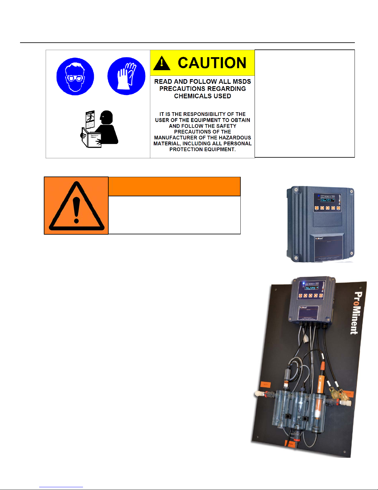
Water disinfection
these chemic als.
DO NOT INSTALL YOUR
WARNING!
2.2 System Mou nting
Fully Assembled System on Acrylic Backpanel
• Locate an area on a flat wall large enough to accommodate the full size of the
18 x 30” acrylic system panel with enough extra r oom to
accommodate flexible sample tubing connections.
• NOTE: Location of the system should not be in the direct
sunlight if mounted outside, as this ma y cause false
temperature readings and can cause tem p eratures insi de the
enclosure t o exceed maximum temperature ratings of 120°F.
• The controller is shipped with a 3 f t. power cord already installed,
for easy con nection to a close indoor wall receptacle.
Alternatively, you may choose, or be required by local electrical
code, to install conduit into the bottom of the controller enclosur e.
Refer to the wiring section of thi s manu al for enclosure opening
sizes and locations.
• Refer to dimensional drawings for location and spa cing of predrilled mounting holes, measure and mar k these locations on the
wall.
• Approximate weight of the assembled system with water flowing,
may be in excess of 30 lbs., so t ake care to choose adequately
sized mount ing hardware.
• NOTE: Spacers on the back of the acrylic panel, if present, are
not secure d and can be easily removed from their groove, if
desired.
control involves
irritating, corrosive,
caustic, and potentially
toxic chemicals. Use
extreme caution and
comply with all nat iona l,
state and lo cal
regulations and
recommendat ions for the
handling and storage of
CONTROLLE R I N ARE AS
ACCESSIBLE TO THE PUBLIC
Page 8
DCM 2 Installation
Individual C omponents
DCM2 Control ler Enclosure M ounting
• Locate an area on a vertical wall where the controller can me mounted at approximately eye level and
have enough clearance to allow the DGMa modular sensor housing to be installed near an d below the
controller. Avoid outdoor installations, especially in direct sunlight. The location of the DGMa sensor
housing must have about 18” of clearance above it to all ow removal of the sens ors, and about 12
inches below to access water sample petcock and a sampl e cup.
NOTE: a common mistake made at installation, is not allowing enough space above the sensor housing
to accommodate routine sensor maintenance.
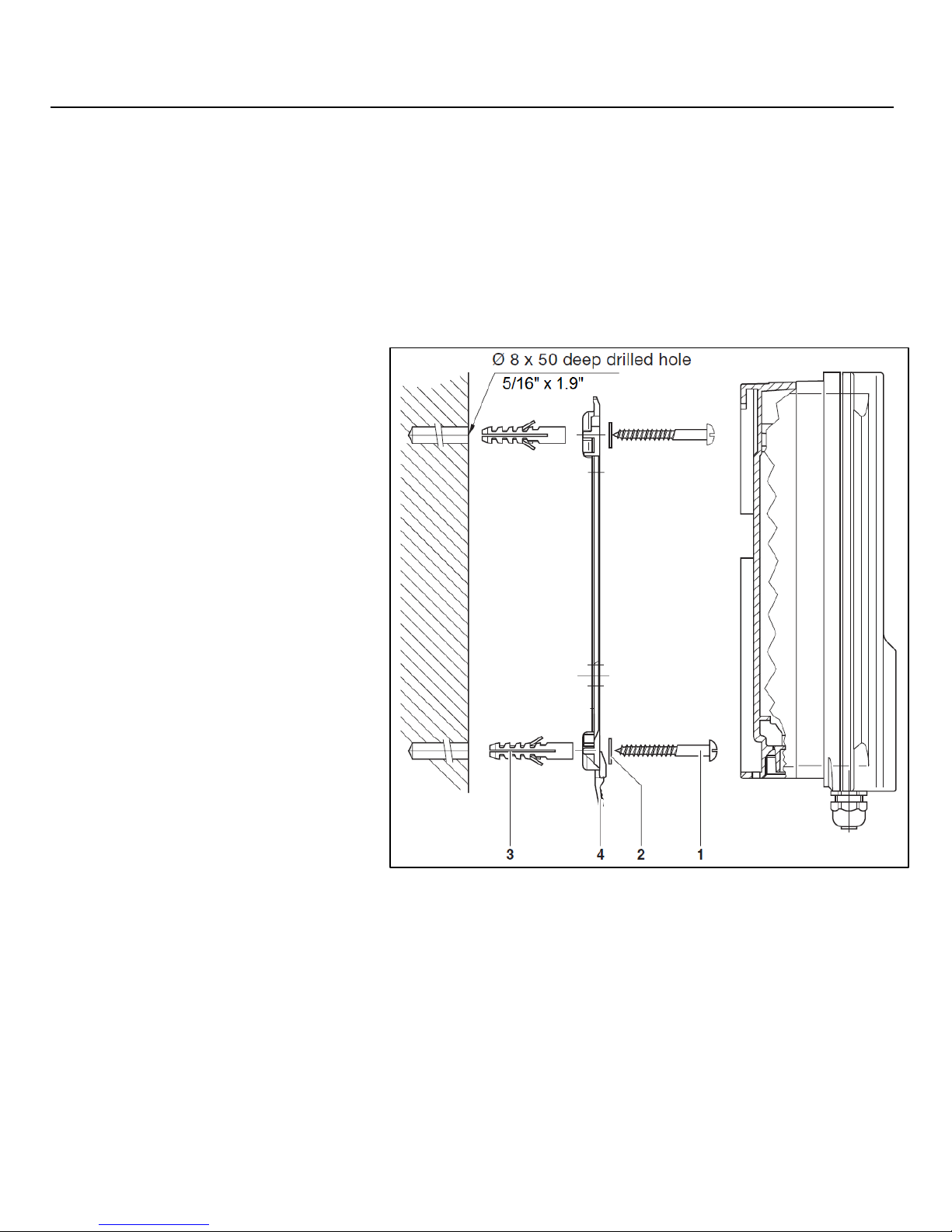
• Individual DCM2 controllers
are shipped with mounting
bracket (4) and mounting
screws (1) to assist with wall
mount installation.
• Disconnect the bracket from
the back of the enclosure by
pressing the black plastic
release clip (4) at the
bottom, and slide the
enclosure down towards t he
clip, then tip the bracket off
the back of the enclosure.
The wall mounting bracket
can then b e used as a
drilling template as shown.
• Mount the bracket on a
vertical wall at approximately
eye level, within 30 in. of the
nearest 120VAC pow er
outlet. Alternativel y, mount
near a power disconnect,
and wir e the power directly
to the controller through
electrical conduit. Conduit
adaptor fittings are available
from ProMinent. Refer to local and national electrical codes for wet locations.
• Fasten enclosure securely to the bracket as shown, by hanging enclosure on the bracket, pushing
the encl osure against wall and lifting until the enclosure snaps securely to the bracket.
• After controller is mounted, time is best used mounting the DGMa mo dular sensor housing to
allow sens ors to equilibrate whil e the r em ainder of the installation, wiring and configuration is
performed.
Page 9
DCM 2 Installation
2.2.1. Sample Connections
Modular Sens or Housing (DGM a)
• When shipped separatel y, the DGMa Sensor housing is mounted to a small white acrylic
backpanel.
• Mount pl ate within 60” of the DCM2 controller, and allow at least 18” clearance above the t op of
the mounting plate. Do not mount in direct sunlight as this will pr omote algae growth and create
temperature swings not representative of the pool or spa under control.
• Using the typical installation drawings on the following pages, connect sampl e tubing to the DGMa
modular sen sor housing a nd the main recirculation lines, using the fittings supplied.
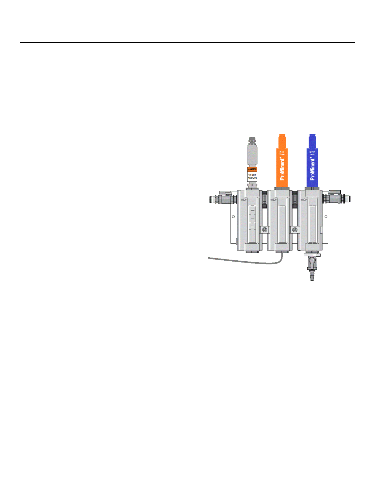
NOTE: The default mounting of the modular
housing is to flow from left to right (note the flow
direction molded into each module).
• If preferred, the modular housing is
reversible by removing t he assembled
modules fr om the black upper snap cli ps.
• First disconnect the spa cer standoff
brackets a nd pull the module assembly to
unsnap it from the upper clips.
• Once it is loose, simply flip the assembled
modules so t hat the molded arr ows on the
modules are pointing right to left,
• Then reconnect it to the standoff brackets
and remount onto the backpanel.
Adjustment of the standof f brackets
mounting screws may be needed.
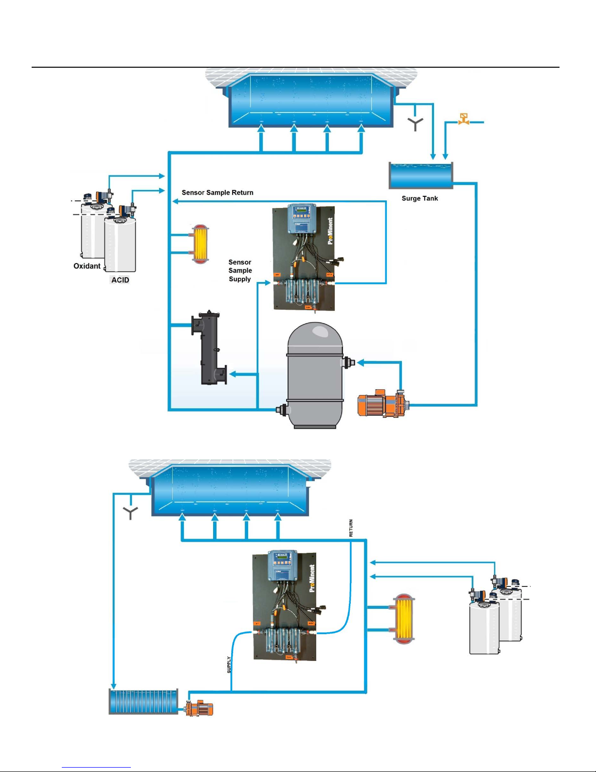
• Next, use the typical installation drawing
below as a guide, and connect the sample
supply and return tubi ng using the selection
of fittings supplied.
NOTE: Keep in mi nd that a very smal l sample volume (11-12 GPH) is needed for ProMinent
controllers. That is only (0.18 GPM) com pared to other aquatic controllers requiring 1-3 GPM .
Sensor sample should always be taken from downstream of the filter, but up stream of UV or
Ozone treatment system, heater and any chemical inj ection. Discharge sample into the line
returning t o the pool or spa as close to the pool as pos sible to get the maximum pressure
differential. Using the pressure drop created by other devices like heaters or the UV system works
best.
CAUTIO N: Never take the senso r sample from u nfiltered water as this may introduce hair or o t her debris into t he
flow switch and sample cell. Never return sample to the suction side of the recirculatio n pump as this will cause a
negative p ressure enviro nment (vacuum) for the sensors, which will cause non-warranty dam age to the sensors,
and more importantly, w i ll cause erroneous readings and poor water quality control.
Page 10
DCM 2 Installation
Proper Vacuum Filter Arrangement
Proper Pressure Filter Arrangem ent
Page 11
DCM 2 Installation
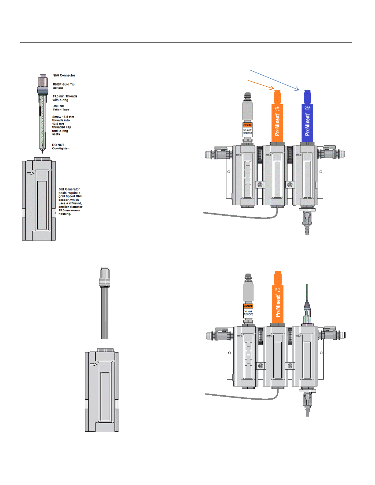
ORP sensor
Permanently
DCM200 Sensor Arrangement
DCM2-Cl Sensor Arrangement
CLB3 Sensor
2.2.2. Sensor Installation
pH sensor
connected cable
CLB3 Free
Chlorine sensor
Unique 13.5 mm
Swivel cap with
o-ring
USE NO Teflon
tape
Screw 13.5 mm
threads into
threaded cap
until o-ring
seats. Hand
tight should be
enough
DO NOT over
tighten
DCM2-Cl
versions of the
controll er are
supplied with a
CLB3 free
chlorine sensor,
instead of an
ORP sensor. The
CLb3 sensor
also uses the
13.5mm cell.
Page 12
 Loading...