

Page 1
ProMinent
®
Betriebsanleitung
Operating Instructions
Mode d’emploi
Instrucciones de servicio
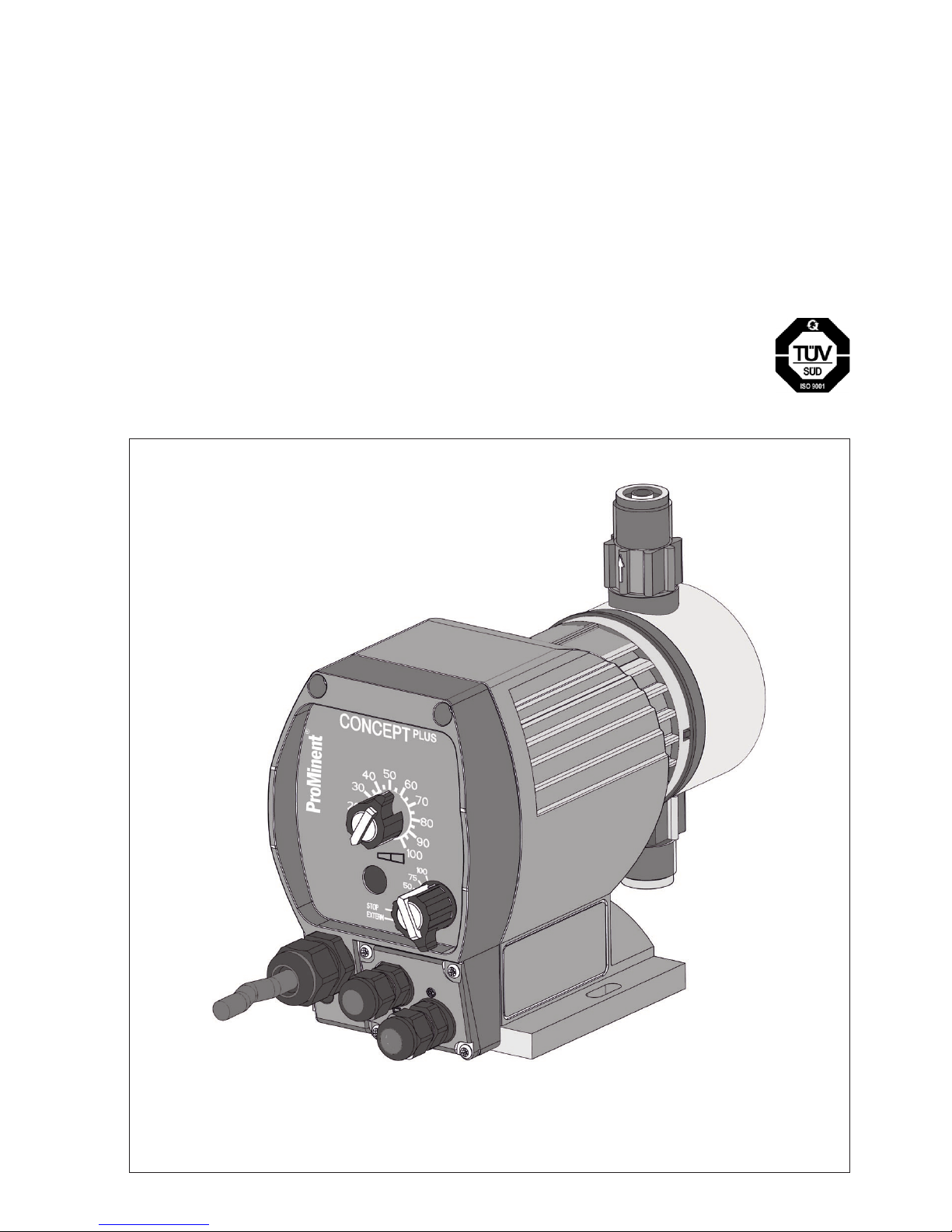
ProMinent® CONCEPT
PLUS
Part No. 987033 ProMinent Dosiertechnik GmbH · 69123 Heidelberg · Germany BA CO 015 02/05 G/GB/F/E
Page 2

2
ProMinent
®
Betriebsanleitung in Deutsch von Seite 3 bis 13
Operating Instructions in English from page 15 to page 25
Mode d’emploi en francais de la page 27 à la page 37
Instrucciones de servicio en español de página 39 hasta página 49
D
GB
F
E
Page 3

15
ProMinent
®
Please read the opertaing instructions through completely before
commissioning this equipment!
Do not discard!
Any part which has been subject to misuse is excluded from the
warranty!
Page
General user instructions 16
1 Equipment overview .................................................................. 17
2 Type overview/material details ................................................. 18
3 Safety........................................................................................... 18
4 Storage and transport ............................................................... 19
5 Assembly and installation ......................................................... 19
6 Commissioning .......................................................................... 20
7 Maintenance
...............................................................................
20
8 Repair
..........................................................................................
21
9 Troubleshooting ......................................................................... 21
10 Decommissioning and disposal ............................................... 22
11 Technical data ............................................................................ 22
12 Accessories ................................................................................ 23
Declaration of Conformity 25
Table of Contents
Page 4
16
ProMinent
®
General user instructions
Please read through the following user instructions carefully! They will
help you get the best use out of the operating instruction manual.
The following are highlighted in the text:
• Enumerated points
Instructions
Safety guidelines:
WARNING
Describes a potentialy dangerous situation. If not avoided, could
cause fatal or serous injury.
IMPORTANT
Describes a potentialy dangerous situation. If not avoided, could
cause damage to property.
This operating instructions manual is aimed at experts in metering
pumps and their operation.
If you require detailed installation instructions please order ”General Operating Instructions Manual, ProMinent
®
Solenoid Metering
Pumps” (Order No. 987057).
General user instructions
▲
Page 5

17
ProMinent
®
Equipment overview
1 Equipment overview
1 Stroke length adjustment knob
2 Error/operating indicator (error - red / operation - green)
3 Multifunction switch (stroke rates (in % of 180 strokes/min), stop,
operating mode ”external” (Retrofit kit))
4 Power cable
5 “External actuation” socket (actuation via contact signal in ”external”
operating mode; Retrofit kit)
6 “Float switch” socket (for 1-stage float switch; Retrofit kit)
7 Suction valve
8 Discharge valve
The leakage bore is between the suction valve and the drive housing.
7
4
6
8
5
2
1
3
Page 6

18
ProMinent
®
2 Type overview/material details
Order No. CONCEPT
PLUS
, CNPa, 115 V versions
Pump type liquid end material
PP (with EPDM*) NP** (with Viton
®
*)
1000 1022480 1022484
1601 1022481 1022485
1002 1022482 1022486
0704 1022483 1022487
Order No. CONCEPT
PLUS
, CNPa, 230 V versions
Pump type liquid end material
PP (with EPDM*) NP** (with Viton
®
*)
1000 1022452 1022476
1601 1022453 1022477
1002 1022474 1022478
0704 1022475 1022479
* Seal material
** Valve body material is PVC
The valve balls are made of ceramics.
3 Safety
• The pump may be used only for metering liquid media!
• All other uses or modifications are prohibited!
• The pump is not suitable for metering gaseous media or solids!
• The pump must be operated by appropriately trained and authorised
personnel!
The personnel must be familiar with metering pumps and their operation!
WARNING
• The pump may start to operate as soon as it connected to the mains
power supply!
Ensure that no hazardous metering chemical can leak out!
If you have not done so, set the multifunction switch to STOP or
disconnect the pump from the mains immediately.
• The pump cannot be switched off! In the case of an electrical failure,
disconnect the mains cable from the power supply.
• Disconnect the power cable from the mains before working on
the pump.
Type overview/material details / Safety
Correct use of
equipment
Page 7

19
ProMinent
®
Safety / Storage and transport / Assembly and installation
• Risk of electric shock - This pump is supplied with a grounding
conductor and grounding-type attachment plug. To reduce the risk of
electric shock, be certain that it is connected only to a properly
grounding-type receptacle.
• Always depressurise liquid end before working on the pump.
• Always empty and rinse the liquid end before working on the pump
if used with hazardous or unknown feed chemicals.
• Wear safety equipment appropriate to the metering chemical when
working on the liquid end.
• Never let the pump work against a significantly increased operat
ing pressure or a closed stop tap on the discharge-side. This can
cause lines to burst.
• Avoid overfeed due to positive pressure difference between in take
and discharge sides. E.g. use a ball check valve with at least 1.5
bar opening pressure with an atmospheric pressure outlet (not 0213).
• Assembly and installation of ProMinent
®
metering pumps with nonoriginal parts, which have not been checked and recommended by
ProMinent is not allowed and can lead to harm to persons or
property for which no liability can be accepted.
• Note all national directives which apply to the installation.
The sound pressure level is < 70 dB (A) at a distance of 1 m in accordance
with EN 23741 or EN 23742 at maximum stroke, maximum stroke rate, maximum back pressure (water)
4 Storage and transport
Ambient conditions for storage and transport:
Storage and transport temperature: -10 to +50 °C
Humidity: < 92 % rel. humidity,
non-condensing
5 Assembly and installation
IMPORTANT
• The pump must not vibrate when installed.
• Solenoid metering pumps tend to overfeed if the back pressure
is too low. In this case fit a ball check valve, a multifunction valve
or a discharge valve with 1.5 bar opening pressure downstream
from the pump (not 0213).
Sound pressure level
Page 8

20
ProMinent
®
Assembly and installation / Commissioning / Maintenance
• Use only original hoses with the specified diameter and wall
thickness! It is not otherwise possible to ensure the durability of
the connection to the pump valves!
• For tips on hydraulic installation, order the ”General Operating
Instructions Manual, ProMinent
®
Solenoid Metering Pumps”
(Order No. 987057).
• Check that the mains power supply and frequency match the
values specified on the rating plate!
• Note all national directives which apply to the installation!
Mount metering pump on a tank or bracket using screws and
washers (Ø 6 mm).
Keep suction height and length of suction hose as short as possible.
Install suction hose in an ascending position.
Cut the suction and pressure pipe to the required length.
Push union nut and clamping ring onto the hose.
Push the cut hose onto the grommet up to the stop.
Press on hose and tighten the union nut.
Mount the foot-actuated valve.
For this purpose, cut the free suction hose end such that the footactuated valve is suspended close above the tank bottom.
In case of metering solutions with contaminations or residues, cut
the free suction hose end such that the foot-actuated valve is
suspended at least 50 mm above the tank bottom.
6 Commissioning
Precision metering is possible only within a stroke length range of
30-100 %.
7 Maintenance
Quarterly at normal load (approx. 30 % continuous operation)
Check the pump diaphragm for damage
Check that the discharge and suction valves and the discharge lines
are seated firmly
Check the overall tightness of the liquid end (in particular leakage
opening between suction value and drive housing)
Check liquid end screws are tight
Tightening torque for liquid end screws: 4.5 to 5 Nm
▲▲▲
(section)
Hose
Union nut
clamping
ring
grommet
O-Ring
intake
connector
▲
▲▲▲ ▲ ▲▲
▲
Service interval
▲
Page 9

21
ProMinent
®
Repair / Troubleshooting
8 Repair
Repairs which may be carried out by qualified persons (according to
safety instructions):
• Cleaning a valve
• Replacing the diaphragm (installation instructions included with
replacement diaphragm)
For all other repairs consult your ProMinent® Subsidiary.
9 Troubleshooting
The pump does not prime despite full stroke action and venting
Cause: Crystalline deposits on the ball seat due to valves drying out.
Remedy: Remove suction hose from the supply tank and rise liquid
end thoroughly.
If unsuccessful, dismantle valves and clean.
Fluid is leaking from the head washer
Cause: The liquid end is leaking at the pump diaphragm.
Remedy: Screw in the liquid end anti-clockwise (torque: 4.5 to 5 Nm)
If unsuccessful, replace the diaphragm (installation instructions
included with the diaphragm).
Error/operating indicator not lit
Cause: No or incorrect mains voltage.
Remedy: Use mains voltage as specified on the rating plate.
Error/operating indicator lit red
Cause: Liquid level in the supply tank has reached “low liquid level”.
Remedy: Top up supply tank.
Cause: Electronic failure.
Remedy: Send pump away for repair.
Page 10

22
ProMinent
®
* Suction lift with filled suction line and liquid end
** Priming lifts with clean and wetted valves, metering fluid, water
(20 °C), at 100 % stroke length, 180 strokes/min, atmospheric
pressure outlet and/or open venting valve and correctly installed lines.
Materials
Liquid end material specification: see type code
Housing: PPE, glass fibre reinforced
Electrical data
Mains frequency: 50 Hz / 60 Hz
* Fuses must have approvals according to VDE, UL and CSA.
Decommissioning and disposal / Technical data
10 Decommissioning and disposal
IMPORTANT
• When decommissioning a pump, clean all traces of chemicals
and dirt from the housing and particularly the liquid end.
• Observe all relevant disposal directives for your area
(particularly with regard to electronic waste)
11 Technical data
Performance table 230 V version
115 V/AC version CNPa
Wattage: 11 W
Current I eff: 0.26 A
Peak current 1.2 A
Switch-on peak current < 3 A for < 0.1 ms
Fuse*: 0.315 AT
230 V/AC version CNPa
Wattage: 10 W
Current I eff: 0.12 A
Peak current 0.5 A
Switch-on peak current < 4 A for < 0.1 ms
Fuse*: 0.16 AT
10
16
10
7
0.6
1.0
2.0
3.9
0.07
0.10
0.18
0.39
5
8
5
3.5
0.8
1.4
2.6
4.5
0,08
0.13
0.24
0.42
180
180
180
180
6x4
6x4
6x4
6x4
6
6
5
4
1.8
2.0
2.5
3.0
8
8
5.5
3
1000
1601
1002
0704
Pump
type
Minimum delivery rate
at maximum
back pressure
Minimum feed rate
at medium
back pressure
Max.
stroke
rate
Connection
size
ext. Ø x int. Ø
Priming
lift
*
Priming
lift
**
Admissible
priming pressure
Intake
bar l/h
ml/
stroke
bar l/h
strokes/
min mm m Wc m Wc bar
ml/
stroke
3
1.5
8.0
13.5
0.74
1.42
1.5
1.0
10.8
15.5
1.00
1.4
180
180
8x5
8x5
2
1.5
2.0
1.5
1
0.5
0308
0213
Page 11

23
ProMinent
®
Technical data / Accessories
Temperature details
Storage and transport temperature: -10 °C...+50 °C
Function at ambient temperature: -10 °C...+45 °C
Admissible feed chemical temperature: -10 °C...+35 °C
NP
Material
feed unit
Long term at max. back
pressure
max. 15 min.
at max. 2 bar
PP
50 °C
45 °C
100 °C
60 °C
Climate
Admissible relative air humidity: 92 %, non condensing.
Load in wet and alternating climate: FW 24 in accordance with DIN 50016.
Enclosure rating and safety class
Contact and moisture protection: IP 65 in accordance with IEC 529,
EN 60529, DIN VDE 0470 Part 1 Safety class 1 - electric mains with earth
Sound pressure level
Sound pressure level: < 70 dB(A) at a distance of 1 m in accordance
with EN 23741 or EN 23742 at maximum stoke, maximum stroke rate,
maximum back pressure (water)
Shipping weight
Shipping weight: 1.8 kg
12 Accessories
Suction lance for 200 l drum, tank opening 2“ DIN 570, PPE 1022511
Suction lance for 200 l drum, tank opening 2“ DIN 570, PCB 1022512
Suction lance for tank 5-50 l drum, tank opening d50, PPE 1022645
Suction lance for tank 5-50 l drum, tank opening d50, PCB 1022644
Adjustable suction lance with single-stage level switch, closing in the
event of lack of chemicals.
The delivery scope also includes the parts required for connecting the
pump.
Retrofit kit External + level CNP 1022099
Retrofit kit level switch CNP* 1022115
*connecting parts given suction lances and tanks provided by the
customer
Suction lances
Retrofit kits
Page 12

24
ProMinent
®
Technical data
CONCEPT
PLUS
(dimensions in mm)
M20 x1.5
33.9
76
10.5
56.1
105.3
85
158.7
132.5
84.7
18.3
80
92.5
6
70 (90*)
140 (156*)
98 (110*)
* dimensions for pump type 0308, 0213
Page 13

25
ProMinent
®
Conformity declaration
 Loading...