

ProMinent alpha ALPc 1001, alpha ALPc 1002, alpha ALPc 1007, alpha ALPc 0707, alpha ALPc 1004 Operating Instructions Manual
...Page 1
Motor-driven Metering Pump
alpha ALPc
Operating instructions
EN
Original operating instructions (2006/42/EC)Part no. 986353 BA ALP 015 08/18 EN
Please carefully read these operating instructions before use. · Do not discard.
The operator shall be liable for any damage caused by installation or operating errors.
The latest version of the operating instructions are available on our homepage.
Page 2
Supplementary information
Fig. 1: Please read!
Read the following supplementary information
in its entirety! You will benefit more from using
the operating instructions should you already
know this information.
The following are highlighted separately in the
document:
n Enumerated lists
Instructions
ð
Outcome of the instructions
Ä ‘State the identity code and serial number’
on page 2
: Links to points in this chapter
- refer to ... : References to points in this docu‐
ment or another document
[Keys]
Information
This provides important information
relating to the correct operation of the
unit or is intended to make your work
easier.
Safety Information
Safety information is identified by pictograms see Safety Chapter.
Validity
These operating instructions conform to current
EU regulations applicable at the time of publi‐
cation.
State the identity code and serial number
Please state identity code and serial number,
which you can find on the nameplate when you
contact us or order spare parts. This enables
us to clearly identify the unit type and material
versions.
Supplemental directives
2
Page 3

Table of contents
1 Identity code............................................................................................................................ 5
2 Safety chapter......................................................................................................................... 7
3 Storage, Transport and Unpacking....................................................................................... 12
4 Overview of equipment......................................................................................................... 13
5 Functional description........................................................................................................... 14
5.1 Power end.................................................................................................................... 14
5.2 Liquid End.................................................................................................................... 14
6 Assembly............................................................................................................................... 15
7
Installation, hydraulic............................................................................................................. 16
7.1 Installing hose lines...................................................................................................... 17
7.1.1 Installation of the suction and discharge line............................................................ 17
7.1.2 Installation of metering pumps with bleed valve........................................................ 20
7.1.3 Basic installation notes.............................................................................................. 20
8 Electrical installation.............................................................................................................. 23
9 Start up.................................................................................................................................. 24
10 Maintenance.......................................................................................................................... 28
11 Repairs.................................................................................................................................. 31
11.1 Cleaning valves.......................................................................................................... 31
11.2 Replacing the diaphragm........................................................................................... 32
11.3 Replacing the complete dosing head......................................................................... 36
12 Troubleshooting.................................................................................................................... 37
12.1 Faults and troubleshooting......................................................................................... 38
12.2 All other faults............................................................................................................. 39
13 Decommissioning and disposal............................................................................................. 40
13.1 Decommissioning....................................................................................................... 40
13.2 Disposal...................................................................................................................... 41
14 Technical data....................................................................................................................... 42
15 Design Documents................................................................................................................ 46
16 Dimensional drawings........................................................................................................... 47
17 Further order information ..................................................................................................... 48
Table of contents
3
Page 4

18 Declaration of Conformity for Machinery............................................................................... 49
Table of contents
4
Page 5

1 Identity code
alpha product range, version c
ALPc Type Capacity
bar l/h (at 50 Hz)
1001 10 0.9
1002 10 1.8
1004 10 3.5
1008 10 7.7
0707 7 6.9
0417 4 17.0
0230 2 29.7
Dosing head material
PPE PP/PP/EPDM
PPB PP/PP/FPM-B
NPE Clear acrylic/PVC//EPDM
NPB Clear acrylic/PVC/FPM
PVT PVDF/PVDF/PTFE
Seal material
2 Without valve spring, with bleed valve
3 with 2 valve springs (approx. 0.1 bar, material 1.4571), with bleed valve
Hydraulic connector
0 Standard connection in line with technical data
Design
0 with ProMinent logo
M modified
Electrical connection
Identity code
5
Page 6

alpha product range, version c
A 230 V , 50/60 Hz, 2 m European
B 230 V, 50/60 Hz, 2 m Swiss
C 230 V, 50/60 Hz, 2 m Australian
D 115 V , 50/60 Hz, 2 m USA
Accessories
0 no accessories
1 with foot and injection valve, 2 m PVC suction line, 5 m
metering line
Identity code
6
Page 7

2 Safety chapter
Identification of safety notes
The following signal words are used in these
operating instructions to denote different severi‐
ties of danger:
Signal word Meaning
WARNING Denotes a possibly
dangerous situation.
If this is disregarded,
you are in a lifethreatening situation
and this can result in
serious injuries.
CAUTION Denotes a possibly
dangerous situation.
If this is disregarded,
it could result in slight
or minor injuries or
material damage.
Warning signs denoting different types of
danger
The following warning signs are used in these
operating instructions to denote different types
of danger:
Warning signs Type of danger
Warning – automatic
start-up.
Warning – hand inju‐
ries.
Warning – highvoltage.
Warning signs Type of danger
Warning – danger
zone.
Intended use
n Only use the pump to meter liquid feed
chemicals.
n Only use the pump after it has been cor‐
rectly installed and started up in accord‐
ance with the technical data and specifica‐
tions contained in the operating
instructions.
n Observe the general limitations with regard
to viscosity limits, chemical resistance and
density - see also ProMinent® Resistance
List in the Product Catalogue or at
www.prominent.com!
n All other uses or modifications are pro‐
hibited.
n The pump is not intended for the metering
of gaseous media and solids.
n The pump is not intended to meter flam‐
mable media.
n The pump is not intended for the metering
of explosive media.
n The pump is not intended for operation in
areas at risk from explosion.
n The pump is not intended for exterior
applications without the implementation of
suitable protective measures.
n The pump should only be operated by
trained and authorised personnel, see the
following "Qualifications" table.
n You have a responsibility to adhere to the
information contained in the operating
instructions at the different phases of the
unit's service life.
Safety chapter
7
Page 8

Qualification of personnel
Action Qualification
Storage, transport,
unpacking
Instructed person
Assembly Technical personnel,
service
Planning hydraulic
installation
Qualified personnel
who have a thorough
knowledge of
metering pumps.
Hydraulic installation Technical personnel,
service
Installation, electrical Electrical technician
Operation Instructed person
Maintenance, repair Technical personnel,
service
Decommissioning,
disposal
Technical personnel,
service
Troubleshooting Technical personnel,
electrical technician,
instructed person,
service
Explanation of the terms:
Technical personnel
A qualified employee is deemed to be a person
who is able to assess the tasks assigned to him
and recognise possible dangers based on
his/her technical training, knowledge and expe‐
rience, as well as knowledge of pertinent regu‐
lations.
Note:
A qualification of equal validity to a technical
qualification can also be gained by several
years employment in the relevant work area.
Electrical technician
Electrical technicians are deemed to be people,
who are able to complete work on electrical
systems and recognise and avoid possible dan‐
gers independently based on their technical
training and experience, as well as knowledge
of pertinent standards and regulations.
Electrical technicians should be specifically
trained for the working environment in which
they are employed and know the relevant
standards and regulations.
Electrical technicians must comply with the pro‐
visions of the applicable statutory directives on
accident prevention.
Instructed person
An instructed person is deemed to be a person
who has been instructed and, if required,
trained in the tasks assigned to him/her and
possible dangers that could result from
improper behaviour, as well as having been
instructed in the required protective equipment
and protective measures.
Service
Customer Service department refers to service
technicians, who have received proven training
and have been authorised by ProMinent or Pro‐
Maqua to work on the system.
Safety chapter
8
Page 9

Safety information
WARNING!
Warning about personal and material
damage
The pump can start to pump, as soon
as it is connected to the mains voltage.
– Install an emergency cut-off switch
in the pump power supply line or
integrate the pump in the emer‐
gency cut-off management of the
system.
WARNING!
Danger of electric shock
A mains voltage may exist inside the
pump housing.
– If the pump housing has been
damaged, you must disconnect it
from the mains immediately. It
may only be returned to service
after an authorised repair.
WARNING!
Warning of hazardous feed chemical
Should a dangerous feed chemical be
used: it may escape from the hydraulic
components when working on the
pump, material failure or incorrect han‐
dling of the pump.
– Take appropriate protective meas‐
ures before working on the pump
(e.g. safety glasses, safety
gloves, ...). Adhere to the material
safety data sheet for the feed
chemical.
–
Drain and flush the liquid end
before working on the pump.
WARNING!
Danger from hazardous substances!
Possible consequence: Fatal or very
serious injuries.
Please ensure when handling haz‐
ardous substances that you have read
the latest safety data sheets provided
by the manufacture of the hazardous
substance. The actions required are
described in the safety data sheet.
Check the safety data sheet regularly
and replace, if necessary, as the
hazard potential of a substance can be
re-evaluated at any time based on new
findings.
The system operator is responsible for
ensuring that these safety data sheets
are available and that they are kept up
to date, as well as for producing an
associated hazard assessment for the
workstations affected.
Safety chapter
9
Page 10

CAUTION!
Warning of feed chemical spraying
around
Feed chemical can spray out of the
hydraulic components if they are
manipulated or opened due to pressure
in the liquid end and adjacent parts of
the system.
– Disconnect the pump from the
mains power supply and ensure
that it cannot be switched on again
by unauthorised persons.
–
Depressurise the system before
commencing any work on
hydraulic parts.
CAUTION!
Warning of feed chemical spraying
around
An unsuitable feed chemical can
damage the parts of the pump that
come into contact with the chemical.
– Take into account the resistance
of the wetted materials and the
ProMinent Resistance List when
selecting the feed chemical - see
the ProMinent Product Catalogue
or visit ProMinent.
CAUTION!
Warning of feed chemical spraying
around
The metering pump can generate a
multiple of its rated pressure. Hydraulic
parts can rupture if a discharge line is
blocked.
– Correctly install a relief valve in the
discharge line downstream of the
metering pump.
CAUTION!
Danger of personnel injury and material
damage
The use of untested third party parts
can result in personnel injuries and
material damage.
– Only fit parts to metering pumps,
which have been tested and rec‐
ommended by ProMinent.
CAUTION!
Danger from incorrectly operated or
inadequately maintained pumps
Danger can arise from a poorly acces‐
sible pump due to incorrect operation
and poor maintenance.
– Ensure that the pump is acces‐
sible at all times.
–
Adhere to the maintenance inter‐
vals.
Safety chapter
10
Page 11

CAUTION!
Warning against illegal operation
Observe the regulations that apply
where the device is installed.
Fixed separating protective equipment
n Cover
n Dosing head
n Housing
The customer may only remove the cover to
adjust the stroke length.
Customer should only remove the dosing head
in accordance with the "Repair" chapter.
Only the ProMinent Service department are
authorised to remove the housing.
Ensure that all protective equipment is properly
fitted before the pump is operated.
Other safety equipment
Vor Deckelabnahme
Pumpe abschalten
Switch off pump
before opening
Arrêtez la pompe
avant de l‘ouvrir
P_ALP_0010_SW
Fig. 2
Ensure that the warning label is always fitted
and legible.
Circuit breaker
The driver motor is fitted with a circuit breaker,
which automatically switches off the motor
when it overheats to more than 106 °C.
The circuit breaker switches the pump on again
once the motor has cooled down.
Information in the event of an emergency
In an emergency, either pull out the mains plug
or press the emergency-off switch, installed by
the customer, or disconnect the pump in line
with the emergency-shut-down guidelines for
your system!
If feed chemical escapes, also ensure that the
pump's hydraulic environment is at atmospheric
pressure. Adhere to the material safety data
sheet for the feed chemical.
Sound pressure level
Sound pressure level LpA < 70 dB according to
EN ISO 20361
at maximum stroke length, maximum stroke
rate, maximum back pressure (water)
Safety chapter
11
Page 12

3 Storage, Transport and Unpacking
Safety Information
WARNING!
Only return metering pumps for repair
in a cleaned state and with a flushed
liquid end - refer to "Decommissioning!
Only return metering pumps with a
completed Decontamination Declara‐
tion form. The Decontamination Decla‐
ration constitutes an integral part of an
inspection / repair order. A unit can only
be inspected or repaired when a Decla‐
ration of Decontamination Form is sub‐
mitted that has been completed cor‐
rectly and in full by an authorised and
qualified person on behalf of the pump
operator.
The "Decontamination Declaration
Form" can be found on our homepage.
CAUTION!
Danger of material damage
The device can be damaged by incor‐
rect or improper storage or transporta‐
tion!
– The unit should only be stored or
transported in a well packaged
state - preferably in its original
packaging.
–
The packaged unit should also
only be stored or transported in
accordance with the stipulated
storage conditions.
– The packaged unit should be pro‐
tected from moisture and the
ingress of chemicals.
Ambient conditions
Ambient conditions - refer to "Technical Data"
chapter.
Scope of delivery
Compare the delivery note with the scope of
delivery:
n Metering pump with mains cable
n Connector kit for hose/pipe connection
n Product-specific operating instructions with
Declaration of Conformity
Storage, Transport and Unpacking
12
Page 13
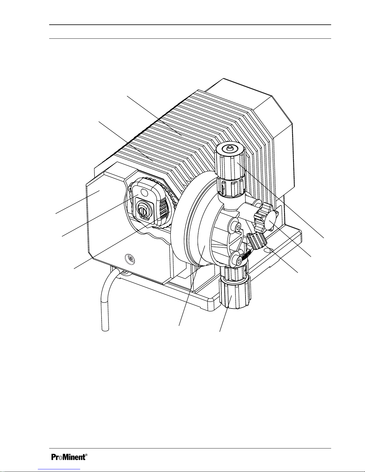
4 Overview of equipment
1
2
3
10
9
8
7
6
5
4
P_ALP_0007_SW
Fig. 3
1 Cover
2 Motor mounting
3 Housing
4 Pressure connector
5 Bleed valve
6 Bypass hose nozzle
7 Suction connector
8 Dosing head
9 Eccentric disc with scale
10 Latched slide
Overview of equipment
13
Page 14

5 Functional description
5.1 Power end
The cam for the stroke movement is guided in
an eccentric disc. Pumps of this size do not
therefore require conventional return springs –
the suction and pressure stroke are positively
driven.
The stroke length can be adjusted by a latched
slide (9) from 100% to 0 in increments of 10%.
The diaphragm is always deflected from the
neutral centre position, producing a smooth
sinusoidal stroke motion.
5.2
Liquid End
The dosing process is performed as follows:
The diaphragm is pressed into the dosing head;
the pressure in the dosing head closes the suc‐
tion valve and the feed chemical flows through
the discharge valve out of the dosing head. The
diaphragm is now drawn out of the dosing
head; the discharge valve closes due to the
negative pressure in the dosing head and fresh
feed chemical flows through the suction valve
into the dosing head. One cycle is completed.
Functional description
14
Page 15

6 Assembly
WARNING!
The IP 23 protection against moisture
and accidental contact only applies to
horizontal pump bases with vertically
installed pumps.
CAUTION!
When assembling the pump, ensure
that there is sufficient room around the
pump for operation, maintenance,
repairs and quick disconnection of the
mains plug.
Capacity too low
Vibrations can disturb the liquid end
valves.
–
Secure the metering pump to
ensure that no vibrations can
occur.
Capacity too low
If the liquid end valves are not upright,
they cannot close correctly.
–
Ensure that the discharge valve is
upright.
Assemble the metering pump on a
storage tank or a bracket using screws
and U-washers (Ø 5 mm).
Assembly
15
Page 16

7 Installation, hydraulic
Safety notes
CAUTION!
Warning of feed chemical spraying
around
An unsuitable feed chemical can
damage the parts of the pump con‐
tacted by the chemical.
– Take into account the resistance
of the materials which will come
into contact with the chemical
when selecting the feed chemical see the ProMinent Product Cata‐
logue or visit www.prominent.com.
CAUTION!
Warning of feed chemical spraying
around
Pumps which are not fully installed
hydraulically can pump feed chemical
from the outlet opening of the discharge
valve as soon as they are connected to
the mains power supply.
– First install the pump hydraulically,
then electrically.
–
In the event that you have failed to
do so, press the On/Off switch (on
site) or the Emergency Stop
switch.
CAUTION!
Warning of feed chemical spraying
around
Feed chemical can spray out of the
hydraulic components if they are
manipulated or opened due to pressure
in the liquid end and adjacent parts of
the system.
– Disconnect the pump from the
mains power supply and ensure
that it cannot be switched on again
by unauthorised persons.
–
Depressurise the system before
commencing any work on
hydraulic parts.
CAUTION!
Danger from rupturing hydraulic com‐
ponents
Peak loads during the dosing stroke
can cause the maximum permissible
operating pressure of the system and
pump to be exceeded.
– The discharge lines are to be
properly designed.
Installation, hydraulic
16
Page 17

CAUTION!
Danger of personnel injury and material
damage
The use of untested third party parts
can result in personnel injuries and
material damage.
– Only fit parts to metering pumps,
which have been tested and rec‐
ommended by ProMinent.
7.1 Installing hose lines
7.1.1
Installation of the suction and
discharge line
Safety notes
CAUTION!
Warning of feed chemical spraying
around
If the pipes are not installed correctly,
they can come lose or burst.
– Route all hose lines so they are
free from mechanical stresses and
kinks.
–
Only use original hoses with the
specified hose dimensions and
wall thicknesses.
– Only use clamp rings and hose
nozzles that are intended for the
hose diameter in question to
ensure the long service life of the
connections.
CAUTION!
Danger resulting from rupturing
hydraulic components
Hydraulic components can rupture if
the maximum permissible operating
pressure is exceeded.
– Always adhere to the maximum
permissible operating pressure of
all hydraulic components - please
refer to the product-specific oper‐
ating instructions and system doc‐
umentation.
–
Never allow the metering pump to
run against a closed shut-off
device.
– Install a relief valve.
CAUTION!
Hazardous feed chemicals can escape
Hazardous or extremely aggressive
feed chemicals can leak out when
using conventional bleeding procedures
with metering pumps.
– Install a bleed line with return into
the storage tank.
Installation, hydraulic
17
Page 18

CAUTION!
Hazardous feed chemicals can escape
Hazardous or extremely aggressive
feed chemicals can leak out in the
event that the metering pump is
removed from the installation.
– Install a shut-off valve on the
metering pump's pressure and dis‐
charge sides.
CAUTION!
Uncontrolled flow of feed chemical
Feed chemicals can leak through a
stopped metering pump if there is back
pressure.
– Use an injection valve or a
vacuum breaker.
CAUTION!
Uncontrolled flow of feed chemical
Feed chemicals can leak through the
metering pump in an uncontrolled
manner in the event of excessive pri‐
ming pressure.
– Do not exceed the maximum per‐
missible priming pressure for the
metering pump.
Align the pipes so that the metering
pump and the liquid end can be
removed from the side if necessary.
Installation, hydraulic
18
Page 19

Installing hose lines
1. Cut off the ends of the hoses at right
angles.
2. Pull the union nut (20) and clamp ring
(21) over the hose (24) - see figure
Ä ‘Installing hose lines’ on page 18
.
3. Push the hose end (24) up to the stop
over the nozzle (4) and widen, if neces‐
sary.
Ensure that the O-ring and the
flat seal (23) is sitting properly.
Never re-use used PTFE seals.
An installation sealed in this way
is not watertight.
This type of seal is permanently
distorted when subjected to
pressure.
4. Place the hose (24) with the nozzle (22)
onto the valve.
5. Clamp the hose connector: Tighten the
union nut (20) while simultaneously
pressing on the hose (24).
6. Re-tighten the hose connector: Pull on
the hose (24) briefly, which is fastened
to the dosing head and then tighten the
union nut (20) once more.
P_ALP_0009_SW
A
20
21
22
23
24
Fig. 4
A Pressure connector
20 Union nut
21 Clamp ring
22 Nozzle
23 O-ring or flat seal
24 Hose
Installation, hydraulic
19
Page 20

7.1.2 Installation of metering
pumps with bleed valve
Safety notes
CAUTION!
– All the installation and safety notes
for metering pumps without bleed
valves also apply.
Installation of the return line
A return line is additionally connected to the
suction and discharge line.
1. Fasten the tube line to the return hose
nozzle or to the liquid end bleed valve.
PVC hose, soft, 6x4 mm is recom‐
mended.
2. Feed the free end of the return line back
to the storage tank.
3. Shorten the return line so that it does
not dip into the feed chemical in the
storage tank.
7.1.3 Basic installation notes
Safety notes
CAUTION!
Danger from rupturing hydraulic com‐
ponents
Hydraulic components can rupture if
the maximum permissible operating
pressure is exceeded.
– Never allow the metering pump to
run against a closed shut-off
device.
–
With metering pumps without inte‐
gral relief valve Install a relief
valve in the discharge line.
CAUTION!
Hazardous feed chemicals can escape
With hazardous feed chemicals Haz‐
ardous feed chemicals can leak out
when using conventional bleeding pro‐
cedures with metering pumps.
– Install a bleed line with return into
the storage tank.
Shorten the return line so that it cannot
dip into the feed chemical in the storage
tank.
Installation, hydraulic
20
Page 21

P_MAZ_0001_SW
2
1
Fig. 5: Standard installation
1 Main line
2 Storage tank
Installation, hydraulic
21
Page 22

Legend for hydraulic diagram
Symbol Explanation Symbol Explanation
Metering pump Foot valve with mesh
Injection valve Level switch
Multifunctional valve Manometer
Installation, hydraulic
22
Page 23

8 Electrical installation
WARNING!
Danger of an electric shock
Only trained and authorised personnel
may install the pump.
WARNING!
Danger of electric shock
This pump is supplied with a protective
earth conductor and a plug with a pro‐
tective contact.
– Ensure that it is only connected to
a socket with a correctly con‐
nected protective contact to
reduce the risk of electric shock.
WARNING!
Danger of electric shock
In the event of an electrical accident,
quickly disconnect the pump from the
mains power supply.
– Install an emergency cut-off switch
in the pump power supply line or
–
Integrate the pump into the emer‐
gency cut-off guidelines for the
system and inform personnel of
electrical isolating options.
WARNING!
Danger of electric shock
Mains voltage may be present inside
the pump housing.
– If the pump housing has been
damaged, disconnect it from the
mains immediately. Only return the
pump to service after it has been
repaired by authorised personnel.
CAUTION!
If the pump is integrated into a system:
Design the system so that potential
hazardous situations are avoided by
pumps starting up automatically subse‐
quent to unintended power interrup‐
tions.
CAUTION!
There should be a normal possibility of
disconnecting the pump from the mains
power supply to switch it off. Install an
On/Off switch as an option.
Connect the pump to the mains/power
supply using the mains cable.
Electrical installation
23
Page 24

9 Start up
WARNING!
Dangerous reactions are possible due
to contact of feed chemical with water
The feed chemical can mix and react in
the liquid end with water remaining
after testing in the factory.
– Read the safety data sheet on the
feed chemical.
–
Blast the liquid end with com‐
pressed air.
– Flush the liquid end with a suitable
medium through the suction con‐
nector.
WARNING!
Risk of fingers being crushed
– Only adjust the stroke length when
the pump is switched off.
–
Only operate the metering pump
with the cover (1) closed and the
safety screw tightly screwed in.
CAUTION!
Danger with dangerous feed chemicals
Contact with the feed chemical is pos‐
sible provided the following handling
instructions are adhered to.
– If the feed chemical is dangerous,
take appropriate safety precau‐
tions when carrying out the fol‐
lowing handling instructions.
–
Adhere to the feed chemical safety
data sheet.
CAUTION!
Warning of feed chemical spraying
around
An unsuitable feed chemical can
damage the parts of the pump that
come into contact with the chemical.
– Take into account the resistance
of the materials that come into
contact with the medium when
selecting the feed chemical - refer
to the ProMinent®
Resistance List
in the Product Catalogue or at
www.prominent.com.de/
downloads
.
Start up
24
Page 25

–
Reliable metering cannot be guar‐
anteed after the metering pump
has been idle for some time, as
the feed chemical can crystallise in
the valves and on the diaphragm.
Regularly check the valves and
diaphragm.
–
The metering pump should prime
at 100% stroke length, as the pri‐
ming lift depends on the stroke
volume when the liquid end is
empty. If the metering pump has to
prime at a smaller stroke length
and is not priming, reduce the pri‐
ming lift (i.e. briefly lift up the
storage tank with the feed chem‐
ical).
Draining the liquid end
With feed chemicals that should not come into
contact with water.
1. Turn the pump so that the pressure con‐
nector is facing downwards.
2. Allow water to flow out of the liquid end.
3. Flush the suction connector from above
with a suitable medium or blast with
compressed air.
Starting up the metering pump
1.
Fill the liquid end -
Ä ‘Filling the liquid
end’ on page 26
.
2. Check the pump connectors and con‐
nections for leak-tightness.
3. Check the suction valve and discharge
valve for leak-tightness and tighten if
necessary.
4. Check the liquid end for leak-tightness
and tighten the screws on the dosing
head if necessary - see below for
starting torque.
5. Only with bleed valve: Check whether
the bleed valve is closed.
Start up
25
Page 26

Filling the liquid end
With liquid ends without bleed valve:
1. Connect the suction line to the liquid
end but not yet to the discharge line.
2. If fitted: Close the shut-off valve on the
discharge side.
3. Connect a short, transparent section of
hose to the discharge valve.
4. Remove the cover (1) and check
whether the stroke length is set to
100%.
5. If not, set the stroke length to 100% refer to "Adjusting stroke length".
6. Switch on the metering pump and allow
to work at maximum stroke length and
stroke rate until some feed chemical
becomes visible in the short section of
hose.
ð
The liquid end has been filled com‐
pletely without bubbles.
7. Switch off the metering pump.
8. Connect the discharge line to the liquid
end.
Continue as described under "Concluding start
up".
With liquid ends with bleed valve:
1. Connect the suction and discharge line
to the liquid end.
2. Connect the return line.
3. Open the bleed valve by turning the
star-shaped handle in a counter-clock‐
wise direction.
ð
You can now use the return line to
bleed the pump.
4. Remove the cover (1) and check
whether the stroke length is set to
100%.
5. If not, set the stroke length to 100% refer to "Adjusting stroke length".
6. Switch on the metering pump and allow
to work at maximum stroke length and
stroke rate until some feed chemical
becomes visible in the return or dis‐
charge line.
ð
The liquid end has been filled com‐
pletely without bubbles.
7. Switch off the metering pump.
8. Close the bleed valve.
Continue as described under "Concluding start
up".
Concluding start up.
1. Start up the relief valve in the system in
line with its operating instructions.
2. Start up the system.
3. After 24 hours of operation: Tighten the
screws on the dosing head - see below
for tightening torque.
Start up
26
Page 27

Tightening torque
Data Value Unit
Tightening torque for screws: 4.5 ... 5.0 Nm
Adjusting the stroke length
1. Remove the cover (1).
2. Replace the latched slide (9) onto the
eccentric disc.
3. Set the eccentric disc (10) to 100 %.
4. Lock the latched slide in place.
5. Replace the cover (1) and secure with
the safety screw.
A
BB
9
10
1
0
0
8
0
6
0
4
0
2
0
3
0
5
0
7
0
9
0
P_ALP_0008_SW
Fig. 6
Start up
27
Page 28

10 Maintenance
WARNING!
It is mandatory that you read the safety
information and specifications in the
"Storage, Transport and Unpacking"
chapter prior to shipping the pump.
CAUTION!
Warning of feed chemical spraying
around
Feed chemical can spray out of the
hydraulic components if they are
manipulated or opened due to pressure
in the liquid end and adjacent parts of
the system.
– Disconnect the pump from the
mains power supply and ensure
that it cannot be switched on again
by unauthorised persons.
–
Depressurise the system before
commencing any work on
hydraulic parts.
Maintenance
28
Page 29

Standard liquid ends:
Interval Maintenance work Personnel
Quarterly*
n Check the metering diaphragm for damage** - refer to
"Repair".
n Check that the hydraulic lines are fixed firmly to the
liquid end.
n Check that the suction valve and discharge valve are
fitted tightly.
n Check the tightness of the entire liquid end - particularly
around the leakage hole - refer to
Ä ‘Standard liquid
ends:’ on page 29
!
n Check that the flow is correct: Allow the pump to prime
briefly - turn the multifunctional switch briefly to "Test"
n Check that the electrical connections are intact.
n Check the integrity of the housing.
n Check that the dosing head screws are tight.
Technical personnel
* Under normal loading (approx. 30 % of continuous operation)
Under heavy loading (e.g. continuous operation): Shorter intervals.
** Check the diaphragm frequently with feed chemicals that put particular pressure on the dia‐
phragm, e.g. those containing abrasive additives.
P_ALP_0011_SW
Fig. 7: Leakage hole
Maintenance
29
Page 30

Liquid ends with bleed valve:
Interval Maintenance work Personnel
Quarterly* In addition:
n Check that the bypass line is fixed firmly to the liquid
end
n Check that the bleed valve is tight.
n Check the discharge and bypass line for kinks
n Check that the bleed valve is operating correctly.
Technical personnel
* Under normal loading (approx. 30 % of continuous operation)
Under heavy loading (e.g. continuous operation): Shorter intervals.
Tightening torque
Data Value Unit
Tightening torque for screws: 4.5 ... 5.0 Nm
Maintenance
30
Page 31

11 Repairs
Safety notes
WARNING!
Danger of an electric shock
Unauthorised repairs inside the pump
can result in an electric shock.
For this reason repairs inside the pump
should only be carried out by a ProMi‐
nent branch office or representative, in
particular the following:
– Replacement of damaged mains
connection lines
–
Replacement of fuses
WARNING!
It is mandatory that you read the safety
information and specifications in the
"Storage, Transport and Unpacking"
chapter prior to shipping the pump.
WARNING!
Contact with the feed chemical
Parts that come into contact with the
feed chemical are exposed and
touched during repair work.
– Protect yourself against the feed
chemical in case it is hazardous.
Read the safety data sheet on the
feed chemical.
CAUTION!
Warning of feed chemical spraying
around
Feed chemical can spray out of the
hydraulic components if they are
manipulated or opened due to pressure
in the liquid end and adjacent parts of
the system.
– Disconnect the pump from the
mains power supply and ensure
that it cannot be switched on again
by unauthorised persons.
–
Depressurise the system before
commencing any work on
hydraulic parts.
Repairs that may be carried out by qualified
technical personnel, in accordance with the
operating instructions:
n Cleaning valves
n Replacing the diaphragm
All other repairs: Contact the responsible ProM‐
inent branch!
11.1
Cleaning valves
Personnel:
n
Technical personnel
Warning of faulty operation
Refer to the exploded views on the CD
when working on the unit.
Repairs
31
Page 32

11.2 Replacing the diaphragm
n If necessary take protective measures.
n Adhere to the safety data sheet for the
feed chemical.
n Ensure that the system is at atmospheric
pressure.
1. Disconnect the pump from the mains
power supply.
2. Empty the liquid end (turn the liquid end
upside down and allow the feed chem‐
ical to run out; flush out with a suitable
medium; flush the liquid end thoroughly
when using hazardous feed chemicals!)
P_ALP_0012_SW
A
BB
9
10
1
0
0
8
0
6
0
4
0
2
0
3
0
5
0
7
0
9
0
Fig. 8
3. Set the eccentric disc (10) to "0".
The latched slide (9) cannot lock
in this position.
ð
The drive axle is then difficult to
turn.
4. Switch off the pump.
5. Unscrew the hydraulic connectors on
the discharge and suction side.
6. With PP types with bleed valve: Firstly
remove the bleed valve (grip), then lift
off the cover of the liquid end with a
screw driver.
7. Remove the screws (6a).
8. Fully remove the dosing head (6) from
the motor mount (2).
5a
6a
6
P_ALP_0013_SW
Fig. 9
Repairs
32
Page 33

Pump types 1001, 1002, 1004, 1008, 0707,
0417: (Diaphragm WITHOUT holes, threaded
rod without hexagonal nut)
14
16
15
P_ALP_0014_SW
Fig. 10
1. Loosen the diaphragm (15) by turning to
the left - use pliers if necessary.
2. If the threaded rod (16) has come loose
together with the diaphragm, unscrew
the diaphragm from the threaded rod
(turning to the left) - using pliers if nec‐
essary.
3. Screw the threaded rod into the con‐
necting rod thread and use a flat wrench
(SW9) to tighten securely at the width
across flats.
4. Position the backplate (14) on the pump
housing.
5. Screw the diaphragm onto the threaded
rod and tighten manually. Ensure that
the backplate no longer moves from
side to side, although it should still be
able to turn slightly.
6. Place the dosing head (2) with the
screws (1) onto the diaphragm (3) and
the backplate (4) - ensure that the suc‐
tion connector points downwards in the
pump's subsequent fitting position.
7. Gently tighten the screws (6a) and then
tighten cross-wise.
Repairs
33
Page 34

Pump type 0230: (Diaphragm WITH holes,
threaded rod with hexagonal nut)
P_ALP_0015_SW
Fig. 11
1. Use a flat wrench (SW 8) to loosen the
hexagonal nut (arrow) in front of the
connecting rod by about one turn.
2. Loosen the diaphragm (15) with the
backplate (14) and the threaded rod (16)
from the motor mount (2) by turning it to
the left.
14
16
15
P_ALP_0014_SW
Fig. 12
3. Unscrew the threaded rod (16) from the
diaphragm (15) (possibly holding the
threaded rod with pliers and loosening
the diaphragm by turning it to the left).
4. Insert the threaded rod (16) into a new
diaphragm and, using pliers, screw it in
until it is lying tightly against the dia‐
phragm.
Repairs
34
Page 35

CAUTION!
There should be no gap visible
between the diaphragm and the
contact surface of the threaded
rod.
5. Screw the hexagonal nut (17) onto the
threaded rod (16) until it will go no fur‐
ther.
6. Insert the diaphragm with the threaded
rod into the backplate (14) and screw
the entire unit onto the connecting rod
(18) until it will go no further. (The stroke
length should still be 0 here.)
7. Turn the diaphragm back until the 4
holes in the diaphragm and backplate
are precisely aligned.
8. Ensure that the suction connector is
pointing downwards and then using the
screws (6a) to place it onto the dia‐
phragm and the backplate - the suction
connector should be pointing down‐
wards in the pump's subsequent fitting
position.
9. Gently tighten the screws (6a) and then
tighten cross-wise.
Concluding the work
1. With PP types with bleed valve: Allow
the cover of the liquid end to rest in the
dosing head, then press the grip on the
bleed valve into the dosing head.
2. Turn the hexagonal nut (17) against the
connecting rod (18) and gently tighten.
3. Set the stroke length required and lock
the latched slide (9) into place.
4. Replace the cover (1) and secure with
the safety screw.
5. Bleed the pump - refer to the "Start up"
chapter.
CAUTION!
Leakage possible
– Check the tightening torque of the
screws after 24 hours of operation!
–
With PP and PV dosing heads,
check the tightening torque again
after three months!
Repairs
35
Page 36

Tightening torque
Data Value Unit
Tightening torque for screws: 4.5 ... 5.0 Nm
11.3 Replacing the complete
dosing head
–
The bleed valve is open on
delivery.
–
Re-tighten the bleed valve (5) after
priming and bleeding.
–
Check that the suction and dis‐
charge valves are tightened.
Repairs
36
Page 37

12 Troubleshooting
Safety notes
WARNING!
Warning of dangerous or unknown feed
chemical
Should a dangerous or unknown feed
chemical be used: It may escape from
the hydraulic components when
working on the pump.
– Take appropriate protective meas‐
ures before working on the pump
(e.g. safety glasses, safety
gloves, ...). Observe the safety
data sheet for the feed chemical.
–
Drain and flush the liquid end
before working on the pump.
CAUTION!
Warning of feed chemical spraying
around
Feed chemical can spray out of the
hydraulic components if they are
manipulated or opened due to pressure
in the liquid end and adjacent parts of
the system.
– Disconnect the pump from the
mains power supply and ensure
that it cannot be switched on again
by unauthorised persons.
–
Depressurise the system before
commencing any work on
hydraulic parts.
WARNING!
Risk of fingers being crushed
– Only adjust the stroke length when
the pump is switched off.
–
Only operate the metering pump
with the cover (1) closed and the
safety screw tightly screwed in.
Troubleshooting
37
Page 38

12.1 Faults and troubleshooting
Fault description Cause Remedy Personnel
Pump does not
prime in spite of
full stroke motion
and bleeding.
Minor crystalline
deposits on the ball
seat due to the valves
drying out
Take suction hose out of the
storage tank and thoroughly flush
out the liquid end
Technical
personnel
Major crystalline
deposits on the ball
seat due to the valves
drying out
Dismantle and clean the valves. Technical
personnel
Fluid is escaping
from the backplate.
The screws in the
dosing head are too
loose
Tighten the screws in the dosing
head crosswise - refer to "Repair"
for tightening torque.
Instructed
personnel
The diaphragm is dam‐
aged.
Replace the diaphragm - refer to
"Repair".
Technical
personnel
The pump auto‐
matically switches
off during
metering.
The circuit breaker has
switched off the over‐
heated motor as the
back pressure is too
high.
Disconnect the pump from the
mains power supply.
Check whether a shut-off device is
closed or there is a blockage on
the discharge side or reduce the
back pressure.
Re-connect the metering pump to
the mains voltage. The circuit
breaker switches the pump on
again once the motor has cooled
down.
Instructed
personnel
The circuit breaker has
switched off the motor
due to the motor over‐
heating, as the intake
or drain openings for
the motor cooling air
are blocked.
Disconnect the pump from the
mains power supply.
Examine and clean the intake and
drain opening for the motor
cooling air to the bottom of the
pump.
Re-connect the metering pump to
the mains voltage. The circuit
breaker switches the pump on
again once the motor has cooled
down.
Technical
personnel
Troubleshooting
38
Page 39

Fault description Cause Remedy Personnel
The pump is not
working despite
being connected to
the mains voltage.
The pending back pres‐
sure is greater than the
permissible operating
or starting pressure.
Check whether a shut-off device is
closed or there is a blockage on
the discharge side or reduce the
back pressure.
Instructed
personnel
12.2 All other faults
Please contact the responsible ProMinent
branch or representative!
Troubleshooting
39
Page 40

13 Decommissioning and disposal
13.1 Decommissioning
Decommissioning
WARNING!
Danger from chemical residue
There is normally chemical residue in
the liquid end and on the housing after
operation. This chemical residue could
be hazardous to people.
– It is mandatory that the safety
information in the "Storage, trans‐
port and unpacking" chapter are
read before shipping or transport.
–
Thoroughly clean the liquid end
and the housing of chemicals and
dirt. Adhere to the material safety
data sheet for the feed chemical.
WARNING!
Warning of hazardous feed chemical
Should a dangerous feed chemical be
used: it may escape from the hydraulic
components when working on the
pump, material failure or incorrect han‐
dling of the pump.
– Take appropriate protective meas‐
ures before working on the pump
(e.g. safety glasses, safety
gloves, ...). Adhere to the material
safety data sheet for the feed
chemical.
–
Drain and flush the liquid end
before working on the pump.
CAUTION!
Warning of feed chemical spraying
around
Feed chemical can spray out of the
hydraulic components if they are
manipulated or opened due to pressure
in the liquid end and adjacent parts of
the system.
– Disconnect the pump from the
mains power supply and ensure
that it cannot be switched on again
by unauthorised persons.
–
Depressurise the system before
commencing any work on
hydraulic parts.
Danger of damage to the device
Take into account the information in the
"Storage, transport and unpacking"
chapter if the system is decommis‐
sioned for a temporary period.
1. Disconnect the pump from the mains/
power supply.
2. De-pressurise the discharge line.
3. Drain the liquid end by turning the pump
upside down and allowing the feed
chemical to run out.
4. Flush the liquid end with a suitable
medium; flush the dosing head thor‐
oughly when using hazardous feed
chemicals!
Decommissioning and disposal
40
Page 41

13.2 Disposal
CAUTION!
Environmental hazard due to incorrect
disposal
There are components in the pump,
which can have a toxic effect on the
environment.
– Note the pertinent regulations cur‐
rently applicable in your country!
Sign indicating EU collection system
In accordance with the European Directive
2012/19/EU on waste electrical and electronic
equipment, this device features the symbol
showing a waste bin with a line through it. The
device must not be disposed of along with
domestic waste. To return the device, use the
return and collection systems available and
observe the local legal requirements.
Decommissioning and disposal
41
Page 42

14 Technical data
Performance data for alpha, version c
Type Minimum
pump capacity
at maximum
back pressure
Minimum
pump capacity
at medium
back pressure
Stroke
rate
Con‐
nector
size
out‐
side Æ
x
inside
Æ
Suction
lift*
Pri‐
ming
lift**
Max‐
imum
per‐
mis‐
sible
starting
pres‐
sure
Max.
permis‐
sible
priming
pres‐
sure on
the
suction
side
bar l/h bar l/h Stroke
s / min
mm m WS m WS bar bar
50 Hz design
1001 10 0.9 5.0 1.0 30 6x4 5.0 2.6 10 5.0
1002 10 1.8 5.0 2.1 58 6x4 5.0 3.6 10 5.0
1004 10 3.5 5.0 3.9 58 8x5 5.0 3.6 10 5.0
1008 10 7.7 5.0 8.6 128 8x5 5.0 3.6 10 5.0
0707 7 6.9 3.0 7.7 58 8x5 4.0 4.1 7 3.5
0417 4 17.0 2.0 18.3 128 8x5 4.0 4.1 4 2.0
0230 2 29.7 1.0 32.7 128 12x9 3.0 3.1 2 1.0
60 Hz design
1001 10 1.1 5.0 1.3 36 6x4 5.0 2.6 10 5.0
1002 10 2.2 5.0 2.6 69 6x4 5.0 3.6 10 5.0
1004 10 4.1 5.0 4.7 69 8x5 5.0 3.6 10 5.0
1008 10 8.9 5.0 10.4 154 8x5 5.0 3.6 7 5.0
0707 7 8.3 3.0 9.2 69 8x5 4.0 4.1 7 3.5
0417 4 20.6 2.0 21.9 154 8x5 4.0 4.1 2.5 2.0
0230 2 34.4 1.0 39.2 154 12x9 3.0 3.1 1.5 1.0
*) Suction lift with unfilled dosing head, valves wetted.
Technical data
42
Page 43

Pump capacity was calculated using water and a metering pump warmed to operating temperature.
With types 1001, 1002 and 1004, the pump capacity can fall to zero at 20% stroke length
and back pressure of > 4 bar.
Precision
Data Value Unit
Capacity range of the product range -10 ... +10 % *
Reproducibility ±2 % **
* - with max. stroke length and max. operating pressure for all material versions
** - with constant conditions, minimum back pressure of 1 bar, min. 40 % stroke length, water as
the feed chemical and over short time intervals (5 min)
Viscosity
The liquid ends are suitable for the following viscosity ranges:
Design Range Unit
Standard 0 ... 200 mPas
With valve springs 200 ... 500 mPas
Technical data
43
Page 44

Material specifications
Design Dosing head Suction/pressure
connector
Seals Valve balls
PPE Polypropylene Polypropylene EPDM Ceramic
PPB Polypropylene Polypropylene FPM-B Ceramic
NPE Clear acrylic PVC EPDM Ceramic
NPB Clear acrylic PVC FPM-B Ceramic
PVT PVDF PVDF PTFE Ceramic
Diaphragm with a PTFE coating.
FPM = fluorine rubber.
Electrical data
Tab. 1: El. connector "A", "B", "C", 230 VAC
(220 ... 240V)
50 Hz 60 Hz
Capacity 50 W 45 W
Power con‐
sumption
0.4 A 0.35 A
Tab. 2: Elec. connector "D" 115 VAC (108 ...
134V)
50 Hz 60 Hz
Capacity 60 W 50 W
Power con‐
sumption
0.9 A 1.1 A
Circuit breaker
The drive motor is fitted with a circuit breaker,
which automatically switches off the motor
when it overheats to more than 106 °C; the cir‐
cuit breaker switches the pump on again once
the motor has cooled down.
Technical data
44
Page 45

Pump temperature, compl.
Data Value Unit
Storage and transport temperature -20 ... +60 °C
Ambient temperature in operation (drive and control): -10 ... +45 °C
Liquid end temperature, long-term*
Data Value Unit
Liquid end temperature -10 ... +35 °C
* long term at max. operating pressure, dependent on the ambient temperature and the feed chem‐
ical temperature
Degree of protection
Protection against accidental contact and
humidity:
IP 23 according to DIN EN 0470 Part 1
with horizontal pump foot with an upright pump
Sound pressure level
Sound pressure level LpA < 70 dB according to
EN ISO 20361
at maximum stroke length, maximum stroke
rate, maximum back pressure (water)
Shipping weight
Shipping weight 3 kg
Technical data
45
Page 46

15 Design Documents
Design documents, such as dimen‐
sional drawings, ordering data
(exploded drawings), performance dia‐
grams ... are available in the relevant
online version of these operating
instructions on our website.
When searching on the website, please
use simply the 6-digit order number for
these operating instructions - this can
be found at the bottom left corner of the
cover page. You can find an older ver‐
sion – if the website provides the print
number – using the print number (say
"BA G 059 04/15 EN" – which can be
found at the bottom right of the cover
page).
Design Documents
46
Page 47

16 Dimensional drawings
Dimensional drawing of alpha ALPc
P_ALP_0006_SW
184
Ø 50
12
142.5
Ø 70
4252 46 44
8.8
6.8
8.8
7.2
8.8
100
77.6
6.8
177.6
100
35.9
41.7
21.9
78.1
164.2
Fig. 13: Dimension drawing of ALPc - dimensions in mm
Dimensional drawings
47
Page 48

17 Further order information
Spare parts kits for alpha c
Type PPE PPB NPE NPB PVT
1001, 1002,
1004, 1008
1001647 1001655 1001716 1001724 1023110
0707, 0417 1001649 1001657 1001718 1001726 1023112
0230 1001650 1001658 1001719 1001727 1023113
Replacement diaphragms for alpha c
Type Part no.
1001, 1002, 1004, 1008 1000247
0707, 0417 1000249
0230 1000250
Further sources of information
Further information on spare parts, accessories
and options can be found in:
n the identity code
n the ProMinent® Product Catalogue
n at www.prominent.com
Further order information
48
Page 49

18 Declaration of Conformity for Machinery
In accordance with DIRECTIVE 2006/42/EC OF THE EUROPEAN PARLIAMENT AND OF THE
COUNCIL, Appendix I, BASIC HEALTH AND SAFETY REQUIREMENTS, section 1.7.4.2. C.
We,
n ProMinent GmbH
n Im Schuhmachergewann 5 - 11
n DE - 69123 Heidelberg,
hereby declare that the product specified in the following, complies with the relevant basic health
and safety requirements of the EC Directive, on the basis of its functional concept and design and in
the version distributed by us.
Any modification to the product not approved by us will invalidate this declaration.
Tab. 3: Extract from the Declaration of Conformity
Designation of the product: Metering pump, alpha product range
Product type: ALPc ...
Serial number: see nameplate on the device
Relevant EC directives: Machinery Directive (2006/42/EC)
Compliance with the protection targets of the Low Voltage Direc‐
tive according to Appendix I, No. 1.5.1 of the Machinery Directive
(2006/42/EC)
EMC Directive (2014/30/EU)
Harmonised standards
applied, in particular:
EN ISO 12100:2010
EN 809:1998 + A1:2009 + AC:2010
EN 61010-1:2010
EN 61000-6-2:2005 + AC:2005
EN 61000-6-3:2007 + A1:2011 + AC:2012
Date: 20/04/2016
You can download the Declaration of Conformity at www.prominent.com.
Declaration of Conformity for Machinery
49
Page 50

50
Page 51

51
Page 52

986353, 3, en_GB
© 2013
ProMinent GmbH
Im Schuhmachergewann 5-11
69123 Heidelberg
Germany
Telephone: +49 6221 842-0
Fax: +49 6221 842-419
Email: info@prominent.com
Internet: www.prominent.com
 Loading...