

Page 1

ADDENDUM: Aegis II Communication Driver Card
Industrial Communication Driver Card
“Com Module”
Aegis II
Communication Driver Card Part Number: 734593
This document contains general information regarding the implementation of the ProMinent Industrial
Communication Card, “Com Module” into the Aegis II Controllers.
Revision D Part Number 1079218
Page 1 of 30
Page 2

1. Description
2. Layman’s Glossary of terms
3. Multiple Protocols
4. Com Module Installation
5. Pyxis Sensor
6. The RTU Slave Connection
7. Gateway Settings
8. The Inputs and Outputs
9. Gateway Enclosure kits
10. Replacement Parts
1 Description
The ProMinent Industrial Communication Driver card (Com Module) provides the Aegis II with the ability to
interface with most industrial communication protocols thus providing the customer with live I/O values.
The Com Module includes:
o Two 4-20mA outputs, assigned as I/O points I and J
o One Modbus RTU (RS-485 serial) Master port for a Modbus Pyxis Fluorometer which will be assigned
point M. Any previous use of M will be removed. See section 5.
o Modbus RTU (RS-485 serial) Slave communication ports for use with a Modbus RTU network or any
Modbus RTU gateway.
o Can be ordered separately or with a power supply and terminal strip mounted in an enclosure. See
section 9.
Optionally, a dual 4-20mA input driver card can be added to this module. Currently, this is the only driver that can
be added. These inputs are assigned letters K and L in the controller program. If K and L were previously in use,
those programs are removed.
The Modbus connection is Read only. This connection will not allow any user to edit or modify any part of the
program. Only live I/O data is available. See a complete list of the controller I/O in section 8.
The Slave port can be directly connected to any Modbus RTU Master. RTU Masters includes various SCADA
systems as well as Gateways which convert the data to other Protocols.
Once the Com Module Slave port is connected to a Master, the second Com Module Slave port can be used to
‘Daisy Chain’ other Modbus RTU Slave devices to the same Master. See Daisy Chain example on page 10.
Note: A Master port can monitor multiple Slave devices. A Slave device must obey one and only one Master.
ProMinent has optional Gateway devices to convert this serial connection to Modbus TCP-IP (Ethernet), BACnet
MS/TP (RS 485-Serial) and BACnet IP (Ethernet). Each gateway can be chosen with or without UL certification.
Page 2 of 30
Page 3

2 Layman’s Glossary of terms
PFC
Part #
Description
Link to Gateway manual
1092940
Modbus TCP Slave / Modbus Master – Converter UL Certified (RTA brand)
http://www.rtaautomation.com/userguides/BFR3000-NNA1_Userguide.pdf
1092941
Modbus TCP Slave / Modbus Master – Converter (ADFweb brand)
http://www.adfweb.com/download/filefold/modbus_TCP_Server_RTU_Master_MN67507_ENG.pdf
1092942
BACnet IP Slave / Modbus Master – Converter UL Certified (RTA brand)
http://www.rtaautomation.com/userguides/460MMBS-NNA1_Userguide.pdf
1092943
BACnet IP Slave / Modbus Master – Converter (ADFweb brand)
http://www.adfweb.com/download/filefold/mn67671_eng.pdf
1092964
BACnet MSTP Slave / Modbus Master – Converter UL Certified (RTA brand)
http://www.rtaautomation.com/userguides/460MMBMS-NNA4_Userguide.pdf
1092965
BACnet MSTP Slave / Modbus Master – Converter (ADFweb brand)
http://www.adfweb.com/download/filefold/mn67671_eng.pdf
TCP and IP indicate Ethernet type connections. MSTP and RTU indicates a serial connection.
In the chart below, the first gateway has the description “Modbus TCP Slave/Modbus Master”. This describes the
gateway as being a slave to the customers Modbus TCP(Ethernet) and passing through to our driver via the serial
port as a Master to our driver card slave connection. Therefore, in each of these descriptions, ‘Modbus Master’
refers to the serial connection between the Gateway and our communication driver.
3 Multiple Protocols
The following chart list Gateways available through ProMinent. A link is provided in the event you need a Gateway
manual.
Other Gateways are available from electronics vendors. These gateway part numbers do not include complete
kits. See section 9.
Any gateway that can convert from the user’s protocol to Modbus RTU can be used with the Com Module.
RTA gateways are UL certified. ADFweb brands are not.
An example of Gateways from RTA is shown below.
Allen Bradley PCL ASCII BACnet/IP Client
BACnet/IP Server BACnet MS/TP Initiator BACnet MS/TP Responder
DeviceNet Master DeviceNet Slave DF1 Devices
Ethernet/IP Adapter Ethernet/IP Scanner Modbus RTU Slave
Modbus TCP/IP Client Modbus TCP/IP Server Profibus Master
Profinet Controller Ethernet TCP/IP USB
Page 3 of 30
Page 4
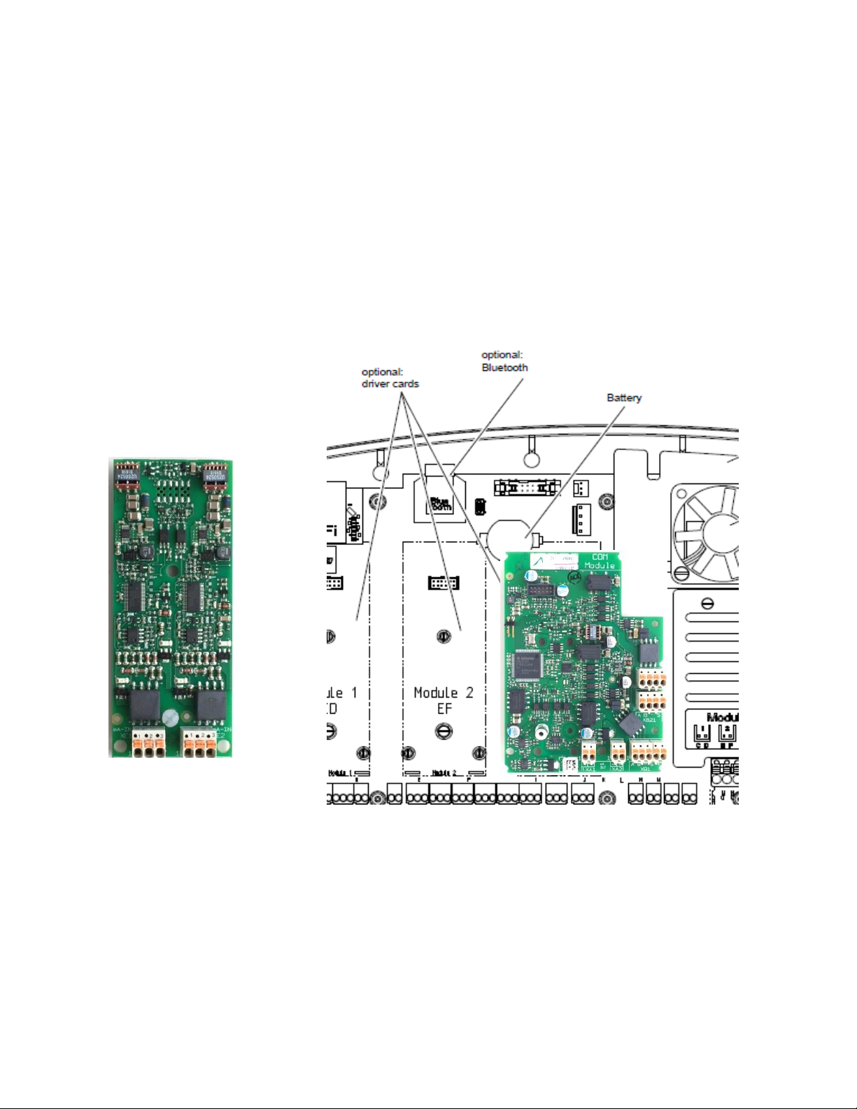
Dual 4-20mA Input
Driver
4 Com Module Installation
Com Module installed in expansion slot 3
From the factory, the Com Module will be installed in expansion slot 3. This card will not operate in expansion
slots 1 or 2. A plastic screw secures the card in place. The Com module may or may not have an optional driver
card attached. This optional driver is supplied with a plastic support screw as well. See optional driver card below.
Never install nor remove any driver or Com Module with power applied to the controller.
Instructions for installation, operation and maintenance of the 4-20mA input driver are in the controller operation
manuals.
The dual 4-20mA input driver can be installed in any expansion slot, Module 1, Module 2, Module 3 or in the feed
through slot on the communication driver card. See next page.
Page 4 of 30
Page 5
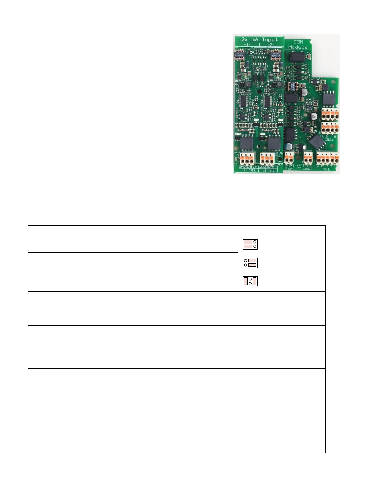
Driver card installed on Com module
Component
Function
Description
Connection
XT1
Modbus RTU Master to ext. Slave
(For Pyxis)
resistor jumpers
Def: Failsafe
1 3 5
2 4 6
1 3 5
2 4 6
1 3 5
2 4 6
Failsafe termination
Standard termination
or SW control
No termination
(park position)
XT2
Modbus RTU Slave to ext. Master
For Gateways and direct connection
resistor jumpers
Default: Standard?
XA1
mA output Channel 1
Pin 1 = (-)
Pin 2 = (+)
XA2
mA output Channel 2
Pin 1 = (-)
Pin 2 = (+)
XB11
Modbus RTU Master to ext. Slave
Pin 1 = (A)
Pin 2 = (B)
Pin 3 = (GND)
XB12
Modbus RTU Master to ext. Slave
Pin 1 = (shield)
Pin 2 = (+24)
XB21
Modbus RTU Slave to ext. Master
Pin 1 = (A)
Pin 2 = (B)
Pin 3 = (GND)
Pin 4 = (shield)
XB22
Modbus RTU Slave to ext. Master
For Daisy chain
XE1
mA input Channel 1
(optional driver)
Pin 1 = (GND)
Pin 2 = (mA input)
Pin 3 = (+23)
XE2
mA input Channel 2
(optional driver)
Pin 1 = (GND)
Pin 2 = (mA input)
Pin 3 = (+23)
When a Com Module is added to expansion slot #3, the dual 4-20mA
outputs acquire the identification letters I and J. These are the letter
assignments for any card installed in this slot.
If the dual 4-20mA input driver is installed onto the Com Module, it is
represented by the letters K and L.
The Dual 4-20mA input driver card is the only card that can be added
to the Com Module.
The Wiring Terminal Table shows all connections to the Com Module
Wiring Terminal Table:
Page 5 of 30
Page 6

5 Pyxis Sensor
Optional plug in 4-20mA input Module
Com Module
Pyxis sensor connection:
- XB11:01 -> Blue
- XB11:02 -> Yellow
Modbus RTU RS-485 Slave
Pyxis connection to Modbus Master RTU
Modbus RTU RS-485 Master
The Com card was constructed to accept a Modbus RTU version Pyxis Fluorometer. Connect the sensor as shown
below. This is currently the only input to the Master Modbus RTU terminals.
The fluorometer on input M can be monitored, used for control, show diagnostics and be calibrated through the
keypad or via a network connection using the Ethernet port or WiFi.
Consult the Aegis II and Pyxis manuals for programming instructions.
The Modbus RTU slave connections allow other entities to monitor this controller. The users can see the I/O
values but cannot edit them.
6 The RTU Slave Connection
Connect up to 120 communication driver card slaves to one master. The master can be the plant Modbus RTU
network or any number of Gateways. Currently, ProMinent has six gateways in stock that provide conversion to 3
protocols; Modbus TCP (Ethernet), BACnet IP (Ethernet) and BACnet MSTP (Serial). These gateways are available
with or without UL approval. The RTA brands are UL approved. The ADFweb brands are not UL approved and are
therefore available at a lesser price. See also section 9 for complete enclosure kits.
- XB11:03 -> Black
- XB12:01 (Blank)
- XB12:02 -> Red
Page 6 of 30
Page 7
Gateway devices require a separate DC power supply. See instructions accompanying the Gateway.
Controller Modbus RTU Comm Module
Gateway Slave to
TCP Master
External Power
Max 24V
V DC: Min 12V
Max 5V
The next few illustrations depict ADFweb brand, non-UL approved gateways which convert the Com Module
Modbus RTU Slave to another Protocol. The connection to the Com card is via the Modbus Master serial port on
the Gateway. The Gateway Slave port connects to the plant network Master. This port can be serial or Ethernet as
you choose.
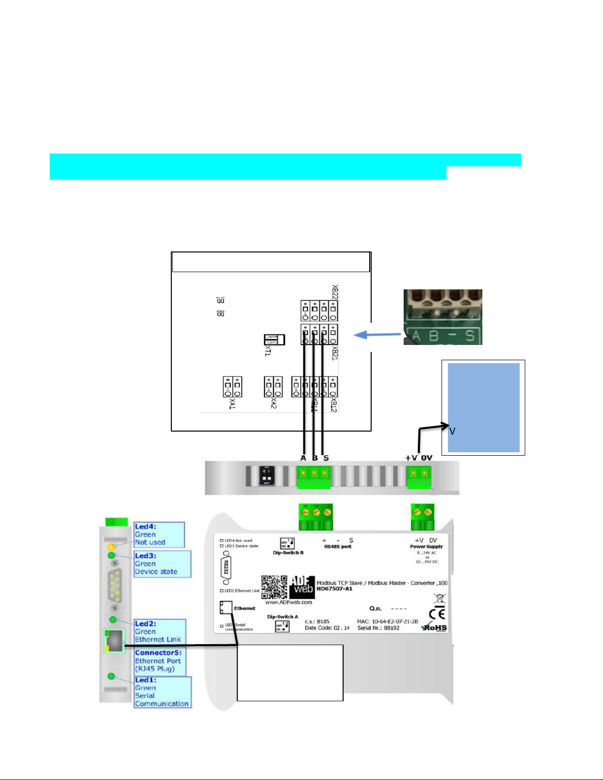
ADFweb Modbus TCP (Ethernet) Slave to Modbus Master. Not UL approved.
(Description explanation: ‘Modbus TCP Slave’ is the Gateway’s connection to the plant master via Ethernet.
‘Modbus Master’ describes the Gateway’s serial master to the communication card slave.)
Wiring the gateway terminal to Com card:
A+ to XB21 pin 1 (A), B - to pin 2 (B), Common (S) to pin 3 (Shown as a dash).
To load Configuration please refers to manufacture instruction manual MN67507_ENG section “UPDATE VIA
UDP:”
Gateway Part number:
1092941
Complete Kit part number:
1094286
See page 22 for kit
information.
Supply
V AC: Min 8V;
Customer Modbus-
Page 7 of 30
Page 8
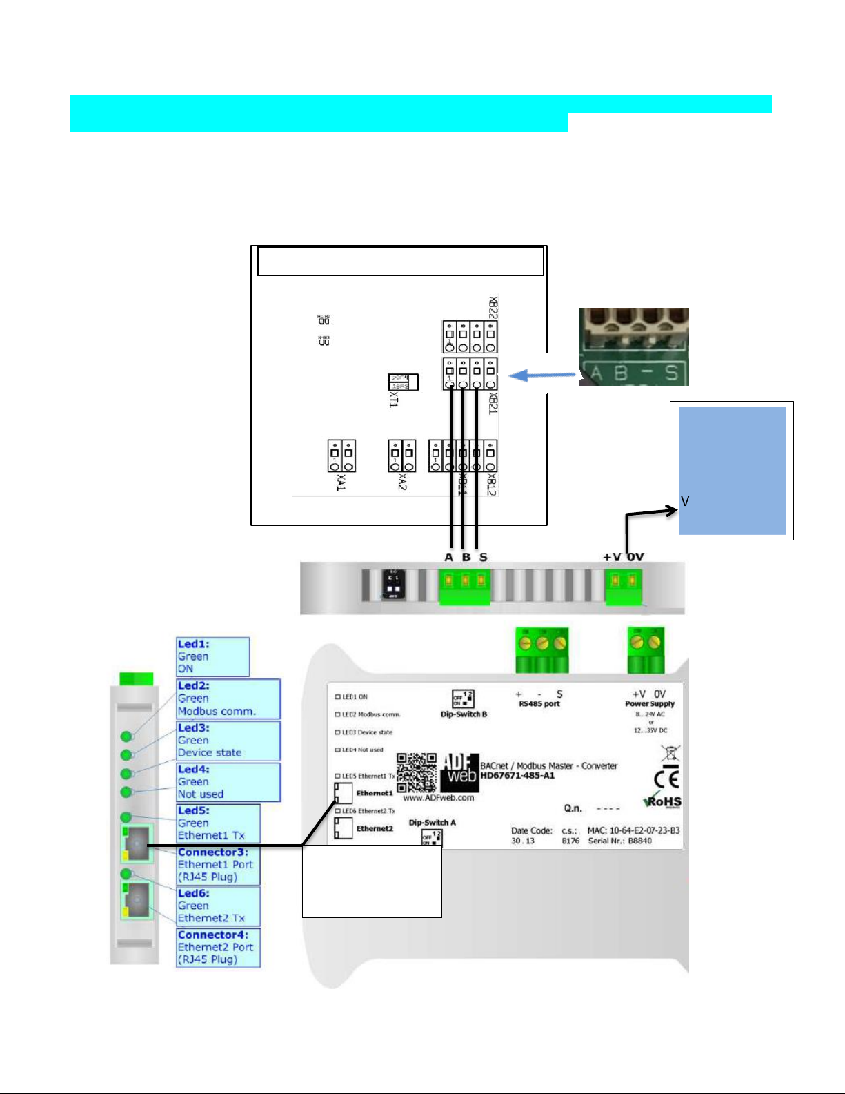
ADFweb BACnet IP (Ethernet) Slave to Modbus Master. Not UL approved.
Gateway Slave to
IP Master
External Power
Max 35V
Controller Modbus RTU Comm Module
(Description explanation: ‘BACnet IP Slave’ is the Gateway’s connection to the plant master via Ethernet. ‘Modbus
Master’ describes the Gateway’s serial master to the communication card slave.)
Gateway terminal to Com card: A+ to XB21 pin 1 (A), B - to pin 2 (B), Common (S) to pin 3 (Shown as a dash).
To load Configuration please refers to manufacture instruction manual MN67671_ENG section
“UPDATE DEVICE:”
Gateway Part number:
1092943
Complete kit part number:
1094287
See page 23 for kit
information.
Supply
V AC: Min 8V;
Max 24V
V DC: Min 12V
Customer BACnet
Page 8 of 30
Page 9
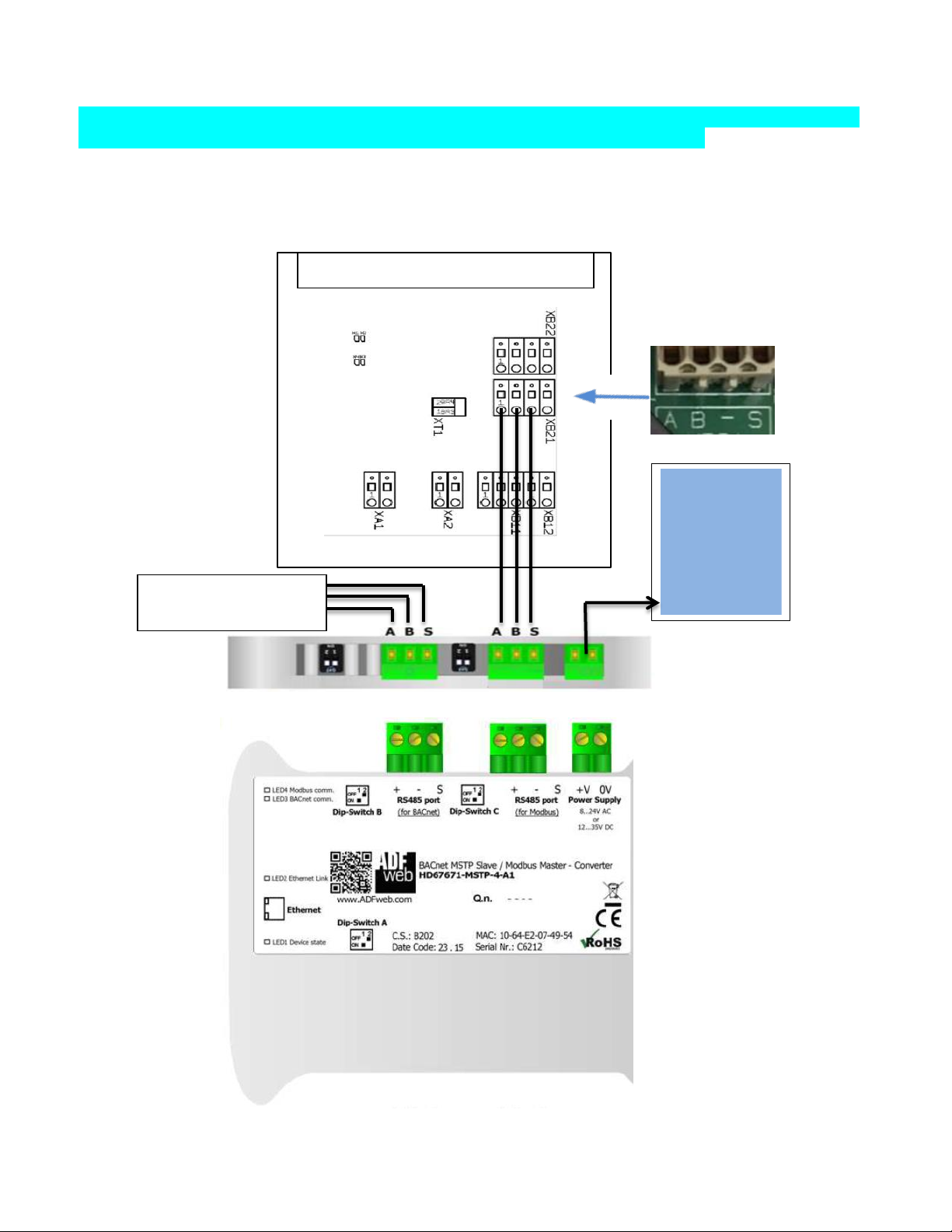
ADFweb BACnet MSTP (Serial) Slave to Modbus Master. Not UL approved.
External Power
Max 35V
To Customer BACnet
MSTP Master
Controller Modbus RTU Comm Module
(Description explanation: ‘BACnet MSTP Slave’ is the Gateway’s connection to the plant master via Serial wiring.
‘Modbus Master’ describes the Gateway’s serial master to the communication card slave.)
Gateway terminal to Com card: A+ to XB21 pin 1 (A), B - to pin 2 (B), Common (S) to pin 3 (Shown as a dash).
To load Configuration please refers to manufacture instruction manual MN67671_ENG section
“UPDATE DEVICE:”
Gateway Part number:
1092945
Complete Kit part number:
1094290
See page 21 for kit
information.
Supply
V AC: Min 8V;
Max 24V
V DC: Min 12V
Page 9 of 30
Page 10

Second controller with Comm
Controller Modbus RTU Comm Module
To Customer
Modbus-TCP
Master
Daisy Chain Example:
Page 10 of 30
Page 11

Controller Modbus RTU Comm Module
The RTA brand, UL approved models are shown here. Refer to manufacturer instructions for more detail.
External Power Supply
12-24VDC, 175 mA at
12VDC
To Customer
Modbus-TCP
Master
RTA Modbus TCP (Ethernet) Slave to Modbus Master. UL approved.
(Description explanation: ‘Modbus TCP Slave’ is the Gateway’s connection to the plant master via Ethernet.
‘Modbus Master’ describes the Gateway’s serial master to the communication card slave.)
Wiring the gateway terminal to Com card: +Tx to XB21 pin 1 (A), -Tx to pin 2 (B), Com to pin 3 (Shown as a dash).
To load a configuration, please refer to the manufacture’s instruction manual BFR3000NNA1_Userguide.
Gateway Part number:
1092940
Complete Kit part
Number: 1094288
See page 22 for kit
information.
Page 11 of 30
Page 12

Controller Modbus RTU Comm Module
RTA BACnet IP (Ethernet) Slave to Modbus Master. UL approved.
External Power Supply
12-24VDC, 175 mA at
12VDC
To Customer
BACnet IP Master
(Description explanation: ‘BACnet IP Slave’ is the Gateway’s connection to the plant master via Ethernet.
‘Modbus Master’ describes the Gateway’s serial master to the communication card slave.)
Wiring the gateway terminal to Com card: +Tx to XB21 pin 1 (A), -Tx to pin 2 (B), Com to pin 3 (Shown as a dash).
To load Configuration please refers to manufacture instruction manual 460MMBS-NNA1_Userguide.
Gateway Part number:
1092942
Complete kit part number:
1094289
See page 23 for kit
information.
Page 12 of 30
Page 13

Controller Modbus RTU Comm Module
RTA BACnet MSTP (Serial) to Modbus Master. UL approved.
External Power Supply
12-24VDC, 175 mA at
12VDC
To Customer
BACnet-MSTP
(Description explanation: ‘BACnet MSTP Slave’ is the Gateway’s connection to the plant master via Serial wiring.
‘Modbus Master’ describes the Gateway’s serial master to the communication card slave.)
Wiring the gateway terminal to Com card: +Tx to XB21 pin 1 (A), -Tx to pin 2 (B), Com to pin 3 (Shown as a dash).
To load Configuration please refers to manufacture instruction manual 460MMBMS-NNA4_Userguide.
Gateway Part number:
1092946
Complete Kit part number:
1094291
See page 21 for kit
information.
Page 13 of 30
Page 14

7 Gateway Settings
Parameter
Standard Value
Serial Mode
RS-485 differential
Termination
Disabled
Serial Format
8 data bits
Odd parity
1 stop bit
Baud rate
19200
Slave Address
10
The implementation of the Modbus interface is based on the following standards:
http://www.modbus.org/docs/Modbus_over_serial_line_V1_02.pdf. More information about Modbus can be
found at www.modbus.org.
The ProMinent Aegis II Modbus interface supports RS-485 interface standard
- Half-duplex, 2-wire technology
- twisted pair cable [twisted pair]
- Differential voltage level ± 5 V
- Cable length up to 1200 m
The device can be connected as an endpoint slave (either with one of the connections) or
as [Daisy-Chain-Slave] (with both connections).
Default-Connection-Settings:
This is the default configuration for Aegis II controller Modbus interface; this configuration can be modified in
System -> Communication Menu
Supported Modbus commands:
Function Code: Read-Holding-Register 0x03 (3)
Note: In order for your customer to have access to all Modbus registers in the Aegis II controller, you will need to
have a Modbus driver card with firmware version 1.0.23.0 or newer and Aegis II controller firmware 18.04.14.00
(2018/April/14) or newer.
Page 14 of 30
Page 15

8 The Inputs and Outputs
Register Address
(Starting from 0)
Register Number
(Starting from 1)
Parameter
Format (Type)
Access Level
R= Read
W = Write
Byte order
info
500
501
Actual Measure
Value on ‘A’ input
FLOAT32
R
BADC
502
503
Actual Measure
Value on ‘B’ input
FLOAT32
R
BADC
504
505
Actual Measure
Value on ‘C’ input
FLOAT32
R
BADC
506
507
Actual Measure
Value on ‘D’ input
FLOAT32
R
BADC
508
509
Actual Measure
Value on ‘E’ input
FLOAT32
R
BADC
510
511
Actual Measure
Value on ‘F’ input
FLOAT32
R
BADC
512
513
Actual Measure
Value on ‘G’ input
FLOAT32
R
BADC
514
515
Actual Measure
Value on ‘H’ input
FLOAT32
R
BADC
516
517
Actual Measure
Value on ‘I’ input
FLOAT32
R
BADC
Assigned to
4-20mA output 1
(Comm Module)
518
519
Actual Measure
Value on ‘J’ input
FLOAT32
R
BADC
Assigned to
4-20mA output 2
(Comm Module)
520
521
Actual Measure
Value on ‘K’ input
FLOAT32
R
BADC
Assigned to
4-20mA input 1
(Comm Module)
522
523
Actual Measure
Value on ‘L’ input
FLOAT32
R
BADC
Assigned to
4-20mA input 2
(Comm Module)
524
525
Actual Measure
Value on ‘M’ input
FLOAT32
R
BADC
Modbus Pyxis
Sensor
526
527
Actual Measure
Value on ‘N’ input
FLOAT32
R
BADC
Register Address
(Starting from 0)
Register Number
(Starting from 1)
Parameter
Format
(Type)
Access Level
R= Read
Byte order
info
552
553
Output ‘Relay 1’
FLOAT32
R
BADC
ON/OFF: ON=1, OFF =0
554
555
Output ‘Relay 2’
FLOAT32
R
BADC
ON/OFF: ON=1, OFF =0
556
557
Output ‘Relay 3’
FLOAT32
R
BADC
ON/OFF: ON=1, OFF =0
558
559
Output ‘Relay 4’
FLOAT32
R
BADC
ON/OFF: ON=1, OFF =0
560
561
Output ‘Relay 5’
FLOAT32
R
BADC
ON/OFF: ON=1, OFF =0
562
563
Output ‘P6’
FLOAT32
R
BADC
ON/OFF: ON=1, OFF =0
Pulse: 0-100 %
564
565
Output ‘P7’
FLOAT32
R
BADC
ON/OFF: ON=1, OFF =0
Pulse: 0-100 %
566
567
Output ‘P8’
FLOAT32
R
BADC
ON/OFF: ON=1, OFF =0
Pulse: 0-100 %
568
569
Output ‘P9’
FLOAT32
R
BADC
ON/OFF: ON=1, OFF =0
Pulse: 0-100 %
Analog Inputs/Outputs:
Digital Outputs:
Page 15 of 30
Page 16

Register Address
(Starting from 0)
Register Number
(Starting from 1)
Parameter
Format (Type)
Access Level
R= Read
Byte order
info
528
529
Input ‘O’
FLOAT32
R
BADC
Contact: Closed=1,
Opened=0
Water meter/turbine:
Volume
530
531
Input ‘P’
FLOAT32
R
BADC
Contact: Closed=1,
Opened=0
Water meter/turbine:
Volume
532
533
Input ‘Q’
FLOAT32
R
BADC
Contact: Closed=1,
Opened=0
Water meter/turbine:
Volume
534
535
Input ‘R’
FLOAT32
R
BADC
Contact: Closed=1,
Opened=0
Water meter/turbine:
Volume
536
537
Input ‘S’
FLOAT32
R
BADC
Contact: Closed=1,
Opened=0
Water meter/turbine:
Volume
538
539
Input ‘T’
FLOAT32
R
BADC
Contact: Closed=1,
Opened=0
Water meter/turbine:
Volume
540
541
Input ‘U’
FLOAT32
R
BADC
Contact: Closed=1,
Opened=0
Water meter/turbine:
Volume
542
543
Input ‘V’
FLOAT32
R
BADC
Contact: Closed=1,
Opened=0
Water meter/turbine:
Volume
544
545
Input ‘W’
FLOAT32
R
BADC
Contact: Closed=1,
Opened=0
Water meter/turbine:
Volume
546
547
Input ‘X’
FLOAT32
R
BADC
Contact: Closed=1,
Opened=0
Water meter/turbine:
Volume
548
549
Input ‘Y’
FLOAT32
R
BADC
Contact: Closed=1,
Opened=0
Water meter/turbine:
Volume
550
551
Input ‘Z’
FLOAT32
R
BADC
Contact: Closed=1,
Opened=0
Water meter/turbine:
Volume
Digital Inputs:
Page 16 of 30
Page 17

Register Address
(Starting from 0)
Register Number
(Starting from 1)
Parameter
Format (Type)
Access Level
R= Read
Byte order
info
570
571
Input ‘A’, High Alarm
FLOAT32
R
BADC
572
573
Input ‘A’, Low Alarm
FLOAT32
R
BADC
574
575
Input ‘B’, High Alarm
FLOAT32
R
BADC
576
577
Input ‘B’, Low Alarm
FLOAT32
R
BADC
578
579
Input ‘C’, High Alarm
FLOAT32
R
BADC
580
581
Input ‘C’, Low Alarm
FLOAT32
R
BADC
582
583
Input ‘D’, High Alarm
FLOAT32
R
BADC
584
585
Input ‘D’, Low Alarm
FLOAT32
R
BADC
586
587
Input ‘E’, High Alarm
FLOAT32
R
BADC
588
589
Input ‘E’, Low Alarm
FLOAT32
R
BADC
590
591
Input ‘F’, High Alarm
FLOAT32
R
BADC
592
593
Input ‘F’, Low Alarm
FLOAT32
R
BADC
594
595
Input ‘G’, High Alarm
FLOAT32
R
BADC
596
597
Input ‘G’, Low Alarm
FLOAT32
R
BADC
598
599
Input ‘H’, High Alarm
FLOAT32
R
BADC
600
601
Input ‘H’, Low Alarm
FLOAT32
R
BADC
602
603
Input ‘I’, High Alarm
FLOAT32
R
BADC
604
605
Input ‘I’, Low Alarm
FLOAT32
R
BADC
606
607
Input ‘J’, High Alarm
FLOAT32
R
BADC
608
609
Input ‘J’, Low Alarm
FLOAT32
R
BADC
610
611
Input ‘K’, High Alarm
FLOAT32
R
BADC
612
613
Input ‘K’, Low Alarm
FLOAT32
R
BADC
614
615
Input ‘L’, High Alarm
FLOAT32
R
BADC
616
617
Input ‘L’, Low Alarm
FLOAT32
R
BADC
618
619
Input ‘M’, High Alarm
FLOAT32
R
BADC
620
621
Input ‘M’, Low Alarm
FLOAT32
R
BADC
622
623
Input ‘N’, High Alarm
FLOAT32
R
BADC
624
625
Input ‘N’, Low Alarm
FLOAT32
R
BADC
Register Address
(Starting from 0)
Register Number
(Starting from 1)
Parameter
Format
(Type)
Access Level
R= Read
Byte order
info
626
627
Input ‘O’, Total Counter
FLOAT32
R
BADC
628
629
Input ‘P’, Total Counter
FLOAT32
R
BADC
630
631
Input ‘Q’, Total Counter
FLOAT32
R
BADC
632
633
Input ‘R’, Total Counter
FLOAT32
R
BADC
634
635
Input ‘S’, Total Counter
FLOAT32
R
BADC
636
637
Input ‘T’, Total Counter
FLOAT32
R
BADC
638
639
Input ‘U’, Total Counter
FLOAT32
R
BADC
640
641
Input ‘V’, Total Counter
FLOAT32
R
BADC
Alarms:
Total Counter ( if these inputs are configurated as Daily counter):
If not configurated as daily counter the register value will be NULL
Page 17 of 30
Page 18

Setpoints:
Register Address
(Starting from 0)
Register Number
(Starting from 1)
Parameter
Format (Type)
Access Level
R= Read
Byte order
info
642
643
R 1 - high set point
FLOAT32
R
BADC
644
645
R 1 - low set point
FLOAT32
R
BADC
646
647
R 2 - high set point
FLOAT32
R
BADC
648
649
R 2 - low set point
FLOAT32
R
BADC
650
651
R 3 - high set point
FLOAT32
R
BADC
652
653
R 3 - low set point
FLOAT32
R
BADC
654
655
R 4 - high set point
FLOAT32
R
BADC
656
657
R 4 - low set point
FLOAT32
R
BADC
658
659
R 5 - high set point
FLOAT32
R
BADC
660
661
R 5 - low set point
FLOAT32
R
BADC
662
663
P 6 - high set point
FLOAT32
R
BADC
664
665
P 6 - low set point
FLOAT32
R
BADC
666
667
P 7 - high set point
FLOAT32
R
BADC
668
669
P 7 - low set point
FLOAT32
R
BADC
670
671
P 8 - high set point
FLOAT32
R
BADC
672
673
P 8 - low set point
FLOAT32
R
BADC
674
675
P 9 - high set point
FLOAT32
R
BADC
676
677
P 9 - low set point
FLOAT32
R
BADC
Register Address
(Starting from 0)
Register Number
(Starting from 1)
Parameter
Format (Type)
Access Level
R= Read
Byte order
info
678
679
Input ‘A’
UINT16
R
BADC
679
680
Input ‘B’
UINT16
R
BADC
680
681
Input ‘C’
UINT16
R
BADC
681
682
Input ‘D’
UINT16
R
BADC
682
683
Input ‘E’
UINT16
R
BADC
683
684
Input ‘F’
UINT16
R
BADC
684
685
Input ‘G’
UINT16
R
BADC
685
686
Input ‘H’
UINT16
R
BADC
686
687
Input ‘I’
UINT16
R
BADC
687
688
Input ‘J’
UINT16
R
BADC
688
689
Input ‘K’
UINT16
R
BADC
689
690
Input ‘L’
UINT16
R
BADC
690
691
Input ‘M’
UINT16
R
BADC
691
692
Input ‘N’
UINT16
R
BADC
692
693
Input ‘O’
UINT16
R
BADC
693
694
Input ‘P’
UINT16
R
BADC
694
695
Input ‘Q’
UINT16
R
BADC
695
696
Input ‘R’
UINT16
R
BADC
696
697
Input ‘S’
UINT16
R
BADC
697
698
Input ‘T’
UINT16
R
BADC
698
699
Input ‘U’
UINT16
R
BADC
699
700
Input ‘V’
UINT16
R
BADC
700
701
Input ‘W’
UINT16
R
BADC
701
702
Input ‘X’
UINT16
R
BADC
702
703
Input ‘Y’
UINT16
R
BADC
SETPOINTS ONLY WORK IF “SET FEED MODE” IS SELECTED AS
Setpoints only work if “SET FEED MODE” is selected as a “SENSOR CONTROL” OR “WATER METER”
Error Message:
Page 18 of 30
Page 19

703
704
Input ‘Z’
UINT16
R
BADC
704
705
Output ‘R1’
UINT32
R
BADC
706
707
Output ‘R2’
UINT32
R
BADC
708
709
Output ‘R3’
UINT32
R
BADC
710
711
Output ‘R4’
UINT32
R
BADC
712
713
Output ‘R5’
UINT32
R
BADC
714
715
Output ‘P6’
UINT32
R
BADC
716
717
Output ‘P7’
UINT32
R
BADC
718
719
Output ‘P8’
UINT32
R
BADC
720
721
Output ‘P9’
UINT32
R
BADC
722
723
System
UINT32
R
BADC
Input A-Z States:
S_enabled 0x0001 disabled parameters are not logged, do not display, cannot be used in commands
S_alarmed 0x0002 execute alarm action bit(s)
S_events 0x0004 timed events exist for this relay
S_arelay 0x0008 trip alarm relay on alarm // if Alarm Relay is set to Yes in Alarm setting
S_off 0x0010 Actively Turned OFF by Interlock, Lockout, Alarmed (reference output states for cause)
S_stopped 0x0020 HOA set to STOP // not applicable to Aegis II
S_manual 0x0040 HOA set to MANUAL // not applicable to Aegis II
S_disconn 0x0080 Serial sensor or Modbus Driver not responding
Output R1-R5 and P6-P9 States:
Some of the bits reflect configuration (C_offonalarm), some reflect control state (C_rlocked)
Here is the example how to use these bitwise masking: If mask for bit 0 you will get ON/OFF state.
Note: in order to extract a subset of the bits in the value do Bitwise ANDing
Mask: 0x00000001b (C_on)
Value: 0x01010101b (R1 register 704 value)
Result: 0x00000001b (the result shows the relay is ON)
C_on 0x00000001 current state of Relay ON|OFF or Pulse Drive, also Prime ON/OFF
C_ilocked 0x00000002 interlocked on contact set (U to Z)
C_tlocked 0x00000004 lockout on time
C_vary 0x00000008 varying cycle controls, adjusts setpoints (unused for PID)
C_do 0x00000010 Control Field Frequency output is set as Digital Output and also for Analog Outputs
C_offonalarm 0x00000020 turned OFF on alarm
C_rlocked 0x00000040 interlocked by another relay
Page 19 of 30
Page 20

C_meters 0x00000080 control by Volume & Time
C_special 0x00000100 control by special control
C_sequence 0x00000200 2nd phase of an Q:P sequential volume control; ON for 'P'
C_forcedon 0x00000400 prebleed has turned relay ON
C_owed 0x00000800 time owed, count down if not blocked
C_blocking 0x00002000 Output R1 to R5, P6 to P9 is blocking another relay
C_oxidant 0x00004000 one of assist, pH lockout or alt. control events is active // not applicable to Aegis II
C_delayed 0x00008000 User set delay on flow switch // not applicable to Aegis II
C_drvfault 0x00010000 Driver card communication timeout (implies no card, card fault)
C_prebleed 0x00020000 ON because prebleed active on time or uS
C_ontrip 0x00100000 Set when ON setpoint exceeded, stays On until OFF setpoint exceeded
C_eventsp 0x00200000 Set when Oxidant Event Setpoints override control setpoints
C_latched 0x00800000 Contact Set controls, retains state during deadtime
System State:
SYS_USB 0x00000400 USB host port active (USB thumb drive plugged in), file uploading, Pumps OFF, A/D blocked
SYS_LOCKED 0x00004000 LOCKOUT_LIMIT password fails, reset @ 7:00AM or power cycle
SYS_NOUSD 0x08000000 File System faults, no USD
Page 20 of 30
Page 21

9 Gateway Enclosure Kits
Kits include the gateway, a 24VDC power supply, serial terminations mounted in a Nema 4X enclosure.
BACnet MSTP Converter Terminal Box
Kit part number 1094290 includes the ADFweb (not UL approved) BACnet MSTP Slave to Modbus
Master gateway, part number 1092945. See page 9 for gateway information.
Kit part number 1094291 includes the RTA (UL approved) BACnet MSTP Slave to Modbus Master
gateway, part number 1092946. See page 13 for gateway information.
Dimensions: 10.88 x 7.38 x 9.06 Construction: Fibox NEMA 4X Polycarbonate
Page 21 of 30
Page 22

MODBUS TCP Converter Terminal Box
Kit part number 1094286 includes the ADFweb (not UL approved) Modbus TCP Slave to Modbus
Master gateway, part number 1092941. See page 7 for gateway information.
Kit part number 1094288 includes the RTA (UL approved) Modbus TCP to Modbus Master
gateway, part number 1092940. See page 11 for gateway information.
Dimensions: 10.88 x 7.38 x 9.06 Construction: Fibox NEMA 4X Polycarbonate
Page 22 of 30
Page 23

BACnet IP Converter Terminal Box
Kit part number 1094287 includes the ADFweb (not UL approved) BACnet IP Slave to Modbus
Master gateway, part number 1092943. See page 8 for gateway information.
Kit part number 1094289 includes the RTA (UL approved) BACnet IP Slave to Modbus Master
gateway, part number 1092942. See page 12 for gateway information.
Dimensions: 10.88 x 7.38 x 9.06 Construction: Fibox NEMA 4X Polycarbonate
Page 23 of 30
Page 24

10 Replacement Parts
PFC Part #
Description
1092940
Modbus TCP Slave / Modbus Master – Converter UL Certified (RTA brand)
1092941
Modbus TCP Slave / Modbus Master – Converter (ADFweb brand)
1092942
BACnet IP Slave / Modbus Master – Converter UL Certified (RTA brand)
1092943
BACnet IP Slave / Modbus Master – Converter (ADFweb brand)
1092964
BACnet MSTP Slave / Modbus Master – Converter UL Certified (RTA brand)
1092965
BACnet MSTP Slave / Modbus Master – Converter (ADFweb brand)
The following list includes all parts necessary to build a complete enclosure, including the power supply, but does
not include the gateway. Gateway part numbers below.
ProMinent Gateway part numbers
Page 24 of 30
Page 25

11 Technical Support
If the communication link is not working, refer to this checklist.
Try to swap the serial connection
Are the wires connected to the correct terminals?
Do the default settings listed on page 14 agree with the controller’s System Configure page?
Do these settings agree with the Gateway or other Master settings?
Addresses must not be the same
If using a gateway, did you load a configuration into the gateway according to the manufacturer’s instruction?
Can you test the Master line with another Slave?
Test the Com Module using the instructions in section 12: Communication Module Register Test
Page 25 of 30
Page 26

12 Communication Module Register Test
Converter Module
Printer style USB cable
Test the Modbus registers via the Com Module on an Aegis II using a TTL/RS485 USB dual function dual
protection USB turn 485 module FT232 chip module.
You will need the converter module, a Printer USB cable and Fenix or similar software.
You can purchase this converter module from NewEgg.com. Use the link below.
You will also need a Printer style USB cable. (Note the USB port on the card).
https://www.newegg.com/Product/Product.aspx?Item=9SIAAZM4RC0009&ignorebbr=1&nm_mc=KNCGoogleMKP-PC&cm_mmc=KNC-GoogleMKP-PC-_-pla-_-EC+-+Test+%26+Measurement-_9SIAAZM4RC0009&gclid=EAIaIQobChMIxvql-5yP2gIVgj2BCh0xwQ6IEAkYDiABEgILKvD_BwE&gclsrc=aw.ds
Page 26 of 30
Page 27

Download Fenix Software. Use this link:
https://sourceforge.net/projects/fenixmodbus/?source=typ_redirect
Press the Green Download button.
You may need IT permission to install the Fenix program on your company laptop. Check with your company IT
department!
Connect as shown.
Use the Printer style USB cable to connect the
converter to your PC.
Open the Fenix software on the PC.
Create a new project.
Page 27 of 30
Page 28

Fill in the project page. Press Save.
Create a directory to store your project. Ex: C:\Users\peters\Documents\Controllers\Software\Fenix
3.0.8\Projects and supply a name.
Page 28 of 30
Page 29

Select Add Connection. Provide a name, choose Modbus Master RTU for driver name, and all settings as below.
The COM port will depend on how your PC chooses this device. Use your Device Manager to look at the USB
connections when you plug in the cable. Press OK. (Hint: Type ‘device manager’ in your search box)
Right click on the Connection you created and select Add Device.
Name the device based on where the Com Module is located. Use the controller System Communication
properties to find the Device Address and enter it here.
Add all pertinent I/O points using Add Tag from the Device menu.
Page 29 of 30
Page 30

The starting address is 501 (which stands for 500 and 501). Consult section # 8 Inputs and Outputs for a list of I/O
points.
Input A is 501, B is 503, C is 505 etc.
Select the Table View icon to view the I/O
Highlight the Connection (Office in my example) and use the start and stop icons to run/stop the data acquisition.
Save your Project at this point. If you forget, all will be lost.
Next session, select Open rather than New.
ProMinent Fluid Controls, Inc.
136 Industry Drive
Pittsburgh, PA 15275-1014
412.787.2484
www.proMinent.us
Page 30 of 30
 Loading...