

Page 1
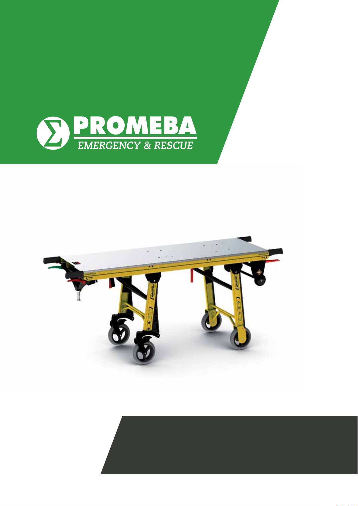
USER GUIDE
INCUBATOR STRETCHER // PC-615
Review 11/18
Page 2

Page 3
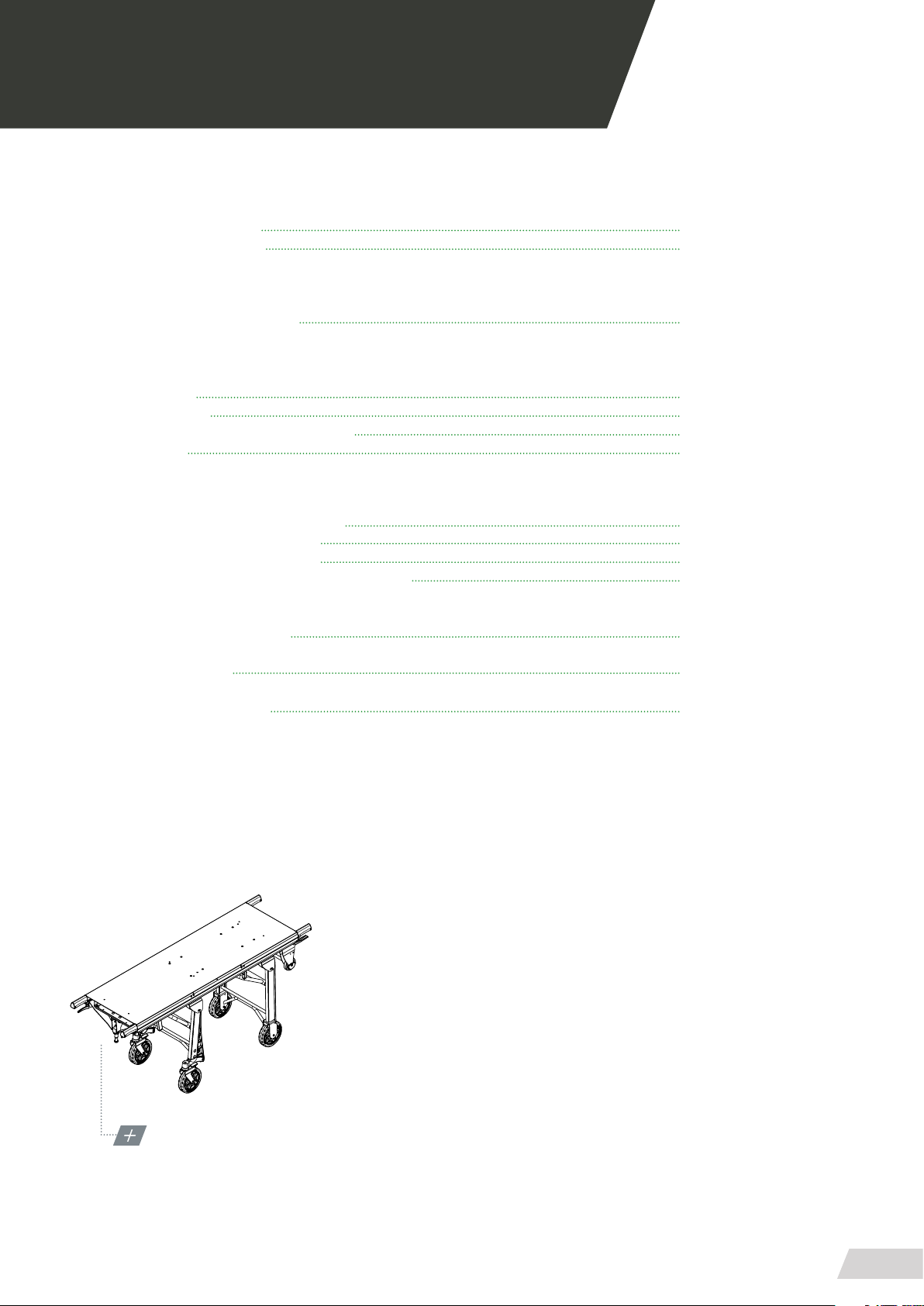
USER MANUAL // STRETCHER PC-615
Review 11/18
INDEX
01 INTRODUCTION
01.1 Using this manual 05
01.2 Technical datasheet 07
02 INSTALLATION
02.1 Transport and unpacking 09
03 OPERATION
03.1 Elements 11
03.2 Commands 13
03.3 Loading and unloading operation 14
03.4 Tensors 15
04 MOUNTING AND COMPONENTS
04.1 General view STRETCHER PC-615 17
04.2 Telescopic Hand Grips PC-615 20
04.8 Standard xed leg set PC-615 22
04.9 Standard revolving standard leg set PC-615 24
05 GENERAL MAINTENANCE 26
06 LEGAL NOTICES 27
07 PRODUCT WARRANTY 28
MODEL PC-615
STANDARD CONFIGURATION
3
Page 4

Page 5

USER MANUAL // STRETCHER PC-615
Review 11/18
01 INTRODUCTION
01.1 Using this manual
This manual provides using and maintenance instructions of the product, as well as the way of xing minor
faults that could appear.
It is recommended before the operation of the product
to read carefully this manual in order to avoid damages
caused by a misuse.
Do not lose this document, it should be accessible to
any doubt that could appear by medical personnel.
Remember that a good use and maintenance are necessary for the proper operation of the product.
Each product incorporates an identication sticker with
the serial number and the model. Keep these numbers
so that they can be indicated to the dealer if necessary.
5
Page 6

Page 7
USER MANUAL // STRETCHER PC-615
Review 11/18
01 INTRODUCTION
01.2 Technical data sheet
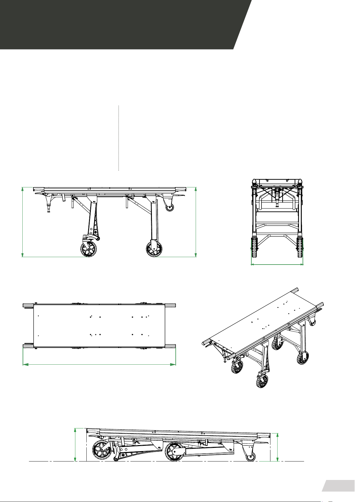
MEASURES AND FEATURES // PC-615
LENGHT 1920 mm INTERMEDIATE STOP 694 mm
WIDTH 580 mm FOLDED HEIGHT 300-330 mm
HEIGHT 830 mm MAX. LOAD 250 Kg
WEIGHT 45 Kg
830
192
830
0
58
0
330
300
7
Page 8

Page 9
USER MANUAL // STRETCHER PC-615
Review 11/18
02 INSTALATION
02.1 Transporting and unpacking
First remove the packaging carefully to prevent damage to the exterior of the stretcher.
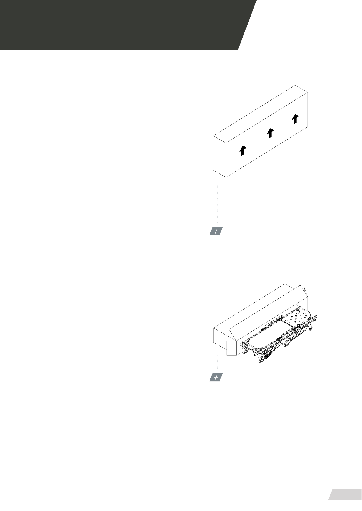
1. Transporting
· Always x the load, if piling up is necessary always
follow the scheme shown.
· Transport the leveled load and following all precepts
and rules for the transport of loads.
2. Unpacking
· Place the box on a at, stable surface and open the
seal being careful not to damage the inside.
· Remove the stretcher from the inside of the load as
shown in the scheme below.
Each stretcher has been minutely examined when leaving the factory. To ensure that it has not been deteriorated during transport, please carefully inspect the
outside and the inside, and in case of nding any imperfection, immediately contact the installer.
For an optimum operation, the stretcher must be leveled.
PACKING UNIT
RRESPECT THE PACKING’S TRANSPORT POSITION
PRODUCT’S UNPACKING
ALWAYS USE A FLAT BASE SUPPORT
9
Page 10

Page 11
USER MANUAL // STRETCHER PC-615
Review 11/18
03 OPERATING
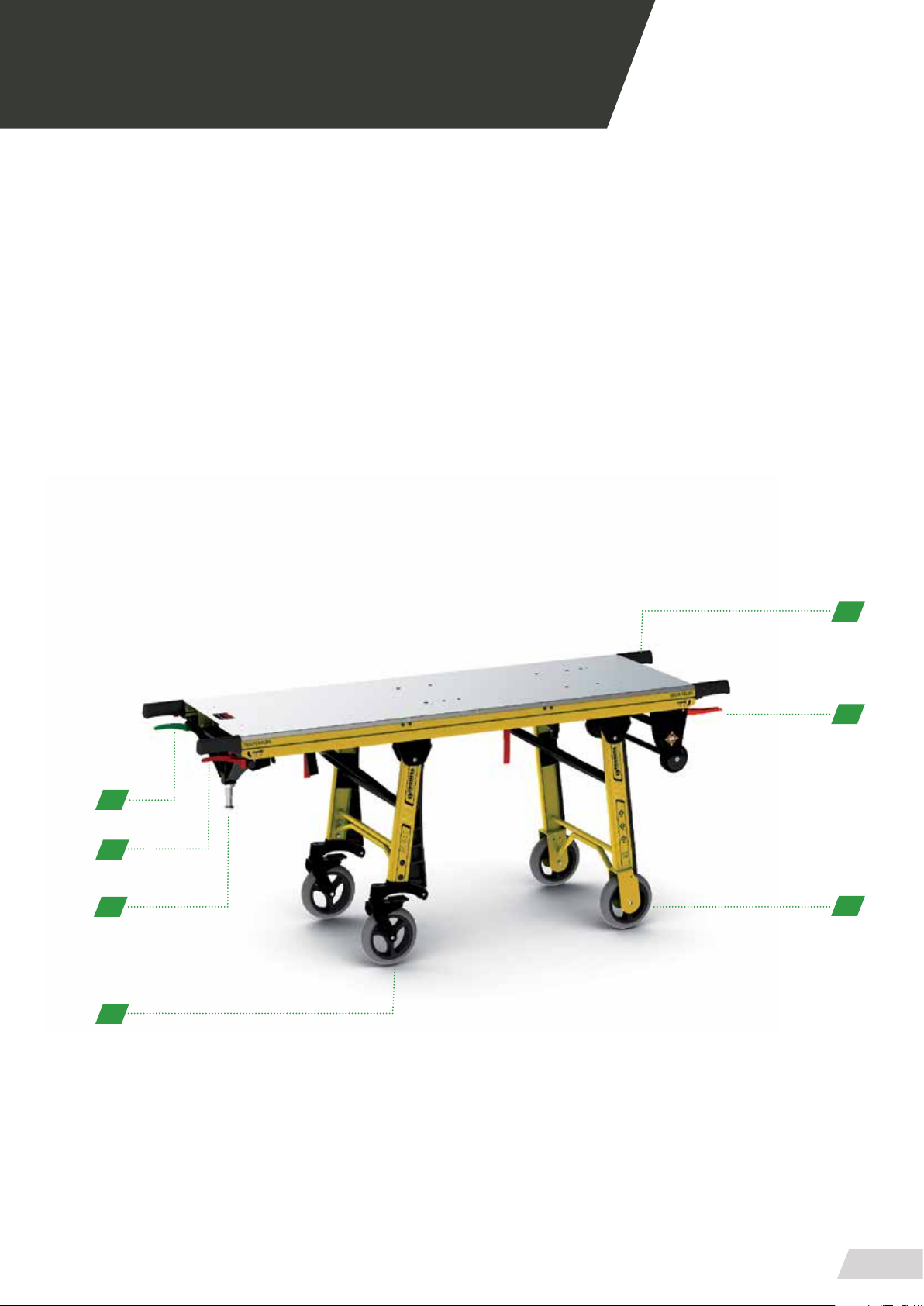
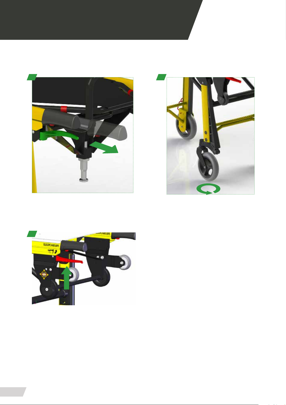
03.1 Elements PC-615
1. Telescopic handles
2. Front leg holding position operating lever
3. Front wheels brake
4. Rear revolving wheels
5. Third anchor point
6. Front leg operating lever
7. Rear leg operating lever
1
2
7
6
5
4
3
11
Page 12
USER MANUAL // STRETCHER PC-615
Review 11/18
03 OPERATING
03.1 Elements PC-615
1 5
1
12
Page 13
USER MANUAL // STRETCHER PC-615
Review 11/18
03 OPERATING
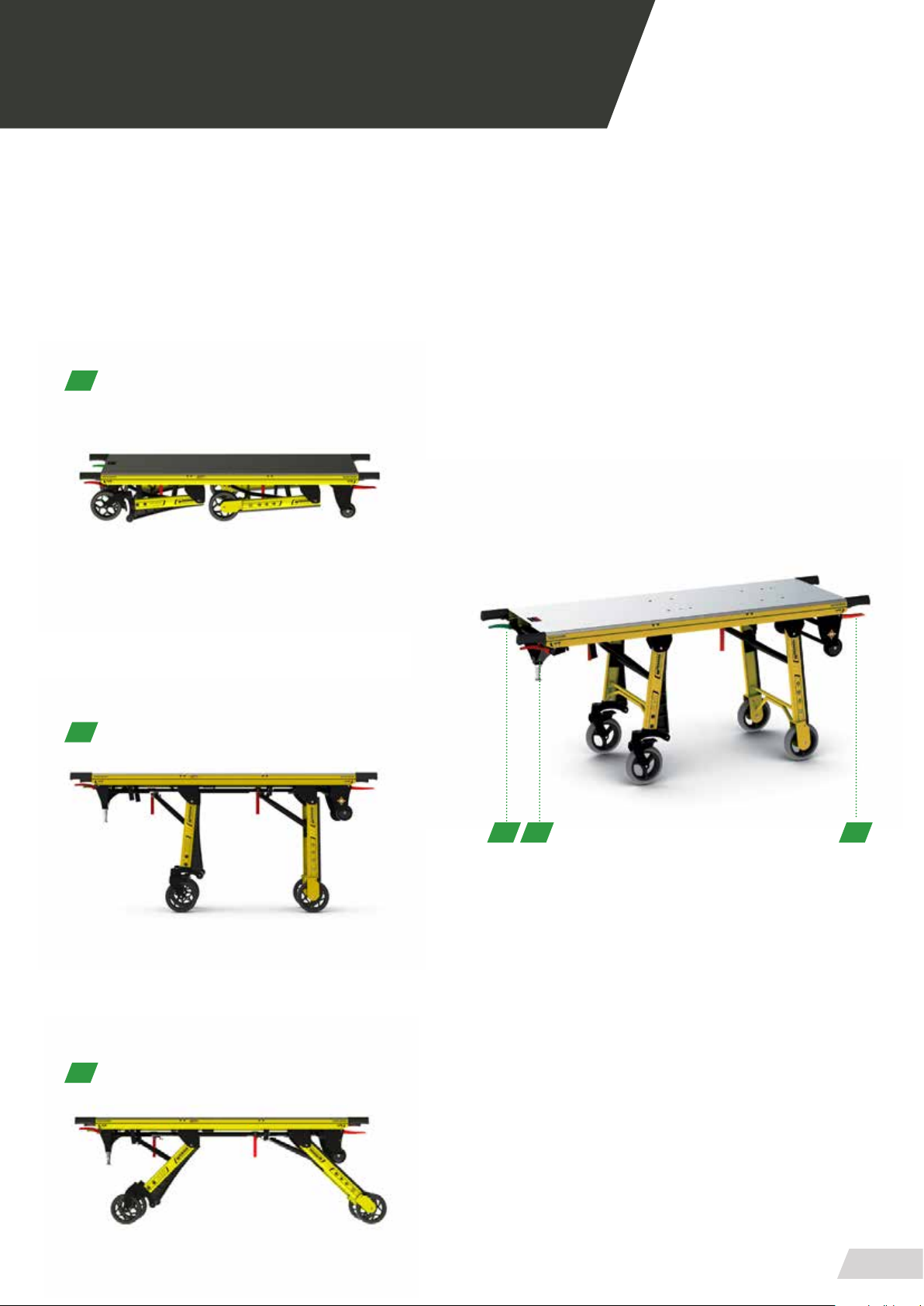
03.2 Commands PC-615
01. REAR LEGS UNLOCKING LEVER
Green, located on the stretcher’s left side. The legs of the
rear side will unlock by operating the lever in order to place
the stretcher in loading and unloading position.
01
02. FRONT LEGS UNLOCKING LEVER
Red, located on the stretcher’s right side. The legs of the
front side will unlock by operating it in order to place the
stretcher in loading and unloading position.
02
03. HOLDING POSITION LEVER
Red, located on the front right side. It allows a second position which facilitates the loading of the patient.
01 02 03
03
13
Page 14
USER MANUAL // STRETCHER PC-615
Review 11/18
03 OPERATING
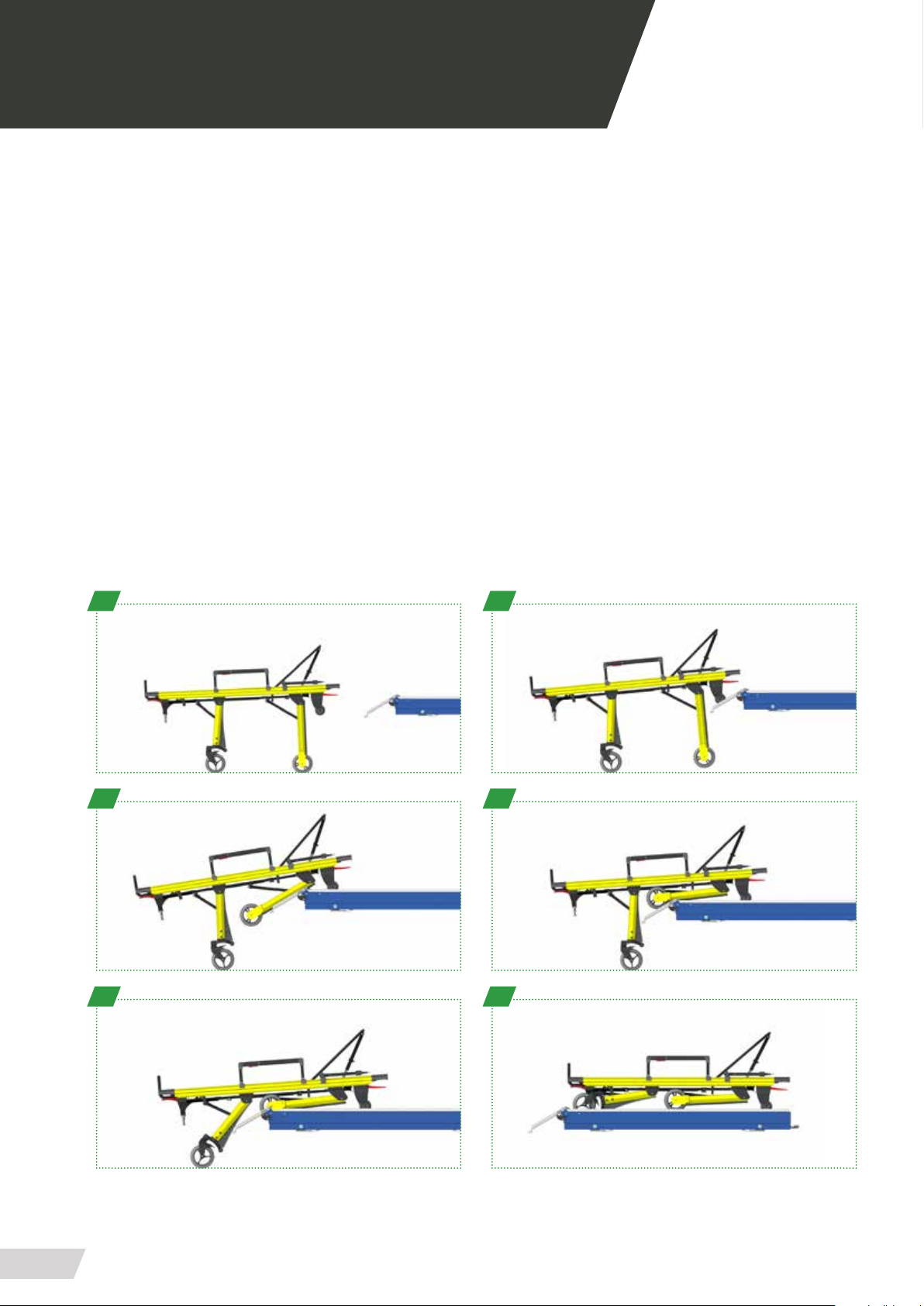
03.3 Loading and unloading operation
LOADING
· Open the loading ramp of the bench/rail (A)
· Place the stretcher head-on in relation to the loading axle of the bench (A)
· Approach the stretcher until the front wheels have contact with the loading ramp (B)
· Operate the right lever (RED) to unlock the front wheels (C)
· Decisively push to slide the stretcher into the ambulance (D)
· As the rear leg approaches, press the left lever (GREEN) to release the legs (E)
· Keep pushing until the stretcher is fully loaded (E)
· Pay attention to the third anchor point, you may heard a CLICK (in case of being installed)
· Close the loading ramp
UNLOADING
· Open the loading ramp of the bench/rail
· Release the stretcher’s closure by operating the lever (in case of being installed)
· Pull the stretcher. It will slide outward, hold it with the hands
· Fold the loading ramp
A B
C D
E F
14
Page 15
USER MANUAL // STRETCHER PC-615
2
1
Review 11/18
03 OPERATING
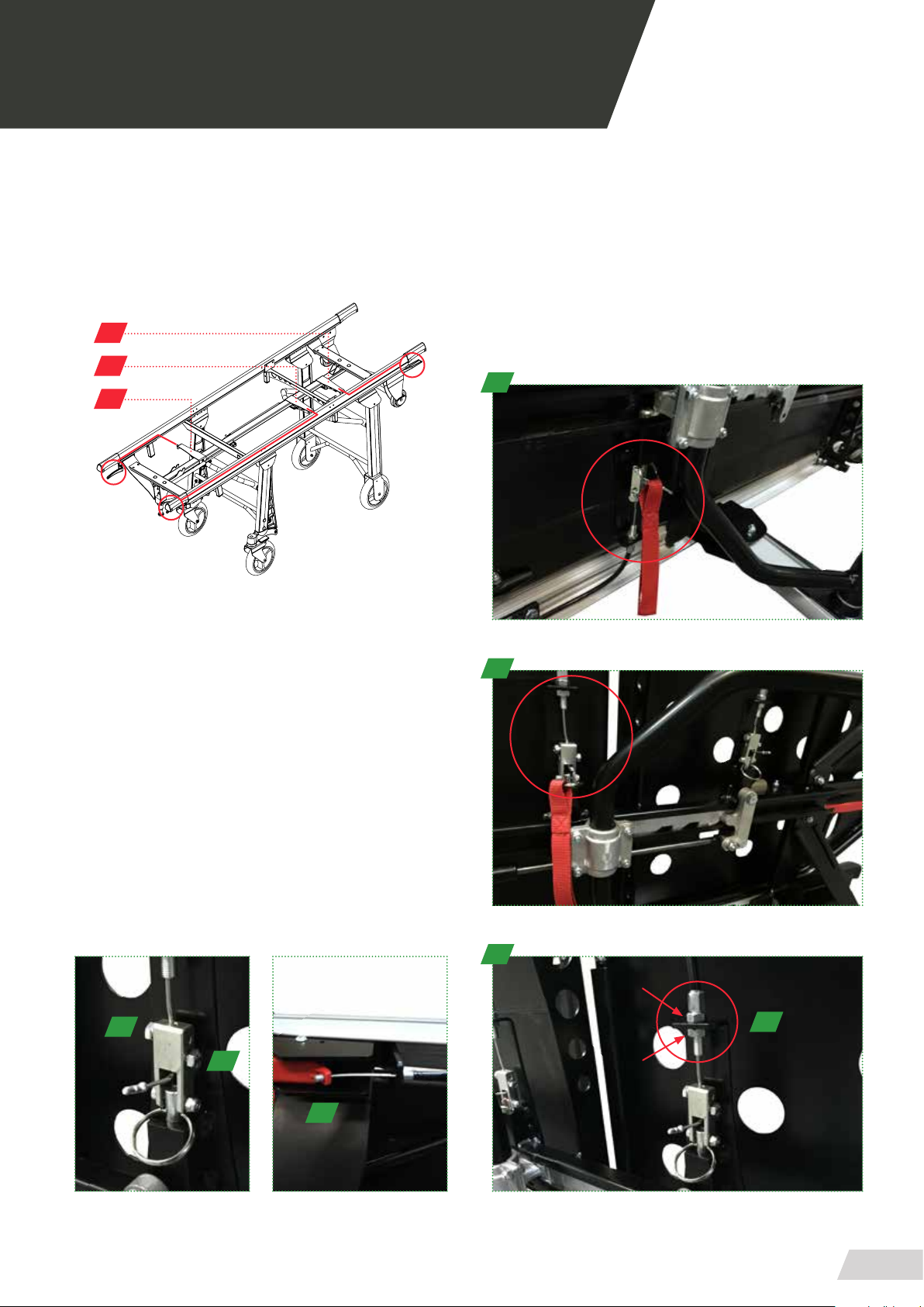
03.4 Tensors
To adjust the tension of the drive cables, the stretcher has
three sets of tensioners for adjunstment:
3
2
1
1
1. HANDLE UNLOCKING BACK LEGS
2. HANDLE UNLOCKING FRONT LEGS
3. INTERMEDIATE STOP SHAFT
To regulate the tensioners, you have a clamping ange
where you can replace the tensioning cable (if it breaks) or
regulate its tension.
To adjust the tension of the cable has two locknuts (D).
Using a wrench 11 loosen the nut 2 and adjust the tension
of the cable using the nut 1. Tighten the nuts 1 and 2 again.
If the cable breaks, proceed to cut the cap, loosen the screws
(A-B) and remove the cable pulling from the handle terminal
(C).
A
B
2
3
D
C
15
Page 16

Page 17
USER MANUAL // STRETCHER PC-615
Review 11/18
04 MOUNTING AND COMPONENTS
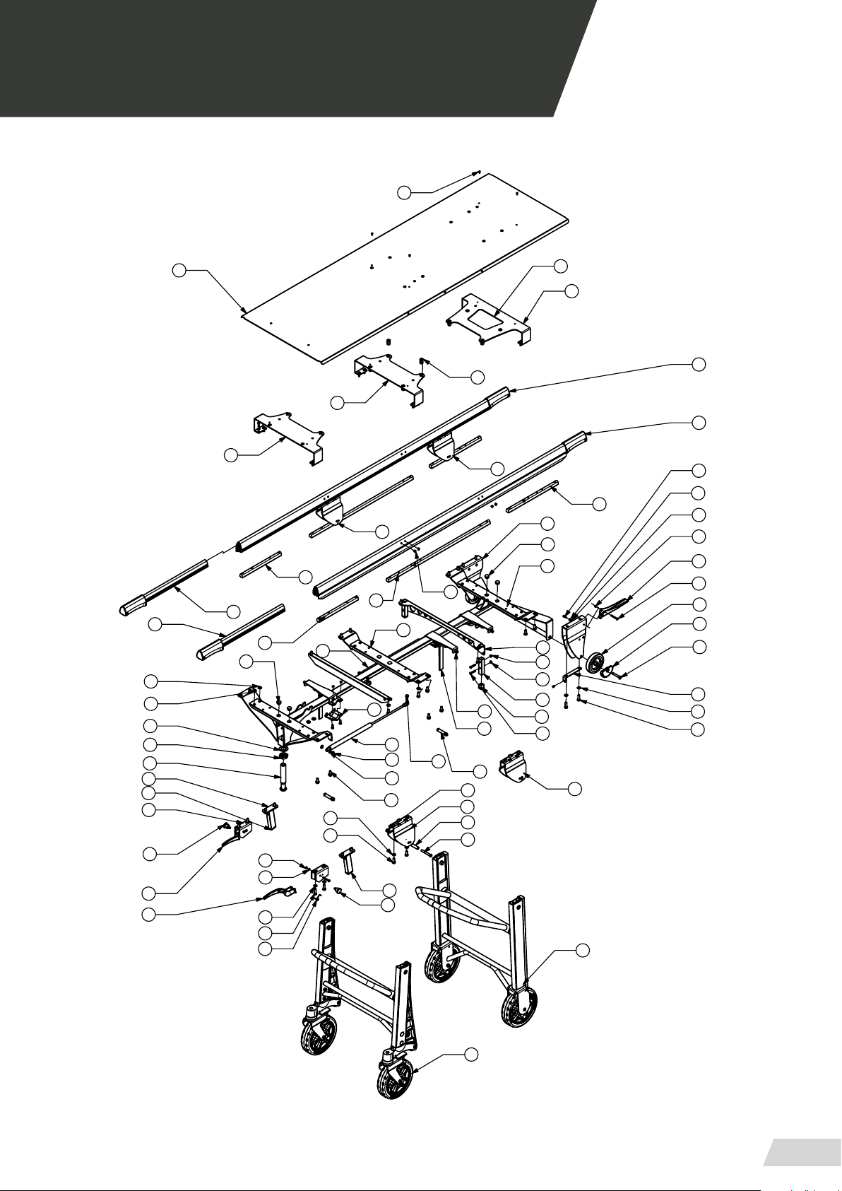
04.1 General view STRETCHER PC-615
43
30
54
29
29
18
19
2
51
51
42
59
16
4
55
14
40
24
23
2
19
56
44
62
63
64
32
12
63
48
18
6
20
10
66
63
48
4
40
58
53
15
5
5
8
66
34
8
41
28
28
2
2
45
15
26
56
6
5
66
66
31
57
61
34
38
9
62
46
3
61
22
27
60
17
63
47
37
17
Page 18

USER MANUAL // STRETCHER PC-615
Review 11/18
04 MOUNTING AND COMPONENTS
04.2 Bill of materials GENERAL VIEW STRETCHER PC-615
NUM. ELEMENT CODE - DESCRIPTION UNITS
1.01 PC6500-03182 - PERFIL SUPERIOR 2
1.02 PC6500-03460 - SUBCONJUNT MANETES EXTENSIBLES 4
1.03 PC6500-03970 - CONJUNT MANETA REFORÇADA
VERMELLA
1.04 PC6150-05002 - TOPE POTA POSTERIOR 2
1.05 PC6170-03520 - CONJUNT GUIA PC-617 1
1.06 PC6170-03092 - SUBCONJUNT TRAVESSER DAVANTER 2
1.07 PC6500-01282 - SUBCONJUNT TIRANT POTES LLARG 1
1.08 PC6170-01031 - CASQUELL POTES 4
1.09 PC6500-03470 - CASQUELL MANETES EXTENSIBLES 3
1.10 PC6500-03070 AMORTITZER 220MM-70N 1
1.11 VASTEG PISTÓ STABILUS 7873FA 1
1.12 PC6500-03080 - AMORTITZER 320MM-70N 1
1.13 VASTEG PISTÓ STABILUS 6008YF 1
1.14 PC6500-03242 - SOPORT MANETA ESQUERRA 2
1.15 PC6500-03950 - FEMELLA SUBJECCIO PATI DAVANTER 2
1.16 PC6100-03151 - TORRIO ENGANCHE 1
1.17 PC6500-03432 - SOPORT CABLE PATI 2
1.18 PC6170-03250 - FEMELLA SUBJECCIO CENTRAL 2
1.19 PC6500-03960 - FEMELLA SUBJECCIO MANETES
POSTERIORS
1.20 PC6500-03050 - BRIDA PATÍ 2
1.21 PC6500-03060 - COIXINET GIR PATI 2
1.22 CD-RUEDA-100 - RODA 100x24 2
1.23 2PC6170-03300 - MANETA DESPLAÇADA DRETA INJECCIÓ 1
1.24 PC6170-03330 - MANETA DESPLAÇADA ESQUERRA
INJECCIÓ
1.25 PC6170-03422 - PATI DAVANTER DRETA SIMPLE 1
1.26 PC6170-03432 - PATI DAVANTER ESQUERRA SIMPLE 1
1.27 PC6170-03460 - TOPE LATERAL CAMILLA 2
1.28 PC6150-03032 - SUPORT SAFATA DAVANTERA 1
1.29 PC6150-03012 - SUPORT SAFATA 2
1.30 PC6150-03020 - XAPA INCUBADORA 1
1.31 PC6170-03452 - TUB TOPE POTA DAVANTERA ALT 2
1.32 PC6500-03931 - MOLLA MANETA 2
1.33 PB4010-00060 - TERMINAL FUNDA CABLES T01-05 3
1.34 PC6150-03042 - LATERAL U SOPORT POTES INCUBADORA 4
1.35 PC6150-00010 - TAPA ADHESIVA NEGRE 13mm 4
18
1
2
1
Page 19

USER MANUAL // STRETCHER PC-615
Review 11/18
04 MOUNTING AND COMPONENTS
04.2 Bill of materials GENERAL VIEW STRETCHER PC-615
NUM. ELEMENT CODE - DESCRIPTION UNITS
1.36 PC6150-06000 - KIT DOBLE RODA ATAC CAMILLES PA-615 1
1.37 PC6150-04000 - CONJUNT POTA GIRATORIA ESTANDAR
INCUBADORA
1.38 PC6172-02000 - CONJUNT POTA FIXE ESTANDAR PC-617 1
1.39 PC6170-01062 - SUBCONJUNT TIRANT POTES EXTRA
LLARG
1.40 GN 822-7-C-ST - POM POSICIONADOR AMB BLOQUEIG 2
1.41 3111308601 - TORNILLO ISO7380 M8x60 CINCADO 4
1.42 31201241 - ARANDELA D-125 PARA M24 CINCADA 1
1.43 314030410 - REMACHE INOX Ø4x10 12
1.44 31305051 - TUERCA D-985 M-5 CINC 10
1.45 3110404161 - TORNILLO D-933 M4x16 CINCADO 3
1.46 31305041 - TUERCA D-985 M-4 CINCADA 4
1.47 3110408251 TORNILLO D-933 M8x25 CINCADO 6
1.48 3110408201 TORNILLO D-933 M8x20 CINCADO 22
1.49 3111208161 - TORNILLO D-7984 M-8x16 CINCADO 4
1.50 314020602 - TUERCA REMACHABLE M-6 S-VALONA HEXAGONAL
1.51 31209061 - ARANDELA D-7349 M-6 CINCADA 4
1.52 3110406161 - TORNILLO D-933 M6x16 CINCADO 8
1.53 3110408161 - TORNILLO D-933 M8x16 CINCADO 2
1.54 314021002 - TUERCA REMACHABLE M-10 S-VALONA
HEXAGONAL
1.55 TAPPLA-30x20 - TAPON PLASTICO INTERIOR 30x20 2
1.56 TAP-PLASTØ20 - TAPON PLASTICO FINAL Ø20 - Mod. 17-20 6
1.57 TAPPLA-20x20 - TAPON PLASTICO INTERIOR 20x20 2
1.58 TAP-PLASTØ10 - TAPON PLASTICO FINAL Ø10 - Mod. 17-10 8
1.59 31306241 - TUERCA D-439 M-24 CINCADA 1
1.60 3110808501 - TORNILLO D-7991 M8x50 2
1.61 3111306301 - TORNILLO ISO7380 M6x30 CINC 7
1.62 31201061 - ARANDELA D-125 M6 CINC 18
1.63 31201081 - ARANDELA D-125 M8 CINC 39
1.64 3111208251 - TORNILLO D-7984 M-8x25 CINCADO 2
1.65 3111306201 - TORNILLO ISO-7380 M6x20 CINCADO 12
1.66 31305061 - TUERCA D-985 M-6 CINC 12
1
1
8
8
19
Page 20
USER MANUAL // STRETCHER PC-615
Review 11/18
04 MOUNTING AND COMPONENTS
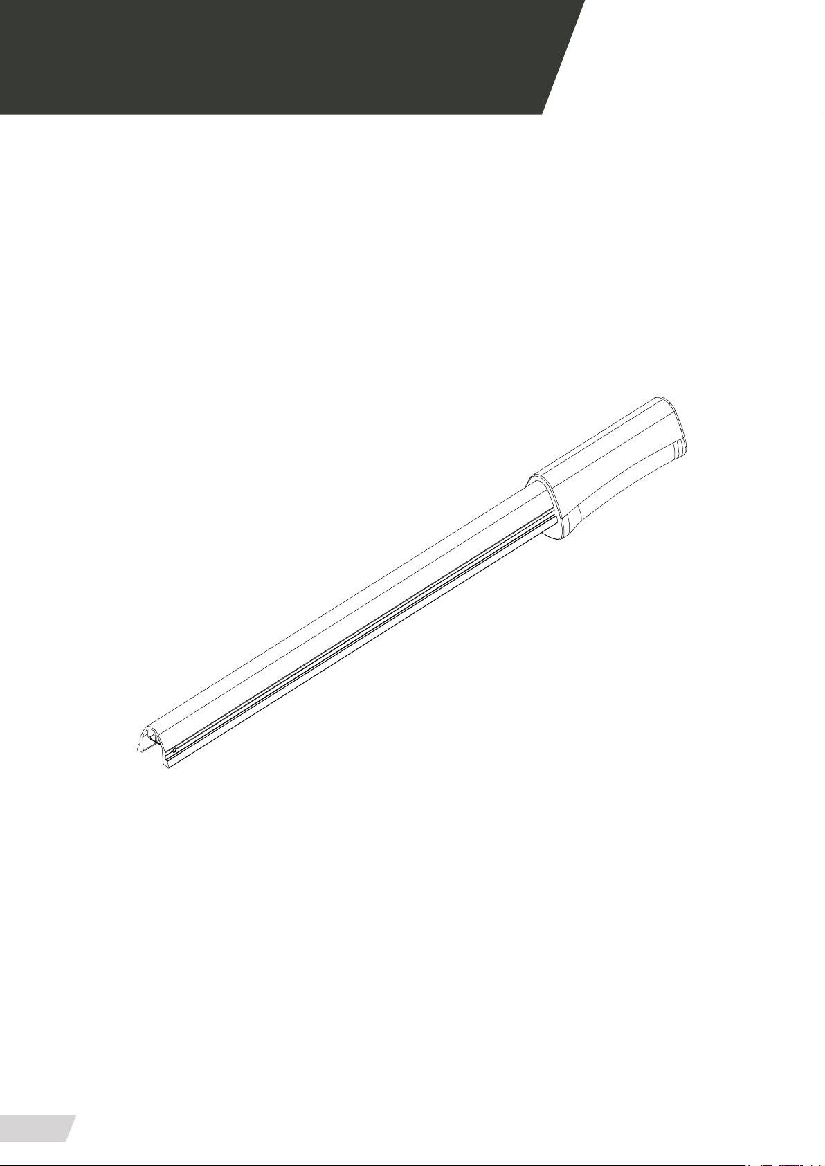
04.3 Telescopic hand grips PC-615
20
Page 21

USER MANUAL // STRETCHER PC-615
Review 11/18
04 MOUNTING AND COMPONENTS
04.3 Bill of materials TELESCOPIC HAND GRIPS PC-615
NUM. ELEMENT CODE - DESCRIPTION UNITS
2.01 PC6500-03310 - PERFIL MANETES EXTENSIBLES 1
2.02 PC6500-03320 - MANETA 1
2.03 PC6500-03340 - PALANCA BLOQUEJADORA 1
2.04 PC6500-03470 - CASQUELL MANETES EXTENSIBLES 2
2.05 PC6500-03351 - MOLLA MANETA EXTENSIBLE 1
2.06 PA1481-4X26N PASADOR ELASTICO D-1481 4X26 2
2.07 3111205201 CARGOL D-7984 M5X20 1
2.08 3110205201 TORNILLO D-912 M5X20 ZN 1
2.09 PC6500-03330 - PULSADOR 1
2.10 3160205201 ESPARRAGO D-913 M5X20 ZN 1
21
Page 22
USER MANUAL // STRETCHER PC-615
Review 11/18
04 MOUNTING AND COMPONENTS
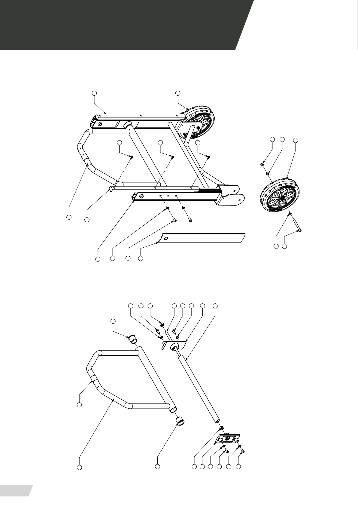
04.4 Standard xed leg set PC-615
9
19
2
9
1
16
4
14
5
13
10
19
19
10
5
15
7
3
14
16
8
11
2
3
14
8
6
16
6
14
16
12
16
14
22
Page 23

USER MANUAL // STRETCHER PC-615
Review 11/18
04 MOUNTING AND COMPONENTS
04.4 Bill of materials STANDARD FIXED LEG SET PC-615
NUM. ELEMENT CODE - DESCRIPTION UNITS
3.01 PC6170-02012 - SUBCONJUNT POTA FIXE 1
3.02 PC6170-01062 - SUBCONJUNT TIRANT POTES EXTRA
LLARG
3.03 PC6500-01261 - CONJUNT VARILLA TRAVESSER POTA 1
3.04 PC6500-02052 - TAPA EXTERIOR POTA DAVANTERA 2
3.05 PS2500-07000 - CONJUNT RODA PROMEBA PERFORMANCE 200x45mm
3.06 PC6500-01082 - SOPORT TIRANT 2
3.07 PC6500-01091 - TRAVESSER INCLINAT 1
3.08 PC6500-01350 - CASQUELL GIR TIRANTS 2
3.09 PC6170-02110 - BURLETE ALT 2
3.10 CASDIAM12X5 - CASQUILLO ØEXT12 ØINT8.1 A 5.5 4
3.11 PC6500-03060 - COIXINET GIR PATI 1
3.12 31305101 - TUERCA D-985 M-10 CINCADA 1
3.13 31305081 - TUERCA D-985 M-8 CINC 2
3.14 3111208161 - TORNILLO D-7984 M-8X16 CINCADO 4
3.15 3111308801 - TORNILLO ISO7380 M8X80 CINCADO 2
3.16 31203081 - ARANDELA D-6798A PARA M8 CINCADA 4
3.17 3111306121 - TORNILLO ISO7380 M6X12 CINC 2
3.18 31305051 - TUERCA D-985 M-5 CINC 2
3.19 3110905301 - TORNILLO D-7981 4.8x30 CINCADO 6
1
2
23
Page 24
USER MANUAL // STRETCHER PC-615
Review 11/18
04 MOUNTING AND COMPONENTS
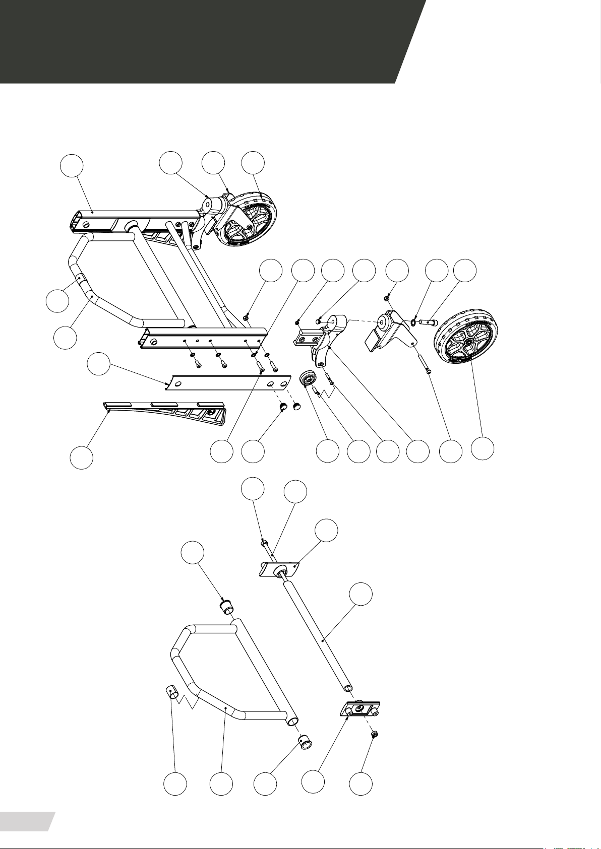
04.5 Standard revolving leg set PC-615
26
10
1
2
15
9
12
18
8
13
20
22
11
24
16
14
23
20
17
25
9
19
8
30
12
18
10
12
9
7
8
7
11
24
Page 25

USER MANUAL // STRETCHER PC-615
Review 11/18
04 MOUNTING AND COMPONENTS
04.5 Bill of materials STANDARD REVOLVING LEG SET PC-615
NUM. ELEMENT CODE - DESCRIPTION UNITS
4.01 PC6170-01012 - SUBCONJUNT ESTRUCTURA POTES
GIRATÒRIES
4.02 PC6500-01052 - TAPA EXTERIOR POTA POSTERIOR 2
4.03 PC6500-01082 - SOPORT TIRANT 2
4.04 PC6500-01091 - TRAVESSER INCLINAT 1
4.05 PC6500-01261 - CONJUNT VARILLA TRAVESSER POTA 1
4.06 31305101 - TUERCA D-985 M-10 CINCADA 1
4.07 PC6500-01350 - CASQUELL GIR TIRANTS 2
4.08 PS2500-07000 - CONJUNT RODA PROMEBA
PERFORMANCE 200x45mm
4.09 PC6500-01012 - SOPORT RODA POSTERIOR 2
4.10 PC6500-01282 - SUBCONJUNT TIRANT POTES LLARG 1
4.11 3069 - RUEDA DIAM.50MM REF. ARSA - 3069 2
4.12 PC6500-01200 - RODES GIRATÒRIES AMB FRE 2
4.13 TAP-PLASTØ22 - TAPON PLASTICO FINAL Ø22 - MOD. 17-22 4
4.14 TAP-PLASTØ14 - TAPON PLASTICO FINAL Ø14 - MOD. 17-14 2
4.15 PC6500-01220 - PATI RODA POSTERIOR ALT 2
4.16 PC6500-01161 - CASQUELL GIR POTES POSTERIORS 2
4.17 3110212501 - TORNILLO D-912 M-12x50 CINCADO 2
4.18 3111208301 - TORNILLO D-7984 M-8x30 CINCADO 4
4.19 3111308701 TORNILLO ISO7380 M8x70 CINCADO 2
4.20 31305081 - TUERCA D-985 M-8 CINC 6
4.21 3111208161 - TORNILLO D-7984 M-8x16 CINCADO 4
4.22 31203081 - ARANDELA D-6798A PARA M8 CINCADA 8
4.23 3111306401 - TORNILLO ISO7380 M6X40 CINC 2
4.24 31305061 - TUERCA D-985 M-6 CINC 2
4.25 31203123 - ARANDELA D-6798A PARA M12 PAVONADA 2
4.26 PC6500-03060 - COIXINET GIR PATI 1
1
2
25
Page 26
USER MANUAL // STRETCHER PC-615
Review 11/18
05 GENERAL MAINTENANCE
CLEANING
It is essential to keep the equipment clean to ensure a
proper use and durability of the set. A thorough clean
must be done periodically, especially in areas exposed
to dirt that may be damaged such as gears, connectors,
switches, etc.
Do not use high-pressure cleaning systems, they can
damage the product.
CONTROLS AND SELECTORS
Due to the intense and continuous use of mobile elements such as commands and switches, periodically
examine its proper operating.
There may be failures in micro-switches and wiring, inspect the attachments and the electrical or mechanical
connections that may exist.
GREASE
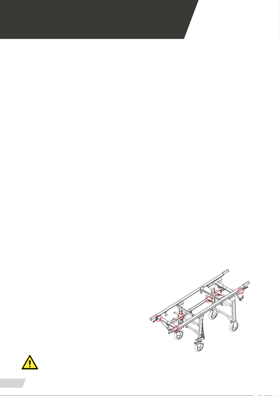
WEAR AREAS
Inspecting regularly on the system compo-nents for
signs of wear is a preventive measure that can reduce
breakdowns. Check possible lubricant leakages, grooves or bearing in poor condition.
MECHANICAL FIXING
We generally call mechanical xing elements to the
components used to x the product as a whole, mainly
screws and derivatives.
To some terms of use, due to vibrations or impacts certain elements may lose their tightening torque or xing
properties.
Periodically review that there are no loose elements,
especially on moving parts of the set. Please note and
always respect the recommended tightening torques.
REPLACEMENT OF COMPONENTS
Generally, every moving part should be greased. Our
products leave the factory completely greased and lubricated. However, it is possible that the elements are
degreased over time and the use of the product, either
by lubrication loss or dirt. Clean and grease periodically the aected areas according to the manufacturer’s
specications.
Check for loose, missing or worn parts. Perio-dically
examine every moving element to make sure that components are tighten.
This manual does not include procedures for all parts.
Qualied service personnel should replace cables, switches and certain mecha-nical parts without step-bystep procedures.
The qualied service personnel should contact our
commercial department for information about ordering spare parts and its installation.
MAKE SURE TO KEEP THESE AREAS FREE OF WATER AND HUMIDITY.
TAKE SPECIAL CARE NOT TO WET THEM WHILE WASHING THE SET.
26
Page 27

USER MANUAL // STRETCHER PC-615
Review 11/18
06 LEGAL NOTICES
This document may contain technical inaccuracies or
typographical errors.
Changes are periodically added to the information
herein; these changes will be incorporated in new editions of the publication.
Promeba, S.L. reserves the right to make, if considered
appropiate, any modication or improvement to the
products described in this publication.
Promeba, S.L. may have patents or patent applications
which address themes described in this document. The
possession of this document does not entitle no license to these patents.
The information contained in this document does not
aect or change the specications or product warranties of Promeba, S.L.
No part of this document shall operate as express or
implied license or compensation under the intellectual
property rights of Promeba, S.L. or third party.
All the information contained in this document has
been obtained in specic environments and it is presented as an illustration. The results obtained in other
operating environments may vary.
Promeba, S.L. may use or distribute the information
that the client provides in whatever way they see t,
without incurring any obligation with the client.
27
Page 28

USER MANUAL // STRETCHER PC-615
Review 11/18
07 PRODUCT WARRANTY
Promeba, S.L. warrants that their products have suc-
cessfully passed all quality controls, both functional
and material. The warranty period is 2 years from the
date of purchase.
This warranty will only be granted when the original
invoice or sales receipt (indicating the date of purchase, model and the distributor’s name) is presented together with the defective product during the warranty
period. Promeba, S.L. reserves the right to not oer
the free warranty service if the indicated documents
are not presented or if the information provided by the
consumer is false, incomplete or illegible.
1. This warranty shall not apply if the model’s name or the
serial number has been altered, removed, disappeared or
is illegible.
2. This warranty does not cover transportation costs or
risks associated with the transport of the product to and
from Promeba, S.L.
3. This warranty does not cover any of the following cases:
A. Regular maintenance and reparation or replacement
of parts from the normal wear and use.
B. Consumables (components that may need periodic replacements during the product’s life, such as non-rechargeable batteries, bulbs, etc.)
C. Damages or defects resulting from the use, operation
or improper treatment of the product and not caused by
a normal use of it.
D. Damages arising from:
ii. Use of components not supplied with the product
or incorrect installation of accessory parts previously
untested.
iii. States or defects of the system in which the product
is incorporated with the exception of other products of
Promeba, S.L. designed for its use with the product.
iv. Product use with accessories, peripheral units and
other products of a type, condition or standard not established by Promeba, S.L.
v. The manufacturer or distributor shall be solely responsible for determining the sending of parts for its reparation or the replacement of the product in its entirety. In no circumstance shall operators be send to such
reparation or product replacement.
Except in the cases mentioned above, Promeba, S.L.
shall not give any guarantees in relation to the product, operation, accuracy, reliability or adaptability for
an equipment logical purpose or any other type. If this
exception is not lawful or established in the law, Pro-
meba, S.L. shall limit or exclude their guarantees only
to the extent that the applicable law permits it.
The only obligation of Promeba, S.L. regarding this
warranty is to repair or replace the parts subjected to
the terms and condition of this warranty.
Promeba, S.L. is not liable for loss or damages to products, this warranty or others, including economic loss
or not assessable damage; the price paid for the product; loss of prots, incomes, information, usufruct or
use of the product or associated products or indirect
loss or damage, accidental or critical.
i. Improper use, including:
- Treatment resulting in damages or physical changes,
surface or appearance changes of the product.
- Installation, use or storage of the product in a manner
inconsistent with the instructions described by Promeba,
S.L.
- Product maintenance in a manner inconsistent with the
instructions of Promeba, S.L. for a proper maintenance.
- Installation or product use in a manner inconsistent with
the technical or security standards of the country where it
is used or installed.
28
This clause refers to whether the loss or damage is due
to a product deterioration or inoperability associated
to defects or unavailability of Promeba, S.L. that caused a downtime, user’s time loss or a business interruption.
In the cases in which the law prohibits or limits these
responsibility exclusions, Promeba, S.L. shall exclude
or limit their responsibility only to the extent that the
law allows. For example, many countries forbid the exclusion or limitation of damages caused by negligence,
gross negligence, wilful misconduct, fraud and similar
acts. The responsibility of Promeba, S.L. in this warran-
ty shall not exceed, in any case, the price paid for the
product, but if the applicable law permits only responsibility limitations of major responsibilities, these shall
be applied.
Page 29

Page 30

All rights reserved. Variations can be done whitout notice.
Promeba, S.L. is to be considered not responsible for damages caused by the lack or the wrongness
of the information here mentioned.
PROMEBA, S.L.
ER-0687/1998
Ctra C-16 Km 59.5 · 08650 Sallent (Barcelona) · SPAIN
T. 93 837 12 00 · Fax 93 820 61 08
[email protected] · www.promeba.com
 Loading...